EP4037217A2 - Kommunikationssystem - Google Patents
Kommunikationssystem Download PDFInfo
- Publication number
- EP4037217A2 EP4037217A2 EP22153782.2A EP22153782A EP4037217A2 EP 4037217 A2 EP4037217 A2 EP 4037217A2 EP 22153782 A EP22153782 A EP 22153782A EP 4037217 A2 EP4037217 A2 EP 4037217A2
- Authority
- EP
- European Patent Office
- Prior art keywords
- communication device
- data
- base station
- subframes
- narrowband
- Prior art date
- Legal status (The legal status is an assumption and is not a legal conclusion. Google has not performed a legal analysis and makes no representation as to the accuracy of the status listed.)
- Pending
Links
- 238000004891 communication Methods 0.000 title claims abstract description 450
- 238000000034 method Methods 0.000 claims description 60
- 101000741965 Homo sapiens Inactive tyrosine-protein kinase PRAG1 Proteins 0.000 abstract description 4
- 102100038659 Inactive tyrosine-protein kinase PRAG1 Human genes 0.000 abstract description 4
- 230000005540 biological transmission Effects 0.000 description 71
- 238000013468 resource allocation Methods 0.000 description 22
- 230000011664 signaling Effects 0.000 description 17
- 238000013459 approach Methods 0.000 description 8
- 238000012545 processing Methods 0.000 description 7
- 230000015654 memory Effects 0.000 description 6
- 230000008901 benefit Effects 0.000 description 5
- 230000002776 aggregation Effects 0.000 description 4
- 238000004220 aggregation Methods 0.000 description 4
- 230000001413 cellular effect Effects 0.000 description 4
- 238000010586 diagram Methods 0.000 description 4
- 230000006870 function Effects 0.000 description 4
- 102100036409 Activated CDC42 kinase 1 Human genes 0.000 description 3
- 230000007774 longterm Effects 0.000 description 3
- 238000007726 management method Methods 0.000 description 3
- 238000012986 modification Methods 0.000 description 3
- 230000004048 modification Effects 0.000 description 3
- 230000009467 reduction Effects 0.000 description 3
- 101100465000 Mus musculus Prag1 gene Proteins 0.000 description 2
- 230000008859 change Effects 0.000 description 2
- 230000036541 health Effects 0.000 description 2
- 238000012423 maintenance Methods 0.000 description 2
- 238000010295 mobile communication Methods 0.000 description 2
- 238000012544 monitoring process Methods 0.000 description 2
- 241001465754 Metazoa Species 0.000 description 1
- 230000004931 aggregating effect Effects 0.000 description 1
- 238000004590 computer program Methods 0.000 description 1
- 230000001419 dependent effect Effects 0.000 description 1
- 238000011161 development Methods 0.000 description 1
- 230000018109 developmental process Effects 0.000 description 1
- 238000005516 engineering process Methods 0.000 description 1
- 238000009408 flooring Methods 0.000 description 1
- 238000010438 heat treatment Methods 0.000 description 1
- 230000006872 improvement Effects 0.000 description 1
- 230000003993 interaction Effects 0.000 description 1
- 238000012806 monitoring device Methods 0.000 description 1
- 230000004044 response Effects 0.000 description 1
- XLYOFNOQVPJJNP-UHFFFAOYSA-N water Substances O XLYOFNOQVPJJNP-UHFFFAOYSA-N 0.000 description 1
Images



Classifications
-
- H—ELECTRICITY
- H04—ELECTRIC COMMUNICATION TECHNIQUE
- H04W—WIRELESS COMMUNICATION NETWORKS
- H04W4/00—Services specially adapted for wireless communication networks; Facilities therefor
- H04W4/70—Services for machine-to-machine communication [M2M] or machine type communication [MTC]
-
- H—ELECTRICITY
- H04—ELECTRIC COMMUNICATION TECHNIQUE
- H04W—WIRELESS COMMUNICATION NETWORKS
- H04W28/00—Network traffic management; Network resource management
- H04W28/02—Traffic management, e.g. flow control or congestion control
- H04W28/04—Error control
-
- H—ELECTRICITY
- H04—ELECTRIC COMMUNICATION TECHNIQUE
- H04L—TRANSMISSION OF DIGITAL INFORMATION, e.g. TELEGRAPHIC COMMUNICATION
- H04L1/00—Arrangements for detecting or preventing errors in the information received
- H04L1/12—Arrangements for detecting or preventing errors in the information received by using return channel
- H04L1/16—Arrangements for detecting or preventing errors in the information received by using return channel in which the return channel carries supervisory signals, e.g. repetition request signals
- H04L1/1607—Details of the supervisory signal
-
- H—ELECTRICITY
- H04—ELECTRIC COMMUNICATION TECHNIQUE
- H04L—TRANSMISSION OF DIGITAL INFORMATION, e.g. TELEGRAPHIC COMMUNICATION
- H04L1/00—Arrangements for detecting or preventing errors in the information received
- H04L1/12—Arrangements for detecting or preventing errors in the information received by using return channel
- H04L1/16—Arrangements for detecting or preventing errors in the information received by using return channel in which the return channel carries supervisory signals, e.g. repetition request signals
- H04L1/1607—Details of the supervisory signal
- H04L1/1614—Details of the supervisory signal using bitmaps
-
- H—ELECTRICITY
- H04—ELECTRIC COMMUNICATION TECHNIQUE
- H04L—TRANSMISSION OF DIGITAL INFORMATION, e.g. TELEGRAPHIC COMMUNICATION
- H04L1/00—Arrangements for detecting or preventing errors in the information received
- H04L1/12—Arrangements for detecting or preventing errors in the information received by using return channel
- H04L1/16—Arrangements for detecting or preventing errors in the information received by using return channel in which the return channel carries supervisory signals, e.g. repetition request signals
- H04L1/1607—Details of the supervisory signal
- H04L1/1621—Group acknowledgement, i.e. the acknowledgement message defining a range of identifiers, e.g. of sequence numbers
-
- H—ELECTRICITY
- H04—ELECTRIC COMMUNICATION TECHNIQUE
- H04L—TRANSMISSION OF DIGITAL INFORMATION, e.g. TELEGRAPHIC COMMUNICATION
- H04L1/00—Arrangements for detecting or preventing errors in the information received
- H04L1/12—Arrangements for detecting or preventing errors in the information received by using return channel
- H04L1/16—Arrangements for detecting or preventing errors in the information received by using return channel in which the return channel carries supervisory signals, e.g. repetition request signals
- H04L1/1607—Details of the supervisory signal
- H04L1/1628—List acknowledgements, i.e. the acknowledgement message consisting of a list of identifiers, e.g. of sequence numbers
-
- H—ELECTRICITY
- H04—ELECTRIC COMMUNICATION TECHNIQUE
- H04L—TRANSMISSION OF DIGITAL INFORMATION, e.g. TELEGRAPHIC COMMUNICATION
- H04L1/00—Arrangements for detecting or preventing errors in the information received
- H04L1/12—Arrangements for detecting or preventing errors in the information received by using return channel
- H04L1/16—Arrangements for detecting or preventing errors in the information received by using return channel in which the return channel carries supervisory signals, e.g. repetition request signals
- H04L1/1607—Details of the supervisory signal
- H04L1/1635—Cumulative acknowledgement, i.e. the acknowledgement message applying to all previous messages
-
- H—ELECTRICITY
- H04—ELECTRIC COMMUNICATION TECHNIQUE
- H04L—TRANSMISSION OF DIGITAL INFORMATION, e.g. TELEGRAPHIC COMMUNICATION
- H04L1/00—Arrangements for detecting or preventing errors in the information received
- H04L1/12—Arrangements for detecting or preventing errors in the information received by using return channel
- H04L1/16—Arrangements for detecting or preventing errors in the information received by using return channel in which the return channel carries supervisory signals, e.g. repetition request signals
- H04L1/18—Automatic repetition systems, e.g. Van Duuren systems
-
- H—ELECTRICITY
- H04—ELECTRIC COMMUNICATION TECHNIQUE
- H04L—TRANSMISSION OF DIGITAL INFORMATION, e.g. TELEGRAPHIC COMMUNICATION
- H04L1/00—Arrangements for detecting or preventing errors in the information received
- H04L1/12—Arrangements for detecting or preventing errors in the information received by using return channel
- H04L1/16—Arrangements for detecting or preventing errors in the information received by using return channel in which the return channel carries supervisory signals, e.g. repetition request signals
- H04L1/18—Automatic repetition systems, e.g. Van Duuren systems
- H04L1/1812—Hybrid protocols; Hybrid automatic repeat request [HARQ]
-
- H—ELECTRICITY
- H04—ELECTRIC COMMUNICATION TECHNIQUE
- H04L—TRANSMISSION OF DIGITAL INFORMATION, e.g. TELEGRAPHIC COMMUNICATION
- H04L1/00—Arrangements for detecting or preventing errors in the information received
- H04L1/12—Arrangements for detecting or preventing errors in the information received by using return channel
- H04L1/16—Arrangements for detecting or preventing errors in the information received by using return channel in which the return channel carries supervisory signals, e.g. repetition request signals
- H04L1/18—Automatic repetition systems, e.g. Van Duuren systems
- H04L1/1812—Hybrid protocols; Hybrid automatic repeat request [HARQ]
- H04L1/1819—Hybrid protocols; Hybrid automatic repeat request [HARQ] with retransmission of additional or different redundancy
-
- H—ELECTRICITY
- H04—ELECTRIC COMMUNICATION TECHNIQUE
- H04L—TRANSMISSION OF DIGITAL INFORMATION, e.g. TELEGRAPHIC COMMUNICATION
- H04L5/00—Arrangements affording multiple use of the transmission path
- H04L5/003—Arrangements for allocating sub-channels of the transmission path
- H04L5/0053—Allocation of signalling, i.e. of overhead other than pilot signals
- H04L5/0055—Physical resource allocation for ACK/NACK
-
- H—ELECTRICITY
- H04—ELECTRIC COMMUNICATION TECHNIQUE
- H04L—TRANSMISSION OF DIGITAL INFORMATION, e.g. TELEGRAPHIC COMMUNICATION
- H04L5/00—Arrangements affording multiple use of the transmission path
- H04L5/0091—Signalling for the administration of the divided path, e.g. signalling of configuration information
- H04L5/0092—Indication of how the channel is divided
-
- H—ELECTRICITY
- H04—ELECTRIC COMMUNICATION TECHNIQUE
- H04L—TRANSMISSION OF DIGITAL INFORMATION, e.g. TELEGRAPHIC COMMUNICATION
- H04L5/00—Arrangements affording multiple use of the transmission path
- H04L5/0091—Signalling for the administration of the divided path, e.g. signalling of configuration information
- H04L5/0094—Indication of how sub-channels of the path are allocated
-
- H—ELECTRICITY
- H04—ELECTRIC COMMUNICATION TECHNIQUE
- H04W—WIRELESS COMMUNICATION NETWORKS
- H04W72/00—Local resource management
- H04W72/04—Wireless resource allocation
- H04W72/044—Wireless resource allocation based on the type of the allocated resource
- H04W72/0446—Resources in time domain, e.g. slots or frames
-
- H—ELECTRICITY
- H04—ELECTRIC COMMUNICATION TECHNIQUE
- H04W—WIRELESS COMMUNICATION NETWORKS
- H04W72/00—Local resource management
- H04W72/04—Wireless resource allocation
- H04W72/044—Wireless resource allocation based on the type of the allocated resource
- H04W72/0453—Resources in frequency domain, e.g. a carrier in FDMA
-
- H—ELECTRICITY
- H04—ELECTRIC COMMUNICATION TECHNIQUE
- H04W—WIRELESS COMMUNICATION NETWORKS
- H04W72/00—Local resource management
- H04W72/20—Control channels or signalling for resource management
- H04W72/23—Control channels or signalling for resource management in the downlink direction of a wireless link, i.e. towards a terminal
Definitions
- the present invention relates to mobile communications devices and networks, particularly but not exclusively those operating according to the 3rd Generation Partnership Project (3GPP) standards or equivalents or derivatives thereof.
- 3GPP 3rd Generation Partnership Project
- the invention has particular although not exclusive relevance to high data rate transmissions for machine-type communication devices.
- (user) communication devices also known as user equipment (UE), for example mobile telephones
- UE user equipment
- base stations In their communication with each other, communication devices and base stations use licensed radio frequencies, which are typically divided into frequency bands and/or time blocks.
- LTE Long Term Evolution
- EPC Evolved Packet Core
- E-UTRAN Evolved UMTS Terrestrial Radio Access Network
- a NodeB or an eNB in LTE
- Communication devices might be, for example, mobile communication devices such as mobile telephones, smartphones, user equipment, personal digital assistants, laptop/tablet computers, web browsers, e-book readers and/or the like. Such mobile (or even generally stationary) devices are typically operated by a user.
- IoT Internet of Things'
- NB-IoT Narrow-Band IoT
- IoT devices can be implemented as a part of a (generally) stationary apparatus such as vending machines, roadside sensors, POS terminals, although some IoT devices can be embedded in non-stationary apparatus (e.g. vehicles) or attached to animals or persons to be monitored/tracked.
- the Internet of Things is a network of devices (or “things") equipped with appropriate electronics, software, sensors, network connectivity, and/or the like, which enables these devices to collect and exchange data with each other and with other communication devices.
- IoT devices are sometimes also referred to as Machine-Type Communication (MTC) communication devices or Machine-to-Machine (M2M) communication devices.
- MTC Machine-Type Communication
- M2M Machine-to-Machine
- the present application refers to MTC devices in the description but it will be appreciated that the technology described can be implemented on any communication devices (mobile and/or generally stationary) that can connect to a communications network for sending/receiving data, regardless of whether such communication devices are controlled by human input or software instructions stored in memory.
- MTC devices connect to the network to send data to or to receive data from a remote 'machine' (e.g. a server) or user.
- MTC devices use communication protocols and standards that are optimised for mobile telephones or similar user equipment.
- MTC devices once deployed, typically operate without requiring human supervision or interaction, and follow software instructions stored in an internal memory. MTC devices might also remain stationary and/or inactive for a long period of time.
- the specific network requirements to support MTC (IoT) devices have been dealt with in 3GPP technical report (TR) 36.888 V12.0.0 and 3GPP TR 23.720 V13.0.0. Further network requirements relating to MTC devices are disclosed in the 3GPP technical specification (TS) 22.368 V13.1.0. The contents of these 3GPP documents are incorporated herein by reference.
- IoT and other machine-type communication devices via cellular networks is proving to be a significant opportunity for mobile operators.
- eMTC enhanced MTC
- NB-IoT narrowband IoT
- MTC devices which may be referred to as 'reduced bandwidth MTC devices'
- eMTC devices will support only a limited bandwidth (typically 1.4 MHz or 180kHz in downlink and uplink) compared to the total LTE bandwidth. This allows such reduced bandwidth MTC devices to be made more economically (having fewer/simplified components) compared to MTC devices and other communication devices supporting a larger bandwidth and/or having more complicated components.
- LTE system bandwidths are typically larger than 1.4MHz (i.e. up to 20MHz)
- the system bandwidth is divided into a plurality of 'narrowbands' (or 'sub-bands'), each narrowband comprising a maximum of six physical resource blocks (PRBs), which is the maximum number of PRBs that a 1.4MHz bandwidth limited MTC device can use in LTE.
- PRBs physical resource blocks
- MTC devices In order to mitigate the risk of MTC devices not receiving some transmissions (for example, due to lack of network coverage (e.g. when deployed indoors), in combination with the often limited functionality of MTC devices), it has also been proposed to increase the coverage of certain LTE transmissions (channels) for MTC devices.
- One approach for the enhancement of coverage for MTC devices is the repetition of the same information across multiple (e.g. two, three, four, or more) sub-frames.
- the base station duplicates the transmitted information in the time domain (the base station re-transmits the same information in one or more sub-frames subsequent to the sub-frame in which that information is first sent).
- a coverage enhanced MTC device can be configured to combine the multiple copies of the (same) information received in the multiple sub-frames, and after combining the received information, the coverage enhanced MTC device is more likely to be able to decode transmitted data successfully than based on a single copy of the information.
- 3GPP specified two coverage enhancement (CE) modes for MTC devices CE Mode A, which employs a relatively small number of repetitions (or no repetition at all); and CE Mode B, which employs a large number of repetitions (and may also employ a higher transmission power).
- the Rel-13 standards including the introduction of narrowbands, primarily address complexity reduction, extended battery life, and coverage enhancements for MTC devices such as sensors, meters, smart readers, and similar.
- the introduction of the NB-IoT type UE category addresses low data rate use cases, (e.g. requiring less than 200kbps), whilst the introduction of the eMTC type UE category can address data rates in the order of 300kbps when Half Duplex Frequency Division Duplex (HD-FDD) transmission is employed or 800kpbs when Full Duplex Frequency Division Duplex (FD-FDD) transmission is employed.
- HD-FDD Half Duplex Frequency Division Duplex
- FD-FDD Full Duplex Frequency Division Duplex
- MTC devices/use cases that are of primary focus
- the Rel-13 standards also meet the requirements of other types of MTC devices/use cases, such as those of voice capable wearable devices and health monitoring devices.
- MTC devices/use cases that are not fully covered and/or supported by the Rel-13 improvements.
- MTC devices/use cases requiring higher data rates (e.g. above 1 Mbps), mobility, and MTC devices that support/use delay sensitive services.
- the present invention seeks to provide systems, devices and methods for at least partially addressing one or more of these issues.
- the invention provides a base station for a communication system, wherein the base station comprises: a controller operable to generate control information for assigning communication resources for transmitting data to a machine type communication device; and a transceiver operable to: transmit the generated control information to the machine type communication device; transmit data to the machine type communication device using the assigned communication resources; and receive, from the machine type communication device, ACK/NACK feedback for data transmitted to the machine type communication device; wherein the data is transmitted in a number of data bundles in sequence (e.g.
- each data bundle being transmitted in a sequence of downlink sub-frames; wherein the ACK/NACK feedback comprises respective ACK/NACK feedback for each bundle; wherein the controller is operable to determine a starting sub-frame in which respective ACK/NACK feedback for a first PDSCH bundle is expected based on the last sub-frame in which a last data bundle is transmitted, the number of data bundles, and whether or not transmission of the data bundles is repeated.
- the invention provides a machine type communication device for a communication system, wherein the machine type communication device comprises: a transceiver operable to receive: control information for assigning communication resources for transmitting data to the machine type communication device; and data using the assigned communication resources, wherein the data is transmitted in a number of data bundles in sequence (e.g.
- a controller operable to generate ACK/NACK feedback for data received by the machine type communication device, wherein the ACK/NACK feedback comprises respective ACK/NACK feedback for each bundle; wherein the controller is operable to determine a starting sub-frame in which respective ACK/NACK feedback for a first PDSCH bundle is expected based on the last sub-frame in which a last data bundle is transmitted, the number of data bundles, and whether or not transmission of the data bundles is repeated; and wherein the transceiver is operable to transmit, to the base station, the generated feedback based on the determined starting sub-frame.
- the invention provides a base station for a communication system, wherein the base station comprises: a controller operable to generate control information for assigning communication resources for transmitting data to a machine type communication device; and a transceiver operable to transmit the generated control information to the machine type communication device, to transmit data to the machine type communication device using the assigned communication resources, and to receive, from the machine type communication device ACK/NACK feedback for data transmitted to the machine type communication device; wherein the ACK/NACK feedback comprises one ACK/NACK indication for acknowledging data transmitted in a plurality of subframes.
- the invention provides a base station for a communication system, wherein the base station comprises: a controller operable to generate control information for assigning communication resources for transmitting data to a machine type communication device, wherein the control information comprises one downlink control indication for assigning at least one of: (i) communication resources in each of a plurality of subframes; and (ii) communication resources in each of a plurality of narrowbands in the same subframe; and a transceiver operable to transmit the generated control information to the machine type communication device, to transmit data to the machine type communication device using the assigned communication resources.
- the invention provides a machine type communication device for a communication system, the machine type communication device comprising: a transceiver operable to receive: control information for assigning communication resources for transmitting data to a machine type communication device; and data using the assigned communication resources; and a controller operable to generate ACK/NACK feedback for data received by the machine type communication device, wherein the ACK/NACK feedback comprises one ACK/NACK indication for acknowledging data transmitted in a plurality of subframes; and wherein the transceiver is operable to transmit, to the base station, the generated feedback.
- the invention provides a machine type communication device for a communication system, wherein the machine type communication device comprises: a transceiver operable to receive, from a base station: control information for assigning communication resources for transmitting data to the machine type communication device, wherein the control information comprises one downlink control indication for assigning at least one of: (i) communication resources in each of a plurality of subframes; and (ii) communication resources in each of a plurality of narrowbands in the same subframe; and data using the assigned communication resources.
- aspects of the invention extend to corresponding systems, methods, and computer program products such as computer readable storage media having instructions stored thereon which are operable to program a programmable processor to carry out a method as described in the aspects and possibilities set out above or recited in the claims and/or to program a suitably adapted computer to provide the apparatus recited in any of the claims.
- 'legacy' refers to methods and/or apparatus known to those familiar with the relevant standards at the priority date of this application and in particular, but not exclusively, to methods and/or apparatus as standardised at the priority date (for example, but not limited to, as standardised in Release 13 or earlier of the relevant 3GPP standards).
- FIG 1 schematically illustrates a mobile (cellular) telecommunication system 1 in which communication devices 3 (such as mobile telephone 3-1 and MTC device 3-2) can communicate with each other and/or with other communication nodes via an E-UTRAN base station 5 (denoted 'eNB') and a core network 7.
- communication devices 3 such as mobile telephone 3-1 and MTC device 3-2
- E-UTRAN base station 5 denoted 'eNB'
- core network 7 a core network 7.
- the system when implemented, will typically include other base stations and communication devices.
- the base station 5 is connected to the core network 7 via an S1 interface.
- the core network 7 includes, amongst others: a gateway for connecting to other networks, such as the Internet and/or to servers hosted outside the core network 7; a mobility management entity (MME) for keeping track of the locations of the communication devices 3 (e.g. the mobile telephone and the MTC device) within the communication network 1; and a home subscriber server (HSS) for storing subscription related information (e.g. information identifying which communication device 3 is configured as a machine-type communication device) and for storing control parameters specific for each communication device 3.
- MME mobility management entity
- HSS home subscriber server
- the base station 5 is configured to provide a number of control channels, including, for example, a physical downlink control channel (PDCCH) and a physical uplink control channel (PUCCH), and a number of data channels, including, for example, a Physical Downlink Shared Channel (PDSCH) and a Physical Uplink Shared Channel (PUSCH).
- the PDCCH (or an MTC specific PDCCH, 'MPDCCH') is used by the base station 5 for allocating resources to the communication devices 3 (typically by sending respective UE-specific downlink control information (DCI) to each communication device 3 that has been scheduled in the current scheduling round).
- the PUCCH is used by the communication devices 3 for sending UE-specific uplink control information (UCI) to the base station 5 (e.g.
- the PDSCH is the main data bearing channel which carries downlink user data, such as downlink data for a particular communication device 3 scheduled via associated DCI signalling.
- the PDSCH also carries system information relevant to the cell of the base station 5.
- the PUSCH carries uplink user data from the communication devices 3 using resources allocated by the base station 5 (based on appropriate scheduling request UCI(s) received via the PUCCH).
- the system bandwidth of the base station 5 of Figure 1 is divided into a plurality of non-overlapping narrowbands (e.g. a maximum of six PRBs per narrowband).
- the narrowbands within the system bandwidth are allocated such that it is possible to maintain efficient resource allocation signalling for the narrowbands for Rel-13 low complexity MTC UEs.
- Each communication device 3 may fall into one or more of categories of UEs.
- a first category of UEs include conventional (i.e. non-MTC) communication devices, such as mobile telephones, that are capable of communicating over the entire bandwidth available in the cell of the base station 5.
- a second category of UEs include NB-IoT devices (and/or the like) capable of using a 180kHz bandwidth only (1 PRB).
- a third category of UEs include Rel-13 MTC/eMTC devices capable of using up to a 1.4 MHz bandwidth.
- a fourth category of UEs include 'further enhanced' MTC ('FeMTC') devices which might have more sophisticated circuitry than conventional MTC/eMTC devices and which are capable of using more than a 1.4 MHz bandwidth.
- the second to fourth categories of UEs include various reduced bandwidth UEs (such as MTC devices and optionally mobile telephones when configured with MTC functionality), which may not be able or configured to communicate over the entire bandwidth available in the cell of the base station 5 (although devices in each category may support a different respective bandwidth).
- various reduced bandwidth UEs such as MTC devices and optionally mobile telephones when configured with MTC functionality
- the mobile telephone 3-1 falls into the first category of UEs, and it may also fall into one or more of the other categories (e.g. when running an MTC application). Therefore, the mobile telephone 3-1 is able to use the entire system bandwidth.
- the MTC device 3-2 falls into the fourth category of UEs, and it is able to use more than a 1.4 MHz bandwidth (although not the entire system bandwidth). It will be appreciated that the MTC device 3-2 may fall into the second or third UE category when it is operating as an NB-IoT device or an eMTC device, respectively.
- this system is configured to support higher/flexible data rates for compatible communication devices (e.g. at least the first and fourth category of UEs) than the data rates that can be achieved using the current (e)MTC standards (using a 1.4 MHz bandwidth / six PRBs).
- such support for higher data rates may be realised by the base station 5 scheduling its downlink transmissions, for compatible communication devices 3, into multiple (consecutive) downlink subframes during which the scheduled communication devices 3 are not scheduled/required to transmit data (including acknowledgements) in the uplink.
- Using such a sequence (or sequences) of subframes beneficially allows the communication devices 3 to receive data substantially continuously (and, if appropriate, at a potentially higher data rate than what is currently possible for eMTC devices).
- the communication devices 3 that are scheduled this way can also avoid retuning to uplink channels for transmitting uplink data and/or feedback during the sequence of downlink subframes.
- each communication device 3 that is scheduled to receive downlink transmissions over a sequence of subframes is configured to bundle (multiple) HARQ acknowledgements relating to the sequence of subframes, and send a bundled HARQ feedback (e.g. periodically, in a HARQ transmission opportunity) following the last subframe of each sequence of multiple downlink subframes scheduled for that communication device 3.
- the communication device 3 is configured to derive a single acknowledgement feedback by performing a logical "AND" operation for multiple respective ACKs/NACKs for multiple downlink subframes (where data transmissions in each subframe result in a single 'ACK' or 'NACK' for that subframe depending on whether or not the transmission was successful).
- the communication device 3 is configured to transmit an 'ACK' to the base station 5 if all associated downlink transmissions succeed, otherwise transmit a 'NACK' if one or more associated downlink transmissions fail. Further details of HARQ bundling are provided below with reference to Figure 4 .
- the base station 5 When HARQ acknowledgement bundling is used, the base station 5 has two options for scheduling downlink data for compatible communication devices 3. In a first option, the base station 5 may use one DCI format to schedule transmissions in a single subframe (one DCI per subframe). In this case, a series of appropriately configured DCI formats may be used for indicating, to the scheduled communication device 3, the sequence of subframes that are allocated for downlink data, from which DCI formats the communication device is able to determine which subframe it needs to use for sending the corresponding (bundled) HARQ feedback.
- the base station 5 may use one DCI format to schedule transmissions in multiple subframes (one DCI per multiple subframes).
- the communication device 3 is configured to send the corresponding (bundled) HARQ feedback (in an appropriate transmission opportunity) following the last subframe of the multiple subframes scheduled via the DCI.
- the base station 5 is able to schedule a relatively large amount of resources for a particular communication device 3 in an efficient and flexible manner and still be able to determine whether any data needs to be re-transmitted.
- support for higher data rates may also be realised by configuring the base station 5 to operate the PDSCH/PUSCH with increased bandwidth (i.e. a bandwidth higher than 1.4 MHz), at least for HD-FDD transmissions for MTC devices (and other compatible user equipment) operating without any or with only a minor coverage enhancement (referred to as 'CE mode A' operation).
- increased bandwidth i.e. a bandwidth higher than 1.4 MHz
- 'CE mode A' operation a minor coverage enhancement
- the base station 5 can provide a PDSCH/PUSCH bandwidth above 1.4 MHz.
- the base station may be configured to reuse legacy (i.e. pre-Rel-13) system bandwidths of 1.4MHz, 3MHz, and 5MHz for its narrowbands as well.
- legacy i.e. pre-Rel-13
- some MTC devices e.g. in the second and third UE categories
- the base station 5 may be configured to schedule MTC devices in the second and third UE categories only in those narrowbands that do not exceed 1.4 MHz and schedule more enhanced MTC devices (e.g. in the fourth UE category) and conventional UEs (in the first category) in any narrowband (preferably in the 3MHz and/or 5MHz narrowbands if a higher data rate is required).
- the base station 5 may be configured to aggregate multiple narrowbands of 6RBs (1.4MHz) each for more enhanced MTC devices (e.g. in the fourth UE category) and for related UEs (in the first category).
- transmissions for other MTC devices e.g. in the second and third UE categories
- can still be scheduled for a single narrowband i.e. without any aggregation of narrowbands.
- each compatible UE/MTC device may be configured to use a larger transmission or reception bandwidth whenever it needs a high data rate (for example two or more consecutive narrowbands may be aggregated to meet the data rate demands of a particular communication device).
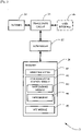
- FIG 2 is a block diagram illustrating the main components of the communication device 3 shown in Figure 1 .
- the communication device 3 may be an MTC device or a mobile (or 'cellular') telephone configured as a machine-type communication device.
- the communication device 3 comprises a transceiver circuit 31 which is operable to transmit signals to, and to receive signals from, the base station 5 via at least one antenna 33.
- the communication device 3 also includes a user interface 35 which allows a user to interact with the communication device 3. However this user interface 35 may be omitted for some MTC devices.
- the operation of the transceiver circuit 31 is controlled by a controller 37 in accordance with software stored in a memory 39.
- the software includes, among other things, an operating system 41, a communications control module 42, and an MTC module 45.
- the communications control module 42 controls communications between the communication device 3 and the base station 5 and/or other communication nodes (via the base station 5). As shown in Figure 2 , the communications control module 42 includes, amongst others, a narrowband module 43 and a HARQ module 44.
- the narrowband module 43 is responsible for identifying and using narrowbands within the system bandwidth.
- the HARQ module 44 is responsible for generating and sending, to the serving base station 5, appropriate acknowledgements (ACK/NACK) for downlink transmissions from the serving base station 5.
- ACK/NACK appropriate acknowledgements
- the HARQ module 44 may be configured to bundle acknowledgements and send a (single) 'bundled' ACK/ NACK for multiple downlink transmissions.
- the MTC module 45 is operable to carry out machine-type communication tasks. For example, the MTC module 45 may (e.g. periodically) receive data from a remote server (via the transceiver circuit 31) over resources allocated to the MTC device 3 by the base station 5. The MTC module 45 may also collect data for sending (e.g. periodically and/or upon detecting a trigger) to a remote server (via the transceiver circuit 31). The MTC module 45 may be configured to support high data rate transmissions (at least in some MTC applications).
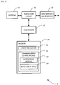
- FIG 3 is a block diagram illustrating the main components of the base station 5 shown in Figure 1 .
- the base station 5 comprises an E-UTRAN base station (eNB) comprising a transceiver circuit 51 which is operable to transmit signals to, and to receive signals from, the communication devices 3 via one or more antennas 53.
- the base station 5 is also operable to transmit signals to and to receive signals from a core network 7 via an appropriate core network interface 55 (such as an S1 interface).
- eNB E-UTRAN base station
- the operation of the transceiver circuit 51 is controlled by a controller 57 in accordance with software stored in a memory 59.
- the software includes, among other things, an operating system 61 and a communications control module 62.
- the communications control module 62 controls communications with the communication devices 3 (including any MTC devices).
- the communications control module 62 is also responsible for scheduling the resources to be used by the communication devices 3 served by this base station 5.
- the communications control module 62 includes, amongst others, a narrowband module 63 and a scheduling module 64.
- the narrowband module 63 is responsible for dividing the system bandwidth into narrowbands for communicating with (MTC) communication devices 3.
- the scheduling module 64 is responsible for scheduling transmissions for the communication devices 3 in the base station's cell, by generating and sending appropriately formatted control data (e.g. DCI) and by receiving and processing associated acknowledgements (including 'bundled' ACKs/NACKs for multiple downlink transmissions, when appropriate).
- the communication device 3 and the base station 5 are described for ease of understanding as having a number of discrete modules. Whilst these modules may be provided in this way for certain applications, for example where an existing system has been modified to implement the invention, in other applications, for example in systems designed with the inventive features in mind from the outset, these modules may be built into the overall operating system or code and so these modules may not be discernible as discrete entities.
- MTC devices may perform high data rate transmissions in LTE systems.
- higher/ flexible data rates may be achieved, by HARQ-ACK bundling (for HD-FDD in CE mode A) and/or by employing a larger maximum PDSCH/PUSCH channel bandwidth in connected mode (at least in CE mode A).
- HD-FDD Half Duplex FDD
- FD-FDD Full Duplex FDD
- each HD-FDD UE needs to listen to the control channel (i.e. MPDCCH) in one subframe (i.e. operating as a receiver only) in order to determine whether it is scheduled to transmit/receive in a subsequent subframe (or subframes) in the uplink/downlink direction.
- MPDCCH control channel
- a particular HD-FDD UE If a particular HD-FDD UE is scheduled for transmission (via an appropriately formatted control information over the MPDCCH), then it needs to change its HD-FDD operation to transmitting mode before it can send uplink data in the subframe(s) identified by the received control information. Once the scheduled data is transmitted, the communication device 3 changes back to receiver mode in order to monitor for further scheduling assignments.
- the main benefit of using such a HD-FDD type of operation is the reduced complexity (no duplex filter is needed) and associated lower cost of the communication device 3. This may be an important factor in case of at least some MTC devices.
- each HD-FDD UE e.g. MTC devices
- Ack/Nack HARQ feedback
- the HD-FDD UE is not expected to receive its downlink data over the last Orthogonal Frequency Division Multiplexing (OFDM) symbol(s) of its allocated downlink subframe that immediately precedes an uplink subframe (over which the HARQ feedback is to be transmitted).
- OFDM Orthogonal Frequency Division Multiplexing
- the HD-FDD UE uses the last OFDM symbol(s) of its scheduled downlink transmission for switching its transceiver to transmitter mode (in time before the start of the next uplink subframe).
- Figure 4 illustrates details of an exemplary HARQ bundling technique.
- the communication device 3 is configured to derive a single acknowledgement feedback by performing a logical "AND" operation for multiple respective ACKs/NACKs for multiple downlink subframes (where data transmissions in each subframe result in a single 'ACK' or 'NACK' for that subframe depending on whether or not the transmission was successful).
- the communication device 3 is configured to transmit an 'ACK' to the base station 5 if all associated downlink transmissions succeed, otherwise transmit a 'NACK' if one or more associated downlink transmissions fail.
- communication resources are allocated to the communication device 3 by transmitting an appropriately formatted DCI format over the MPDCCH 70.
- the DCI may be used to 'cross schedule' downlink data for the PDSCH 71 in the second subframe following a subframe in which the DCI format is transmitted.
- the communication device 3 is scheduled further downlink data (via a further DCI) via the MPDDCH 70 in the subframe following the PDSCH 71 (which further downlink data is transmitted in second subframe following the subframe in which the further DCI format is transmitted).
- the communication device 3 can beneficially avoid having to switch to HD-FDD transmitter mode until both downlink transmissions are complete, and still be able to provide sufficient feedback for both downlink transmissions (when bundling for two subframes).
- the bundled HARQ feedback (Ack/Nack) is transmitted via the PUCCH 72 (in an uplink subframe following the last scheduled downlink PDSCH 71). It will be appreciated that the bundled HARQ feedback may be sent in the first 'UL' subframe following the last scheduled downlink PDSCH 71 (if that subframe carries the PUCCH 72) although in Figure 4 the bundled HARQ feedback is sent in a later subframe.
- the communication device 3 falls into the fourth category of UEs (FeMTC devices), and it is equipped with a transceiver 31 that is capable of a HD-FDD operation.
- the communication device 3 may also fall into the first category of UEs (e.g. mobile telephone 3-1), and in some examples, into the second or third category of UEs (e.g. NB-IoT devices / (e)MTC devices).
- the communication device 3 may be operating without any or with only a minor coverage enhancement (referred to as 'CE mode A' operation).
- the base station 5 (using its scheduling module 64) is configured to schedule, for a particular communication device 3, downlink transmissions in a particular (single) downlink subframe using one DCI format (i.e. one DCI per every scheduled subframe).
- the base station 5 (scheduling module 64) generates and sends, over the MPDCCH 70 (or PDCCH in case of non-MTC UEs), a plurality of appropriately configured DCI formats, each DCI format indicating one respective subframe of the scheduled sequence of subframes (also indicating the allocated downlink resources, i.e. PRBs, within that subframe).
- the communication device 3 receives (using its receiver 31 in HD-FDD reception mode), the DCI formats by listening to the MPDCCH 70 and (using its communication control module 42) determines the downlink allocations (which subframes/PRBs) by processing the received DCI formats. Whilst still in HD-FDD reception mode, the communication device 3 receives, via the PDSCH 71, the downlink data in each downlink subframe indicated by an associated DCI format.
- the communication device 3 since HARQ bundling is used, the communication device 3 (using its HARQ module 44) generates and transmits (via the PUCCH 72) an 'ACK' if all scheduled downlink transmissions were received successfully, and generates and transmits an 'NACK' if one or more scheduled downlink transmissions failed to receive correctly.
- the mobile device 3 needs to send a bundled HARQ feedback via the PUCCH 72 in uplink subframe with index 'n', then the last scheduled downlink transmission to this particular communication device 3 is scheduled for the downlink subframe with index 'n-4'. Therefore, if the communication device 3 does not receive any DCI format after downlink subframe 'n-4', then it has enough time to switch to transmission mode before subframe 'n'.
- DCI downlink assignment index
- NACK HARQ feedback
- DAI Downlink Detection
- the DCI format may be configured to signal a counter indicates (combines) both the total number of assignments and the place of the current assignment in the sequence.
- the value '10' indicates a starting assignment
- the value '00' indicates any middle assignment
- the value '01' (or '11') indicates and end assignment (in a sequence of assignments). Therefore, in this case, '11' denotes a single scheduling assignment (both the start and the end of a 'sequence' of one assignment).
- the base station 5 (using its scheduling module 64) is configured to schedule, for a particular communication device 3, downlink transmissions in multiple downlink subframes using one DCI format (i.e. one DCI per sequence of scheduled subframes).
- the base station 5 (scheduling module 64) generates and sends, over the MPDCCH 70 (or PDCCH in case of non-MTC UEs), an appropriately configured DCI format identifying the scheduled sequence of subframes (also indicating the allocated downlink resources, i.e. PRBs, within each subframe of the sequence).
- the communication device 3 receives (using its receiver 31 in HD-FDD reception mode), the DCI format by listening to the MPDCCH 70 and (using its communications control module 42) determines the downlink allocations (which subframes/PRBs) by processing the received DCI format. Whilst still in HD-FDD reception mode, the communication device 3 receives, via the PDSCH 71, the downlink data in each downlink subframe indicated by the received DCI format.
- the communication device 3 receives a DCI format via the MPDCCH 70 in a downlink subframe, and this DCI format allocates, to the communication device 3, resources in four consecutive downlink subframes. Therefore, in this example, the communication device 3 (with its transceiver 31 in HD-FDD reception mode) attempts to receive downlink data over the assigned PDSCH 71 resources in the four subframes identified by the DCI format.
- the communication device 3 uses its HARQ module 44 to generate and transmits (via the PUCCH 72) an 'ACK' if all scheduled downlink transmissions were received successfully, and generates and transmits an 'NACK' if one or more scheduled downlink transmissions failed to receive correctly.
- the communication device 3 needs to send a bundled HARQ feedback via the PUCCH 72 in uplink subframe with index 'n', then the last scheduled downlink transmission to this particular communication device 3 is scheduled for the downlink subframe with index 'n-4'. Therefore, if the communication device 3 does not receive any DCI format after downlink subframe 'n-4', it still has enough time to switch to transmission mode before subframe 'n'.
- scheduling multiple subframes via a single DCI format makes it possible to avoid frequent switching from downlink-to-uplink subframes and also improves (effectively doubles) the downlink data rate compared to scheduling every subframe via a separate DCI format.
- the DCI format may be configured to indicate the number of subframes being scheduled to that particular communication device 3. It will be appreciated that appropriate signalling information may be included in the DCI format to indicate the number of subframes (e.g. 2 bits of signalling for indicating up to four subframes) scheduled for a particular communication device 3. In this case, when using 2 bits as an example, the signalled values may indicate the number of allocated subframes according to Table 2.
- the number of subframes scheduled for a particular communication device 3 may depend on, for example, channel conditions of that communication device 3, overall system load, requested quality of service, capability of the communication device, and/or the like.
- the base station 5 may be configured to implement one of the following possibilities (which may be different for different UEs):
- the base station 5 is able to schedule a relatively large amount of resources for a particular communication device 3, in an efficient and flexible manner, and still be able to determine whether any data needs to be re-transmitted to that communication device 3.
- Support for higher data rates may also be realised by configuring the base station 5 to operate the PDSCH/PUSCH with increased bandwidth (i.e. a bandwidth higher than 1.4 MHz), at least for HD-FDD transmissions for MTC devices (and other compatible user equipment) operating without any or with only a minor coverage enhancement (referred to as 'CE mode A' operation). It will be appreciated that the option of using an increased PDSCH/PUSCH bandwidth may be combined with the bundled HARQ feedback approach, if appropriate.
- the target peak data rates for unicast traffic should not be less than 3Mbps/2Mbps for DL/UL respectively (for FD-FDD).
- peak data rates would require at least twice the data rate that can be provided using the current eMTC specified UE bandwidth of 1.4MHz.
- the base station 5 may be configured to reuse legacy (i.e. pre-Rel-13) system bandwidths of 1.4MHz, 3MHz, and 5MHz for its narrowbands as well.
- legacy i.e. pre-Rel-13
- some MTC devices e.g. in the second and third UE categories
- the base station 5 may be configured to schedule MTC devices in the second and third UE categories only in those narrowbands that do not exceed 1.4 MHz and schedule more enhanced MTC devices (e.g. in the fourth UE category) and conventional UEs (in the first category) in any narrowband (preferably in the 3MHz and/or 5MHz narrowbands if a higher data rate is required).
- the base station 5 may be configured to aggregate multiple narrowbands (of 6RBs / 1.4MHz each) for more enhanced MTC devices (e.g. in the fourth UE category) and for conventional UEs (in the first category).
- transmissions for other MTC devices e.g. in the second and third UE categories
- can still be scheduled for a single narrowband i.e. without any aggregation of narrowbands.
- each compatible UE/MTC device may be configured to use a larger transmission or reception bandwidth whenever it needs a high data rate (for example two or more consecutive narrowbands may be aggregated to meet the data rate demands of a particular communication device 3).
- each communication device may be scheduled semi-statically or dynamically to use a particular radio frequency and a particular baseband bandwidth (e.g. higher than 1.4MHz but not exceeding the maximum bandwidth supported by that device).
- the base station 5 may aggregate multiple narrowbands, for a particular communication device 3, in a semi-static manner using radio resource control (RRC) signalling. If appropriate, the base station 5 can also change the UE bandwidth for the communication device 3 by changing the number of aggregated narrowbands.
- the resource allocation (by the scheduling module 64) may be based on the number of narrowbands configured by RRC signalling.
- the resource allocation indication may be given by, for example, the formula log 2 (N RB (N RB +1)/2) and/or the like. A benefit associated with this approach is that it can reduce the power consumption by the communication device 3.
- the base station 5 may be configured to aggregate multiple subbands of 5MHz each for compatible devices (e.g. enhanced MTC devices in the fourth UE category and also for conventional UEs in the first category).
- the system bandwidth may be divided into multiple 5MHz subbands where each subband has its own separate resource allocation.
- the base station 5 may be configured to indicate dynamically the index of an assigned subband and RBs within that subband to the communication devices being scheduled.
- the base station 5 may use dynamic signalling via the MPDCCH 70 (based on a variant of the DCI format) to indicate the bandwidth (i.e. the level of narrowband aggregation) allocated in that scheduling instance to a particular communication device 3 (denoted 'UE1' in Figure 7 ).
- the columns represent consecutive subframes and the rows represent narrowbands in the system bandwidth (each narrowband having a respective associated index between '0' and '7').
- the bandwidth of each narrowband (and hence that of the MPDCCH 70) is 6RBs (1.4MHz), i.e. the same as the narrowband bandwidth defined for Rel-13 eMTC.
- the resource allocation indication (e.g. given by the formula log 2 N RB (NR B +1)/2)) may thus be based on the number of narrowbands signalled in the DCI format.
- the DCI format includes information indicating the starting narrowband and the number of consecutive PRBs allocated in that scheduling instance to a particular communication device 3.
- the resource allocation indication e.g. given by the formula log 2 (N RB (N RB +1)/2)
- N RB N RB +1
- the base station 5 may be configured to signal the starting narrowband dynamically, for example, in order to enable frequency selective scheduling.
- the starting narrowband may be the narrowband which includes the starting PRB of the given resource allocation.
- the resource allocation for PDSCH/PUSCH may comprise the index of a starting narrowband and the number of contiguous RBs allocated for a given communication device 3.
- the resource allocation may be implemented, for example, by reusing a legacy eMTC resource allocation method, such as 'DCI Format 6-0A' which is defined in section 5.3.3.1.10 of 3GPP TS 36.212 V13.2.0. This re-used resource allocation is based on the following formula: ⁇ log 2 ⁇ N RB DL 6 ⁇ ⁇ + 5 bits
- 5 bits can represent more than 25RBs (5MHz), without considering the starting RB (which is automatically given by the index of the starting narrowband).
- the +5 bits of the resource allocation formula are given by ⁇ log 2 25 ⁇ for allocating a maximum bandwidth of 5MHz (25 RBs).
- this modified resource allocation method does not have an impact on the size of legacy Rel-13 eMTC resource allocations (such as DCI Format 6-0A).
- the DCI size for Rel-13 eMTC and FeMTC resource allocations will be same when applying the above resource allocation method.
- the following techniques may be used to determine which DCI format is being used by the serving base station 5 so that the communication device 3 is able to differentiate between the two DCI formats.
- the base station 5 (and communication devices 3) may be configured to use the (legacy) field "Frequency hopping flag - 1 bit" to differentiate between the two types of DCI formats.
- the base station 5 and communication devices 3 may be configured to use the (legacy) field "Frequency hopping flag - 1 bit" to differentiate between the two types of DCI formats.
- This is possible because communication devices 3 that support a larger bandwidth of PDSCH/PUSCH than 1.4MHz may either not require frequency hopping or, if frequency hopping is required, the frequency hopping can be enabled or disabled using only higher layers (RRC signalling) instead of using a DCI format dynamically.
- the base station 5 may be configured to use the field "Frequency hopping flag - 1 bit" to differentiate between the two types of DCI formats (rather than to indicate whether or not frequency hopping is employed).
- the "Frequency hopping flag - 1 bit" is set to a particular value (e.g. '1'), then it can be interpreted to indicate that the above described modified DCI format is being used, and when the flag is set to a different value (e.g. '0'), it can be interpreted to indicate that the legacy DCI format is being used (or vice versa).
- the base station 5 (and the communication device 3) may be configured to use the fields "Frequency hopping flag - 1 bit” and “Repetition number - 2 bits” to differentiate between the two types of DCI formats (legacy and modified). This is possible, because repetitions (configured via the "Repetition number - 2 bits” field) can achieve more diversity gain together with frequency hopping.
- the field "Frequency hopping flag - 1 bit” indicates frequency hopping only when repetitions are also configured for a particular communication device 3.
- the field "Frequency hopping flag - 1 bit” may be used for differentiating between the two DCI formats (e.g. in the manner described above for the first option).
- the larger bandwidth of PDSCH/PUSCH is only used when there is no repetition in time domain.
- the base station 5 may be configured to use legacy resource assignments for narrowband communication devices 3 but restrict the total assignment for a particular communication device 3 to a maximum of 25 RBs (5MHz).
- the PDSCH/PUSCH resource allocations can be based on the base station's system bandwidth (rather than the narrowband bandwidth). Accordingly, this allows reusing legacy resource allocation schemes such as downlink resource allocation 'Type 2' and uplink resource allocation 'Type 0' (with a total assignment not exceeding 25 RBs per UE).
- the following approach may be employed in order to determine the appropriate subframe in which PUCCH transmission starts for HARQ-ACK bundling (e.g. in CE mode A, in case of HD-FDD). This example may be applied for all cases of PUCCH transmissions (with and without repetition).
- the base station 5 transmits a number of data bundles (e.g. PDSCH bundle) to the communication device 3, in a sequence of downlink sub-frames.
- the communication device 3 is configured to provide a respective bundled ACK/NACK feedback for each data bundle.
- the communication device 3 and the base station 5 are able to determine an appropriate starting sub-frame, in which respective ACK/NACK feedback for the first PDSCH bundle is expected, based on the bundling configuration applicable for that particular communication device 3 (for example, based on the last sub-frame in which a last data bundle is transmitted, the number of data bundles, and whether or not transmission of the data bundles is repeated).
- the communication device 3 and the base station 5 have a common understanding of which ACK/NACK is transmitted in which sub-frame.
- the communication device 3 can proceed to transmit the ACK/NACK feedback for any further PDSCH bundle, in the correct sub-frame(s).
- the communication device 3 (e.g. MTC UE 3-2) is configured to transmit an appropriate HARQ-ACK response on the PUCCH for each PDSCH bundle in sequence, starting with an HARQ-ACK for the first received PDSCH bundle.
- the PUCCH transmissions span N abs_total PUCCH ⁇ N bundle N rep PUCCH consecutive subframes, including any non-BL/CE UL subframes where the communication device 3 postpones the PUCCH transmission in this example , if N rep PUCCH > 1 .
- N bundle is the number of bundles that the communication device 3 received (i.e.
- N rep PUCCH is the number of PUCCH repetitions for a single bundle (which is applicable to each bundle); and N abs_total PUCCH is the total number of absolute consecutive subframes (including any non-BL/CE UL subframes) that all PUCCH transmissions span.
- Figure 9 illustrates an exemplary way in which MTC device compatible narrowbands may be provided in the system shown in Figure 1 .
- 3GPP defined MTC specific narrowbands as follows:
- N RB DL and N RB UL stand for the number of PRBs in the system bandwidth (for downlink and uplink, respectively).
- each narrowband comprises six resource blocks, and there are some remaining resource blocks (less than six resource blocks) that are distributed evenly at the edges of the frequency bandwidth.
- the system bandwidth comprises a total of N RB DL PRBs , each PRB having a respective associated resource block index in the range ′ 0 ′ to ′ N RB DL - 1 ′ .
- the remaining resource blocks are divided into two 'partial narrowbands' each comprising one PRB (at the edges of the system bandwidth). It will be appreciated that, if appropriate, these remaining resource blocks may also be allocated to compatible MTC devices (or other user equipment). Alternatively, the remaining resource blocks may be allocated for use by other UEs (e.g. for non-MTC use) and/or for transmitting control data.
- the narrowbands index numbers facilitate efficient assignment of the narrowbands to MTC devices.
- the indexing is arranged in order of increasing PRB number.
- the partial narrowbands may also be provided with their own respective index numbers (e.g. for allocation to NB-IoT devices).
- eNB E-UTRAN base station
- HeNB home base stations
- LTE telecommunications system was described.
- Other communications nodes or devices may include user devices such as, for example, personal digital assistants, laptop computers, web browsers, etc.
- the base station and the communication device each include transceiver circuitry.
- this circuitry will be formed by dedicated hardware circuits.
- part of the transceiver circuitry may be implemented as software run by the corresponding controller.
- the software modules may be provided in compiled or un-compiled form and may be supplied to the base station or the communication device as a signal over a computer network, or on a recording medium. Further, the functionality performed by part or all of this software may be performed using one or more dedicated hardware circuits.
- functionality and/or modules described herein may be implemented using one or computer processing apparatus having one or more hardware computer processors programmed using appropriate software instructions to provide the required functionality (e.g. one or more computer processors forming part of the controllers described with reference to the Figures 2 or 3 ). It will be further appreciated that all or part of these functions may be implemented in hardware as dedicated circuitry for example using one or more dedicated integrated circuits such as an application specific integrated circuit (ASIC) or the like.
- ASIC application specific integrated circuit
- controllers referred to in the description of the UE and base station may comprise any suitable controller such as, for example an analogue or digital controller.
- Each controller may comprise any suitable form of processing circuitry including (but not limited to), for example: one or more hardware implemented computer processors; microprocessors; central processing units (CPUs); arithmetic logic units (ALUs); input/output (IO) circuits; internal memories / caches (program and/or data); processing registers; communication buses (e.g. control, data and/or address buses); direct memory access (DMA) functions; hardware or software implemented counters, pointers and/or timers; and/or the like.
- CPUs central processing units
- ALUs arithmetic logic units
- IO input/output circuits
- internal memories / caches program and/or data
- processing registers e.g. control, data and/or address buses
- DMA direct memory access
- machine-type communication devices and mobile telephones are described.
- mobile telephones and similar user equipment
- the mobile telephone 3-1 may include (and/or provide the functionality of) the MTC module 45.
- each communication device may support one or more MTC applications.
- MTC applications Some examples of MTC applications are listed in the following table (source: 3GPP TS 22.368 V13.1.0, Annex B). This list is not exhaustive and is intended to be indicative of the scope of machine-type communication applications. [Table 4] Service Area MTC applications Security Surveillance systems Backup for landline Control of physical access (e.g.
- the ACK/NACK indication may comprise an acknowledgement (ACK), and when data transmitted to the machine type communication device in one subframe of the plurality of subframes has not been received successfully the ACK/NACK indication may comprise an non-acknowledgement (NACK).
- ACK acknowledgement
- NACK non-acknowledgement
- the control information may comprise a single downlink control indication for assigning communication resources in each of the plurality of subframes.
- the plurality of subframes may comprise a plurality of consecutive subframes within a single narrowband.
- the control information may comprise, for each subframe of the plurality of subframes, a respective downlink control information (DCI) format for allocating a set of PRBs in that subframe.
- the control information may comprises, for each subframe, information (e.g. a downlink assignment index, DAI) indicating a total or remaining number of subframes in which communication resources are allocated for the communication device before the communication devices is required to provide feedback.
- DCI downlink control information
- the control information may include information identifying at least one of: a starting subframe of the plurality of subframes; an ending subframe of the plurality of subframes; a number of subframes in the plurality of subframes.
- the subframe in which feedback is sent may be a predetermined number of subframes (e.g. 4) following the last of the plurality of subframes.
- the feedback may comprise a bundled Hybrid Automatic Repeat Request, HARQ, feedback.
- the transceiver of the base station may be operable to transmit (and the transceiver of the machine type communication device may be operable to receive) the generated control information using a machine-type communication (MTC) specific Physical Downlink Control Channel (MPDCCH).
- MTC machine-type communication
- MPDCCH Physical Downlink Control Channel
- the base station may comprise a base station of a long term evolution (LTE) radio access network.
- the transceiver of the machine type communication device may be operable to communicate using a reduced bandwidth compared to the cell bandwidth.
- control information may comprise one downlink control indication for assigning communication resources in each of a plurality of subframes; the transceiver may be operable to receive, from the machine type communication device ACK/NACK feedback for data transmitted to the machine type communication device; and the ACK/NACK feedback may comprise a single ACK/NACK indication for acknowledging data transmitted in a plurality of subframes.
- the control information may comprise one downlink control indication for assigning communication resources in each of a plurality of narrowbands in the same subframe; and the plurality of narrowbands may comprise a plurality of contiguous narrowbands.
- the communication resources may comprise physical resource blocks (PRBs) and the control information may identify a starting PRB, and a total number of contiguous PRBs assigned to the communication device from the starting PRB.
- PRBs physical resource blocks
- the downlink control indication may reuse a legacy DCI Format (e.g. a modified DCI Format 6-0A) for the assigning of communication resources in each of a plurality of narrowbands in the same subframe.
- the reused legacy DCI Format uses the formula ⁇ log 2 n ⁇ for allocating a maximum of 'n' contiguous PRBs.
- the controller may be operable to differentiate between use of the legacy DCI Format for the assigning of communication resources in each of a plurality of narrowbands in the same subframe and use of the legacy DCI Format for legacy purposes, by using different respective settings of at least one of a (legacy) frequency hopping parameter and a (legacy) repetition number parameter.
- Each narrowband may cover a different respective frequency range comprising a predetermined (preferably 6 or 25) number of physical resource blocks (PRBs).
- PRBs physical resource blocks
- the data may be transmitted in a number of data bundles in sequence (e.g. PDSCH bundles), each data bundle being transmitted in a sequence of downlink sub-frames.
- the machine type communication device may be operable to transmit to the base station ACK/NACK feedback, comprising respective ACK/NACK feedback for each bundle.
- the machine type communication device and the base station may be operable to determine a starting sub-frame in which respective ACK/NACK feedback for a first PDSCH bundle is expected based on the last sub-frame in which a last data bundle is transmitted, the number of data bundles, and whether or not transmission of the data bundles is repeated.
- the starting sub-frame may be determined based on the following formula: n ⁇ 2 if N rep PUCCH > 1 and N bundle > 1 ; and n + 1 ⁇ N bundle otherwise ; wherein 'n' is the fourth subframe following a last sub-frame in which the last data bundle is transmitted; N bundle is the number of data bundles; and N rep PUCCH is a number of times a data bundle is transmitted.
- a base station for a communication system comprising:
- a base station for a communication system comprising:
- control information comprises a single downlink control indication for assigning communication resources in each of the plurality of subframes.
- control information comprises, for each subframe of the plurality of subframes, a respective downlink control information, DCI, format for allocating a set of physical resource blocks, PRBs, in that subframe.
- control information comprises, for each subframe, information (e.g. a downlink assignment index, DAI) indicating a total or remaining number of subframes in which communication resources are allocated for the communication device before the communication devices is required to provide feedback.
- information e.g. a downlink assignment index, DAI
- control information includes information identifying at least one of: a starting subframe of the plurality of subframes; an ending subframe of the plurality of subframes; a number of subframes in the plurality of subframes.
- Supplementary note 10 The base station according to any one of Supplementary notes 1 to 9, wherein the transceiver is operable to transmit the generated control information using a machine-type communication, MTC, specific Physical Downlink Control Channel, MPDCCH.
- MTC machine-type communication
- MPDCCH Physical Downlink Control Channel
- Supplementary note 11 The base station according to any one of Supplementary notes 1 to 10, wherein the subframe in which feedback is sent is a predetermined number of subframes (e.g. 4) following the last of the plurality of subframes.
- Supplementary note 12 The base station according to any one of Supplementary notes 1 to 11, wherein the feedback comprises a bundled Hybrid Automatic Repeat Request, HARQ, feedback.
- Supplementary note 13 The base station according to any one of Supplementary notes 1 to 12, comprising a base station of a long term evolution, LTE, radio access network.
- a base station for a communication system comprising:
- control information comprises one downlink control indication for assigning communication resources in each of a plurality of subframes; wherein the transceiver is operable to receive, from the machine type communication device ACK/ NACK feedback for data transmitted to the machine type communication device; and wherein the ACK/NACK feedback comprises a single ACK/NACK indication for acknowledging data transmitted in a plurality of subframes.
- control information comprises one downlink control indication for assigning communication resources in each of a plurality of narrowbands in the same subframe; and wherein the plurality of narrowbands comprises a plurality of contiguous narrowbands.
- Supplementary note 18 The base station according to Supplementary note 15, wherein the downlink control indication reuses a legacy DCI Format (e.g. a modified DCI Format 6-0A) for the assigning of communication resources in each of a plurality of narrowbands in the same subframe.
- a legacy DCI Format e.g. a modified DCI Format 6-0A
- each narrowband covers a different respective frequency range comprising a predetermined (preferably 6 or 25) number of physical resource blocks, PRBs.
- the base station according to Supplementary note 3 or 14, wherein the data is transmitted in a number of data bundles in sequence (e.g. physical downlink shared channel 'PDSCH' bundles), each data bundle being transmitted in a sequence of downlink sub-frames; wherein the transceiver is operable to receive ACK/ NACK feedback, comprising respective ACK/NACK feedback for each bundle; and wherein the controller is operable to determine a starting sub-frame in which respective ACK/NACK feedback for a first PDSCH bundle is expected based on the last sub-frame in which a last data bundle is transmitted, the number of data bundles, and whether or not transmission of the data bundles is repeated.
- the data bundles in sequence e.g. physical downlink shared channel 'PDSCH' bundles
- the transceiver is operable to receive ACK/ NACK feedback, comprising respective ACK/NACK feedback for each bundle
- the controller is operable to determine a starting sub-frame in which respective ACK/NACK feedback for a first PDSCH
- Supplementary note 24 The base station according to any one of Supplementary notes 14 to 23, wherein the transceiver is operable to transmit the generated control information using a machine-type communication, MTC, specific Physical Downlink Control Channel, MPDCCH.
- MTC machine-type communication
- MPDCCH Physical Downlink Control Channel
- a machine type communication device for a communication system comprising: a transceiver operable to receive:
- a machine type communication device for a communication system comprising:
- control information comprises a single downlink control indication for assigning communication resources in each of the plurality of subframes.
- control information comprises, for each subframe of the plurality of subframes, a respective downlink control information, DCI, format for allocating a set of physical resource blocks, PRBs, in that subframe.
- control information comprises, for each subframe, information (e.g. a downlink assignment index, DAI) indicating a total or remaining number of subframes in which communication resources are allocated for the communication device before the communication devices is required to provide feedback.
- information e.g. a downlink assignment index, DAI
- control information includes information identifying at least one of: a starting subframe of the plurality of subframes; an ending subframe of the plurality of subframes; a number of subframes in the plurality of subframes.
- Supplementary note 35 The machine type communication device according to any one of Supplementary notes 27 to 34, wherein the subframe in which feedback is sent is a predetermined number of subframes (e.g. 4) following the last of the plurality of subframes.
- a machine type communication device for a communication system comprising: a transceiver operable to receive, from a base station:
- control information comprises one downlink control indication for assigning communication resources in each of a plurality of subframes; wherein the transceiver is operable to transmit, to the base station ACK/NACK feedback for data transmitted by the base station to the machine type communication device; and wherein the ACK/NACK feedback comprises a single ACK/NACK indication for acknowledging data transmitted in a plurality of subframes.
- control information comprises one downlink control indication for assigning communication resources in each of a plurality of narrowbands in the same subframe; and wherein the plurality of narrowbands comprises a plurality of contiguous narrowbands.
- each narrowband covers a different respective frequency range comprising a predetermined (preferably 6 or 25) number of physical resource blocks, PRBs.
- (Supplementary note 45) A system comprising: the base station according to any one of Supplementary notes 1 to 24; and the machine type communication device according to any one of Supplementary notes 25 to 44.
- a method performed by a base station of a communication system comprising: generating control information for assigning communication resources for transmitting data to a machine type communication device, wherein the control information comprises one downlink control indication for assigning at least one of: (i) communication resources in each of a plurality of subframes; and (ii) communication resources in each of a plurality of narrowbands in the same subframe; and transmitting the generated control information to the machine type communication device, to transmit data to the machine type communication device using the assigned communication resources.
- a method performed by a communication device of a communication system comprising: receiving, from a base station:
- a computer implementable instructions product comprising computer implementable instructions for causing a programmable communications device to perform the method of any one of Supplementary notes 46 to 51.
Landscapes
- Engineering & Computer Science (AREA)
- Signal Processing (AREA)
- Computer Networks & Wireless Communication (AREA)
- Mobile Radio Communication Systems (AREA)
Applications Claiming Priority (5)
| Application Number | Priority Date | Filing Date | Title |
|---|---|---|---|
| GB1613710.1A GB2552947A (en) | 2016-08-09 | 2016-08-09 | Communication System |
| GB1616492.3A GB2553007A (en) | 2016-08-09 | 2016-09-28 | Communication system |
| GB1701845.8A GB2553011A (en) | 2016-08-09 | 2017-02-03 | Communication system |
| EP17757899.4A EP3497842B1 (de) | 2016-08-09 | 2017-08-08 | Kommunikationssystem |
| PCT/JP2017/028702 WO2018030379A1 (en) | 2016-08-09 | 2017-08-08 | Communication system |
Related Parent Applications (2)
| Application Number | Title | Priority Date | Filing Date |
|---|---|---|---|
| EP17757899.4A Division EP3497842B1 (de) | 2016-08-09 | 2017-08-08 | Kommunikationssystem |
| EP17757899.4A Division-Into EP3497842B1 (de) | 2016-08-09 | 2017-08-08 | Kommunikationssystem |
Publications (2)
| Publication Number | Publication Date |
|---|---|
| EP4037217A2 true EP4037217A2 (de) | 2022-08-03 |
| EP4037217A3 EP4037217A3 (de) | 2022-10-19 |
Family
ID=57539785
Family Applications (2)
| Application Number | Title | Priority Date | Filing Date |
|---|---|---|---|
| EP22153782.2A Pending EP4037217A3 (de) | 2016-08-09 | 2017-08-08 | Kommunikationssystem |
| EP17757899.4A Active EP3497842B1 (de) | 2016-08-09 | 2017-08-08 | Kommunikationssystem |
Family Applications After (1)
| Application Number | Title | Priority Date | Filing Date |
|---|---|---|---|
| EP17757899.4A Active EP3497842B1 (de) | 2016-08-09 | 2017-08-08 | Kommunikationssystem |
Country Status (6)
| Country | Link |
|---|---|
| US (2) | US11284235B2 (de) |
| EP (2) | EP4037217A3 (de) |
| JP (4) | JP6702503B2 (de) |
| CN (2) | CN109565366B (de) |
| GB (3) | GB2552947A (de) |
| WO (1) | WO2018030379A1 (de) |
Families Citing this family (19)
| Publication number | Priority date | Publication date | Assignee | Title |
|---|---|---|---|---|
| CN105722239A (zh) * | 2016-02-05 | 2016-06-29 | 宇龙计算机通信科技(深圳)有限公司 | 一种调度指令的检测方法和终端 |
| JP6559355B2 (ja) * | 2016-08-10 | 2019-08-14 | 京セラ株式会社 | 移動通信方法、基地局、プロセッサ及びユーザ装置 |
| CN107733576A (zh) * | 2016-08-11 | 2018-02-23 | 株式会社Ntt都科摩 | 发送混合自动重复请求反馈信息的方法和用户设备 |
| CN107733622B (zh) * | 2016-08-12 | 2022-01-11 | 中兴通讯股份有限公司 | 资源分配和确定的方法及装置 |
| CN107872779B (zh) * | 2016-09-27 | 2020-12-01 | 中兴通讯股份有限公司 | 资源分配方法及装置 |
| US10484147B2 (en) * | 2017-02-03 | 2019-11-19 | Qualcomm Incorporated | Techniques for enhanced machine type communication acknowledgment bundling |
| WO2019047171A1 (zh) * | 2017-09-08 | 2019-03-14 | Oppo广东移动通信有限公司 | 一种信道跳频的确定方法及装置、计算机存储介质 |
| EP3664315B1 (de) | 2017-09-08 | 2022-04-27 | Guangdong Oppo Mobile Telecommunications Corp., Ltd. | Verfahren und vorrichtung zur bestimmung von frequenzsprüngen eines kanals und computerspeichermedium |
| KR102169260B1 (ko) | 2017-09-08 | 2020-10-26 | 아서스테크 컴퓨터 인코포레이션 | 무선 통신 시스템에서 빔 포밍 전송을 고려한 무허가 스펙트럼에서의 채널 사용 방법 및 장치 |
| US10707915B2 (en) * | 2017-12-04 | 2020-07-07 | Qualcomm Incorporated | Narrowband frequency hopping mechanisms to overcome bandwidth restrictions in the unlicensed frequency spectrum |
| CN110324126B (zh) * | 2018-03-30 | 2020-12-04 | 电信科学技术研究院有限公司 | 一种数据传输方法、终端设备及网络设备 |
| CN109196936B (zh) * | 2018-08-07 | 2021-12-07 | 北京小米移动软件有限公司 | 一种资源分配指示方法及装置、基站及终端 |
| EP3836443A4 (de) * | 2018-08-08 | 2021-08-18 | Beijing Xiaomi Mobile Software Co., Ltd. | Verfahren und vorrichtung für rückkopplung von hybriden automatischen wiederholungsanforderungen (harq) |
| WO2020029130A1 (zh) * | 2018-08-08 | 2020-02-13 | 北京小米移动软件有限公司 | 混合自动重传请求harq反馈方法及装置 |
| US12301355B2 (en) * | 2019-03-28 | 2025-05-13 | Apple Inc. | Indication of the number of repetitions for dci format 3/3A for EMTC |
| CN111865506B (zh) * | 2019-04-30 | 2023-12-12 | 华为技术有限公司 | 半静态码本生成的方法和通信装置 |
| WO2021030947A1 (en) | 2019-08-16 | 2021-02-25 | Qualcomm Incorporated | Bundling and timeline determination for multiple transport blocks scheduled by a single downlink control information message |
| US20210235441A1 (en) * | 2020-01-24 | 2021-07-29 | Qualcomm Incorporated | Control resource configurations |
| CN113328834B (zh) | 2020-02-28 | 2025-03-14 | 华为技术有限公司 | 一种通信方法及装置 |
Family Cites Families (31)
| Publication number | Priority date | Publication date | Assignee | Title |
|---|---|---|---|---|
| US9084277B2 (en) * | 2007-05-04 | 2015-07-14 | Qualcomm Incorporated | Method and apparatus for UL ACK allocation |
| CN101567775B (zh) | 2008-04-25 | 2012-04-25 | 电信科学技术研究院 | 传输上行数据的方法、发送端设备和接收端设备 |
| WO2009134179A1 (en) * | 2008-04-28 | 2009-11-05 | Telefonaktiebolaget L M Ericsson (Publ) | Method and arrangement in a telecommunication system with signalling of assigned data packets in a bundling window |
| JP2011142532A (ja) * | 2010-01-08 | 2011-07-21 | Sharp Corp | 無線通信システム、基地局装置、移動局装置、無線通信方法および集積回路 |
| US9083520B2 (en) * | 2010-09-15 | 2015-07-14 | Lg Electronics Inc. | Apparatus for transmitting control information in a wireless communication system and method thereof |
| EP3621390B1 (de) * | 2010-11-16 | 2024-10-09 | Sun Patent Trust | Kommunikationsvorrichtung und srs-übertragungssteuerungsverfahren |
| US9225503B2 (en) * | 2011-05-02 | 2015-12-29 | Lg Electronics Inc. | Method for transmitting/receiving data in wireless communication system and base station for same |
| WO2013015637A2 (ko) | 2011-07-26 | 2013-01-31 | 엘지전자 주식회사 | 상향링크 신호 전송방법 및 사용자기기, 상향링크 신호 수신방법 및 기지국 |
| JP5847525B2 (ja) * | 2011-10-11 | 2016-01-27 | 株式会社Nttドコモ | 無線通信端末、基地局装置、無線通信システム及び無線通信方法 |
| KR20130049573A (ko) * | 2011-11-04 | 2013-05-14 | 삼성전자주식회사 | 제어 신호 송수신 방법 및 장치 |
| WO2013082784A1 (en) * | 2011-12-08 | 2013-06-13 | Renesas Mobile Corporation | Resource allocation by component carrier sub-bands |
| KR20130107855A (ko) * | 2012-03-23 | 2013-10-02 | 주식회사 팬택 | 협대역 단말을 위한 제어채널 구성장치 및 방법 |
| CN103684675B (zh) * | 2012-09-24 | 2018-10-02 | 夏普株式会社 | 针对窄带用户设备的下行链路控制信息发送/接收方法 |
| CN104769857B (zh) * | 2012-11-01 | 2018-05-22 | Lg 电子株式会社 | 在无线通信系统中支持设备特性的调度组的方法和装置 |
| EP4207668A1 (de) * | 2013-01-11 | 2023-07-05 | InterDigital Patent Holdings, Inc. | System und verfahren zur adaptiven modulation |
| CN103929266B (zh) * | 2013-01-15 | 2019-08-09 | 中兴通讯股份有限公司 | 控制信道传输、传输处理方法及装置、网络侧设备、终端 |
| US9306721B2 (en) * | 2013-03-15 | 2016-04-05 | Google Technology Holdings LLC | Method and apparatus for device-to-device communication |
| US9001666B2 (en) * | 2013-03-15 | 2015-04-07 | Twilio, Inc. | System and method for improving routing in a distributed communication platform |
| US9924376B2 (en) * | 2013-06-21 | 2018-03-20 | Lg Electronics Inc. | Method for enhancing coverage of user equipment and an apparatus using the same |
| EP2897318B1 (de) * | 2014-01-21 | 2017-09-06 | Panasonic Intellectual Property Corporation of America | Verbesserungen der TDD-Uplink/Downlink-Konfiguration |
| US10411838B2 (en) * | 2014-01-23 | 2019-09-10 | Qualcomm Incorporated | Coverage enhancements with carrier aggregation |
| EP2919534B1 (de) * | 2014-03-12 | 2019-03-06 | Panasonic Intellectual Property Corporation of America | Leistungsreservenbenachrichtigung für MTC-Geräte in verbessertem Abdeckungsmodus |
| WO2016121911A1 (ja) * | 2015-01-29 | 2016-08-04 | 株式会社Nttドコモ | 無線基地局、ユーザ端末及び無線通信方法 |
| US11218254B2 (en) * | 2015-01-29 | 2022-01-04 | Samsung Electronics Co., Ltd | Method and apparatus for transmitting/receiving HARQ-ACK signal in wireless communication system supporting carrier aggregation |
| GB2540628A (en) * | 2015-07-24 | 2017-01-25 | Fujitsu Ltd | Control messages in wireless communication |
| JP6092347B1 (ja) * | 2015-11-05 | 2017-03-08 | 株式会社Nttドコモ | ユーザ端末、無線基地局及び無線通信方法 |
| CN106714320B (zh) * | 2015-11-16 | 2019-07-05 | 电信科学技术研究院 | 一种下行控制信息dci传输方法及装置 |
| US10447459B2 (en) * | 2016-03-10 | 2019-10-15 | Qualcomm Incorporated | HD-FDD communication having improved peak data rates |
| EP3226456B1 (de) * | 2016-04-01 | 2020-06-03 | Panasonic Intellectual Property Corporation of America | Asynchrones datenneuübertragungsprotokoll |
| US10687319B2 (en) * | 2016-08-08 | 2020-06-16 | Comcast Cable Communications, Llc | Group power control for a secondary cell |
| WO2018087734A1 (en) * | 2016-11-14 | 2018-05-17 | Telefonaktiebolaget L M Ericsson (Publ) | Resource allocation for bandwidth limited operation |
-
2016
- 2016-08-09 GB GB1613710.1A patent/GB2552947A/en not_active Withdrawn
- 2016-09-28 GB GB1616492.3A patent/GB2553007A/en not_active Withdrawn
-
2017
- 2017-02-03 GB GB1701845.8A patent/GB2553011A/en not_active Withdrawn
- 2017-08-08 EP EP22153782.2A patent/EP4037217A3/de active Pending
- 2017-08-08 WO PCT/JP2017/028702 patent/WO2018030379A1/en not_active Ceased
- 2017-08-08 CN CN201780048777.7A patent/CN109565366B/zh active Active
- 2017-08-08 US US16/323,686 patent/US11284235B2/en active Active
- 2017-08-08 JP JP2019506202A patent/JP6702503B2/ja active Active
- 2017-08-08 CN CN202210193028.6A patent/CN114679709A/zh active Pending
- 2017-08-08 EP EP17757899.4A patent/EP3497842B1/de active Active
-
2020
- 2020-04-28 JP JP2020079614A patent/JP7006721B2/ja active Active
-
2021
- 2021-12-28 JP JP2021214354A patent/JP2022043270A/ja active Pending
-
2022
- 2022-02-04 US US17/592,649 patent/US12015972B2/en active Active
-
2023
- 2023-05-23 JP JP2023084522A patent/JP2023106535A/ja active Pending
Also Published As
| Publication number | Publication date |
|---|---|
| US20190174283A1 (en) | 2019-06-06 |
| CN109565366A (zh) | 2019-04-02 |
| JP6702503B2 (ja) | 2020-06-03 |
| CN109565366B (zh) | 2022-03-11 |
| GB2553007A (en) | 2018-02-21 |
| JP7006721B2 (ja) | 2022-01-24 |
| GB2552947A (en) | 2018-02-21 |
| JP2020120412A (ja) | 2020-08-06 |
| US11284235B2 (en) | 2022-03-22 |
| JP2022043270A (ja) | 2022-03-15 |
| JP2023106535A (ja) | 2023-08-01 |
| GB2553011A (en) | 2018-02-21 |
| EP4037217A3 (de) | 2022-10-19 |
| JP2019523619A (ja) | 2019-08-22 |
| EP3497842A1 (de) | 2019-06-19 |
| US20220159435A1 (en) | 2022-05-19 |
| EP3497842B1 (de) | 2022-03-02 |
| GB201616492D0 (en) | 2016-11-09 |
| GB201701845D0 (en) | 2017-03-22 |
| WO2018030379A1 (en) | 2018-02-15 |
| CN114679709A (zh) | 2022-06-28 |
| US12015972B2 (en) | 2024-06-18 |
Similar Documents
| Publication | Publication Date | Title |
|---|---|---|
| US12015972B2 (en) | Communication system | |
| US11778644B2 (en) | Communication system | |
| US10772088B2 (en) | Control channels for wireless communication | |
| KR101875253B1 (ko) | 다중 셀 통신 네트워크에서의 제어 타이밍 구성 할당을 위한 기지국, 사용자 장비 및 이들에서의 방법 | |
| EP3251452B1 (de) | Uplink-steuerinformationsübertragungsverfahren und -vorrichtung | |
| EP3348103B1 (de) | Verfahren zur anzeige der zugewiesenen ressourcen für eine harq-nachricht in einem direktzugriffsverfahren für ein schmalbandiges endgerät mit geringer komplexität | |
| CN102025467B (zh) | 一种反馈信息的传输方法及传输装置 | |
| EP3282619B1 (de) | Informationsübertragungsverfahren und -vorrichtung | |
| US20210160919A1 (en) | Method and apparatus for data transmission | |
| EP3863210A1 (de) | Verfahren und vorrichtung zum empfangen von downlink-datenübertragungen | |
| EP2995027B1 (de) | Verfahren, benutzervorrichtung und funknetzwerkknoten für harq-ack/nack-bündelung auf pusch in einem dynamischen tdd-system | |
| CN106804116B (zh) | 一种反馈信息的传输方法和基站以及用户设备 | |
| EP3494745B1 (de) | Kommunikationssystem zur handhabung von uplink-frequenzneueinstellungskapazitäten von benutzergeräten | |
| EP4482239A2 (de) | Kommunikationssystem | |
| CN107925543A (zh) | 用于ecc中的多传输时间区间准予支持的重复下行链路准予设计 |
Legal Events
| Date | Code | Title | Description |
|---|---|---|---|
| PUAI | Public reference made under article 153(3) epc to a published international application that has entered the european phase |
Free format text: ORIGINAL CODE: 0009012 |
|
| STAA | Information on the status of an ep patent application or granted ep patent |
Free format text: STATUS: REQUEST FOR EXAMINATION WAS MADE |
|
| 17P | Request for examination filed |
Effective date: 20220127 |
|
| AC | Divisional application: reference to earlier application |
Ref document number: 3497842 Country of ref document: EP Kind code of ref document: P |
|
| AK | Designated contracting states |
Kind code of ref document: A2 Designated state(s): AL AT BE BG CH CY CZ DE DK EE ES FI FR GB GR HR HU IE IS IT LI LT LU LV MC MK MT NL NO PL PT RO RS SE SI SK SM TR |
|
| PUAL | Search report despatched |
Free format text: ORIGINAL CODE: 0009013 |
|
| AK | Designated contracting states |
Kind code of ref document: A3 Designated state(s): AL AT BE BG CH CY CZ DE DK EE ES FI FR GB GR HR HU IE IS IT LI LT LU LV MC MK MT NL NO PL PT RO RS SE SI SK SM TR |
|
| RIC1 | Information provided on ipc code assigned before grant |
Ipc: H04W 4/00 20180101ALI20220913BHEP Ipc: H04L 1/16 20060101AFI20220913BHEP |
|
| RBV | Designated contracting states (corrected) |
Designated state(s): AL AT BE BG CH CY CZ DE DK EE ES FI FR GB GR HR HU IE IS IT LI LT LU LV MC MK MT NL NO PL PT RO RS SE SI SK SM TR |
|
| STAA | Information on the status of an ep patent application or granted ep patent |
Free format text: STATUS: EXAMINATION IS IN PROGRESS |
|
| 17Q | First examination report despatched |
Effective date: 20231208 |