EP4036679B1 - Autonomer roboter, fahrtstreckenplanungsverfahren und vorrichtung dafür sowie speichermedium - Google Patents
Autonomer roboter, fahrtstreckenplanungsverfahren und vorrichtung dafür sowie speichermedium Download PDFInfo
- Publication number
- EP4036679B1 EP4036679B1 EP20867377.2A EP20867377A EP4036679B1 EP 4036679 B1 EP4036679 B1 EP 4036679B1 EP 20867377 A EP20867377 A EP 20867377A EP 4036679 B1 EP4036679 B1 EP 4036679B1
- Authority
- EP
- European Patent Office
- Prior art keywords
- slope
- area
- autonomous robot
- working area
- target working
- Prior art date
- Legal status (The legal status is an assumption and is not a legal conclusion. Google has not performed a legal analysis and makes no representation as to the accuracy of the status listed.)
- Active
Links
Images


Classifications
-
- G—PHYSICS
- G05—CONTROLLING; REGULATING
- G05D—SYSTEMS FOR CONTROLLING OR REGULATING NON-ELECTRIC VARIABLES
- G05D1/00—Control of position, course, altitude or attitude of land, water, air or space vehicles, e.g. using automatic pilots
- G05D1/02—Control of position or course in two dimensions
- G05D1/021—Control of position or course in two dimensions specially adapted to land vehicles
- G05D1/0212—Control of position or course in two dimensions specially adapted to land vehicles with means for defining a desired trajectory
- G05D1/0219—Control of position or course in two dimensions specially adapted to land vehicles with means for defining a desired trajectory ensuring the processing of the whole working surface
-
- G—PHYSICS
- G05—CONTROLLING; REGULATING
- G05D—SYSTEMS FOR CONTROLLING OR REGULATING NON-ELECTRIC VARIABLES
- G05D1/00—Control of position, course, altitude or attitude of land, water, air or space vehicles, e.g. using automatic pilots
- G05D1/0088—Control of position, course, altitude or attitude of land, water, air or space vehicles, e.g. using automatic pilots characterized by the autonomous decision making process, e.g. artificial intelligence, predefined behaviours
-
- G—PHYSICS
- G05—CONTROLLING; REGULATING
- G05D—SYSTEMS FOR CONTROLLING OR REGULATING NON-ELECTRIC VARIABLES
- G05D1/00—Control of position, course, altitude or attitude of land, water, air or space vehicles, e.g. using automatic pilots
- G05D1/02—Control of position or course in two dimensions
- G05D1/021—Control of position or course in two dimensions specially adapted to land vehicles
- G05D1/0268—Control of position or course in two dimensions specially adapted to land vehicles using internal positioning means
- G05D1/0274—Control of position or course in two dimensions specially adapted to land vehicles using internal positioning means using mapping information stored in a memory device
-
- G—PHYSICS
- G05—CONTROLLING; REGULATING
- G05D—SYSTEMS FOR CONTROLLING OR REGULATING NON-ELECTRIC VARIABLES
- G05D1/00—Control of position, course, altitude or attitude of land, water, air or space vehicles, e.g. using automatic pilots
- G05D1/20—Control system inputs
- G05D1/22—Command input arrangements
- G05D1/221—Remote-control arrangements
- G05D1/227—Handing over between remote control and on-board control; Handing over between remote control arrangements
-
- G—PHYSICS
- G05—CONTROLLING; REGULATING
- G05D—SYSTEMS FOR CONTROLLING OR REGULATING NON-ELECTRIC VARIABLES
- G05D1/00—Control of position, course, altitude or attitude of land, water, air or space vehicles, e.g. using automatic pilots
- G05D1/60—Intended control result
- G05D1/648—Performing a task within a working area or space, e.g. cleaning
Definitions
- This specification relates to the field of robotic technologies, and in particular, to an autonomous robot, a walking path planning method and apparatus therefor, and a storage medium.
- An autonomous robot (also referred to as a self-moving robot) is a robot that has a body provided with various necessary sensors and controllers and can independently complete a particular task without external manual information input and control during operation. That is, the autonomous robot can move autonomously to perform a work task in a working area.
- the autonomous robot In a full-coverage working mode, the autonomous robot generally moves along a planned full-coverage walking path to work.
- a path planning algorithm based on an ox-turning method (a square wave-shaped path) is widely used in actual production for its simple principle and easy implementation.
- a working area is generally flat by default.
- a work overlap ratio between adjacent path segments is fixed, and a coverage of full-coverage work can be ensured.
- the entire working area or a part thereof may always be uneven or have a slope.
- a work overlap ratio between adjacent path segments generally changes, the autonomous robot tends to miss a working area, and a work coverage ratio of the autonomous robot in the full-coverage mode is further likely to be affected.
- US2019243386A discloses a moving robot that includes: a body defining an exterior; a traveling unit configured to move the body against a travel surface; an operation unit disposed in the body and configured to perform a predetermined operation; a tilt information acquisition sensor configured to acquire tilt information on a tilt of the travel surface; and a controller configured to, when target movement direction being preset irrespective of an inclination of the travel surface crosses an upward inclination direction of the travel surface, control a heading direction, which is a direction of a traveling force (Fh) preset to be applied by the traveling unit to the body, to be a direction between the target movement direction and the upward inclination direction based on the tilt information.
- a traveling direction which is a direction of a traveling force (Fh) preset to be applied by the traveling unit to the body
- An objective of embodiments of this specification is to provide an autonomous robot, a walking path planning method and apparatus therefor, and a storage medium, to improve a work coverage ratio of the autonomous robot in a full-coverage mode.
- an embodiment of this specification provides a walking path planning method for an autonomous robot, including:
- an embodiment of this specification further provides a walking path planning apparatus for an autonomous robot, including:
- an embodiment of this specification further provides an autonomous robot, configured with the foregoing walking path planning apparatus.
- an embodiment of this specification further provides a computer storage medium storing a computer program, the computer program, when executed by a processor, implementing the foregoing walking path planning method.
- a work overlap ratio between adjacent path segments can be automatically adjusted, to keep the work overlap ratio between the adjacent path segments within an appropriate range. Therefore, the problem that the autonomous robot misses a working area in a high slope scenario can be effectively prevented, and a work coverage ratio of the autonomous robot in a full-coverage mode is therefore improved.
- a full-coverage working path is a square wave-shaped path.
- the full-coverage working path may be a spiral path or a concentric rectangle path.
- Environmental information in this specification refers to terrain distribution environmental information (hereinafter referred to as terrain distribution information).
- the terrain distribution information may be used for representing an absolute height, a relative height difference, or steepness of a slope of earth surface morphology.
- the terrain distribution information is slope distribution information is used for description.
- this specification is not limited thereto.
- the terrain distribution information may be an absolute height distribution, a relative height difference distribution, a height change rate distribution, or the like.
- Maps mentioned in this specification are all two-dimensional maps. Specifically, the maps mentioned in this specification may be topographic maps or plane maps.
- a slope area in this specification refers to an area with terrain distribution satisfying set conditions in a target working area.
- slope distribution information is used as an example.
- An area with a slope angle value reaching a first slope angle value in a target working area may be used as a slope area.
- an autonomous robot 100 may move autonomously within a working area 200 to automatically perform a work task.
- the autonomous robot 100 may be, for example, an automatic lawn mower, an automatic cleaning device, an automatic watering apparatus, or an automatic snow sweeper.
- the autonomous robot In a full-coverage working mode, the autonomous robot generally moves along a planned full-coverage moving path to work.
- the working area is generally flat by default.
- a work overlap value between adjacent path segments is fixed, and a coverage of full-coverage work can be ensured.
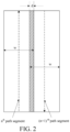
- the work overlap value refers to an overlapped portion between a working width of the autonomous robot working along one of the adjacent path segments and a working width of the autonomous robot working along the other of the adjacent path segments. For example, in FIG.
- an n th path segment is adjacent to an (n+1) th path segment
- a working width of the autonomous robot working along the n th path segment is w
- a working width of the autonomous robot working along the (n+1) th path segment is w
- a work overlap value between the two adjacent path segments is d (for example, as shown by a portion where oblique lines are drawn in FIG. 2 ).
- the autonomous robot may sometimes work in a non-flat working area.
- a work overlap value between adjacent path segments is a default value (for example, ⁇ 1 in FIG. 3 ).
- ⁇ is a slope angle of the slope 2
- cos ⁇ L 1 /L 3
- L 3 is a width between adjacent path segments in an area with the slope 2. Because L 3 >L 2 > L 1 and the working width of the autonomous robot is fixed, ⁇ 3 ⁇ ⁇ 2 ⁇ ⁇ 1 .
- the working width of the autonomous robot is determined by a working execution mechanism of the autonomous robot.
- the autonomous robot is a robotic lawn mower
- the diameter of a cutting deck of the robotic lawn mower is a working width of the robotic lawn mower.
- the work overlap value between adjacent path segments decreases with the increase of the slope angle.
- the slope angle is greater than a particular value (for example, as shown by ⁇ in FIG. 3 )
- the autonomous robot misses a working area, which reduces a work coverage ratio of the autonomous robot in the full-coverage mode.
- a working area of an automatic lawn mower is used as an example.
- An actual lawn usually has uneven terrain such as high slopes due to a special layout of a user's residential environment or garden. If the automatic lawn mower keeps performing coverage cutting based on a full-coverage working path planned based on a two-dimensional map, the autonomous robot is prone to a cutting miss in a high slope scenario.
- the autonomous robot according to some embodiments of this specification is provided with a moving path planning apparatus.
- the moving path planning apparatus can automatically adjust a work overlap value between adjacent path segments during planning of a moving path in a target working area, to keep the work overlap value between the adjacent path segments within an appropriate range. Therefore, the problem that the autonomous robot misses a working area in a high slope scenario can be effectively prevented, and a work coverage ratio of the autonomous robot in a full-coverage mode is therefore improved.
- the automatically adjusting a work overlap value between adjacent path segments may include: automatically adjusting the work overlap value between the adjacent path segments according to environmental information of the autonomous robot.
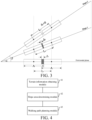
- the moving path planning apparatus may include a terrain information obtaining module 41, a slope area determining module 42, and a moving path planning module 42.
- the terrain information obtaining module 41 may be configured to obtain terrain distribution information of a target working area.
- the slope area determining module 42 may be configured to determine, according to the terrain distribution information, whether a slope area exists in the target working area.
- the moving path planning module 43 may be configured to determine, if a slope area exists in the target working area, a width value between adjacent path segments according to the terrain distribution information during planning of a moving path in the slope area, to keep a work overlap value between the adjacent path segments within a specified range (for example, 1 cm to 5 cm).
- the autonomous robot may determine a width value between adj acent path segments according to the terrain distribution information during planning of a moving path in the slope area, to keep a work overlap value between adjacent path segments within a range not less than zero, thereby effectively preventing the autonomous robot from missing a working area in the high slope scenario.
- a distance from any location point x on the path segment n to the path segment m is a width between the location point x on the path segment n and the path segment m (for example, shown by L 1 , L 2 , and L 3 in FIG. 3 ).
- the work overlap value should not be excessively large (for example, exceeds the value of a default work overlap value), to avoid affecting the working efficiency of the autonomous robot due to a large work overlap value.
- the terrain information obtaining module 41 may allow the autonomous robot to traverse the target working area in advance and invoke an inclination sensor, a gyroscope, or the like provided in the autonomous robot to acquire slope distribution information of the target working area during traversal.
- the traversal may be implemented only to acquire slope distribution information.
- the traversal may be performing a full-coverage work task and at the same time acquiring slope distribution information in the process of performing the work task.
- the autonomous robot may plan the full-coverage working path according to a two-dimensional map (for example, as shown in FIG.
- mapping stage created in a mapping stage (it can be understood that, terrain is not taken into consideration in the planning of the full-coverage working path in this case), to facilitate the traverse of the target working area by the autonomous robot according to the full-coverage working path, thereby acquiring slope distribution information of the target working area.
- the first slope angle value may be used as a boundary to define the flat area and the slope area. That is, in the target working area, an area with a slope angle less than the first slope angle value may be referred to as the flat area, and an area with a slope angle reaching the first slope angle value may be referred to as the slope area.
- the slope distribution information of the target working area may be represented by a uniform slope distribution map of the target working area.
- the slope area determining module 42 may determine whether a slope area exists in the target working area through a uniform slope line on the uniform slope distribution map. For example, in an exemplary embodiment shown in FIG. 6 , assuming that a slope angle of 10° is used as the first slope angle value, the slope area in the target working area may be determined by deleting or concealing contour lines of flat areas with slope angles less than 10° and keeping areas with slope angles not less than 10°.
- the moving path planning module 43 may first partition the target working area. For example, when the slope area is a regular area (that is, the outer contour of the slope area has a regular shape such as a rectangle), the target working area may be directly partitioned by using the outer contour of the slope area as a boundary, to facilitate subsequent moving path planning.
- the moving path planning module 43 may virtually regularize the slope area to make the slope area form a regular working area with a virtual boundary, thereby further facilitating subsequent moving path planning.
- the slope area is an irregular area (that is, the outer contour of the slope area has an irregular shape)
- the moving path planning module 43 may virtually regularize the slope area to make the slope area form a regular working area with a virtual boundary, thereby further facilitating subsequent moving path planning.
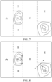
- S 1 and S2 there are two slope areas S 1 and S2 in the target working area. Because both S 1 and S2 are irregular areas, S 1 and S2 may be virtually regularized by, for example, generating the smallest circumscribed rectangles of S 1 and S2 (for example, shown by the thin dot-dashed line in FIG. 7 ).
- the entire target working area may be divided into seven work zones A, B, C, D, E, S1, and S2 based on the virtual boundaries of S1 and S2 and the boundary of the target working area.
- the moving path planning module 43 may separately plan a full-coverage working path for each work zone. Generally, for work zones located in the flat area, during planning of a square wave-shaped path, the moving path planning module 43 may plan each path segment according to a default path segment interval (that is, a width value between adjacent path segments). For work zones located in the slope area, to avoid missing a working area, the moving path planning module 43 may adaptively adjust a width value (for example, adjust L 2 and L 3 in FIG. 3 ) between adjacent path segments according to a slope angle value of each location point on adjacent path segments and the working width of the autonomous robot, to keep the work overlap value between the adjacent path segments within a specified range.
- a width value for example, adjust L 2 and L 3 in FIG. 3
- the adaptive adjustment means that a width value between adjacent path segments is adjusted according to the largest slope angle value (for example, 0°, 20°, 30°) of a slope area having different slopes, so that even at the largest slope angle, the corresponding work overlap value is positive, that is, there is no possibility of missing a working area.
- the largest slope angle value for example, 0°, 20°, 30°
- a square wave-shaped path is used as an example.
- the moving path planning module 43 can plan each path segment according to a default moving direction (for example, a moving direction in the five work zones A, B, C, D, and E in FIG. 9 is the default moving direction).
- a default moving direction for example, a moving direction in the five work zones A, B, C, D, and E in FIG. 9 is the default moving direction.
- the moving path planning module 43 needs to avoid a gradient direction of the slope area as much as possible, making it less difficult for the autonomous robot to climb.
- the moving path planning module 43 may first determine the gradient direction of the slope area (for example, as shown by a solid double-headed arrow in FIG. 8 ); and determine whether a slope angle value corresponding to the gradient direction exceeds a second slope angle value (the second slope angle value may be set based on the climbing limit of the autonomous robot), where the second slope angle value is greater than the first slope angle value. If the slope angle value corresponding to the gradient direction exceeds the second slope angle value, it indicates that the largest slope angle of the slope area may affect the climbing of the autonomous robot. Therefore, during planning of a moving path in the work zones located in the slope area, the moving path planning module 43 may keep an angle between the moving direction of the moving path and the gradient direction within a specified angle range.
- the moving path planning module 43 may make the angle between the moving direction of the moving path and the gradient direction be a specified value.
- the specified value is larger, it is less difficult for the autonomous robot to climb. Therefore, when the specified value is 90° (for example, as shown by dot-dashed double-headed arrow in FIG. 9 ), the difficulty for the autonomous robot to climb can be reduced to the minimum.
- the moving path planning module 43 may use the default moving direction as the moving direction of the moving path.
- the corresponding square wave-shaped path can be drawn (for example, as shown in FIG. 9 ), thereby completing the planning of the full-coverage working path for the target working area while taking the slope information of the target working area into consideration.
- the autonomous robot can subsequently perform each full-coverage work task according to the full-coverage working path.
- the apparatus is divided into units according to functions, which are separately described.
- the functions of the units may be implemented in the same piece of or a plurality of pieces of software and/or hardware.
- a moving path planning method for an autonomous robot of this specification may include: automatically adjusting a work overlap value between adj acent path segments during planning of a moving path in a target working area.
- the automatically adjusting a work overlap value between adjacent path segments may include: automatically adjusting the work overlap value between the adjacent path segments according to environmental information of the autonomous robot.
- the moving path planning method for an autonomous robot may include the following steps:
- the terrain distribution information includes at least one of the following: slope distribution information, absolute height distribution information, relative height difference distribution information, or height change rate distribution information.
- the determining, according to the terrain distribution information, whether a slope area exists in the target working area includes: determining, according to whether a slope angle value of the slope area reaches a first slope angle value, whether a slope area exists in the target working area.
- the determining a width value between adjacent path segments according to the slope distribution information includes: determining the width value between the adjacent path segments according to a slope angle value of each location point on the adjacent path segments and a working width of the autonomous robot.
- the method further includes:
- the keeping an angle between a moving direction of the moving path and the gradient direction within a preset angle range includes: making the angle between the moving direction of the moving path and the gradient direction be a specified value.
- the method further includes: if the slope angle value corresponding to the gradient direction does not exceed the second slope angle value, using a default moving direction as the moving direction of the moving path during planning of the moving path in the slope area.
- the obtaining terrain distribution information of a target working area includes: acquiring the terrain distribution information of the target working area in a process of making the autonomous robot traverse the target working area.
- the terrain distribution information of a target working area includes: a uniform slope distribution map of the target working area.
- These computer program instructions may be stored in a computer-readable memory that can instruct a computer or another programmable data processing device to work in a specific manner, so that the instructions stored in the computer-readable memory generate an artifact that includes an instruction apparatus.
- the instruction apparatus implements a specific function in one or more procedures in the flowcharts and/or in one or more blocks in the block diagrams.
- These computer program instructions may be loaded onto a computer or another programmable data processing device, so that a series of operations and steps are performed on the computer or the another programmable device, thereby generating computer-implemented processing. Therefore, the instructions executed on the computer or the another programmable device provide steps for implementing a specific function in one or more processes in the flowcharts and/or in one or more blocks in the block diagrams.
- a computing device includes one or more processors (CPUs), an input/output (I/O) interface, a network interface, and an internal memory.
- processors CPUs
- I/O input/output
- the memory may include a form such as a volatile memory, a random access memory (RAM), and/or a non-volatile memory such as a read-only memory (ROM) or a flash memory (flash RAM) in a computer-readable medium.
- RAM random access memory
- non-volatile memory such as a read-only memory (ROM) or a flash memory (flash RAM) in a computer-readable medium.
- ROM read-only memory
- flash RAM flash memory
- the computer-readable medium includes a non-volatile medium and a volatile medium, a removable medium and a non-removable medium, which may implement storage of information by using any method or technology.
- the information may be a computer-readable instruction, a data structure, a program module, or other data.
- Examples of a storage medium of a computer include, but are not limited to, a phase change memory (PRAM), a static random access memory (SRAM), a dynamic random access memory (DRAM), or other types of RAMs, a ROM, an erasable programmable read only memory (EEPROM), a flash memory or another storage technology, a compact disc read-only memory (CD-ROM), a digital versatile disc (DVD) or another optical storage, or a cartridge tape.
- PRAM phase change memory
- SRAM static random access memory
- DRAM dynamic random access memory
- RAM random access memory
- EEPROM erasable programmable read only memory
- CD-ROM compact disc read-only memory
- DVD digital versatile disc
- a magnetic storage of a magnetic disk or a disc, another magnetic storage device, or any other non-transmission medium may be configured to store information that can be accessed by a computing device.
- the computer-readable medium does not include transitory computer-readable media (transitory media), such as a modulated data signal and a carrier.
- this specification may be provided as a method, a system, or a computer program product. Therefore, this specification may use a form of hardware only embodiments, software only embodiments, or embodiments with a combination of software and hardware. Moreover, this specification may use a form of a computer program product that is implemented on one or more computer-usable storage media (including but not limited to a disk memory, a CD-ROM, an optical memory, and the like) that include computer-usable program code.
- computer-usable storage media including but not limited to a disk memory, a CD-ROM, an optical memory, and the like
- the program module includes a routine, a program, an object, a component, a data structure, and the like for executing a particular task or implementing a particular abstract data type.
- This specification may be implemented in a distributed computing environment in which tasks are performed by remote processing devices connected by using a communication network.
- the program module may be located in both local and remote computer storage media including storage devices.
Landscapes
- Engineering & Computer Science (AREA)
- Radar, Positioning & Navigation (AREA)
- Automation & Control Theory (AREA)
- Remote Sensing (AREA)
- Physics & Mathematics (AREA)
- General Physics & Mathematics (AREA)
- Aviation & Aerospace Engineering (AREA)
- Business, Economics & Management (AREA)
- Health & Medical Sciences (AREA)
- Artificial Intelligence (AREA)
- Evolutionary Computation (AREA)
- Game Theory and Decision Science (AREA)
- Medical Informatics (AREA)
- Control Of Position, Course, Altitude, Or Attitude Of Moving Bodies (AREA)
- Manipulator (AREA)
Claims (13)
- Gehpfadplanungsverfahren für einen autonomen Roboter, das Folgendes umfasst:Erhalten (101) von Neigungsverteilungsinformationen zu einem Zielarbeitsbereich undBestimmen (102) gemäß den Neigungsverteilungsinformationen, ob im Zielarbeitsbereich ein Neigungsbereich existiert; gekennzeichnet durchBestimmen (103) eines Breitenwertes zwischen benachbarten Pfadsegmenten gemäß den Neigungsverteilungsinformationen während einer Planung eines Gehpfades im Neigungsbereich, wenn im Zielarbeitsbereich ein Neigungsbereich existiert, um ein Arbeitsüberlappungsverhältnis zwischen benachbarten Pfadsegmenten in einer spezifizierten Spanne zu halten.
- Bewegungspfadplanungsverfahren nach Anspruch 1, das das Planen eines alles abdeckenden Arbeitspfades umfasst, der auf Basis einer zweidimensionalen Karte geplant wird.
- Bewegungspfadplanungsverfahren für einen autonomen Roboter nach Anspruch 1, wobei, wenn die Neigung größer als oder gleich 10° ist, der Arbeitsüberlappungswert zwischen den benachbarten Pfadsegmenten größer als oder gleich 1 cm und kleiner als oder gleich 5 cm ist.
- Gehpfadplanungsverfahren für einen autonomen Roboter nach Anspruch 1, wobei das Bestimmen gemäß den Neigungsverteilungsinformationen, ob im Zielarbeitsbereich ein Neigungsbereich existiert, Folgendes umfasst:
Bestimmen gemäß dem, ob ein Neigungswinkelwert des Zielarbeitsbereichs einen ersten Neigungswinkelwert erreicht, ob im Zielarbeitsbereich ein Neigungsbereich existiert. - Gehpfadplanungsverfahren für einen autonomen Roboter nach Anspruch 4, wobei das Bestimmen eines Breitenwertes zwischen benachbarten Pfadsegmenten gemäß den Neigungsverteilungsinformationen Folgendes umfasst:
Bestimmen des Breitenwertes zwischen den benachbarten Pfadsegmenten gemäß einem Neigungswinkelwert von jeder Stelle auf den benachbarten Pfadsegmenten und einer Arbeitsbreite des autonomen Roboters. - Gehpfadplanungsverfahren für einen autonomen Roboter nach Anspruch 4, wobei das Verfahren ferner Folgendes umfasst:Bestimmen einer Gradientenrichtung des Neigungsbereichs, wenn ein Neigungsbereich im Zielarbeitsbereich existiert;Bestimmen, ob ein Neigungswinkelwert, der der Gradientenrichtung entspricht, einen zweiten Neigungswinkelwert überschreitet, wobei der zweite Neigungswinkelwert größer ist als der erste Neigungswinkelwert; undwenn der Neigungswinkelwert, der der Gradientenrichtung entspricht, den zweiten Neigungswinkelwert überschreitet, Beibehalten eines Winkels zwischen einer Gehrichtung des Gehpfades und der Gradientenrichtung im Neigungsbereich in einer spezifizierten Winkelspanne während einer Planung des Gehpfades.
- Gehpfadplanungsverfahren für einen autonomen Roboter nach Anspruch 6, wobei das Beibehalten eines Winkels zwischen einer Gehrichtung des Gehpfades und der Gradientenrichtung in einer voreingestellten Winkelspanne Folgendes umfasst:
Festlegen des Winkels zwischen der Gehrichtung des Gehpfades und der Gradientenrichtung auf einen spezifizierten Wert. - Gehpfadplanungsverfahren für einen autonomen Roboter nach Anspruch 6, wobei das Verfahren ferner Folgendes umfasst:
wenn der Neigungswinkelwert, der der Gradientenrichtung entspricht, den zweiten Neigungswinkelwert nicht überschreitet, Verwenden einer standardmäßigen Gehrichtung als die Gehrichtung des Gehpfades während einer Planung des Gehpfades im Neigungsbereich. - Gehpfadplanungsverfahren für einen autonomen Roboter nach Anspruch 1, wobei das Erhalten von Neigungsverteilungsinformationen eines Zielarbeitsbereichs Folgendes umfasst:
Erfassen der Neigungsverteilungsinformationen des Zielarbeitsbereichs in einem Prozess des Veranlassens des autonomen Roboters, den Zielarbeitsbereich zu durchqueren. - Gehpfadplanungsverfahren für einen autonomen Roboter nach Anspruch 1, wobei die Neigungsverteilungsinformationen des Zielarbeitsbereichs Folgendes umfassen:
eine einheitliche Neigungsverteilungskarte des Zielarbeitsbereichs. - Gehpfadplanungsvorrichtung für einen autonomen Roboter, die Folgendes umfasst:ein Neigungsinformationserhaltungsmodul, das dazu ausgelegt ist, Neigungsverteilungsinformationen zu einem Zielarbeitsbereich zu erhalten; undein Neigungsbereichsbestimmungsmodul, das dazu ausgelegt ist, gemäß den Neigungsverteilungsinformationen zu bestimmen, ob im Zielarbeitsbereich ein Neigungsbereich existiert; gekennzeichnet durchein Gehpfadplanungsmodul, das dazu ausgelegt ist, einen Breitenwert zwischen benachbarten Pfadsegmenten gemäß den Neigungsverteilungsinformationen während einer Planung eines Gehpfads im Neigungsbereich zu bestimmen, wenn im Zielarbeitsbereich ein Neigungsbereich existiert, um ein Arbeitsüberlappungsverhältnis zwischen benachbarten Pfadsegmenten in einer spezifizierten Spanne zu halten.
- Autonomer Roboter, der die Gehpfadplanungsvorrichtung nach Anspruch 11 umfasst.
- Computerspeichermedium, auf dem ein Computerprogramm gespeichert ist, wobei das Computerprogramm, wenn es von einem Prozessor ausgeführt wird, das Gehpfadplanungsverfahren nach einem der Ansprüche 1 bis 10 implementiert.
Applications Claiming Priority (2)
| Application Number | Priority Date | Filing Date | Title |
|---|---|---|---|
| CN201910924785.4A CN112578777A (zh) | 2019-09-27 | 2019-09-27 | 自主机器人及其行走路径规划方法、装置和存储介质 |
| PCT/CN2020/117800 WO2021057909A1 (zh) | 2019-09-27 | 2020-09-25 | 自主机器人及其行走路径规划方法、装置和存储介质 |
Publications (3)
| Publication Number | Publication Date |
|---|---|
| EP4036679A1 EP4036679A1 (de) | 2022-08-03 |
| EP4036679A4 EP4036679A4 (de) | 2023-08-30 |
| EP4036679B1 true EP4036679B1 (de) | 2024-09-04 |
Family
ID=75109873
Family Applications (1)
| Application Number | Title | Priority Date | Filing Date |
|---|---|---|---|
| EP20867377.2A Active EP4036679B1 (de) | 2019-09-27 | 2020-09-25 | Autonomer roboter, fahrtstreckenplanungsverfahren und vorrichtung dafür sowie speichermedium |
Country Status (4)
| Country | Link |
|---|---|
| US (1) | US12235649B2 (de) |
| EP (1) | EP4036679B1 (de) |
| CN (1) | CN112578777A (de) |
| WO (2) | WO2021056789A1 (de) |
Families Citing this family (12)
| Publication number | Priority date | Publication date | Assignee | Title |
|---|---|---|---|---|
| SE547658C2 (en) * | 2020-12-11 | 2025-11-04 | Husqvarna Ab | Robotic lawnmower system and method for provision of map and selection of robotic work tools in a robotic lawnmower system |
| CN113221856B (zh) * | 2021-06-11 | 2022-12-27 | 石家庄铁道大学 | 人群拥挤危险度检测方法、装置及设备 |
| CN115718482A (zh) * | 2021-08-24 | 2023-02-28 | 科沃斯机器人股份有限公司 | 路径规划方法、机器人及存储介质 |
| CN113534823B (zh) * | 2021-09-16 | 2021-12-14 | 季华实验室 | 种植机器人路径规划方法、装置、电子设备和存储介质 |
| CN114442616A (zh) * | 2022-01-05 | 2022-05-06 | 中联重科土方机械有限公司 | 用于挖掘机的控制方法、装置、处理器及挖掘机 |
| CN115032995B (zh) | 2022-06-17 | 2023-07-14 | 未岚大陆(北京)科技有限公司 | 运动控制方法、装置、电子设备及计算机存储介质 |
| CN115291605A (zh) * | 2022-07-22 | 2022-11-04 | 松灵机器人(深圳)有限公司 | 路径规划方法、装置、割草机器人以及存储介质 |
| CN115033110B (zh) * | 2022-08-09 | 2022-10-25 | 环球数科集团有限公司 | 一种虚拟人步态模拟与三维场景路径规划系统 |
| CN115729237B (zh) * | 2022-11-04 | 2026-04-21 | 深圳市正浩创新科技股份有限公司 | 路径规划方法、路径规划装置、自移动设备以及存储介质 |
| CN116465407A (zh) * | 2023-03-21 | 2023-07-21 | 深圳市正浩创新科技股份有限公司 | 路径规划方法、装置、自移动设备及存储介质 |
| CN119803443B (zh) * | 2025-01-15 | 2026-02-17 | 深圳库犸科技有限公司 | 一种地图创建方法、系统、介质、设备和程序产品 |
| CN119688292B (zh) * | 2025-02-24 | 2025-04-22 | 国网山西省电力公司超高压输电分公司 | 一种在线监测输电杆塔螺栓松动用检测装置 |
Family Cites Families (36)
| Publication number | Priority date | Publication date | Assignee | Title |
|---|---|---|---|---|
| US6837033B2 (en) * | 2002-05-23 | 2005-01-04 | Deere & Company | Agricultural bi-mower with cantilever beam suspension |
| US6907336B2 (en) * | 2003-03-31 | 2005-06-14 | Deere & Company | Method and system for efficiently traversing an area with a work vehicle |
| CA2590382C (en) * | 2007-05-28 | 2012-11-13 | Stanley J. Boyko | Castering wheel assembly for rotary mowers |
| CN201178584Y (zh) * | 2008-04-10 | 2009-01-14 | 河南农业大学 | 单牵引斜坡专用割草机 |
| DE102011082416A1 (de) * | 2011-09-09 | 2013-03-14 | Robert Bosch Gmbh | Autonomes Arbeitsgerät |
| US10149430B2 (en) | 2013-02-20 | 2018-12-11 | Husqvarna Ab | Robotic work tool configured for improved turning in a slope, a robotic work tool system, and a method for use in the robot work tool |
| CN103125202B (zh) * | 2013-03-15 | 2016-03-30 | 中国农业大学 | 一种旋转式割草机的刈割方式及装置 |
| JP5336672B1 (ja) * | 2013-04-24 | 2013-11-06 | 有限会社渥美不動産アンドコーポレーション | 自走式草刈り機 |
| KR20210082559A (ko) * | 2014-02-06 | 2021-07-05 | 얀마 파워 테크놀로지 가부시키가이샤 | 병주 작업 시스템 |
| DE102014113965A1 (de) * | 2014-09-26 | 2016-03-31 | Claas Selbstfahrende Erntemaschinen Gmbh | Mähdrescher mit Fahrerassistenzsystem |
| JP6571567B2 (ja) * | 2016-03-18 | 2019-09-04 | ヤンマー株式会社 | 作業車両用経路生成システム |
| KR20200045004A (ko) * | 2016-03-30 | 2020-04-29 | 얀마 가부시키가이샤 | 경로 생성 장치 및 작업차 |
| CN107402570A (zh) | 2016-05-19 | 2017-11-28 | 科沃斯机器人股份有限公司 | 自移动机器人、其控制方法及其组合机器人 |
| EP3459334B1 (de) * | 2016-05-19 | 2022-09-07 | Positec Power Tools (Suzhou) Co., Ltd. | Selbstbewegende vorrichtung und steuerungsverfahren dafür |
| CN107643750B (zh) * | 2016-07-21 | 2020-05-22 | 苏州宝时得电动工具有限公司 | 智能行走设备斜坡的识别方法及其智能行走设备 |
| CN106239507A (zh) | 2016-08-16 | 2016-12-21 | 成都市和平科技有限责任公司 | 一种自动寻路机器人系统及方法 |
| CN106760261B (zh) * | 2016-11-25 | 2022-11-11 | 美建建筑系统(中国)有限公司 | 屋面扫雪机器人 |
| KR102700830B1 (ko) * | 2016-12-26 | 2024-09-02 | 삼성전자주식회사 | 무인 이동체를 제어하기 위한 방법 및 전자 장치 |
| CN108958066A (zh) | 2017-05-19 | 2018-12-07 | 百度在线网络技术(北京)有限公司 | 仿真测试方法和装置 |
| CN109425352A (zh) * | 2017-08-25 | 2019-03-05 | 科沃斯机器人股份有限公司 | 自移动机器人路径规划方法 |
| CN107509443B (zh) * | 2017-09-05 | 2020-01-17 | 惠州市蓝微电子有限公司 | 一种智能割草机的坡地行驶控制方法及系统 |
| WO2019084767A1 (zh) * | 2017-10-31 | 2019-05-09 | 深圳市大疆创新科技有限公司 | 可移动设备作业控制方法及装置、路径规划方法及装置 |
| EP3698618B1 (de) * | 2017-11-16 | 2022-01-05 | Nanjing Chervon Industry Co., Ltd. | Intelligentes rasenmähersystem |
| CN108113583B (zh) * | 2017-12-30 | 2020-07-14 | 珠海市一微半导体有限公司 | 清洁机器人的清洁方法和系统 |
| CN110093955A (zh) * | 2018-01-30 | 2019-08-06 | 岭东核电有限公司 | 用于隧洞的清理收集系统及其控制方法 |
| KR102106100B1 (ko) | 2018-02-02 | 2020-05-06 | 엘지전자 주식회사 | 이동 로봇 |
| CN108732590A (zh) | 2018-05-16 | 2018-11-02 | 重庆邮电大学 | 一种双足机器人及一种斜坡角度测量方法 |
| CN108981726A (zh) | 2018-06-09 | 2018-12-11 | 安徽宇锋智能科技有限公司 | 基于感知定位监测的无人车语义地图建模及构建应用方法 |
| RU2758225C1 (ru) * | 2018-06-29 | 2021-10-26 | Ниссан Мотор Ко., Лтд. | Способ помощи при движении и устройство помощи при движении |
| CN109006783A (zh) * | 2018-08-01 | 2018-12-18 | 牛贞伟 | 一种拔草装置、农田智能拔草机器人 |
| CN109041755A (zh) * | 2018-09-27 | 2018-12-21 | 山东拜罗智能科技有限公司 | 一种陡坡智能割草机器人及控制方法 |
| CN208953962U (zh) | 2018-12-05 | 2019-06-07 | 苏州博众机器人有限公司 | 一种机器人感知系统及机器人 |
| CN109634285B (zh) * | 2019-01-14 | 2022-03-11 | 傲基科技股份有限公司 | 割草机器人及其控制方法 |
| CN109834711B (zh) | 2019-02-21 | 2021-01-12 | 山东职业学院 | 一种四足机器人运动控制方法、系统及机器人 |
| CN109729814A (zh) * | 2019-02-26 | 2019-05-10 | 北斗万春(重庆)智能机器人研究院有限公司 | 刀盘上下自适应调节装置及智能割草机 |
| CN110132215B (zh) * | 2019-04-29 | 2021-08-10 | 丰疆智能科技研究院(常州)有限公司 | 农机作业幅宽自动获取方法和农机作业面积获取方法 |
-
2019
- 2019-09-27 CN CN201910924785.4A patent/CN112578777A/zh active Pending
- 2019-11-22 WO PCT/CN2019/120181 patent/WO2021056789A1/zh not_active Ceased
-
2020
- 2020-09-25 EP EP20867377.2A patent/EP4036679B1/de active Active
- 2020-09-25 WO PCT/CN2020/117800 patent/WO2021057909A1/zh not_active Ceased
- 2020-09-25 US US17/764,138 patent/US12235649B2/en active Active
Also Published As
| Publication number | Publication date |
|---|---|
| EP4036679A4 (de) | 2023-08-30 |
| WO2021056789A1 (zh) | 2021-04-01 |
| US20220390953A1 (en) | 2022-12-08 |
| EP4036679A1 (de) | 2022-08-03 |
| US12235649B2 (en) | 2025-02-25 |
| CN112578777A (zh) | 2021-03-30 |
| WO2021057909A1 (zh) | 2021-04-01 |
Similar Documents
| Publication | Publication Date | Title |
|---|---|---|
| EP4036679B1 (de) | Autonomer roboter, fahrtstreckenplanungsverfahren und vorrichtung dafür sowie speichermedium | |
| US20230320265A1 (en) | System and method for operating an autonomous robotic working machine within a travelling containment zone | |
| CN112230644B (zh) | 自主机器人及其沿边控制方法、装置及存储介质 | |
| EP3529557B1 (de) | Landkartierungs- und -führungssystem | |
| US10197407B2 (en) | Method and robot system for autonomous control of a vehicle | |
| CN109634276B (zh) | 农用车辆无人驾驶控制方法、系统及该农用车辆 | |
| CN112306049B (zh) | 自主机器人及其避障方法、装置和存储介质 | |
| US20190208695A1 (en) | Path Planning for Area Coverage | |
| EP3330824A1 (de) | Verfahren und robotersystem für unabhängige fahrzeugsteuerung | |
| CN109845475B (zh) | 智能割草机器人的调头控制方法及系统 | |
| CN108398944A (zh) | 自移动设备的作业方法、自移动设备、存储器和服务器 | |
| US12332650B2 (en) | Traversal method and system, robot, and readable storage medium | |
| SE544259C2 (en) | Robotic work tool system and method for defining a working area | |
| CN113352325A (zh) | 养殖舱自动清洗方法及设备 | |
| CN114600622A (zh) | 行进路径规划方法、控制装置、割草机、自移动系统 | |
| CN112306050A (zh) | 自主机器人及其行走路径规划方法、装置和存储介质 | |
| CN113064408A (zh) | 自主机器人及其控制方法、计算机存储介质 | |
| WO2023217231A1 (zh) | 作业边界生成方法、作业控制方法、设备及存储介质 | |
| CN115562287A (zh) | 自移动设备的航向校正方法、装置和自移动设备 | |
| WO2022116935A1 (zh) | 路径范围确定方法及装置、路径规划方法及装置 | |
| CN112743534B (zh) | 自主机器人及其移动控制方法、装置和存储介质 | |
| CN118329043A (zh) | 农机全覆盖路径规划收边方法、系统、农机、设备和介质 | |
| EP3696640B1 (de) | Robotisches fahrzeug für beweglichen betrieb in einem arbeitsbereich | |
| CN111190209A (zh) | 一种割草机平行切割的方法、装置及割草机 | |
| CN120779975B (zh) | 一种全流程动态避障的农机路径规划方法 |
Legal Events
| Date | Code | Title | Description |
|---|---|---|---|
| STAA | Information on the status of an ep patent application or granted ep patent |
Free format text: STATUS: THE INTERNATIONAL PUBLICATION HAS BEEN MADE |
|
| PUAI | Public reference made under article 153(3) epc to a published international application that has entered the european phase |
Free format text: ORIGINAL CODE: 0009012 |
|
| STAA | Information on the status of an ep patent application or granted ep patent |
Free format text: STATUS: REQUEST FOR EXAMINATION WAS MADE |
|
| 17P | Request for examination filed |
Effective date: 20220331 |
|
| AK | Designated contracting states |
Kind code of ref document: A1 Designated state(s): AL AT BE BG CH CY CZ DE DK EE ES FI FR GB GR HR HU IE IS IT LI LT LU LV MC MK MT NL NO PL PT RO RS SE SI SK SM TR |
|
| DAV | Request for validation of the european patent (deleted) | ||
| DAX | Request for extension of the european patent (deleted) | ||
| A4 | Supplementary search report drawn up and despatched |
Effective date: 20230801 |
|
| RIC1 | Information provided on ipc code assigned before grant |
Ipc: B25J 9/16 20060101ALI20230726BHEP Ipc: G05D 1/02 20200101AFI20230726BHEP |
|
| REG | Reference to a national code |
Ref country code: DE Free format text: PREVIOUS MAIN CLASS: G05D0001020000 Ref country code: DE Ref legal event code: R079 Ref document number: 602020037299 Country of ref document: DE Free format text: PREVIOUS MAIN CLASS: G05D0001020000 Ipc: G05D0001000000 |
|
| P01 | Opt-out of the competence of the unified patent court (upc) registered |
Effective date: 20240312 |
|
| GRAP | Despatch of communication of intention to grant a patent |
Free format text: ORIGINAL CODE: EPIDOSNIGR1 |
|
| STAA | Information on the status of an ep patent application or granted ep patent |
Free format text: STATUS: GRANT OF PATENT IS INTENDED |
|
| RIC1 | Information provided on ipc code assigned before grant |
Ipc: G05D 1/00 20060101AFI20240322BHEP |
|
| INTG | Intention to grant announced |
Effective date: 20240426 |
|
| GRAS | Grant fee paid |
Free format text: ORIGINAL CODE: EPIDOSNIGR3 |
|
| GRAA | (expected) grant |
Free format text: ORIGINAL CODE: 0009210 |
|
| STAA | Information on the status of an ep patent application or granted ep patent |
Free format text: STATUS: THE PATENT HAS BEEN GRANTED |
|
| AK | Designated contracting states |
Kind code of ref document: B1 Designated state(s): AL AT BE BG CH CY CZ DE DK EE ES FI FR GB GR HR HU IE IS IT LI LT LU LV MC MK MT NL NO PL PT RO RS SE SI SK SM TR |
|
| REG | Reference to a national code |
Ref country code: GB Ref legal event code: FG4D |
|
| REG | Reference to a national code |
Ref country code: CH Ref legal event code: EP |
|
| REG | Reference to a national code |
Ref country code: IE Ref legal event code: FG4D |
|
| REG | Reference to a national code |
Ref country code: DE Ref legal event code: R096 Ref document number: 602020037299 Country of ref document: DE |
|
| REG | Reference to a national code |
Ref country code: SE Ref legal event code: TRGR |
|
| REG | Reference to a national code |
Ref country code: LT Ref legal event code: MG9D |
|
| REG | Reference to a national code |
Ref country code: NL Ref legal event code: MP Effective date: 20240904 |
|
| PG25 | Lapsed in a contracting state [announced via postgrant information from national office to epo] |
Ref country code: NO Free format text: LAPSE BECAUSE OF FAILURE TO SUBMIT A TRANSLATION OF THE DESCRIPTION OR TO PAY THE FEE WITHIN THE PRESCRIBED TIME-LIMIT Effective date: 20241204 |
|
| PG25 | Lapsed in a contracting state [announced via postgrant information from national office to epo] |
Ref country code: GR Free format text: LAPSE BECAUSE OF FAILURE TO SUBMIT A TRANSLATION OF THE DESCRIPTION OR TO PAY THE FEE WITHIN THE PRESCRIBED TIME-LIMIT Effective date: 20241205 Ref country code: PL Free format text: LAPSE BECAUSE OF FAILURE TO SUBMIT A TRANSLATION OF THE DESCRIPTION OR TO PAY THE FEE WITHIN THE PRESCRIBED TIME-LIMIT Effective date: 20240904 Ref country code: FI Free format text: LAPSE BECAUSE OF FAILURE TO SUBMIT A TRANSLATION OF THE DESCRIPTION OR TO PAY THE FEE WITHIN THE PRESCRIBED TIME-LIMIT Effective date: 20240904 |
|
| PG25 | Lapsed in a contracting state [announced via postgrant information from national office to epo] |
Ref country code: BG Free format text: LAPSE BECAUSE OF FAILURE TO SUBMIT A TRANSLATION OF THE DESCRIPTION OR TO PAY THE FEE WITHIN THE PRESCRIBED TIME-LIMIT Effective date: 20240904 |
|
| PG25 | Lapsed in a contracting state [announced via postgrant information from national office to epo] |
Ref country code: LV Free format text: LAPSE BECAUSE OF FAILURE TO SUBMIT A TRANSLATION OF THE DESCRIPTION OR TO PAY THE FEE WITHIN THE PRESCRIBED TIME-LIMIT Effective date: 20240904 |
|
| PG25 | Lapsed in a contracting state [announced via postgrant information from national office to epo] |
Ref country code: HR Free format text: LAPSE BECAUSE OF FAILURE TO SUBMIT A TRANSLATION OF THE DESCRIPTION OR TO PAY THE FEE WITHIN THE PRESCRIBED TIME-LIMIT Effective date: 20240904 |
|
| PG25 | Lapsed in a contracting state [announced via postgrant information from national office to epo] |
Ref country code: ES Free format text: LAPSE BECAUSE OF FAILURE TO SUBMIT A TRANSLATION OF THE DESCRIPTION OR TO PAY THE FEE WITHIN THE PRESCRIBED TIME-LIMIT Effective date: 20240904 Ref country code: RS Free format text: LAPSE BECAUSE OF FAILURE TO SUBMIT A TRANSLATION OF THE DESCRIPTION OR TO PAY THE FEE WITHIN THE PRESCRIBED TIME-LIMIT Effective date: 20241204 |
|
| PG25 | Lapsed in a contracting state [announced via postgrant information from national office to epo] |
Ref country code: RS Free format text: LAPSE BECAUSE OF FAILURE TO SUBMIT A TRANSLATION OF THE DESCRIPTION OR TO PAY THE FEE WITHIN THE PRESCRIBED TIME-LIMIT Effective date: 20241204 Ref country code: PL Free format text: LAPSE BECAUSE OF FAILURE TO SUBMIT A TRANSLATION OF THE DESCRIPTION OR TO PAY THE FEE WITHIN THE PRESCRIBED TIME-LIMIT Effective date: 20240904 Ref country code: NO Free format text: LAPSE BECAUSE OF FAILURE TO SUBMIT A TRANSLATION OF THE DESCRIPTION OR TO PAY THE FEE WITHIN THE PRESCRIBED TIME-LIMIT Effective date: 20241204 Ref country code: LV Free format text: LAPSE BECAUSE OF FAILURE TO SUBMIT A TRANSLATION OF THE DESCRIPTION OR TO PAY THE FEE WITHIN THE PRESCRIBED TIME-LIMIT Effective date: 20240904 Ref country code: HR Free format text: LAPSE BECAUSE OF FAILURE TO SUBMIT A TRANSLATION OF THE DESCRIPTION OR TO PAY THE FEE WITHIN THE PRESCRIBED TIME-LIMIT Effective date: 20240904 Ref country code: GR Free format text: LAPSE BECAUSE OF FAILURE TO SUBMIT A TRANSLATION OF THE DESCRIPTION OR TO PAY THE FEE WITHIN THE PRESCRIBED TIME-LIMIT Effective date: 20241205 Ref country code: FI Free format text: LAPSE BECAUSE OF FAILURE TO SUBMIT A TRANSLATION OF THE DESCRIPTION OR TO PAY THE FEE WITHIN THE PRESCRIBED TIME-LIMIT Effective date: 20240904 Ref country code: ES Free format text: LAPSE BECAUSE OF FAILURE TO SUBMIT A TRANSLATION OF THE DESCRIPTION OR TO PAY THE FEE WITHIN THE PRESCRIBED TIME-LIMIT Effective date: 20240904 Ref country code: BG Free format text: LAPSE BECAUSE OF FAILURE TO SUBMIT A TRANSLATION OF THE DESCRIPTION OR TO PAY THE FEE WITHIN THE PRESCRIBED TIME-LIMIT Effective date: 20240904 |
|
| REG | Reference to a national code |
Ref country code: AT Ref legal event code: MK05 Ref document number: 1721037 Country of ref document: AT Kind code of ref document: T Effective date: 20240904 |
|
| PG25 | Lapsed in a contracting state [announced via postgrant information from national office to epo] |
Ref country code: NL Free format text: LAPSE BECAUSE OF FAILURE TO SUBMIT A TRANSLATION OF THE DESCRIPTION OR TO PAY THE FEE WITHIN THE PRESCRIBED TIME-LIMIT Effective date: 20240904 |
|
| PG25 | Lapsed in a contracting state [announced via postgrant information from national office to epo] |
Ref country code: PT Free format text: LAPSE BECAUSE OF FAILURE TO SUBMIT A TRANSLATION OF THE DESCRIPTION OR TO PAY THE FEE WITHIN THE PRESCRIBED TIME-LIMIT Effective date: 20250106 Ref country code: IS Free format text: LAPSE BECAUSE OF FAILURE TO SUBMIT A TRANSLATION OF THE DESCRIPTION OR TO PAY THE FEE WITHIN THE PRESCRIBED TIME-LIMIT Effective date: 20250104 |
|
| PG25 | Lapsed in a contracting state [announced via postgrant information from national office to epo] |
Ref country code: SM Free format text: LAPSE BECAUSE OF FAILURE TO SUBMIT A TRANSLATION OF THE DESCRIPTION OR TO PAY THE FEE WITHIN THE PRESCRIBED TIME-LIMIT Effective date: 20240904 Ref country code: RO Free format text: LAPSE BECAUSE OF FAILURE TO SUBMIT A TRANSLATION OF THE DESCRIPTION OR TO PAY THE FEE WITHIN THE PRESCRIBED TIME-LIMIT Effective date: 20240904 |
|
| PG25 | Lapsed in a contracting state [announced via postgrant information from national office to epo] |
Ref country code: EE Free format text: LAPSE BECAUSE OF FAILURE TO SUBMIT A TRANSLATION OF THE DESCRIPTION OR TO PAY THE FEE WITHIN THE PRESCRIBED TIME-LIMIT Effective date: 20240904 Ref country code: AT Free format text: LAPSE BECAUSE OF FAILURE TO SUBMIT A TRANSLATION OF THE DESCRIPTION OR TO PAY THE FEE WITHIN THE PRESCRIBED TIME-LIMIT Effective date: 20240904 |
|
| PG25 | Lapsed in a contracting state [announced via postgrant information from national office to epo] |
Ref country code: CZ Free format text: LAPSE BECAUSE OF FAILURE TO SUBMIT A TRANSLATION OF THE DESCRIPTION OR TO PAY THE FEE WITHIN THE PRESCRIBED TIME-LIMIT Effective date: 20240904 |
|
| PG25 | Lapsed in a contracting state [announced via postgrant information from national office to epo] |
Ref country code: IT Free format text: LAPSE BECAUSE OF FAILURE TO SUBMIT A TRANSLATION OF THE DESCRIPTION OR TO PAY THE FEE WITHIN THE PRESCRIBED TIME-LIMIT Effective date: 20240904 Ref country code: SK Free format text: LAPSE BECAUSE OF FAILURE TO SUBMIT A TRANSLATION OF THE DESCRIPTION OR TO PAY THE FEE WITHIN THE PRESCRIBED TIME-LIMIT Effective date: 20240904 |
|
| REG | Reference to a national code |
Ref country code: CH Ref legal event code: PL |
|
| PG25 | Lapsed in a contracting state [announced via postgrant information from national office to epo] |
Ref country code: LU Free format text: LAPSE BECAUSE OF NON-PAYMENT OF DUE FEES Effective date: 20240925 |
|
| REG | Reference to a national code |
Ref country code: DE Ref legal event code: R097 Ref document number: 602020037299 Country of ref document: DE |
|
| PG25 | Lapsed in a contracting state [announced via postgrant information from national office to epo] |
Ref country code: MC Free format text: LAPSE BECAUSE OF FAILURE TO SUBMIT A TRANSLATION OF THE DESCRIPTION OR TO PAY THE FEE WITHIN THE PRESCRIBED TIME-LIMIT Effective date: 20240904 |
|
| PG25 | Lapsed in a contracting state [announced via postgrant information from national office to epo] |
Ref country code: DK Free format text: LAPSE BECAUSE OF FAILURE TO SUBMIT A TRANSLATION OF THE DESCRIPTION OR TO PAY THE FEE WITHIN THE PRESCRIBED TIME-LIMIT Effective date: 20240904 |
|
| REG | Reference to a national code |
Ref country code: BE Ref legal event code: MM Effective date: 20240930 |
|
| PLBE | No opposition filed within time limit |
Free format text: ORIGINAL CODE: 0009261 |
|
| STAA | Information on the status of an ep patent application or granted ep patent |
Free format text: STATUS: NO OPPOSITION FILED WITHIN TIME LIMIT |
|
| PG25 | Lapsed in a contracting state [announced via postgrant information from national office to epo] |
Ref country code: BE Free format text: LAPSE BECAUSE OF NON-PAYMENT OF DUE FEES Effective date: 20240930 |
|
| PG25 | Lapsed in a contracting state [announced via postgrant information from national office to epo] |
Ref country code: CH Free format text: LAPSE BECAUSE OF NON-PAYMENT OF DUE FEES Effective date: 20240930 |
|
| PG25 | Lapsed in a contracting state [announced via postgrant information from national office to epo] |
Ref country code: IE Free format text: LAPSE BECAUSE OF NON-PAYMENT OF DUE FEES Effective date: 20240925 |
|
| 26N | No opposition filed |
Effective date: 20250605 |
|
| PGFP | Annual fee paid to national office [announced via postgrant information from national office to epo] |
Ref country code: DE Payment date: 20250916 Year of fee payment: 6 |
|
| PGFP | Annual fee paid to national office [announced via postgrant information from national office to epo] |
Ref country code: GB Payment date: 20250919 Year of fee payment: 6 |
|
| PGFP | Annual fee paid to national office [announced via postgrant information from national office to epo] |
Ref country code: FR Payment date: 20250929 Year of fee payment: 6 |
|
| PGFP | Annual fee paid to national office [announced via postgrant information from national office to epo] |
Ref country code: SE Payment date: 20250925 Year of fee payment: 6 |
|
| PG25 | Lapsed in a contracting state [announced via postgrant information from national office to epo] |
Ref country code: CY Free format text: LAPSE BECAUSE OF FAILURE TO SUBMIT A TRANSLATION OF THE DESCRIPTION OR TO PAY THE FEE WITHIN THE PRESCRIBED TIME-LIMIT; INVALID AB INITIO Effective date: 20200925 |
|
| PG25 | Lapsed in a contracting state [announced via postgrant information from national office to epo] |
Ref country code: HU Free format text: LAPSE BECAUSE OF FAILURE TO SUBMIT A TRANSLATION OF THE DESCRIPTION OR TO PAY THE FEE WITHIN THE PRESCRIBED TIME-LIMIT; INVALID AB INITIO Effective date: 20200925 |