EP4036661B1 - Am körper tragbare vorrichtung und anzeigeverfahren - Google Patents
Am körper tragbare vorrichtung und anzeigeverfahren Download PDFInfo
- Publication number
- EP4036661B1 EP4036661B1 EP20869456.2A EP20869456A EP4036661B1 EP 4036661 B1 EP4036661 B1 EP 4036661B1 EP 20869456 A EP20869456 A EP 20869456A EP 4036661 B1 EP4036661 B1 EP 4036661B1
- Authority
- EP
- European Patent Office
- Prior art keywords
- dial plate
- watch body
- wearable device
- annular
- display
- Prior art date
- Legal status (The legal status is an assumption and is not a legal conclusion. Google has not performed a legal analysis and makes no representation as to the accuracy of the status listed.)
- Active
Links
Images





Classifications
-
- G—PHYSICS
- G01—MEASURING; TESTING
- G01D—MEASURING NOT SPECIALLY ADAPTED FOR A SPECIFIC VARIABLE; ARRANGEMENTS FOR MEASURING TWO OR MORE VARIABLES NOT COVERED IN A SINGLE OTHER SUBCLASS; TARIFF METERING APPARATUS; MEASURING OR TESTING NOT OTHERWISE PROVIDED FOR
- G01D5/00—Mechanical means for transferring the output of a sensing member; Means for converting the output of a sensing member to another variable where the form or nature of the sensing member does not constrain the means for converting; Transducers not specially adapted for a specific variable
- G01D5/12—Mechanical means for transferring the output of a sensing member; Means for converting the output of a sensing member to another variable where the form or nature of the sensing member does not constrain the means for converting; Transducers not specially adapted for a specific variable using electric or magnetic means
- G01D5/14—Mechanical means for transferring the output of a sensing member; Means for converting the output of a sensing member to another variable where the form or nature of the sensing member does not constrain the means for converting; Transducers not specially adapted for a specific variable using electric or magnetic means influencing the magnitude of a current or voltage
- G01D5/16—Mechanical means for transferring the output of a sensing member; Means for converting the output of a sensing member to another variable where the form or nature of the sensing member does not constrain the means for converting; Transducers not specially adapted for a specific variable using electric or magnetic means influencing the magnitude of a current or voltage by varying resistance
- G01D5/165—Mechanical means for transferring the output of a sensing member; Means for converting the output of a sensing member to another variable where the form or nature of the sensing member does not constrain the means for converting; Transducers not specially adapted for a specific variable using electric or magnetic means influencing the magnitude of a current or voltage by varying resistance by relative movement of a point of contact or actuation and a resistive track
-
- G—PHYSICS
- G04—HOROLOGY
- G04B—MECHANICALLY-DRIVEN CLOCKS OR WATCHES; MECHANICAL PARTS OF CLOCKS OR WATCHES IN GENERAL; TIME PIECES USING THE POSITION OF THE SUN, MOON OR STARS
- G04B19/00—Indicating the time by visual means
- G04B19/06—Dials
-
- G—PHYSICS
- G04—HOROLOGY
- G04B—MECHANICALLY-DRIVEN CLOCKS OR WATCHES; MECHANICAL PARTS OF CLOCKS OR WATCHES IN GENERAL; TIME PIECES USING THE POSITION OF THE SUN, MOON OR STARS
- G04B47/00—Time-pieces combined with other articles which do not interfere with the running or the time-keeping of the time-piece
- G04B47/06—Time-pieces combined with other articles which do not interfere with the running or the time-keeping of the time-piece with attached measuring instruments, e.g. pedometer, barometer, thermometer or compass
-
- G—PHYSICS
- G04—HOROLOGY
- G04C—ELECTROMECHANICAL CLOCKS OR WATCHES
- G04C3/00—Electromechanical clocks or watches independent of other time-pieces and in which the movement is maintained by electric means
- G04C3/001—Electromechanical switches for setting or display
- G04C3/002—Position, e.g. inclination dependent switches
-
- G—PHYSICS
- G04—HOROLOGY
- G04G—ELECTRONIC TIME-PIECES
- G04G17/00—Structural details; Housings
-
- G—PHYSICS
- G04—HOROLOGY
- G04G—ELECTRONIC TIME-PIECES
- G04G17/00—Structural details; Housings
- G04G17/02—Component assemblies
-
- G—PHYSICS
- G04—HOROLOGY
- G04G—ELECTRONIC TIME-PIECES
- G04G17/00—Structural details; Housings
- G04G17/02—Component assemblies
- G04G17/04—Mounting of electronic components
-
- G—PHYSICS
- G04—HOROLOGY
- G04G—ELECTRONIC TIME-PIECES
- G04G17/00—Structural details; Housings
- G04G17/02—Component assemblies
- G04G17/04—Mounting of electronic components
- G04G17/045—Mounting of the display
-
- G—PHYSICS
- G04—HOROLOGY
- G04G—ELECTRONIC TIME-PIECES
- G04G17/00—Structural details; Housings
- G04G17/02—Component assemblies
- G04G17/06—Electric connectors, e.g. conductive elastomers
-
- G—PHYSICS
- G04—HOROLOGY
- G04G—ELECTRONIC TIME-PIECES
- G04G21/00—Input or output devices integrated in time-pieces
-
- G—PHYSICS
- G04—HOROLOGY
- G04G—ELECTRONIC TIME-PIECES
- G04G21/00—Input or output devices integrated in time-pieces
- G04G21/02—Detectors of external physical values, e.g. temperature
-
- G—PHYSICS
- G06—COMPUTING OR CALCULATING; COUNTING
- G06F—ELECTRIC DIGITAL DATA PROCESSING
- G06F3/00—Input arrangements for transferring data to be processed into a form capable of being handled by the computer; Output arrangements for transferring data from processing unit to output unit, e.g. interface arrangements
- G06F3/14—Digital output to display device ; Cooperation and interconnection of the display device with other functional units
-
- G—PHYSICS
- G09—EDUCATION; CRYPTOGRAPHY; DISPLAY; ADVERTISING; SEALS
- G09G—ARRANGEMENTS OR CIRCUITS FOR CONTROL OF INDICATING DEVICES USING STATIC MEANS TO PRESENT VARIABLE INFORMATION
- G09G3/00—Control arrangements or circuits, of interest only in connection with visual indicators other than cathode-ray tubes
- G09G3/20—Control arrangements or circuits, of interest only in connection with visual indicators other than cathode-ray tubes for presentation of an assembly of a number of characters, e.g. a page, by composing the assembly by combination of individual elements arranged in a matrix no fixed position being assigned to or needed to be assigned to the individual characters or partial characters
-
- H—ELECTRICITY
- H04—ELECTRIC COMMUNICATION TECHNIQUE
- H04N—PICTORIAL COMMUNICATION, e.g. TELEVISION
- H04N23/00—Cameras or camera modules comprising electronic image sensors; Control thereof
- H04N23/50—Constructional details
- H04N23/51—Housings
-
- H—ELECTRICITY
- H04—ELECTRIC COMMUNICATION TECHNIQUE
- H04N—PICTORIAL COMMUNICATION, e.g. TELEVISION
- H04N23/00—Cameras or camera modules comprising electronic image sensors; Control thereof
- H04N23/57—Mechanical or electrical details of cameras or camera modules specially adapted for being embedded in other devices
-
- H—ELECTRICITY
- H04—ELECTRIC COMMUNICATION TECHNIQUE
- H04N—PICTORIAL COMMUNICATION, e.g. TELEVISION
- H04N23/00—Cameras or camera modules comprising electronic image sensors; Control thereof
- H04N23/60—Control of cameras or camera modules
- H04N23/667—Camera operation mode switching, e.g. between still and video, sport and normal or high- and low-resolution modes
-
- G—PHYSICS
- G09—EDUCATION; CRYPTOGRAPHY; DISPLAY; ADVERTISING; SEALS
- G09G—ARRANGEMENTS OR CIRCUITS FOR CONTROL OF INDICATING DEVICES USING STATIC MEANS TO PRESENT VARIABLE INFORMATION
- G09G2320/00—Control of display operating conditions
- G09G2320/02—Improving the quality of display appearance
- G09G2320/028—Improving the quality of display appearance by changing the viewing angle properties, e.g. widening the viewing angle, adapting the viewing angle to the view direction
-
- G—PHYSICS
- G09—EDUCATION; CRYPTOGRAPHY; DISPLAY; ADVERTISING; SEALS
- G09G—ARRANGEMENTS OR CIRCUITS FOR CONTROL OF INDICATING DEVICES USING STATIC MEANS TO PRESENT VARIABLE INFORMATION
- G09G2354/00—Aspects of interface with display user
-
- G—PHYSICS
- G09—EDUCATION; CRYPTOGRAPHY; DISPLAY; ADVERTISING; SEALS
- G09G—ARRANGEMENTS OR CIRCUITS FOR CONTROL OF INDICATING DEVICES USING STATIC MEANS TO PRESENT VARIABLE INFORMATION
- G09G2360/00—Aspects of the architecture of display systems
- G09G2360/14—Detecting light within display terminals, e.g. using a single or a plurality of photosensors
- G09G2360/144—Detecting light within display terminals, e.g. using a single or a plurality of photosensors the light being ambient light
-
- H—ELECTRICITY
- H04—ELECTRIC COMMUNICATION TECHNIQUE
- H04N—PICTORIAL COMMUNICATION, e.g. TELEVISION
- H04N23/00—Cameras or camera modules comprising electronic image sensors; Control thereof
- H04N23/60—Control of cameras or camera modules
- H04N23/62—Control of parameters via user interfaces
Definitions
- the present invention relates to the field of wearable technologies, and in particular to a wearable device and a display method.
- an existing wearable device with a camera shooting function is usually provided with only one camera due to space limitations, which makes it difficult to shoot on location and take a selfie simultaneously when the wearable device is not taken down.
- a camera component 21 is located at an upper end of a wearable device, that is, the 12 o'clock direction of the wearable device, and the shooting angle is upward, which makes it very easy to shoot on location.
- FIG. 2 if the camera component 21 is arranged at a lower end of a watch, that is, at the 6 o'clock direction of the wearable device, and the shooting angle is downward, it is very easy to take a selfie.
- the existing wearable devices with camera components or other functional components cannot implement shooting at different angles or other functions, and thus cannot meet user's requirements.
- CN 207976717U discloses 360 rotatory wrist-watch of making a video recording of degree relates to the daily necessities field.
- the wrist-watch includes: rotary assembly, table body group spare and rotary mechanism.
- Rotary assembly has carousel and the camera of fixed mounting in it, camera part at least exposes the carousel, through the camera is made a video recording.
- Table body group spare has the table body and installs the bottom in table body department. Wherein, rotary assembly with table body group spare is for dividing body structure and stack installation together.
- Rotary mechanism sets up rotary assembly with between the table body group spare, through rotary mechanism drives the carousel winds 360 degrees free rotations are done to the axial of the table body, in order to realize make a video recording for 360 degrees of the camera.
- US 2017097693A1 discloses a method relates to arranging the orientation of a display on device based on motion of the device.
- the method includes detecting motion data for the device.
- the motion data includes data associated with rotational movement of the device.
- the method includes analyzing, by a controller, the data associated with rotational movement of the device to determine an orientation for presenting a display of the device.
- the method may also include controlling the device to rotate the display to the determined orientation.
- CN 107289919A discloses an annular resistor type Micro-electromechanical Systems liquid angle gyroscope which comprises an upper base plate and a lower base plate encapsulated through a UV adhesive, wherein an annular groove channel is formed in the lower surface of the upper base plate; a hydrophobic layer is arranged on the side wall of the groove channel; the upper surface of the lower base plate comprises two parallel annular resistors; the tail ends of the annular resistors are connected with a metal lead plate; the annular groove is filled with mercury droplets; and in the encapsulation process, the annular resistors are controlled to be positioned inside the groove channel of the upper base plate and positioned at a middle position of the groove channel.
- the annular resistors of different lengths are conducted to obtain variable resistance signals by virtue of the position changes of the mercury droplets in different dip angles, so that continuous measurement of the angle is realized.
- Embodiments of the present invention provide a wearable device to resolve a problem that an existing wearable device cannot meet shooting or other functional requirements at different angles.
- a wearable device is provided according to an embodiment of the present invention, which is defined in claim 1.
- an embodiment of the present invention provides a display method applied to a wearable device, which is defined in claim 10.
- an embodiment of the present invention provides a wearable device, which is defined in claim 13.
- an embodiment of the present invention provides a computer-readable storage medium, which is defined in claim 14.
- a computer program product is provided according to an embodiment of the present invention, which is defined in claim 15.
- connection should be understood broadly.
- the connection may be fixed connection, detachable connection, or integrated connection; and the connection may be direct connection or indirect connection.
- connection may be fixed connection, detachable connection, or integrated connection; and the connection may be direct connection or indirect connection.
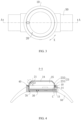
- the wearable device includes a dial plate 10, a watch body 20, and an angle detection member 30.
- the dial plate 10 is provided with an accommodating groove 11.
- the watch body 20 is at least partially disposed in the accommodating groove 11 and is rotatably connected to the dial plate 10, and the watch body 20 is provided with a functional component.
- the angle detection member 30 includes an annular resistor 31 and a conductive connector 32 electrically connected to the annular resistor 31.
- One of the annular resistor 31 and the conductive connector 32 is disposed at the dial plate 10, and the other is disposed at the watch body 20.
- the annular resistor 31 is in sliding connection with the conductive connector 32.
- the functional component is disposed at the watch body 20, and the watch body 20 is rotatably connected to the dial plate 10, so that the functional component can be used at different positions.
- shooting or other functional requirements of the wearable device at different view angles can be achieved.
- the correspondingly disposed angle detection member 30 can be configured to determine a position of the watch body 20 relative to the dial plate 10 by measuring electrical parameters such as a resistance value, which is more conducive to position adjustment of the functional component relative to the dial plate 10.
- the dial plate 10 as a whole may have a circular disk-like structure, and the accommodating groove 11 may be formed through recessing of one end surface of the dial plate 10 in its own axial direction.
- a wall surface surrounding the accommodating groove 11 includes a first side surface 111 and a first bottom surface 112. The first side surface 111 is disposed around the first bottom surface 112.
- the functional component mentioned in the present invention may have various forms, such as an earpiece, a microphone, a speaker, an antenna, a flashlight, an infrared ray, or an imaging component 21, etc.
- the functional component including the imaging component 21 will be described below as specific examples.
- the watch body 20 may include a display screen 24 and a first housing 23.
- the display screen 24 is disposed on a side of the first housing 23 away from the dial plate 10.
- the functional component is displayed on a side of the watch body 20 away from the dial plate 10, and the display screen 24 and the first housing 23 form a first accommodation cavity 25.
- the watch body 20 may be inserted into the accommodating groove 11 of the dial plate 10 through the first housing 23 and rotatably connected to the dial plate 10.
- the watch body 20 is designed in the foregoing form and has a simple structure. Through disposing of the first housing 23 and the display screen 24, the wearable device has a display function while the watch body 20 is rotatably connected to the dial plate 10.
- the first housing 23 has a body part 231 disposed in the accommodating groove 11 and a first protrusion 232 disposed outside the accommodating groove 11. Both the display screen 24 and the functional component are disposed at the first protrusion 232.
- the watch body 20 can be rotatably connected to the dial plate 10, but also the watch body can be locked when rotated to a preset position.
- the first protrusion 232 the user may hold and screw the first protrusion 232 easily, so that the watch body 20 may rotate relative to the dial plate 10.
- the first protrusion 232 has a chamfered structure 232a, and a cross-sectional area of the first protrusion 232 gradually decreases along a direction from an end of the first protrusion 232 proximate to the dial plate 10 to an end of the first protrusion 232 away from the dial plate 10.
- the appearance of the wearable device can be more beautiful, and the user may hold the first protrusion 232 more comfortably.
- the chamfered structure 232a includes a chamfered surface 232b disposed around the display screen 24.
- the functional component including a camera component 21 is still used as an example.
- the camera component 21 is connected to the chamfered structure 232a and a lens faces the chamfered surface 232b.
- An included angle ⁇ between a camera direction of the camera component 21 and a normal direction of a plane where the display screen 24 is located is any numerical value between 30° and 60°, with 30° and 60° included. By disposing the angle, the user can see a picture on the display screen 24 more easily when the camera component 21 is taking a selfie or shooting on location.
- the included angle ⁇ between the camera direction of the camera component 21 and the normal direction of the plane where the display screen 24 is located is any value between 40° and 50°, and the user wears the wearable device on a wrist, the user's arm posture can meet the ergonomics when the user is shooting on location or taking a selfie, and the user may perform shooting comfortably in different shooting functions.
- the included angle ⁇ between the camera direction of the camera component 21 and the normal direction of a plane where the display screen 24 is located is 45°, not only the user can perform shooting comfortably in different shooting functions, but also the user can have a better viewing angle for a photographed object displayed on the display screen 24 during shooting.
- the angle detection member 30 of the wearable device may have various structural forms, which is mainly used for detecting a rotation angle of a watch body 20 relative to a dial plate 10, so as to better control the wearable device.
- the angle detection member 30 detects, when a connection position at which a conductive connector 32 is connected to a ring resistor 31 changes due to rotation of the watch body 20 relative to the dial plate 10, a rotation angle of the watch body 20 relative to the dial plate 10 by changing electrical parameters such as a resistance value of a ring resistor 31 in a detection circuit.
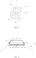
- the annular resistor 31 includes a first annular part 311 and a second annular part 312 which are spaced apart and electrically connected to the conductive connector 32.
- the first annular part 311 and the second annular part 312 are coaxially disposed, and the first annular part 311 is electrically connected to the second annular part 312 through a connecting part 313.
- the ring resistor 31 is designed with the above structure, the reliability of a connection with the conductive connector 32 can be ensured, and a resistance value of the ring resistor 31 connected to the detection circuit through the conductive connector 32 can be better detected, so as to better determine the rotation angle of the watch body 20 relative to the dial plate 10.
- the first annular part 311 has two opposite first free ends 311a in a rotation direction X of the watch body 20, and the second annular part 312 has two opposite second free ends 312a in the rotation direction X.
- the connecting part 313 connects one of the first free ends 311a and one of the second free ends 312a, and the other of the first free ends 311a is disconnected from the other of the second free end 312a.
- the conductive connector 32 includes a first connector 321 and a second connector 322.
- the first connector 321 is electrically connected to the first annular part 311, and the second connector 322 is electrically connected to the second annular part 312.
- both the first connector 321 and the second connector 322 may have contact structures.
- Surfaces of the first connector 321 and the second connector 322 facing the annular resistor 31 are arc surfaces protruding toward the annular resistor 31.
- the conductive connector 32 is disposed at the watch body 20 and the annular resistor 31 is disposed at the dial plate 10.
- an annular open groove 15 may be disposed on the dial plate 10.
- the annular open groove 15 matches the annular resistor 31.
- shapes of the annular open groove and the annular resistor match each other.
- the annular resistor 31 may be disposed in the annular open groove 15.
- the watch body 20 may be provided with a protrusion at least partially located in the annular open groove.
- the conductive connector 32 is disposed on the protrusion and electrically connected to the annular resistor 31.
- the conductive connector 32 and the protrusion may be integrated to form a conductor.
- the conductive connector and the protrusion may be independently processed and interconnected structures.
- an area occupied by the whole angle detection member 30 can be reduced.
- the reliability of a connection between the annular resistor 31 of the angle detection member and the conductive connector 32, between the annular resistor 31 and the corresponding dial plate 10, and between the conductive connector 32 and the watch body 20, can be ensured.
- annular resistor 31 is disposed at the dial plate 10 and the conductive connector 32 is disposed at the watch body 20.
- an annular resistor 31 may be disposed at the watch body 20 and match an annular open groove 15 disposed on the watch body 20, and the conductive connector 32 may be disposed at the watch body 20 and match a protrusion on the watch body 20, which can also meet functional requirements of the angle detection member 30.
- the annular resistor 31 is not limited to matching the annular open groove 15 and disposed in the annular open groove 15.
- the annular resistor 31 may further match a protrusion disposed in the watch body 20 or the dial plate 10 and be disposed at the protrusion, so that the conductive connector 32 matches the annular open groove 15 disposed on the other of the watch body 20 and the dial plate 10, and is disposed in the annular open groove 15. Therefore, the conductive connector 32 is electrically connected to the annular resistor 31 to meet use requirements.
- a first housing 23 of a watch body 20 has a second side surface 233 facing a first side surface 111 of a dial plate 10 and a second bottom surface 234 facing a first bottom surface 112.
- an annular open groove 15 may be formed through recessing from the first bottom surface 112 of the dial plate 10 to a direction away from the watch body 20.
- a radius of a first annular part 311 of an annular resistor 31 is larger than that of a second annular part 312, and a protrusion and a conductive connector 32 are disposed at the second bottom surface 234.
- the annular open groove 15 may further be formed through recessing from the second bottom surface 234 to a direction away from the first bottom surface 112.
- the protrusion and the conductive connector 32 are disposed at the first bottom surface 112, which can meet angle detection requirements of an angle detection member 30.
- the annular open groove 15 may further be formed through recessing from the first side surface 111 to a direction away from the second side surface 233.
- the radius of the first annular part 311 of the annular resistor 31 may be equal to that of the second annular part 312, and the protrusion and the conductive connector 32 may be disposed at the second side surface 233, and the conductive connector 32 may be electrically connected to the annular resistor 31.
- the annular open groove 15 may further be formed through recessing from the second side surface 233 to a direction away from the first side surface 111.
- the protrusion and the conductive connector 32 may be disposed at the first side surface 111 and the conductive connector 32 may be electrically connected to the annular resistor 31, which can still meet angle detection requirements of the angle detection member 30.
- a functional component including a camera component 21 is still used as an example. If you intend to shoot on location and take a selfie, an implementation is performed as follows.
- the camera component 21 may perform shooting at two predetermined positions presenting an included angle. For example, when the wearable device is a clock, the camera component 21 preferably performs shooting at two positions of 6 o'clock and 12 o'clock to better complete shooting on location and taking a selfie. Through the rotational connection between the watch body 20 and the dial plate 10, rotation between them may be reliably achieved, thus meeting requirements of selfie and location shooting.
- the angle detection member 30 is limited in the foregoing manner.
- a rotation angle of the watch body 20 relative to the dial plate 10 may be determined by other electrical parameters such as a resistance value of the annual resistor 31 in the detection circuit, which helps to adjust a position of the camera component 21 and better control the wearable device, for example, control a display direction of a display screen 24 of the wearable device.
- one of a dial plate 10 and a watch body 20 further includes a limiting ball 13 and an elastic member 14 which abut against each other, and the other is provided with a limiting groove 22.
- the limiting ball 13 is at least partially located in the limiting groove 22, the dial plate 10 and the watch body 20 are clamped and fixed through the limiting ball 13 and the limiting groove 22.
- the dial plate 10 and the watch body 20 are clamped and fixed through the limiting ball 13 and the limiting groove 22 when the limiting ball 13 and the elastic member 14 are disposed on one of the dial plate 10 and the watch body 20, and the limiting ball 22 is disposed on the other, so that a functional component may be prevented from rotating relative to the dial plate 10 when it rotates to a predetermined position, and a problem that relative positions of the functional component and the dial plate 10 are difficult to lock is solved.
- the dial plate 10 may include the limiting ball 13 and the elastic member 14, and the dial plate 10 is further provided with an installation groove 12.
- the elastic member 14 is in sliding connection with the installation groove 12, and the elastic member 14 is at least partially located in the installation groove 12.
- a side of the watch body 20 facing the dial plate 10 is provided with a limiting groove 22.
- a position of the functional component can be locked as the watch body 20 rotates to a predetermined position relative to the dial plate 10, and the elastic member 14 and the limiting ball 13 may be installed easily. More importantly, with the foregoing structure, when the functional component needs to rotate to the next position, the user may make the limiting ball 13 separate from the limiting groove 22 by applying a predetermined external force, ensuring position adjustment requirements of the functional component.
- the installation groove 12 on the dial plate 10 may be formed through recessing from a first side surface 111 to a direction away from an accommodating groove 11, and the installation groove 12 and the accommodating groove 11 communicate with each other.
- the formation method is conducive to processing and manufacturing, and can better ensure position locking between the watch body 20 and the dial plate 10.
- the elastic member 14 may be a spring or a spring pad with predetermined deformability, such as a rubber pad.
- a size of an opening of the installation groove 12 is smaller than a diameter of the limiting ball 13, and the limiting ball 13 is located between the watch body 20 and the elastic member 14.
- the limiting ball 13 may be always located in the installation groove 12, avoiding the loss of the elastic member 14 or the limiting ball 13 during assembly or repair of the wearable device or replacement of the dial plate 10 or the watch body 20 with a one having a different color, and being more conducive to assembly and molding of the wearable device.
- limiting grooves 22 there may be more than two limiting grooves 22, and two or more limiting grooves 22 may be spaced apart along a rotation direction X of the watch body 20, or may be uniformly distributed at intervals.
- the wearable device in the foregoing embodiments further includes a rotary connector 40.
- a dial plate 10 and a watch body 20 are rotatably connected to each other through the rotary connector 40.
- the rotary connector 40 includes a rotary guide rail 41 and a guide member 42 which are in cooperation with each other.
- One of the rotary guide rail 41 and the guide member 42 is disposed at the dial plate 10 and the other is disposed at the watch body 20.
- the rotary guide rail 41 extends along a rotation direction X of the watch body 20.
- the watch body 20 can rotate according to a predetermined trajectory when rotating relative to the dial plate 10, thus ensuring the stability of rotation.
- the watch body 20 can be further limited to prevent the watch body 20 from being separated from the accommodating groove 11 of the dial plate 10 when rotating relative to the dial plate 10.
- thickness of the guide member 42 gradually decreases from an end away from the rotary guide rail 41 to an end proximate to the rotary guide rail 41, and a shape of the rotary guide rail 41 matches that of the guide rail 42.
- the watch body 20 includes a second side surface 233 facing a first side surface 111 of the dial plate 10 and a second bottom surface 234 facing a first bottom surface 112 of the dial plate 10. Both the second side surface 233 and the second bottom surface 234 may be located at a body part 231 of the first housing 23.
- the second side surface 233 may be provided with a guide member 42
- the first side surface 111 is provided with a rotary guide rail 41 in sliding connection with the guide member 42.
- the second bottom surface 234 is provided with a guide member 42
- the first bottom surface 112 is provided with a rotary guide rail 41 in sliding connection with the guide rail 42 located on the second bottom surface 234.
- a gap 70 is formed between the first bottom surface 112 and the second bottom surface 234.
- the second side surface 233 is provided with a rotary guide rail 41
- the first side surface 111 is provided with the guide member 42 in sliding connection with the rotary guide rail 41
- the second bottom surface 234 is provided with the rotary guide rail 41
- the first bottom surface 112 is provided with the guide member 42 in sliding connection with the rotary guide rail 41 located on the second bottom surface 234.
- the wearable device in the foregoing embodiments further includes a watch band 50.
- the watch band 50 is connected to the dial plate 10 and can form an openable or buckled fixing ring together with the dial plate 10 through enclosure.
- the wearable device in each embodiment of the present invention further includes a support member 60.
- the support member 60 is disposed between the dial plate 10 and the watch body 20.
- a contact area between the support member 60 and a first bottom surface 112 is larger than that between the support member 60 and a second bottom surface 234.
- the support member 60 may be disposed in the gap 70 and have various structural forms, such as a cone-shaped platform structure.
- a cross-sectional size of the support member 60 gradually decreases along a direction from the first bottom surface 112 to the second bottom surface 234. The structure is simple and more conducive to rotation by the watch body 20 relative to the dial plate 10.
- an embodiment of the present invention further provides a display method applied to a wearable device.
- the wearable device includes a dial plate, a watch body, and an angle detection member.
- the dial plate is provided with an accommodating groove.
- the watch body is at least partially disposed in the accommodating groove and is rotatably connected to the dial plate, and the watch body is provided with a display screen and a camera component.
- the angle detection member includes an annular resistor and a conductive connector electrically connected to the annular resistor.
- One of the annular resistor and the conductive connector is disposed at the dial plate, and the other is disposed at the watch body.
- the annular resistor is in sliding connection with the conductive connector.
- the display method includes the following steps.
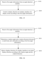
- S100 Receive first angle information from an angle detection member.
- S200 Control a display direction of a display interface of a display screen according to the first angle information.
- the display interface may be always displayed in a direction that is favorable for observation by the user, so that the user has better user experience.
- the wearable device to which the display method provided according to this embodiment of the present invention is applied may be the wearable device in the foregoing embodiments.
- Mechanical structures of the wearable device in this embodiment such as structural forms of a dial plate, a watch body, and an angle detection member and a matching relationship, may be structural forms of the dial plate 10, the watch body 20, and the angle detection member 30 of the wearable device in the foregoing embodiments.
- the wearable device to which the display method is applied is used as an example, such as the wearable device in FIG. 3 to FIG. 14 . The same structure will not be repeated herein.
- the first angle information may be determined according to a structure of the angle detection member 30.
- the first angle information includes at least one of first current information, first voltage information, and first resistance information if the annular resistor 31 is in sliding connection with the conductive connector 32.
- the first current information, the first voltage information, and the first resistance information correspond to an angle between the dial plate 10 and the watch body 20.
- the first angle information may be the first current information, which corresponds to the angle between the dial plate 10 and the watch body 20; (2) the first angle information may be the first voltage information, which corresponds to the angle between the dial plate 10 and the watch body 20; (3) the first angle information may be the first resistance information, which corresponds to the angle between the dial plate 10 and the watch body 20; (4) the first angle information may be the first current information and the first voltage information, both of which correspond to the angle between the dial plate 10 and the watch body 20; (5) the first angle information may be the first current information and the first resistance information, both of which correspond to the angle between the dial plate 10 and the watch body 20; (6) The first angle information may be the first voltage information and the first resistance information, both of which correspond to the angle between the dial plate 10 and the watch body 20; (7) and the first angle information may further be the first current information, first voltage information, and first resistance information, all of which correspond to the angle between the dial plate 10 and the watch body 20.
- step S200 may specifically include the following steps.
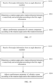
- S201 Determine a rotation angle and a rotation direction between a watch body 20 and a dial plate 10 according to the first angle information.
- S202 Adjust a display direction of a display interface to an initial display direction according to the rotation angle and rotation direction, where the initial display direction is a display direction of the display interface of a display screen 24 when a rotation angle between the watch body 20 and the dial plate 10 is 0°.
- a set rotation angle that is of the watch body 20 relative to the dial plate 10 and that corresponds to the first angle information may be indexed according to at least one of first current information, first voltage information, or the resistance information.
- the rotation angle of the watch body 20 relative to the dial plate 10 is 0°.
- the first resistance information is greater than the initial resistance value, it means that a resistance value of an annular resistor 31 connected to a detection circuit becomes larger, which further means that the watch body 20 has rotated relative to the dial plate 10.
- the rotation angle and rotation direction of the watch body 20 relative to the dial plate 10 may be determined through an obtained resistance value of the first resistance information.
- step S202 if the rotation angle between the watch body 20 and the dial plate 10 may be determined through the first angle information, the display interface of the display screen 24 may be controlled to rotate, so that the display direction of the display interface may be adjusted to the initial display direction, which helps the user check the time, images captured by a camera component 21, or the like.
- S203 Adjust a performance parameter of a camera component 21 according to a rotation angle and/or rotation direction, where the performance parameter includes at least one of resolution, focal length, sharpness, and contrast.
- a position of the camera component 21 may be a location shooting mode.
- the position of the camera component 21 is a selfie mode.
- the position of the camera component 21 may be known, and then the performance parameter of the camera component 21 may be adjusted to match the position, so that a shooting effect can be optimized.
- step S203 may specifically include:
- the shooting mode of the camera component 21 may be known according to the rotation angle and/or rotation direction.
- the shooting mode of the camera component 21 is the location shooting mode.
- Such shooting mode is suitable for shooting scenes, people, or large scenes.
- the watch body 20 rotates to a predetermined angle, for example, 180°, relative to the dial plate 10
- it can be determined that the shooting mode at this time is the selfie mode, and a parameter value of the pixels may be low.
- a corresponding parameter of the camera component 21 may be adjusted only according to the corresponding parameter values. It is easy to control the camera component 21 and shooting effects in different modes can be ensured.
- a location shooting mode or shooting mode corresponding to the rotation of the watch body 20 by 90° relative to the dial plate 10 may be defined as long as a display effect of shooting can be improved.
- step S200 further includes the following step.
- S204 Adjust a display parameter of a display screen 24 according to the rotation angle and/or the rotation direction, where the display parameter includes at least one of brightness, contrast, resolution, hue, and a size of a display interface.
- an embodiment of the present invention further provides a wearable device.
- the wearable device includes a dial plate, a watch body, and an angle detection member.
- the dial plate is provided with an accommodating groove.
- the watch body is at least partially disposed in the accommodating groove and is rotatably connected to the dial plate, and the watch body is provided with a display screen and a camera component.
- the angle detection member includes an annular resistor and a conductive connector electrically connected to the annular resistor.
- One of the annular resistor and the conductive connector is disposed at the dial plate, and the other is disposed at the watch body.
- the annular resistor is in sliding connection with the conductive connector.
- the wearable device further includes a receiving module and a control module 400.
- the receiving module is configured to receive first angle information of an angle detection member.
- the control module 400 is configured to control a display direction of a display interface of a display screen according to the first angle information.
- the wearable device includes the receiving module and the control module 400, the receiving module is configured to receive the first angle information of the angle detection member, and the control module 400 is configured to control the display direction of the display interface of the display screen according to the first angle information, the display interface may be always displayed in a direction that is favorable for observation by the user, so that the user has better user experience.
- Mechanical structures of the wearable device such as the dial plate 10, the watch body 20, and the angle detection member 30, provided according to this embodiment of the present invention, and a cooperative relationship may be structural forms of the dial plate 10, the watch body 20, and the angle detection member 30 of the wearable device provided according to the foregoing embodiments.
- Such mechanical structures may further include the rotary connector 40, the watch band 50, and the gap 70 of the wearable device provided according to the foregoing embodiments, forming any structural form as shown in FIG. 3 to FIG.14 . The same mechanical structure will not be repeated herein.
- the first angle information may be determined according to a structure of the angle detection member 30.
- the first angle information includes at least one of first current information, first voltage information, and first resistance information if the annular resistor 31 is in sliding connection with the conductive connector 32.
- the first current information, the first voltage information, and the first resistance information correspond to an angle between the dial plate 10 and the watch body 20.
- control module 400 may include a determination unit 410 and a first adjustment unit 420.
- the determination unit 410 is configured to determine a rotation angle and rotation direction between the watch body 20 and the dial plate 10 according to the first angle information.
- the first adjustment unit 420 is configured to adjust a display direction of a display interface to an initial display direction according to the rotation angle and rotation direction.
- the initial display direction is a display direction of a display interface of a display screen 24 when a rotation angle between the watch body 20 and the dial plate 10 is 0°.
- the display direction of the display interface of the display screen 24 can be accurately adjusted to the initial display direction, which helps the user watch.
- control module 400 further includes a second adjustment unit 430, which is configured to adjust a performance parameter of a camera component 21 according to the rotation angle and/or rotation direction between the watch body 20 and the dial plate 10.
- the performance parameter includes at least one of resolution, focal length, clarity, and contrast.
- the performance parameter of the camera component 21 can be matched with its position, so as to optimize a shooting effect.
- the second adjustment unit 430 includes a determination subunit 431, an acquisition subunit 432, and an adjustment subunit 433.
- the determination subunit 431 is configured to determine a shooting mode of the camera component 21 according to the rotation angle and/or the rotation direction.
- the acquisition subunit 432 is configured to acquire the parameter value of the performance parameter in a shooting mode.
- the adjustment subunit 433 is configured to adjust the camera component 21 according to the parameter value.
- control module 400 further includes a third adjustment unit 440 which is configured to adjust a display parameter of a display screen 24 according to the rotation angle and/or the rotation direction.
- the display parameter includes at least one of brightness, contrast, resolution, hue, and a size of the display interface.
- an embodiment of the present invention further provides a wearable device 500.
- a structural form of the wearable device may be the structural form shown in FIG. 3 to FIG. 14 according to the foregoing embodiments.
- the wearable device 500 further includes but is not limited to components such as a radio frequency unit 501, a network module 502, an audio output unit 503, an input unit 504, a sensor 505, a display unit 506, a user input unit 507, an interface unit 508, a memory 509, a processor 510, and a power supply 511.
- a radio frequency unit 501 a radio frequency unit 501
- a network module 502 an audio output unit 503, an input unit 504, a sensor 505, a display unit 506, a user input unit 507, an interface unit 508, a memory 509, a processor 510, and a power supply 511.
- the wearable device 21 does not constitute a limitation to a wearable device, and the wearable device may include more or fewer components than those shown in the figure, a combination of some components, or different component arrangements.
- the wearable device includes but is not limited to a smart watch, a wrist band, a wrist strap, a pedometer, or the like.
- the radio frequency unit 501 is configured to receive first angle information of an angle detection member.
- the processor 510 is configured to control a display direction of a display interface of a display screen according to the first angle information.
- the display interface may always be displayed in a direction favorable for the user to observe, so that the user has better user experience.
- the radio frequency unit 501 may be configured to receive and transmit information, or receive and transmit signals during a call. Specifically, the radio frequency unit 501 receives downlink data from a base station, and transmits the downlink data to the processor 510 for processing; and in addition, transmits uplink data to the base station.
- the radio frequency unit 501 includes but is not limited to an antenna, at least one amplifier, a transceiver, a coupler, a low noise amplifier, a duplexer, and the like.
- the radio frequency unit 501 may further communicate with a network and another device by using a wireless communication system.
- the wearable device 500 provides wireless broadband Internet access for the user by using the network module 502, for example, helping the user send and receive an e-mail, browse a web page, and access streaming media.
- the audio output unit 503 may convert audio data received by the radio frequency unit 501 or the network module 502 or stored in the memory 509 to an audio signal and output the audio signal as a sound.
- the audio output unit 503 may further provide an audio output (for example, a call signal received sound or a message received sound) related to a specific function performed by the wearable device 500.
- the audio output unit 503 includes a loudspeaker, a buzzer, a telephone receiver, and the like.
- the input unit 504 is configured to receive an audio signal or a video signal.
- the input unit 504 may include a graphics processing unit (Graphics Processing Unit, GPU) 5041 and a microphone 5042.
- the graphics processing unit 5041 processes image data of a static image or video obtained by an image capture apparatus (such as, a camera) in a video capture mode or an image capture mode.
- a processed image frame may be displayed on the display unit 506.
- the image frame processed by the graphics processing unit 5041 may be stored in the memory 509 (or another storage medium) or sent by using the radio frequency unit 501 or the network module 502.
- the microphone 5042 may receive sound and can process such sound into audio data.
- the processed audio data may be converted in a call mode into a format that may be sent by the radio frequency unit 501 to a mobile communication base station for outputting.
- the wearable device 500 further includes at least one sensor 505, such as a light sensor, a motion sensor, and another sensor.
- the light sensor includes an ambient light sensor and a proximity sensor.
- the ambient light sensor may adjust luminance of a display panel 5061 based on brightness of ambient light.
- the proximity sensor may turn off the display panel 5061 and/or backlight when the wearable device 500 is moved to an ear.
- an accelerometer sensor may detect acceleration values in all directions (generally, three axes), and detect a value and a direction of gravity when the accelerometer sensor is static, and may be used in an application for recognizing a posture of the wearable device (such as horizontal and vertical screen switch, a related game, or magnetometer posture calibration), a function related to vibration recognition (such as a pedometer or a knock), and the like.
- the sensor 505 may further include a fingerprint sensor, a pressure sensor, an iris sensor, a molecular sensor, a gyroscope, a barometer, a hygrometer, a thermometer, an infrared sensor, and the like. Details are not described herein.
- the display unit 506 is configured to display information entered by the user or information provided for the user.
- the display unit 506 may include the display panel 5061, and the display panel 5061 may be configured in a form of a liquid crystal display (Liquid Crystal Display, LCD), an organic light-emitting diode (Organic Light-Emitting Diode, OLED), or the like.
- LCD Liquid Crystal Display
- OLED Organic Light-Emitting Diode
- the user input unit 507 may be configured to receive input digit or character information and generate key signal input related to user setting and function control of the wearable device.
- the user input unit 507 includes a touch panel 5071 and another input device 5072.
- the touch panel 5071 is also referred to as a touchscreen, and may collect a touch operation performed by the user on or near the touch panel 5071 (for example, an operation performed on or near the touch panel 5071 by the user by using any appropriate object or accessory such as a finger or a stylus).
- the touch panel 5071 may include two parts: a touch detection apparatus and a touch controller.
- the touch detection apparatus detects a touch position of the user, detects a signal brought by a touch operation, and transmits the signal to the touch controller.
- the touch controller receives touch information from the touch detection apparatus, converts the touch information into contact coordinates, sends the contact coordinates to the processor 510, and receives and executes a command from the processor 510.
- the touch panel 5071 may be implemented by using a plurality of types such as a resistive type, a capacitive type, an infrared ray type, and a surface acoustic wave type.
- the user input unit 507 may further include another input device 5072 in addition to the touch panel 5071.
- the another input device 5072 may include, but is not limited to, a physical keyboard, function keys (for example, a volume control key and an on/off key), a trackball, a mouse, or a joystick. Details are not described herein.
- the touch panel 5071 may cover the display panel 5061.
- the touch panel 5071 transmits the touch operation to the processor 510 to determine a type of a touch event, and then the processor 510 provides corresponding visual output on the display panel 5061 based on the type of the touch event.
- the touch panel 5071 and the display panel 5061 are configured as two independent components to implement input and output functions of the wearable device, in some embodiments, the touch panel 5071 and the display panel 5061 can be integrated to implement the input and output functions of the wearable device. Details are not limited herein.
- the interface unit 508 is an interface for connecting an external apparatus with the wearable device 100.
- the external apparatus may include a wired or wireless headset port, an external power supply (or a battery charger) port, a wired or wireless data port, a storage card port, a port configured to connect to an apparatus having an identification module, an audio input/output (I/O) port, a video I/O port, a headset port, and the like.
- the interface unit 508 may be configured to: receive an input (for example, data information or power) from the external apparatus, and transmit the received input to one or more elements in the wearable device 100, or may be configured to transmit data between the wearable device 100 and the external apparatus.
- the memory 509 may be configured to store a software program and various data.
- the memory 509 may mainly include a program storage area and a data storage area.
- the program storage area may store an operating system, an application for at least one function (for example, a sound play function or an image play function), and the like.
- the data storage area may store data (for example, audio data or an address book) or the like created based on use of a mobile phone.
- the memory 509 may include a high-speed random access memory, or may include a nonvolatile memory, for example, at least one disk storage device, a flash memory, or another volatile solid-state storage device.
- the processor 510 is a control center of the wearable device.
- the processor 510 uses various interfaces and lines to connect all parts of the entire wearable device, and performs various functions and data proces sing of the wearable device by running or executing the software program and/or module stored in the memory 509 and invoking data stored in the memory 509, thereby performing overall monitoring on the terminal device.
- the processor 510 may include one or more processing units.
- the processor 510 may be integrated with an application processor and a modem processor.
- the application processor mainly processes the operating system, the user interface, applications, etc.
- the modem processor mainly processes wireless communication. It can be understood that, alternatively, the modem processor may not be integrated into the processor 510.
- the wearable device 500 may further include a power supply 511 (for example, a battery) which supplies power to all parts.
- a power supply 511 for example, a battery
- the power supply 511 may be in a logical connection with the processor 510 through a power supply management system, thus conducting functions such as management on charging and discharging and management on power consumption through the power supply management system.
- the wearable device 500 further includes some function modules not shown, and details are not described.
- An embodiment of the present invention further provides a computer-readable storage medium.
- a computer program is stored in the computer-readable storage medium.
- the computer-readable storage medium is, for example, a read-only memory (Read-Only Memory, ROM for short), a random access memory (Random Access Memory, RAM for short), a magnetic disk, or an optical disc.
- the disclosed apparatus and method may be implemented in other manners.
- the apparatus embodiment described above is only an example.
- division into the units is only logical function division.
- There may be other division manners in actual implementation for example, a plurality of units or components may be combined or integrated into another system, or some features may be ignored or not implemented.
- the displayed or discussed mutual couplings or direct couplings or communication connections may be implemented by using some interfaces.
- the indirect couplings or communication connections between the devices or units may be implemented in electronic, mechanical, or other forms.
- the units described as separate components may be or may not be physically separated, and the components displayed as units may be or may not be physical units, that is, may be located in one place or distributed on a plurality of network units. Some or all of the units may be selected according to actual needs to achieve the objective of the solutions of the embodiments.
- the program may be stored in a computer readable storage medium.
- the foregoing storage medium may be a magnetic disk, an optical disc, a read-only memory (Read-Only Memory, ROM), a random access memory (Random Access Memory, RAM), or the like.
- a module, a unit, or a subunit may be implemented in one or more application specific integrated circuits (Application Specific Integrated Circuits, ASIC), digital signal processors (Digital Signal Processor, DSP), digital signal processing devices (DSP Device, DSPD), programmable logic devices (Programmable Logic Device, PLD), field-programmable gate arrays (Field-Programmable Gate Array, FPGA), general purpose processors, controllers, microcontrollers, microprocessors, or other electronic units or a combination thereof used to perform the functions in the present invention.
- ASIC Application Specific Integrated Circuits
- DSP Digital Signal Processor
- DSP Device digital signal processing devices
- PLD programmable logic devices
- FPGA field-programmable gate array
- general purpose processors controllers, microcontrollers, microprocessors, or other electronic units or a combination thereof used to perform the functions in the present invention.
- the technology described in the embodiments of the present invention may be implemented by using a module (for example, a process or a function) that performs the function in the embodiments of the present invention.
- Software codes may be stored in the memory and executed by the processor.
- the memory may be implemented in the processor or outside the processor.
Landscapes
- Physics & Mathematics (AREA)
- General Physics & Mathematics (AREA)
- Engineering & Computer Science (AREA)
- Multimedia (AREA)
- Signal Processing (AREA)
- Theoretical Computer Science (AREA)
- Human Computer Interaction (AREA)
- General Engineering & Computer Science (AREA)
- Computer Hardware Design (AREA)
- Electric Clocks (AREA)
Claims (15)
- Vorrichtung, dadurch gekennzeichnet, dass sie Am Körper tragbarumfasst:ein Ziffernblatt (10), wobei das Ziffernblatt (10) mit einer Aufnahmenut (11) bereitgestellt wird;ein Uhrengehäuse (20), wobei das Uhrengehäuse (20) mindestens teilweise in der Aufnahmenut (11) angeordnet und drehbar mit der Ziffernblattplatte (10) verbunden ist und das Uhrengehäuse (20) mit einer funktionalen Komponente bereitgestellt wird, wobei die funktionale Komponente eine Kamerakomponente (21) umfasst und die Kamerakomponente (21) an verschiedene Positionen in einem Gehäuse angepasst wird, wenn sich das Uhrengehäuse (20) relativ zu der Ziffernblattplatte (10) dreht; undein Winkelerfassungselement (30), umfassend einen ringförmigen Widerstand (31) und einen leitfähigen Verbinder (32), der elektrisch mit dem ringförmigen Widerstand (31) verbunden ist, wobei entweder der ringförmige Widerstand (31) oder der leitfähige Verbinder (32) an dem Ziffernblatt (10) angeordnet ist und der andere am Uhrgehäuse (20) angeordnet ist und der ringförmige Widerstand (31) verschiebbar mit dem leitenden Verbinder (32) verbunden ist; das Winkelerfassungselement (30) so konfiguriert ist, dass es eine Position des Uhrengehäuses (20) relativ zum Ziffernblatt (10) durch Messen elektrischer Parameter festlegt.
- Am Körper tragbare Vorrichtung nach Anspruch 1, wobei der ringförmige Widerstand (31) einen ersten ringförmigen Teil (311) und einen zweiten ringförmigen Teil (312) umfasst, die voneinander beabstandet sind und elektrisch mit dem leitfähigen Verbinder (32) verbunden sind, wobei der erste ringförmige Teil (311) und das zweite ringförmige Teil (312) koaxial angeordnet sind und das erste ringförmige Teil (311) über ein Verbindungsteil (313) mit dem zweiten ringförmigen Teil (312) elektrisch verbunden ist.
- Am Körper tragbare Vorrichtung nach Anspruch 2, wobei der erste ringförmige Teil (311) zwei gegenüberliegende erste freie Enden (311a) in einer Richtung der Drehung des Uhrengehäuses (20) aufweist und der zweite ringförmige Teil (312) zwei gegenüberliegende zweite freie Enden (312a) in der Richtung der Drehung, wobei das Verbindungsteil (313) eines der ersten freien Enden (311a) und eines der zweiten freien Enden (312a) verbindet und das andere der ersten freien Enden (311a) von dem anderen der zweiten freien Enden (312a) getrennt ist.
- Am Körper tragbare Vorrichtung nach Anspruch 2, wobei der leitfähige Verbinder (32) einen ersten Verbinder (321) und einen zweiten Verbinder (322) umfasst, wobei der erste Verbinder (321) elektrisch mit dem ersten ringförmigen Teil (311) verbunden ist , und der zweite Verbinder (322) elektrisch mit dem zweiten ringförmigen Teil (312) verbunden ist, wobei ein Radius des ersten ringförmigen Teils (311) größer oder gleich dem des zweiten ringförmigen Teils (312) ist.
- Am Körper tragbare Vorrichtung nach Anspruch 1, wobei entweder das Ziffernblatt (10) oder das Uhrengehäuse (20) mit einer ringförmigen offenen Nut (15) bereitgestellt wird und das jeweils andere Element, also entweder das Ziffernblatt (10) oder das Uhrengehäuse (20) mit einem Vorsprung bereitgestellt wird, der zu der ringförmigen offenen Nut (15) passt, und der ringförmige Widerstand (31) zu mindestens einem von der ringförmigen offenen Nut (15) und dem Vorsprung passt.
- Am Körper tragbare Vorrichtung nach einem der Ansprüche 1 bis 5, wobei eines von Ziffernblatt (10) und Uhrengehäuse (20) weiter eine Begrenzungskugel (13) und ein elastisches Element (14) umfasst, die aneinander anliegen, und das andere von Ziffernblatt (10) und Uhrengehäuse (20) mit einer Begrenzungsnut (22) bereitgestellt wird und, wenn die Begrenzungskugel (13) mindestens teilweise in der Begrenzungsnut (22) positioniert ist, das Ziffernblatt (10) und das Uhrengehäuse (20) durch die Begrenzungskugel (13) und die Begrenzungsnut (22) geklemmt und fixiert werden.
- Am Körper tragbare Vorrichtung nach Anspruch 6, wobei das Ziffernblatt (10) die Begrenzungskugel (13) und das elastische Element (14) umfasst, eine dem Ziffernblatt (10) gegenüberliegende Seite des Uhrengehäuses (20) mit der Begrenzungsnut (22) bereitgestellt ist, das Ziffernblatt (10) weiter mit einer Installationsnut (12) bereitgestellt ist, das elastische Element (14) in verschiebbarer Verbindung mit der Installationsnut (12) steht und mindestens teilweise in der Installationsnut (12) positioniert ist; wobeiwenn die Installationsnut (12) und die Begrenzungsnut (22) versetzt sind, sich das elastische Element (14) elastisch verformt; oderwenn die Installationsnut (12) der Begrenzungsnut (22) gegenüberliegt, das elastische Element (14) in seine ursprüngliche Form zurückkehrt und sich die Begrenzungskugel (13) mindestens teilweise in der Begrenzungsnut (22) befindet.
- Am Körper tragbare Vorrichtung nach Anspruch 7, wobei die Größe einer Öffnung der Installationsnut (12) kleiner ist als der Durchmesser der Begrenzungskugel (13) und sich die Begrenzungskugel (13) zwischen dem Uhrengehäuse (20) und dem elastischen Element (14) befindet.
- Am Körper tragbare Vorrichtung nach einem der Ansprüche 1 bis 8, weiter umfassend einen Drehverbinder (40), wobei das Ziffernblatt (10) durch den Drehverbinder (40) drehbar mit dem Uhrengehäuse (20) verbunden ist; und
der Drehverbinder (40) eine Drehführungsschiene (41) und ein Führungselement (42) umfasst, die miteinander zusammenwirken, wobei entweder die Drehführungsschiene (41) oder das Führungselement (42) an dem Ziffernblatt (10) angeordnet ist und das andere an dem Uhrengehäuse (20) angeordnet ist. - Anzeigeverfahren, das auf eine am Körper tragbare Vorrichtung angewendet wird, dadurch gekennzeichnet, dass die tragbare Vorrichtung eine Zifferblattplatte, ein Uhrengehäuse und ein Winkelerfassungselement umfasst, wobei die Zifferblattplatte mit einer Aufnahmenut versehen ist, das Uhrengehäuse mindestens teilweise in der Aufnahmenut angeordnet und drehbar mit der Zifferblattplatte verbunden ist und das Uhrengehäuse mit einem Anzeigebildschirm und einer Kamera-Komponente bereitgestellt wird, das Winkelerfassungselement einen ringförmigen Widerstand und einen leitfähigen Verbinder umfasst, der elektrisch mit dem ringförmigen Widerstand verbunden ist, wobei entweder der ringförmige Widerstand oder der leitfähige Verbinder an dem Ziffernblatt angeordnet ist und das jeweils andere Element an dem Uhrgehäuse angeordnet ist und der ringförmige Widerstand in einer Gleitverbindung mit dem leitfähigen Verbinder steht und das Winkelerfassungselement so konfiguriert ist, dass es eine Position des Uhrengehäuses relativ zu dem Ziffernblatt durch Messen elektrischer Parameter festlegt; wobei das Verfahren umfasst:Empfangen (S100) erster Winkelinformationen vom Winkelerfassungselement; undSteuern (S200) einer Anzeigerichtung einer Anzeigefläche des Bildschirms gemäß den ersten Winkelinformationen.
- Verfahren nach Anspruch 10, wobei die ersten Winkelinformationen mindestens eines von ersten Strominformationen, ersten Spannungsinformationen und ersten Widerstandsinformationen umfassen, wenn der ringförmige Widerstand in verschiebbarer Verbindung mit dem leitfähigen Verbinder steht, wobei die ersten Strominformationen, die ersten Spannungsinformationen und die ersten Widerstandsinformationen einem Winkel zwischen dem Ziffernblatt und dem Uhrengehäuse entsprechen.
- Verfahren nach Anspruch 10, wobei die Steuerung (S200) einer Anzeigerichtung einer Anzeigeschnittstelle des Anzeigebildschirms gemäß den ersten Winkelinformationen umfasst:Bestimmen (S201) eines Drehwinkels und einer Drehrichtung zwischen dem Uhrengehäuse und dem Ziffernblatt gemäß den ersten Winkelinformationen; undAnpassen (S202) der Anzeigerichtung der Anzeigeschnittstelle an eine anfängliche Anzeigerichtung gemäß dem Drehwinkel und der Drehrichtung, wobeiwobei die anfängliche Anzeigerichtung eine Anzeigerichtung der Anzeigeschnittstelle des Anzeigebildschirms ist, wenn der Drehwinkel zwischen dem Uhrengehäuse und dem Ziffernblatt 0° beträgt.
- Am Körper tragbare Vorrichtung, umfassend einen Prozessor (510), einen Speicher (509) und ein Computerprogramm, das auf dem Speicher (509) gespeichert ist und auf dem Prozessor (510) ausführbar ist, wobei bei Ausführung des Computerprogramms durch den Prozessor (510) Schritte des Verfahrens nach einem der Ansprüche 10 bis 12 implementiert werden.
- Computerlesbares Speichermedium, wobei das computerlesbare Speichermedium ein Computerprogramm speichert, und wenn das Computerprogramm von einem Prozessor (510) einer am Körper tragbaren Vorrichtung nach Anspruch 13 ausgeführt wird, werden die Schritte des Verfahrens nach einem der Ansprüche 10 bis 12 implementiert.
- Computerprogrammprodukt, wobei das Computerprogrammprodukt in einem nichtflüchtigen Speichermedium gespeichert ist und das Programmprodukt so konfiguriert ist, dass es von mindestens einem Prozessor (510) einer am Körper tragbaren Vorrichtung nach Anspruch 13 ausgeführt wird, sodass die Schritte des Verfahrens nach einem der Ansprüche 10 bis 12 implementiert werden.
Applications Claiming Priority (2)
| Application Number | Priority Date | Filing Date | Title |
|---|---|---|---|
| CN201910900556.9A CN110716420B (zh) | 2019-09-23 | 2019-09-23 | 可穿戴设备及显示方法 |
| PCT/CN2020/106196 WO2021057257A1 (zh) | 2019-09-23 | 2020-07-31 | 可穿戴设备及显示方法 |
Publications (3)
| Publication Number | Publication Date |
|---|---|
| EP4036661A1 EP4036661A1 (de) | 2022-08-03 |
| EP4036661A4 EP4036661A4 (de) | 2022-11-16 |
| EP4036661B1 true EP4036661B1 (de) | 2025-03-05 |
Family
ID=69209998
Family Applications (1)
| Application Number | Title | Priority Date | Filing Date |
|---|---|---|---|
| EP20869456.2A Active EP4036661B1 (de) | 2019-09-23 | 2020-07-31 | Am körper tragbare vorrichtung und anzeigeverfahren |
Country Status (5)
| Country | Link |
|---|---|
| US (1) | US12143706B2 (de) |
| EP (1) | EP4036661B1 (de) |
| CN (1) | CN110716420B (de) |
| ES (1) | ES3019482T3 (de) |
| WO (1) | WO2021057257A1 (de) |
Families Citing this family (10)
| Publication number | Priority date | Publication date | Assignee | Title |
|---|---|---|---|---|
| CN110737190A (zh) * | 2019-09-23 | 2020-01-31 | 维沃移动通信有限公司 | 可穿戴设备及显示方法 |
| CN110716420B (zh) * | 2019-09-23 | 2020-11-10 | 维沃移动通信有限公司 | 可穿戴设备及显示方法 |
| CN111352559B (zh) * | 2020-02-27 | 2021-07-13 | 维沃移动通信有限公司 | 一种电子设备及控制方法 |
| CN111338203B (zh) | 2020-02-27 | 2021-07-23 | 维沃移动通信有限公司 | 一种电子设备及控制方法 |
| CN111897445A (zh) * | 2020-07-30 | 2020-11-06 | 维沃移动通信有限公司 | 电子设备及控制方法 |
| CN112506025B (zh) * | 2020-11-24 | 2022-03-22 | 维沃移动通信有限公司 | 可穿戴设备及其拍摄方法 |
| CN112804422B (zh) * | 2020-12-28 | 2022-04-15 | 维沃移动通信有限公司 | 电子设备及其摄像头模组 |
| CN112689074B (zh) * | 2020-12-28 | 2022-07-15 | 维沃移动通信有限公司 | 电子设备及其摄像头模组 |
| US20230091991A1 (en) * | 2021-09-23 | 2023-03-23 | Apple Inc. | Wearable electronic device having a digital camera assembly |
| CN115551156B (zh) * | 2022-03-01 | 2023-10-31 | 荣耀终端有限公司 | 一种发光闪烁的方法及可穿戴设备 |
Family Cites Families (27)
| Publication number | Priority date | Publication date | Assignee | Title |
|---|---|---|---|---|
| CH688950B5 (fr) | 1995-08-22 | 1998-12-31 | Ebauchesfabrik Eta Ag | Dispositif de synchronisation d'un affichage analogique avec un compteur électronique dans une pièce d'horlogerie. |
| JP3437062B2 (ja) * | 1997-08-14 | 2003-08-18 | 株式会社小糸製作所 | パワーウインドの安全装置 |
| JP2000274142A (ja) * | 1999-03-23 | 2000-10-03 | Koito Mfg Co Ltd | パワーウインドの安全装置 |
| JP2003344573A (ja) * | 2002-05-24 | 2003-12-03 | Seiko Instruments Inc | 電子時計 |
| CN200968856Y (zh) * | 2006-10-17 | 2007-10-31 | 张敏俐 | 角度仪 |
| KR102138503B1 (ko) * | 2013-04-09 | 2020-07-28 | 엘지전자 주식회사 | 스마트 워치 |
| JP6171615B2 (ja) * | 2013-06-21 | 2017-08-02 | カシオ計算機株式会社 | 情報処理装置及びプログラム |
| KR102163915B1 (ko) * | 2013-09-02 | 2020-10-12 | 엘지전자 주식회사 | 스마트 와치 및 제어 방법 |
| EP2891942B1 (de) * | 2014-01-02 | 2018-08-22 | LG Electronics Inc. | Tragbares Endgerät |
| CN104315970A (zh) | 2014-10-29 | 2015-01-28 | 北京可以科技有限公司 | 一种基于双电位器的无死区角度测量装置及测量方法 |
| US9557717B2 (en) * | 2014-11-26 | 2017-01-31 | Hisense Usa Corp. | Devices and methods for automatic adjustment of display elements |
| CN105389074A (zh) * | 2015-07-28 | 2016-03-09 | 广东欧珀移动通信有限公司 | 一种智能手表的控制方法及智能手表 |
| CN104977845B (zh) * | 2015-08-06 | 2018-01-16 | 惠州Tcl移动通信有限公司 | 一种表壳组件、智能手表及智能手表的控制方法 |
| KR20170040922A (ko) * | 2015-10-06 | 2017-04-14 | 삼성전자주식회사 | 회전 입력 측정 방법 및 장치 |
| CN105675185A (zh) * | 2016-04-24 | 2016-06-15 | 无锡职业技术学院 | 一种基于stm8单片机的机械式多功能智能压力仪表 |
| US10551798B1 (en) * | 2016-05-17 | 2020-02-04 | Apple Inc. | Rotatable crown for an electronic device |
| CN205809552U (zh) * | 2016-06-21 | 2016-12-14 | 何屹 | 一种手表的360度旋转摄像头结构 |
| CN106325055B (zh) * | 2016-08-16 | 2020-05-01 | 努比亚技术有限公司 | 一种智能手表相机参数的调节方法及和装置 |
| CN206270672U (zh) | 2016-10-27 | 2017-06-20 | 深圳市健云互联科技有限公司 | 一种带有可360度旋转摄像头的智能手表 |
| CH713251B1 (fr) * | 2016-12-16 | 2020-11-30 | Eta Sa Mft Horlogere Suisse | Boîte de montre avec molette de commande. |
| KR102355149B1 (ko) * | 2017-04-25 | 2022-01-25 | 삼성전자주식회사 | 분리형 입력 장치를 포함하는 전자 장치 |
| CN107289919A (zh) * | 2017-06-01 | 2017-10-24 | 西安交通大学 | 一种环形电阻式mems液体角度陀螺仪 |
| CN207976717U (zh) * | 2018-01-10 | 2018-10-16 | 何屹 | 360度旋转摄像手表 |
| CN208283732U (zh) | 2018-07-02 | 2018-12-25 | 广东小天才科技有限公司 | 一种具有旋转摄像头的智能手表 |
| CN108732913A (zh) | 2018-08-14 | 2018-11-02 | 广东小天才科技有限公司 | 一种具有可旋转式投影装置的智能手表及其使用方法 |
| KR102613736B1 (ko) * | 2019-05-23 | 2023-12-14 | 삼성전자주식회사 | 시선 전환이 가능한 카메라 모듈을 포함하는 전자 장치 및 그의 동영상을 기록하는 방법 |
| CN110716420B (zh) * | 2019-09-23 | 2020-11-10 | 维沃移动通信有限公司 | 可穿戴设备及显示方法 |
-
2019
- 2019-09-23 CN CN201910900556.9A patent/CN110716420B/zh active Active
-
2020
- 2020-07-31 EP EP20869456.2A patent/EP4036661B1/de active Active
- 2020-07-31 ES ES20869456T patent/ES3019482T3/es active Active
- 2020-07-31 WO PCT/CN2020/106196 patent/WO2021057257A1/zh not_active Ceased
-
2022
- 2022-03-04 US US17/687,383 patent/US12143706B2/en active Active
Also Published As
| Publication number | Publication date |
|---|---|
| CN110716420A (zh) | 2020-01-21 |
| US20220191387A1 (en) | 2022-06-16 |
| ES3019482T3 (en) | 2025-05-20 |
| WO2021057257A1 (zh) | 2021-04-01 |
| US12143706B2 (en) | 2024-11-12 |
| EP4036661A4 (de) | 2022-11-16 |
| EP4036661A1 (de) | 2022-08-03 |
| CN110716420B (zh) | 2020-11-10 |
Similar Documents
| Publication | Publication Date | Title |
|---|---|---|
| US12143706B2 (en) | Wearable device and display method | |
| US11983036B2 (en) | Wearable device and display method | |
| CN108259716B (zh) | 相机模块和包括该相机模块的电子设备 | |
| EP4156705B1 (de) | Elektronische vorrichtung mit aufklapp- und drehkamera | |
| EP2922149B1 (de) | Audiobuchse, elektronische Einrichtung und elektronisches System | |
| CN210899362U (zh) | 摄像头模组及电子设备 | |
| KR20220017078A (ko) | 화면 회전을 제어하기 위한 폴더블 전자 장치 및 그의 동작 방법 | |
| CN110737190A (zh) | 可穿戴设备及显示方法 | |
| US12101427B2 (en) | Mobile terminal, electronic device comprising mobile terminal, and method for controlling electronic device | |
| CN108696688A (zh) | 一种摄像头、终端及拍摄方法 | |
| US12547123B2 (en) | Electronic device and control method | |
| CN114153334B (zh) | 电子设备及其控制方法和控制装置 | |
| EP4174619A1 (de) | Elektronische vorrichtung zur erfassung der feuchtigkeitseinleitung und betriebsverfahren dafür | |
| CN109144455B (zh) | 显示控制方法及相关产品 | |
| EP4113266B1 (de) | Elektronische vorrichtung und steuerverfahren | |
| CN213028238U (zh) | 云台摄像装置和移动终端 | |
| CN113923323B (zh) | 电子设备及其控制方法、控制装置 | |
| KR102052972B1 (ko) | 와치형 이동단말기 | |
| CN108111721B (zh) | 摄像头的支架组件、芯片组件、摄像头及电子设备 | |
| CN110875544B (zh) | 一种折叠连接器和终端 | |
| CN111025879A (zh) | 一种防水转接弹片结构及可穿戴设备 | |
| KR20140144544A (ko) | 와치형 이동단말기 | |
| KR20210145395A (ko) | 압력 센서 모듈을 포함하는 전자 장치 | |
| HK1263153A1 (en) | Electronic device having usb type-c interface | |
| HK1263153B (en) | Electronic device having usb type-c interface |
Legal Events
| Date | Code | Title | Description |
|---|---|---|---|
| STAA | Information on the status of an ep patent application or granted ep patent |
Free format text: STATUS: THE INTERNATIONAL PUBLICATION HAS BEEN MADE |
|
| PUAI | Public reference made under article 153(3) epc to a published international application that has entered the european phase |
Free format text: ORIGINAL CODE: 0009012 |
|
| STAA | Information on the status of an ep patent application or granted ep patent |
Free format text: STATUS: REQUEST FOR EXAMINATION WAS MADE |
|
| 17P | Request for examination filed |
Effective date: 20220412 |
|
| AK | Designated contracting states |
Kind code of ref document: A1 Designated state(s): AL AT BE BG CH CY CZ DE DK EE ES FI FR GB GR HR HU IE IS IT LI LT LU LV MC MK MT NL NO PL PT RO RS SE SI SK SM TR |
|
| A4 | Supplementary search report drawn up and despatched |
Effective date: 20221014 |
|
| RIC1 | Information provided on ipc code assigned before grant |
Ipc: G04C 3/00 20060101ALI20221010BHEP Ipc: G04B 19/06 20060101ALI20221010BHEP Ipc: G04B 47/06 20060101ALI20221010BHEP Ipc: G04G 21/00 20100101ALI20221010BHEP Ipc: G04G 21/02 20100101ALI20221010BHEP Ipc: G04G 17/00 20130101AFI20221010BHEP |
|
| DAV | Request for validation of the european patent (deleted) | ||
| DAX | Request for extension of the european patent (deleted) | ||
| REG | Reference to a national code |
Ref country code: DE Ref legal event code: R079 Free format text: PREVIOUS MAIN CLASS: G04G0017000000 Ipc: G04G0021040000 Ref document number: 602020047397 Country of ref document: DE |
|
| GRAP | Despatch of communication of intention to grant a patent |
Free format text: ORIGINAL CODE: EPIDOSNIGR1 |
|
| STAA | Information on the status of an ep patent application or granted ep patent |
Free format text: STATUS: GRANT OF PATENT IS INTENDED |
|
| RIC1 | Information provided on ipc code assigned before grant |
Ipc: G04G 21/06 20100101ALI20241206BHEP Ipc: G04G 21/04 20130101AFI20241206BHEP |
|
| INTG | Intention to grant announced |
Effective date: 20241219 |
|
| RIN1 | Information on inventor provided before grant (corrected) |
Inventor name: ZHENG, CAIYIN |
|
| GRAS | Grant fee paid |
Free format text: ORIGINAL CODE: EPIDOSNIGR3 |
|
| GRAA | (expected) grant |
Free format text: ORIGINAL CODE: 0009210 |
|
| STAA | Information on the status of an ep patent application or granted ep patent |
Free format text: STATUS: THE PATENT HAS BEEN GRANTED |
|
| AK | Designated contracting states |
Kind code of ref document: B1 Designated state(s): AL AT BE BG CH CY CZ DE DK EE ES FI FR GB GR HR HU IE IS IT LI LT LU LV MC MK MT NL NO PL PT RO RS SE SI SK SM TR |
|
| REG | Reference to a national code |
Ref country code: GB Ref legal event code: FG4D |
|
| REG | Reference to a national code |
Ref country code: CH Ref legal event code: EP |
|
| REG | Reference to a national code |
Ref country code: IE Ref legal event code: FG4D |
|
| REG | Reference to a national code |
Ref country code: DE Ref legal event code: R096 Ref document number: 602020047397 Country of ref document: DE |
|
| REG | Reference to a national code |
Ref country code: NL Ref legal event code: FP |
|
| REG | Reference to a national code |
Ref country code: ES Ref legal event code: FG2A Ref document number: 3019482 Country of ref document: ES Kind code of ref document: T3 Effective date: 20250520 |
|
| PG25 | Lapsed in a contracting state [announced via postgrant information from national office to epo] |
Ref country code: RS Free format text: LAPSE BECAUSE OF FAILURE TO SUBMIT A TRANSLATION OF THE DESCRIPTION OR TO PAY THE FEE WITHIN THE PRESCRIBED TIME-LIMIT Effective date: 20250605 |
|
| PG25 | Lapsed in a contracting state [announced via postgrant information from national office to epo] |
Ref country code: FI Free format text: LAPSE BECAUSE OF FAILURE TO SUBMIT A TRANSLATION OF THE DESCRIPTION OR TO PAY THE FEE WITHIN THE PRESCRIBED TIME-LIMIT Effective date: 20250305 |
|
| REG | Reference to a national code |
Ref country code: LT Ref legal event code: MG9D |
|
| PG25 | Lapsed in a contracting state [announced via postgrant information from national office to epo] |
Ref country code: NO Free format text: LAPSE BECAUSE OF FAILURE TO SUBMIT A TRANSLATION OF THE DESCRIPTION OR TO PAY THE FEE WITHIN THE PRESCRIBED TIME-LIMIT Effective date: 20250605 |
|
| PG25 | Lapsed in a contracting state [announced via postgrant information from national office to epo] |
Ref country code: HR Free format text: LAPSE BECAUSE OF FAILURE TO SUBMIT A TRANSLATION OF THE DESCRIPTION OR TO PAY THE FEE WITHIN THE PRESCRIBED TIME-LIMIT Effective date: 20250305 |
|
| PG25 | Lapsed in a contracting state [announced via postgrant information from national office to epo] |
Ref country code: LV Free format text: LAPSE BECAUSE OF FAILURE TO SUBMIT A TRANSLATION OF THE DESCRIPTION OR TO PAY THE FEE WITHIN THE PRESCRIBED TIME-LIMIT Effective date: 20250305 |
|
| PG25 | Lapsed in a contracting state [announced via postgrant information from national office to epo] |
Ref country code: BG Free format text: LAPSE BECAUSE OF FAILURE TO SUBMIT A TRANSLATION OF THE DESCRIPTION OR TO PAY THE FEE WITHIN THE PRESCRIBED TIME-LIMIT Effective date: 20250305 Ref country code: GR Free format text: LAPSE BECAUSE OF FAILURE TO SUBMIT A TRANSLATION OF THE DESCRIPTION OR TO PAY THE FEE WITHIN THE PRESCRIBED TIME-LIMIT Effective date: 20250606 |
|
| REG | Reference to a national code |
Ref country code: AT Ref legal event code: MK05 Ref document number: 1773457 Country of ref document: AT Kind code of ref document: T Effective date: 20250305 |
|
| PG25 | Lapsed in a contracting state [announced via postgrant information from national office to epo] |
Ref country code: SE Free format text: LAPSE BECAUSE OF FAILURE TO SUBMIT A TRANSLATION OF THE DESCRIPTION OR TO PAY THE FEE WITHIN THE PRESCRIBED TIME-LIMIT Effective date: 20250305 |
|
| PG25 | Lapsed in a contracting state [announced via postgrant information from national office to epo] |
Ref country code: SM Free format text: LAPSE BECAUSE OF FAILURE TO SUBMIT A TRANSLATION OF THE DESCRIPTION OR TO PAY THE FEE WITHIN THE PRESCRIBED TIME-LIMIT Effective date: 20250305 |
|
| PG25 | Lapsed in a contracting state [announced via postgrant information from national office to epo] |
Ref country code: PT Free format text: LAPSE BECAUSE OF FAILURE TO SUBMIT A TRANSLATION OF THE DESCRIPTION OR TO PAY THE FEE WITHIN THE PRESCRIBED TIME-LIMIT Effective date: 20250707 |
|
| PGFP | Annual fee paid to national office [announced via postgrant information from national office to epo] |
Ref country code: ES Payment date: 20250804 Year of fee payment: 6 |
|
| PGFP | Annual fee paid to national office [announced via postgrant information from national office to epo] |
Ref country code: DE Payment date: 20250604 Year of fee payment: 6 |
|
| PG25 | Lapsed in a contracting state [announced via postgrant information from national office to epo] |
Ref country code: PL Free format text: LAPSE BECAUSE OF FAILURE TO SUBMIT A TRANSLATION OF THE DESCRIPTION OR TO PAY THE FEE WITHIN THE PRESCRIBED TIME-LIMIT Effective date: 20250305 |
|
| PG25 | Lapsed in a contracting state [announced via postgrant information from national office to epo] |
Ref country code: AT Free format text: LAPSE BECAUSE OF FAILURE TO SUBMIT A TRANSLATION OF THE DESCRIPTION OR TO PAY THE FEE WITHIN THE PRESCRIBED TIME-LIMIT Effective date: 20250305 |
|
| PG25 | Lapsed in a contracting state [announced via postgrant information from national office to epo] |
Ref country code: CZ Free format text: LAPSE BECAUSE OF FAILURE TO SUBMIT A TRANSLATION OF THE DESCRIPTION OR TO PAY THE FEE WITHIN THE PRESCRIBED TIME-LIMIT Effective date: 20250305 Ref country code: EE Free format text: LAPSE BECAUSE OF FAILURE TO SUBMIT A TRANSLATION OF THE DESCRIPTION OR TO PAY THE FEE WITHIN THE PRESCRIBED TIME-LIMIT Effective date: 20250305 |
|
| PG25 | Lapsed in a contracting state [announced via postgrant information from national office to epo] |
Ref country code: RO Free format text: LAPSE BECAUSE OF FAILURE TO SUBMIT A TRANSLATION OF THE DESCRIPTION OR TO PAY THE FEE WITHIN THE PRESCRIBED TIME-LIMIT Effective date: 20250305 |
|
| PG25 | Lapsed in a contracting state [announced via postgrant information from national office to epo] |
Ref country code: SK Free format text: LAPSE BECAUSE OF FAILURE TO SUBMIT A TRANSLATION OF THE DESCRIPTION OR TO PAY THE FEE WITHIN THE PRESCRIBED TIME-LIMIT Effective date: 20250305 |
|
| PG25 | Lapsed in a contracting state [announced via postgrant information from national office to epo] |
Ref country code: IS Free format text: LAPSE BECAUSE OF FAILURE TO SUBMIT A TRANSLATION OF THE DESCRIPTION OR TO PAY THE FEE WITHIN THE PRESCRIBED TIME-LIMIT Effective date: 20250705 |
|
| REG | Reference to a national code |
Ref country code: DE Ref legal event code: R097 Ref document number: 602020047397 Country of ref document: DE |
|
| PLBE | No opposition filed within time limit |
Free format text: ORIGINAL CODE: 0009261 |
|
| STAA | Information on the status of an ep patent application or granted ep patent |
Free format text: STATUS: NO OPPOSITION FILED WITHIN TIME LIMIT |
|
| PG25 | Lapsed in a contracting state [announced via postgrant information from national office to epo] |
Ref country code: DK Free format text: LAPSE BECAUSE OF FAILURE TO SUBMIT A TRANSLATION OF THE DESCRIPTION OR TO PAY THE FEE WITHIN THE PRESCRIBED TIME-LIMIT Effective date: 20250305 |
|
| REG | Reference to a national code |
Ref country code: CH Ref legal event code: L10 Free format text: ST27 STATUS EVENT CODE: U-0-0-L10-L00 (AS PROVIDED BY THE NATIONAL OFFICE) Effective date: 20260114 |
|
| 26N | No opposition filed |
Effective date: 20251208 |
|
| REG | Reference to a national code |
Ref country code: CH Ref legal event code: H13 Free format text: ST27 STATUS EVENT CODE: U-0-0-H10-H13 (AS PROVIDED BY THE NATIONAL OFFICE) Effective date: 20260224 |
|
| PG25 | Lapsed in a contracting state [announced via postgrant information from national office to epo] |
Ref country code: LU Free format text: LAPSE BECAUSE OF NON-PAYMENT OF DUE FEES Effective date: 20250731 |
|
| REG | Reference to a national code |
Ref country code: BE Ref legal event code: MM Effective date: 20250731 |
|
| PG25 | Lapsed in a contracting state [announced via postgrant information from national office to epo] |
Ref country code: BE Free format text: LAPSE BECAUSE OF NON-PAYMENT OF DUE FEES Effective date: 20250731 |
|
| PG25 | Lapsed in a contracting state [announced via postgrant information from national office to epo] |
Ref country code: CH Free format text: LAPSE BECAUSE OF NON-PAYMENT OF DUE FEES Effective date: 20250731 |
|
| PG25 | Lapsed in a contracting state [announced via postgrant information from national office to epo] |
Ref country code: LT Free format text: LAPSE BECAUSE OF FAILURE TO SUBMIT A TRANSLATION OF THE DESCRIPTION OR TO PAY THE FEE WITHIN THE PRESCRIBED TIME-LIMIT Effective date: 20250305 |
|
| PGFP | Annual fee paid to national office [announced via postgrant information from national office to epo] |
Ref country code: GB Payment date: 20260615 Year of fee payment: 7 |
|
| PGFP | Annual fee paid to national office [announced via postgrant information from national office to epo] |
Ref country code: IT Payment date: 20260622 Year of fee payment: 7 |
|
| PG25 | Lapsed in a contracting state [announced via postgrant information from national office to epo] |
Ref country code: IE Free format text: LAPSE BECAUSE OF NON-PAYMENT OF DUE FEES Effective date: 20250731 |
|
| PG25 | Lapsed in a contracting state [announced via postgrant information from national office to epo] |
Ref country code: MC Free format text: LAPSE BECAUSE OF FAILURE TO SUBMIT A TRANSLATION OF THE DESCRIPTION OR TO PAY THE FEE WITHIN THE PRESCRIBED TIME-LIMIT Effective date: 20250305 |
|
| PGFP | Annual fee paid to national office [announced via postgrant information from national office to epo] |
Ref country code: NL Payment date: 20260615 Year of fee payment: 7 |
|
| PGFP | Annual fee paid to national office [announced via postgrant information from national office to epo] |
Ref country code: FR Payment date: 20260608 Year of fee payment: 7 |
|
| PG25 | Lapsed in a contracting state [announced via postgrant information from national office to epo] |
Ref country code: CY Free format text: LAPSE BECAUSE OF FAILURE TO SUBMIT A TRANSLATION OF THE DESCRIPTION OR TO PAY THE FEE WITHIN THE PRESCRIBED TIME-LIMIT Effective date: 20250305 |