EP4036624A1 - Dispositif électroluminescent, unité de conversion de longueur d'onde, et phare ou dispositif d'affichage - Google Patents
Dispositif électroluminescent, unité de conversion de longueur d'onde, et phare ou dispositif d'affichage Download PDFInfo
- Publication number
- EP4036624A1 EP4036624A1 EP20869693.0A EP20869693A EP4036624A1 EP 4036624 A1 EP4036624 A1 EP 4036624A1 EP 20869693 A EP20869693 A EP 20869693A EP 4036624 A1 EP4036624 A1 EP 4036624A1
- Authority
- EP
- European Patent Office
- Prior art keywords
- light
- wavelength conversion
- heat dissipation
- emitting device
- dissipation member
- Prior art date
- Legal status (The legal status is an assumption and is not a legal conclusion. Google has not performed a legal analysis and makes no representation as to the accuracy of the status listed.)
- Pending
Links
Images


Classifications
-
- H—ELECTRICITY
- H10—SEMICONDUCTOR DEVICES; ELECTRIC SOLID-STATE DEVICES NOT OTHERWISE PROVIDED FOR
- H10H—INORGANIC LIGHT-EMITTING SEMICONDUCTOR DEVICES HAVING POTENTIAL BARRIERS
- H10H20/00—Individual inorganic light-emitting semiconductor devices having potential barriers, e.g. light-emitting diodes [LED]
- H10H20/80—Constructional details
- H10H20/85—Packages
- H10H20/851—Wavelength conversion means
- H10H20/8514—Wavelength conversion means characterised by their shape, e.g. plate or foil
-
- H—ELECTRICITY
- H10—SEMICONDUCTOR DEVICES; ELECTRIC SOLID-STATE DEVICES NOT OTHERWISE PROVIDED FOR
- H10H—INORGANIC LIGHT-EMITTING SEMICONDUCTOR DEVICES HAVING POTENTIAL BARRIERS
- H10H20/00—Individual inorganic light-emitting semiconductor devices having potential barriers, e.g. light-emitting diodes [LED]
- H10H20/80—Constructional details
- H10H20/85—Packages
- H10H20/858—Means for heat extraction or cooling
- H10H20/8583—Means for heat extraction or cooling not being in contact with the bodies
-
- F—MECHANICAL ENGINEERING; LIGHTING; HEATING; WEAPONS; BLASTING
- F21—LIGHTING
- F21S—NON-PORTABLE LIGHTING DEVICES; SYSTEMS THEREOF; VEHICLE LIGHTING DEVICES SPECIALLY ADAPTED FOR VEHICLE EXTERIORS
- F21S41/00—Illuminating devices specially adapted for vehicle exteriors, e.g. headlamps
- F21S41/10—Illuminating devices specially adapted for vehicle exteriors, e.g. headlamps characterised by the light source
- F21S41/14—Illuminating devices specially adapted for vehicle exteriors, e.g. headlamps characterised by the light source characterised by the type of light source
- F21S41/16—Laser light sources
-
- F—MECHANICAL ENGINEERING; LIGHTING; HEATING; WEAPONS; BLASTING
- F21—LIGHTING
- F21S—NON-PORTABLE LIGHTING DEVICES; SYSTEMS THEREOF; VEHICLE LIGHTING DEVICES SPECIALLY ADAPTED FOR VEHICLE EXTERIORS
- F21S41/00—Illuminating devices specially adapted for vehicle exteriors, e.g. headlamps
- F21S41/10—Illuminating devices specially adapted for vehicle exteriors, e.g. headlamps characterised by the light source
- F21S41/14—Illuminating devices specially adapted for vehicle exteriors, e.g. headlamps characterised by the light source characterised by the type of light source
- F21S41/176—Light sources where the light is generated by photoluminescent material spaced from a primary light generating element
-
- F—MECHANICAL ENGINEERING; LIGHTING; HEATING; WEAPONS; BLASTING
- F21—LIGHTING
- F21S—NON-PORTABLE LIGHTING DEVICES; SYSTEMS THEREOF; VEHICLE LIGHTING DEVICES SPECIALLY ADAPTED FOR VEHICLE EXTERIORS
- F21S43/00—Signalling devices specially adapted for vehicle exteriors, e.g. brake lamps, direction indicator lights or reversing lights
- F21S43/10—Signalling devices specially adapted for vehicle exteriors, e.g. brake lamps, direction indicator lights or reversing lights characterised by the light source
- F21S43/13—Signalling devices specially adapted for vehicle exteriors, e.g. brake lamps, direction indicator lights or reversing lights characterised by the light source characterised by the type of light source
- F21S43/16—Light sources where the light is generated by photoluminescent material spaced from a primary light generating element
-
- F—MECHANICAL ENGINEERING; LIGHTING; HEATING; WEAPONS; BLASTING
- F21—LIGHTING
- F21S—NON-PORTABLE LIGHTING DEVICES; SYSTEMS THEREOF; VEHICLE LIGHTING DEVICES SPECIALLY ADAPTED FOR VEHICLE EXTERIORS
- F21S45/00—Arrangements within vehicle lighting devices specially adapted for vehicle exteriors, for purposes other than emission or distribution of light
- F21S45/40—Cooling of lighting devices
- F21S45/47—Passive cooling, e.g. using fins, thermal conductive elements or openings
-
- F—MECHANICAL ENGINEERING; LIGHTING; HEATING; WEAPONS; BLASTING
- F21—LIGHTING
- F21V—FUNCTIONAL FEATURES OR DETAILS OF LIGHTING DEVICES OR SYSTEMS THEREOF; STRUCTURAL COMBINATIONS OF LIGHTING DEVICES WITH OTHER ARTICLES, NOT OTHERWISE PROVIDED FOR
- F21V29/00—Protecting lighting devices from thermal damage; Cooling or heating arrangements specially adapted for lighting devices or systems
- F21V29/50—Cooling arrangements
- F21V29/502—Cooling arrangements characterised by the adaptation for cooling of specific components
-
- H—ELECTRICITY
- H01—ELECTRIC ELEMENTS
- H01S—DEVICES USING THE PROCESS OF LIGHT AMPLIFICATION BY STIMULATED EMISSION OF RADIATION [LASER] TO AMPLIFY OR GENERATE LIGHT; DEVICES USING STIMULATED EMISSION OF ELECTROMAGNETIC RADIATION IN WAVE RANGES OTHER THAN OPTICAL
- H01S5/00—Semiconductor lasers
- H01S5/005—Optical components external to the laser cavity, specially adapted therefor, e.g. for homogenisation or merging of the beams or for manipulating laser pulses, e.g. pulse shaping
- H01S5/0087—Optical components external to the laser cavity, specially adapted therefor, e.g. for homogenisation or merging of the beams or for manipulating laser pulses, e.g. pulse shaping for illuminating phosphorescent or fluorescent materials, e.g. using optical arrangements specifically adapted for guiding or shaping laser beams illuminating these materials
-
- H—ELECTRICITY
- H01—ELECTRIC ELEMENTS
- H01S—DEVICES USING THE PROCESS OF LIGHT AMPLIFICATION BY STIMULATED EMISSION OF RADIATION [LASER] TO AMPLIFY OR GENERATE LIGHT; DEVICES USING STIMULATED EMISSION OF ELECTROMAGNETIC RADIATION IN WAVE RANGES OTHER THAN OPTICAL
- H01S5/00—Semiconductor lasers
- H01S5/02—Structural details or components not essential to laser action
- H01S5/022—Mountings; Housings
- H01S5/0225—Out-coupling of light
- H01S5/02257—Out-coupling of light using windows, e.g. specially adapted for back-reflecting light to a detector inside the housing
-
- H—ELECTRICITY
- H01—ELECTRIC ELEMENTS
- H01S—DEVICES USING THE PROCESS OF LIGHT AMPLIFICATION BY STIMULATED EMISSION OF RADIATION [LASER] TO AMPLIFY OR GENERATE LIGHT; DEVICES USING STIMULATED EMISSION OF ELECTROMAGNETIC RADIATION IN WAVE RANGES OTHER THAN OPTICAL
- H01S5/00—Semiconductor lasers
- H01S5/02—Structural details or components not essential to laser action
- H01S5/024—Arrangements for thermal management
-
- H—ELECTRICITY
- H01—ELECTRIC ELEMENTS
- H01S—DEVICES USING THE PROCESS OF LIGHT AMPLIFICATION BY STIMULATED EMISSION OF RADIATION [LASER] TO AMPLIFY OR GENERATE LIGHT; DEVICES USING STIMULATED EMISSION OF ELECTROMAGNETIC RADIATION IN WAVE RANGES OTHER THAN OPTICAL
- H01S5/00—Semiconductor lasers
- H01S5/20—Structure or shape of the semiconductor body to guide the optical wave ; Confining structures perpendicular to the optical axis, e.g. index or gain guiding, stripe geometry, broad area lasers, gain tailoring, transverse or lateral reflectors, special cladding structures, MQW barrier reflection layers
- H01S5/2004—Confining in the direction perpendicular to the layer structure
- H01S5/2018—Optical confinement, e.g. absorbing-, reflecting- or waveguide-layers
- H01S5/2027—Reflecting region or layer, parallel to the active layer, e.g. to modify propagation of the mode in the laser or to influence transverse modes
-
- H—ELECTRICITY
- H10—SEMICONDUCTOR DEVICES; ELECTRIC SOLID-STATE DEVICES NOT OTHERWISE PROVIDED FOR
- H10H—INORGANIC LIGHT-EMITTING SEMICONDUCTOR DEVICES HAVING POTENTIAL BARRIERS
- H10H20/00—Individual inorganic light-emitting semiconductor devices having potential barriers, e.g. light-emitting diodes [LED]
- H10H20/80—Constructional details
- H10H20/81—Bodies
- H10H20/814—Bodies having reflecting means, e.g. semiconductor Bragg reflectors
-
- H—ELECTRICITY
- H10—SEMICONDUCTOR DEVICES; ELECTRIC SOLID-STATE DEVICES NOT OTHERWISE PROVIDED FOR
- H10H—INORGANIC LIGHT-EMITTING SEMICONDUCTOR DEVICES HAVING POTENTIAL BARRIERS
- H10H20/00—Individual inorganic light-emitting semiconductor devices having potential barriers, e.g. light-emitting diodes [LED]
- H10H20/80—Constructional details
- H10H20/85—Packages
- H10H20/851—Wavelength conversion means
- H10H20/8511—Wavelength conversion means characterised by their material, e.g. binder
- H10H20/8512—Wavelength conversion materials
-
- H—ELECTRICITY
- H10—SEMICONDUCTOR DEVICES; ELECTRIC SOLID-STATE DEVICES NOT OTHERWISE PROVIDED FOR
- H10H—INORGANIC LIGHT-EMITTING SEMICONDUCTOR DEVICES HAVING POTENTIAL BARRIERS
- H10H20/00—Individual inorganic light-emitting semiconductor devices having potential barriers, e.g. light-emitting diodes [LED]
- H10H20/80—Constructional details
- H10H20/85—Packages
- H10H20/851—Wavelength conversion means
- H10H20/8515—Wavelength conversion means not being in contact with the bodies
-
- H—ELECTRICITY
- H10—SEMICONDUCTOR DEVICES; ELECTRIC SOLID-STATE DEVICES NOT OTHERWISE PROVIDED FOR
- H10H—INORGANIC LIGHT-EMITTING SEMICONDUCTOR DEVICES HAVING POTENTIAL BARRIERS
- H10H20/00—Individual inorganic light-emitting semiconductor devices having potential barriers, e.g. light-emitting diodes [LED]
- H10H20/80—Constructional details
- H10H20/85—Packages
- H10H20/858—Means for heat extraction or cooling
- H10H20/8582—Means for heat extraction or cooling characterised by their shape
-
- F—MECHANICAL ENGINEERING; LIGHTING; HEATING; WEAPONS; BLASTING
- F21—LIGHTING
- F21V—FUNCTIONAL FEATURES OR DETAILS OF LIGHTING DEVICES OR SYSTEMS THEREOF; STRUCTURAL COMBINATIONS OF LIGHTING DEVICES WITH OTHER ARTICLES, NOT OTHERWISE PROVIDED FOR
- F21V9/00—Elements for modifying spectral properties, polarisation or intensity of the light emitted, e.g. filters
- F21V9/30—Elements containing photoluminescent material distinct from or spaced from the light source
-
- G—PHYSICS
- G02—OPTICS
- G02B—OPTICAL ELEMENTS, SYSTEMS OR APPARATUS
- G02B7/00—Mountings, adjusting means, or light-tight connections, for optical elements
- G02B7/008—Mountings, adjusting means, or light-tight connections, for optical elements with means for compensating for changes in temperature or for controlling the temperature; thermal stabilisation
-
- H—ELECTRICITY
- H01—ELECTRIC ELEMENTS
- H01S—DEVICES USING THE PROCESS OF LIGHT AMPLIFICATION BY STIMULATED EMISSION OF RADIATION [LASER] TO AMPLIFY OR GENERATE LIGHT; DEVICES USING STIMULATED EMISSION OF ELECTROMAGNETIC RADIATION IN WAVE RANGES OTHER THAN OPTICAL
- H01S5/00—Semiconductor lasers
- H01S5/02—Structural details or components not essential to laser action
- H01S5/022—Mountings; Housings
- H01S5/0225—Out-coupling of light
- H01S5/02255—Out-coupling of light using beam deflecting elements
-
- H—ELECTRICITY
- H01—ELECTRIC ELEMENTS
- H01S—DEVICES USING THE PROCESS OF LIGHT AMPLIFICATION BY STIMULATED EMISSION OF RADIATION [LASER] TO AMPLIFY OR GENERATE LIGHT; DEVICES USING STIMULATED EMISSION OF ELECTROMAGNETIC RADIATION IN WAVE RANGES OTHER THAN OPTICAL
- H01S5/00—Semiconductor lasers
- H01S5/02—Structural details or components not essential to laser action
- H01S5/024—Arrangements for thermal management
- H01S5/02438—Characterized by cooling of elements other than the laser chip, e.g. an optical element being part of an external cavity or a collimating lens
- H01S5/02446—Cooling being separate from the laser chip cooling
-
- H—ELECTRICITY
- H10—SEMICONDUCTOR DEVICES; ELECTRIC SOLID-STATE DEVICES NOT OTHERWISE PROVIDED FOR
- H10H—INORGANIC LIGHT-EMITTING SEMICONDUCTOR DEVICES HAVING POTENTIAL BARRIERS
- H10H20/00—Individual inorganic light-emitting semiconductor devices having potential barriers, e.g. light-emitting diodes [LED]
- H10H20/80—Constructional details
- H10H20/85—Packages
- H10H20/8506—Containers
-
- H—ELECTRICITY
- H10—SEMICONDUCTOR DEVICES; ELECTRIC SOLID-STATE DEVICES NOT OTHERWISE PROVIDED FOR
- H10H—INORGANIC LIGHT-EMITTING SEMICONDUCTOR DEVICES HAVING POTENTIAL BARRIERS
- H10H20/00—Individual inorganic light-emitting semiconductor devices having potential barriers, e.g. light-emitting diodes [LED]
- H10H20/80—Constructional details
- H10H20/85—Packages
- H10H20/855—Optical field-shaping means, e.g. lenses
- H10H20/856—Reflecting means
-
- H—ELECTRICITY
- H10—SEMICONDUCTOR DEVICES; ELECTRIC SOLID-STATE DEVICES NOT OTHERWISE PROVIDED FOR
- H10H—INORGANIC LIGHT-EMITTING SEMICONDUCTOR DEVICES HAVING POTENTIAL BARRIERS
- H10H20/00—Individual inorganic light-emitting semiconductor devices having potential barriers, e.g. light-emitting diodes [LED]
- H10H20/80—Constructional details
- H10H20/882—Scattering means
Definitions
- the present invention relates to a light-emitting device, a wavelength conversion unit, and a headlight or a display apparatus.
- a light-emitting device including a semiconductor laser element, a support that is disposed above the semiconductor laser element and has a through hole through which light emitted from the semiconductor laser element passes, a fluorescent member that is disposed in the through hole and contains a fluorophore that is excited by the emitted light of the semiconductor laser element and emits light having a wavelength different from that of the emitted light, and a light-transmissive heat dissipation member bonded to a lower surface of the fluorescent member and the support has been known (see Patent Literature 1).
- Patent Literature 1 by providing a heat dissipation path for indirectly releasing the heat of the fluorescent member to the heat dissipation member via the support in addition to a heat dissipation path for directly releasing the heat of the fluorescent member to the heat dissipation member, the heat dissipation of the fluorescent member is improved.
- a light-emitting device having a CAN type package which includes a stem, a semiconductor laser, a case part, and a wavelength conversion member
- the wavelength conversion member has a wavelength-conversion region containing a fluorophore material and a holding region for holding it, and is fixed in an opening provided in the center of the top surface of the case part.
- an aspect of the present invention provides the following light-emitting device according to [1] to [13], the wavelength conversion unit according to [14] to [18], and the headlight or a display apparatus according to [19] and [20].
- a light-emitting device having a structure capable of suppressing the amount of heat generated by the wavelength conversion member and effectively releasing the heat of the wavelength conversion member to suppress the temperature quenching of the fluorophore, a wavelength conversion unit constituting the light-emitting device, and a headlight or a display apparatus including the light-emitting device or the wavelength conversion unit.
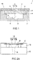
- Fig. 1 is a vertical cross-sectional view of a light-emitting device 1 according to a first embodiment.
- the light-emitting device 1 includes: a light-emitting element 20; a light-transmissive heat dissipation member 11 having a plate shape, light that is emitted from the light-emitting element 20 passing through the light-transmissive heat dissipation member 11; a wavelength conversion member 12 that includes a laminated layer of a light scattering layer 12a and a fluorescent layer 12b, takes in, from a side of the light scattering layer 12a, light that is emitted from the light-emitting element 20 and passes through the light-transmissive heat dissipation member 11, and converts a wavelength in the fluorescent layer 12b; a high-heat conduction member 13 in contact with a side surface of the wavelength conversion member 12 via a light reflection member 14; and a package 21 that houses the light-emitting element 20.
- the high-heat conduction member 13 and the light reflection member 14 constitute a lateral heat dissipation member for releasing the heat of the wavelength conversion member 12 to the lateral side, which has a plate shape and is in contact with the upper surface of the light-transmissive heat dissipation member 11.
- the light-transmissive heat dissipation member 11, the wavelength conversion member 12, the high-heat conduction member 13, and the light reflection member 14 constitute a wavelength conversion unit 100, and the wavelength conversion unit 100 is supported by the package 21.
- the light-emitting device 1 can be formed by attaching the wavelength conversion unit 100 to the opening of the package 21 in which the light-emitting element 20 and the like are housed.
- the thermal conductivity of the light-transmissive heat dissipation member 11 is favorably higher than the thermal conductivity of the wavelength conversion member 12. Further, the thermal conductivity of the high-heat conduction member 13 is favorably higher than the thermal conductivity of the light-transmissive heat dissipation member 11.
- the fluorescent layer 12b constituting the wavelength conversion member 12 is a layer containing a fluorophore that absorbs light (excitation light) emitted from the light-emitting element 20 and emits fluorescence.
- the fluorescent layer 12b is, for example, a member in which fluorophore particles are contained in a base material formed of alumina, glass, a resin, or the like, or a sintered body of a fluorophore.
- the fluorophore contained in the fluorescent layer 12b is not particularly limited.
- a yellowish fluorophore such as a YAG (yttrium ⁇ aluminum ⁇ garnet) fluorophore, an ⁇ - SiAlON fluorophore, and a BOS (barium ⁇ orthosilicate) fluorophore may be used, or these yellowish fluorophores may be mixed with a green fluorophore such as a ⁇ - SiAlON fluorophore and a red fluorophore such as (Ca,Sr) 2 Si 5 N 8 :Eu and CaAlSiN 3 :Eu and used.
- the light scattering layer 12a constituting the wavelength conversion member 12 is capable of scattering the light emitted from the light-emitting element 20 (excitation light of the fluorophore contained in the fluorescent layer 12b) before reaching the fluorescent layer 12b to reduce viewing angle dependency of the light emitted from the light-emitting device 1.
- the light scattering layer 12a contains no fluorophore.
- the fluorescent layer 12b includes a sintered body of a fluorophore
- a material obtained by removing the activator (impurity that is the center of light emission) of the fluorophore contained in the fluorescent layer 12b from the material of the fluorescent layer 12b can be used as the material of the light scattering layer 12a.
- the fluorescent layer 12b includes a sintered body of a YAG fluorophore having Ce as an activator and alumina
- a sintered body of YAG containing no Ce and alumina can be used as the material of the light scattering layer 12a.
- the wavelength conversion member 12 may be one obtained by bonding the light scattering layer 12a formed of a transparent scattering material such as alumina and the fluorescent layer 12b to each other.
- green sheets (sheets having flexibility before sintering) of the light scattering layer 12a and the fluorescent layer 12b can be sintered in a bonded state to be integrated.
- the material obtained by removing an activator from the fluorophore constituting the fluorescent layer 12b is used as the material of the light scattering layer 12a, it is possible to suppress deformation and breakage due to the difference in linear expansion coefficient because the linear expansion coefficient of the light scattering layer 12a and the fluorescent layer 12b are equal to each other.
- the activator diffuses from the fluorescent layer 12b to the light scattering layer 12a to generate concentration gradation, and the interface between the fluorescent layer 12b and the light scattering layer 12a disappears. As a result, it is possible to suppress the generation of light (return light) returning from the wavelength conversion member 12 to the side of the light-emitting element 20 due to reflection at the interface between the fluorescent layer 12b and the light scattering layer 12a.
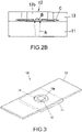
- Fig. 2A and Fig. 2B are respectively diagrams schematically showing the distribution of heat inside the wavelength conversion member 12 in the case where the wavelength conversion member 12 includes a laminate of the light scattering layer 12a and the fluorescent layer 12b and in the case where the wavelength conversion member 12 includes only the fluorescent layer 12b.
- Arrows A in Fig. 2A and Fig. 2B schematically represent the path of light emitted from the light-emitting element 20.
- a heat generation region B inside the wavelength conversion member 12 schematically represents a region in which the amount of heat generation is particularly large, of regions in which the fluorophore absorbs light and generates heat.
- arrows C schematically represent the path of heat transferred from the heat generation region B to the high-heat conduction member 13 that is a member in which the thermal conductivity is particularly high.
- the wavelength conversion member 12 includes a laminate of the light scattering layer 12a and the fluorescent layer 12b, as shown in Fig. 2A , the light that has passed through the light-transmissive heat dissipation member 11 diffuses in the light scattering layer 12a and then enters the fluorescent layer 12b. For this reason, light is absorbed in a relatively large range of the fluorescent layer 12b and the amount of heat generation per unit volume in the heat generation region B is reduced. Further, since the heat generation region B is relatively large, the distance to the high-heat conduction member 13 is small and heat can be efficiently released to the high-heat conduction member 13.
- the wavelength conversion member 12 includes only the fluorescent layer 12b, as shown in Fig. 2B , the light that has passed through the light-transmissive heat dissipation member 11 is absorbed by the fluorescent layer 12b as it is. For this reason, light is absorbed in a relatively wide range of the fluorescent layer 12b and the amount of heat generation per unit volume in the heat generation region B increases. Further, since the heat generation region B is relatively small, the distance to the high-heat conduction member 13 is large and it is difficult to efficiently release the heat to the high-heat conduction member 13.
- the wavelength conversion member 12 of a laminate of the light scattering layer 12a and the fluorescent layer 12b, it is possible to suppress the temperature rise of the fluorescent layer 12b and suppress the temperature quenching.
- the thickness of the light scattering layer 12a is favorably, for example, within a range of 50 ⁇ m or more and 200 ⁇ m or less.
- the thickness of the fluorescent layer 12b is favorably, for example, within a range of 50 ⁇ m or more and 100 ⁇ m or less.
- the planar shape of the wavelength conversion member 12 is typically a quadrangle, but may be a circle or a polygon other than the quadrangle.
- the wavelength conversion member 12 is adhered to the upper surface of the light-transmissive heat dissipation member 11 by, for example, a transparent adhesive (not shown) such as a silicone-based adhesive.
- the light-emitting element 20 functions as an excitation light source for the fluorophore contained in the fluorescent layer 12b.
- the light-emitting element 20 is mounted on the package 21 while being placed on a pedestal 23.
- the light emitted from the light-emitting element 20 is reflected by a light reflection member 22 such as a mirror and then passes through the light-transmissive heat dissipation member 11 to enter the wavelength conversion member 12.
- a light reflection member 22 such as a mirror
- the light-transmissive heat dissipation member 11 may be directly applied to the light-transmissive heat dissipation member 11 without using the light reflection member 22.
- the light-emitting device 1 may include a plurality of light-emitting elements 20 or a plurality of light reflection members 22.
- the light-emitting element 20 is an LD (laser diode) or an LED (light-emitting diode).
- the effect of suppressing the temperature rise of the fluorescent layer 12b of the light-emitting device 1 is particularly important in the case where an LD having a large output is used as the light-emitting element 20.
- the mission wavelength of the light-emitting element 20 is not particularly limited and is appropriately selected in accordance with the material (absorption wavelength) of the fluorescent layer 12b, the color of the light extracted from the light-emitting device 1, or the like.
- the material (absorption wavelength) of the fluorescent layer 12b the color of the light extracted from the light-emitting device 1, or the like.
- white light that is mixed light of the blue light extracted without being wavelength-converted in the fluorescent layer 12b and the yellow fluorescence can be extracted from the light-emitting device 1.
- the light-transmissive heat dissipation member 11 is formed of a material having a plate shape, through which light emitted from the light-emitting element 20 passes, such as sapphire. The light emitted from the light-emitting element 20 passes through the light-transmissive heat dissipation member 11 to enter the wavelength conversion member 12.
- the upper surface of the light-transmissive heat dissipation member 11 is in contact with the lower surface of the wavelength conversion member 12, and is capable of releasing the heat generated in the fluorescent layer 12b of the wavelength conversion member 12 to the light-transmissive heat dissipation member 11.
- the high-heat conduction member 13 is a member that has a plate shape and has thermal conductivity higher than that of the light-transmissive heat dissipation member 11.
- a heat dissipation sheet or a metal plate can be used as the high-heat conduction member 13.
- the metal plate for example, those formed of SUS(stainless steel), Cu, or Al can be used.
- clad materials such as CMC(Cu/Mo/Cu laminate) and a Cu/AlN/Cu laminate or impregnated carbon can be used as the material of the metal plate.
- a material having anisotropic heat conduction properties such as a graphite sheet, can be used as the high-heat conduction member 13 to improve the thermal conductivity in the in-plane direction.
- the high-heat conduction member 13 is in contact with the side surface of the wavelength conversion member 12 via the light reflection member 14 and is capable of releasing the heat generated in the fluorescent layer 12b of the wavelength conversion member 12 to the high-heat conduction member 13. Further, the high-heat conduction member 13 is also capable of releasing, further to the high-heat conduction member 13, the heat transferred from the wavelength conversion member 12 to the light-transmissive heat dissipation member 11.
- the light reflection member 14 is in contact with the side surface of the wavelength conversion member 12 and is capable of preventing light from leaking from the side surface of the wavelength conversion member 12 and improving the light extraction efficiency.
- the light reflection member 14 is formed of, for example, a material obtained by adding a reflective filler such as alumina, TiO, and BN to a base material formed of glass, a silicone resin, or the like. The higher the thermal conductivity of the light reflection member 14, the better.
- the package 21 is favorably formed of a material through which the light emitted from the light-emitting element 20 and the light that has been wavelength-converted by the wavelength conversion member 12 do not pass, which has excellent thermal conductivity, such as AlN, alumina, Si, and Si 3 N 4 .
- the package 21 is thermally bonded to the light-transmissive heat dissipation member 11 via an adhesive material 24.
- the thermally bonding means bonding with no heat-insulating layer having low thermal conductivity, such as an air layer. For this reason, the heat released from the fluorescent layer 12b of the wavelength conversion member 12 to the light-transmissive heat dissipation member 11 can be further released to the package 21.
- the adhesive material 24 is formed of, for example, solder, a sintered metal such as Ag and Cu, or glass frit, and is favorably formed of, particularly, AuSn solder having excellent thermal conductivity, solder using Cu as a base material, or the like.
- the adhesive material 25 is formed of, for example, an adhesive, an adhesive sheet, or solder, and is favorably formed of, particularly, AuSn solder having excellent thermal conductivity, solder using Cu as a base material, or the like.
- a space inside the package 21 in which the light-emitting element 20 and the light reflection member 22 are housed can be hermetically sealed by the package 21 and the wavelength conversion unit 100. This hermetically sealing makes it possible to suppress contamination of the light-emitting element 20 and the light reflection member 22 due to water and siloxane gas generated from the resin member.
- the adhesive material 24 has an annular shape and bonds the package 21 and the light-transmissive heat dissipation member 11 to each other without gaps, making it possible to hermetically sealing, by the package 21, the light-transmissive heat dissipation member 11, and the adhesive material 24, the space inside the package 21 in which the light-emitting element 20 and the light reflection member 22 are housed.
- the height of the upper surface of the wavelength conversion member 12 is favorably equal to or higher than the height of the upper surface of the high-heat conduction member 13.
- Fig. 3 is a perspective view of an example of the wavelength conversion unit 100.
- the high-heat conduction member 13 is laminated on the light-transmissive heat dissipation member 11, and the wavelength conversion member 12 is placed in a hole 13a of the high-heat conduction member 13.
- Either the high-heat conduction member 13 and the wavelength conversion member 12 may be fixed onto the light-transmissive heat dissipation member 11 first.
- a slurry material of the light reflection member 14 is poured into the space around the wavelength conversion member 12 in the hole 13a and the material is sintered to form the light reflection member 14.
- planar shape of the hole 13a is a circular shape in the example shown in Fig. 3 , but may be a rectangular shape. By making the planar shape of the hole 13a rectangular, it is possible to further improve the heat releasing performance by the high-heat conduction member 13 from the light-transmissive heat dissipation member 11 and the wavelength conversion member 12.
- Fig. 4 is a vertical cross-sectional view of a modified example of the light-emitting device 1.
- a light-transmissive heat dissipation member 15 instead of the light-transmissive heat dissipation member 11, a light-transmissive heat dissipation member 15 in which an AR (Anti-Reflection) film 15b and a DBR (Distributed Bragg Reflector) film 15c are respectively provided on the lower surface and the upper surface of a base material 15a having a plate shape (corresponding to the light-transmissive heat dissipation member 11) may be used.
- an AR Anti-Reflection
- DBR Distributed Bragg Reflector
- the AR film 15b is capable of suppressing the reflection of light emitted from the light-emitting element 20 on the lower surface of the light-transmissive heat dissipation member 15.
- the AR film 15b may be a periodic structure such as a nanoimprint.
- the DBR film 15c has a property of transmitting the light emitted from the light-emitting element 20 therethrough and reflecting the fluorescence emitted from the fluorescent layer 12b of the wavelength conversion member 12. By using the AR film 15b and the DBR film 15c, it is possible to improve the light extraction efficiency of the light-emitting device 1. Note that in the light-transmissive heat dissipation member 15, only one of the AR film 15b and the DBR film 15c may be used.
- the AR film 15b and the DBR film 15c are provided on a mirror-processed smooth surface of the base material 15a in order to fully exert the functions thereof.
- Fig. 5A , Fig. 5B, and Fig. 5C are each an enlarged view of the periphery of the wavelength conversion member 12 according to a modified example of the light-emitting device 1.
- the wavelength conversion member 12 may have a tapered shape in which part or whole on the lower side is tapered toward the lower side (the side of the light-transmissive heat dissipation member 11). That is, part or whole on the lower side of the side surface of the wavelength conversion member 12 may have an inclined surface 12c such that the width of the wavelength conversion member 12 is narrowed toward the lower side.
- the inclined surface 12c it is possible to reflect, by the inclined surface 12c, light traveling downward through the wavelength conversion member 12 to reduce the return light from the wavelength conversion member 12 to the side of the light-emitting element 20. As a result, it is possible to improve the light extraction efficiency of the light-emitting device 1. Further, by providing the inclined surface 12c, the contact area with the light reflection member 14 increases as compared with the case where the side surface is vertical, and therefore, the heat can be easily released to the high-heat conduction member 13 via the light reflection member 14.
- a light-reflecting adhesive material 16 obtained by adding a reflective filler such as TiO 2 and BN to an adhesive material such as a silicone-based adhesive material may be used to bond the inclined surface 12c of the wavelength conversion member 12 and the upper surface of the light-transmissive heat dissipation member 11 to each other.
- a light-reflecting adhesive material 16 it is possible to further reduce the return light from the wavelength conversion member 12.
- the width of the fluorescent layer 12b may be reduced to be smaller than the width of the light scattering layer 12a.
- the heat from the fluorescent layer 12b is transferred to the light scattering layer 12a while spreading, and the contact area between the light scattering layer 12a and the light-transmissive heat dissipation member 11 with respect to the area of the fluorescent layer 12b increases, improving the heat dissipation.
- the wavelength conversion member 12 is prevented from peeling of and the reliability of the light-emitting device 1 is improved.
- a light-emitting device 2 according to a second embodiment is different from the light-emitting device 1 according to the first embodiment in that the light-emitting device 2 further includes a heat dissipation member 17 described below. Note that members similar to those of the first embodiment will be denoted by the same reference symbols and description thereof will be omitted or simplified.
- Fig. 6 is a vertical cross-sectional view of the light-emitting device 2 according to the second embodiment.
- the light-emitting device 2 includes the heat dissipation member17 having a plate shape between the light-transmissive heat dissipation member 11 and the high-heat conduction member 13.
- the side surface, the upper surface, and the lower surface of the heat dissipation member 17 are respectively in contact with the side surface of the wavelength conversion member 12, the lower surface of the high-heat conduction member 13, and the upper surface of the light-transmissive heat dissipation member 11.
- the conductivity of the heat dissipation member 17 is higher than the conductivity of the light-transmissive heat dissipation member 11, and the conductivity of the high-heat conduction member 13 is higher than the conductivity of the heat dissipation member 17.
- the heat dissipation member 17 for example, alumina, aluminum nitride, copper, or aluminum can be used.
- the heat transferred from the wavelength conversion member 12 to the heat dissipation member 17 can be released to the high-heat conduction member 13.
- the light-emitting device 2 including the heat dissipation member 17 is superior in heat dissipation of the fluorescent layer 12b of the wavelength conversion member 12 as compared with the light-emitting device 1 that does not include the heat dissipation member 17. This is presumably because the heat can be directly radiated from the side surface of the wavelength conversion member 12 to the heat dissipation member 17 and therefore, the heat dissipation area increases.
- the high-heat conduction member 13, the light reflection member 14, and the heat dissipation member 17 constitute a lateral heat dissipation member for releasing the heat of the wavelength conversion member 12 to the lateral side, which has a plat shape and is in contact with the upper surface of the light-transmissive heat dissipation member 11.
- the light-transmissive heat dissipation member 11, the wavelength conversion member 12, the high-heat conduction member 13, the light reflection member 14, and the heat dissipation member 17 constitute a wavelength conversion unit 200, and the wavelength conversion unit 200 is supported by the package 21.
- the wavelength conversion unit 200 By attaching the wavelength conversion unit 200 to the opening of the package 21 in which the light-emitting element 20 and the like are housed, the light-emitting device 2 can be formed.
- the light-emitting device 2 may use the light-transmissive heat dissipation member 15 including one or both of the AR film 15b and the DBR film 15c instead of the light-transmissive heat dissipation member 11.
- Fig. 7 is a perspective view of an example of the wavelength conversion unit 200.
- the wavelength conversion member 12 is fitted into, for example, a hole of the heat dissipation member 17, which has a shape into which the wavelength conversion member 12 just fits.
- the heat dissipation member 17 is formed of ceramic, by embedding the wavelength conversion member 12 in the green sheet of the heat dissipation member 17 and sintering it, the heat dissipation member 17 surrounding the wavelength conversion member 12 can be formed.
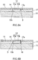
- Fig. 8A and Fig. 8B are each an enlarged view of the periphery of the wavelength conversion member 12 according to a modified example of the light-emitting device 2.
- a recessed portion 17a for providing a gap D between the heat dissipation member 17 and the side surface of the wavelength conversion member 12 may be formed in a side portion of the heat dissipation member 17 on the side of the wavelength conversion member 12. Since the refractive index of the air in the gap D is smaller than the refractive index of the wavelength conversion member 12, it is possible to improve the reflection efficiency of light on the side surface of the wavelength conversion member 12. Note that in order to cause an air layer to be adjacent to the side surface of the wavelength conversion member 12, it is required that an adhesive material (not shown) for adhering the wavelength conversion member 12 and the light-transmissive heat dissipation member 11 does not fill the gap D.
- a light reflection member 18 such as a mirror may be provided in the gap D between the wavelength conversion member 12 and the heat dissipation member 17. Since the light leaked from the side surface of the wavelength conversion member 12 to the gap D can be reflected by the light reflection member 18 toward the wavelength conversion member 12, it is possible to further improve the light extraction efficiency of the light-emitting device 2.
- the light reflection member 18 may be separated from or in contact with the wavelength conversion member 12. Further, the light reflection member 18 may be bonded to the inclined surface 12c by a bonding material or the like.
- Fig. 9A to Fig. 9C are each an enlarged view of the periphery of the wavelength conversion member 12 according to another modified example of the light-emitting device 2.
- a high-heat dissipation light reflector 19 may be provided between the wavelength conversion member 12 and the heat dissipation member 17. As a result, it is possible to improve the reflection efficiency of light on the side surface of the wavelength conversion member 12 and improve the light extraction efficiency of the light-emitting device 2. Meanwhile, since the thermal conductivity of the high-heat dissipation light reflector 19 is lower than the thermal conductivity of the heat dissipation member 17, it is possible to select whether or not to use the high-heat dissipation light reflector 19 depending on whether the light extraction efficiency of the light-emitting device 2 or the heat dissipation of the wavelength conversion member 12 is emphasized.
- the high-heat dissipation light reflector 19 is formed of, for example, a material obtained by adding a reflective filler such as TiO 2 and BN to a bonding material formed of a transparent material such as SiO 2 , glass, a silicone resin, and an epoxy resin.
- the thermal conductivity of the high-heat dissipation light reflector 19 is favorably 5 W/(m ⁇ K) or more.
- Fig. 9B is a schematic diagram showing how the wavelength conversion member 12 around which the high-heat dissipation light reflector 19 has been formed is fitted into a hole 17b of the heat dissipation member 17.
- Fig. 9C shows the state in which after fitting the wavelength conversion member 12 around which the high-heat dissipation light reflector 19 has been formed into the hole 17b of the heat dissipation member 17, the high-heat conduction member 13 and the light reflection member 14 are respectively formed on the heat dissipation member 17 and the high-heat dissipation light reflector 19.
- the high-heat dissipation light reflector 19 around which the wavelength conversion member 12 has been formed has a tapered shape that tapers toward the lower side (the side of the light-transmissive heat dissipation member 11). Further, the hole 17b of the heat dissipation member 17 has a tapered shape corresponding to the tapered shape of the high-heat dissipation light reflector 19.
- the wavelength conversion member 12 for example, by embedding the wavelength conversion member 12 in the green sheet of the high-heat dissipation light reflector 19, sintering it, and then cutting the high-heat dissipation light reflector 19 into a tapered shape, the wavelength conversion member 12 around which the high-heat dissipation light reflector 19 as shown in Fig. 9B has been formed can be formed.
- a light-emitting device 3 according to a third embodiment is different from the light-emitting device 2 according to the second embodiment in that the light-emitting device 3 has a sealing structure in which a seal member is sandwiched between a high-heat conduction member and a package. Note that members similar to those of the second embodiment will be denoted by the same reference symbols and description thereof will be omitted or simplified.
- Fig. 10 is a vertical cross-sectional view of the light-emitting device 3 according to the third embodiment.
- the high-heat conduction member 13 has a cup shape that covers the upper side and the lateral side of the package 21 and includes a fixing portion 13b for fixing to the package 21, which projects from the edge of the opening toward the outer peripheral side.
- the high-heat conduction member 13 is formed of, for example, SUS, Cu, Al, CMC (Cu/Mo/Cu laminate), Cu/AlN/Cu laminate, or impregnated carbon.
- the package 21 incudes a recessed portion 21a for housing a seal member 26 and a fixed portion 21b for fixing the high-heat conduction member 13, which projects from the vicinity of the bottom portion toward the outer peripheral side.
- the seal member 26 is, for example, an annular packing formed of a fluorine resin or the like, and exhibits the sealing function by being appropriately compressed in the thickness direction by the high-heat conduction member 13 and the package 21.
- the position of the seal member 26 is not particularly limited. As shown in Fig. 10 , the seal member 26 is favorably provided at a position in contact with the top plate (plate-shaped portion covering the upper part of the package 21) of the high-heat conduction member 13.
- the fixed portion 21b of the package 21 and the fixing portion 13b of the high-heat conduction member 13 are bonded to each other by, for example, welding, solder bonding, or caulking.
- the height of the upper surface of the wavelength conversion member 12 and the height of the upper surface of the high-heat conduction member 13 do not match in some cases due to variations in the thickness of the light-transmissive heat dissipation member 11, the heat dissipation member 17, the adhesive material 24 within the tolerance.
- the seal member 26 even in the case where the thicknesses of the light-transmissive heat dissipation member 11, the heat dissipation member 17, and the adhesive material 24 vary, it is possible to adjust the height of the upper surface of the high-heat conduction member 13 to match with the height of the upper surface of the wavelength conversion member 12. Further, by using the seal member 26, it is easy to achieve the airtightness inside the package 21 even in the case where the light-emitting device 3 has received vibration or the case where the high-heat conduction member 13 or the package 21 has received thermal stress.
- the light-emitting devices 1, 2, and 3 since the amount of heat generated by the fluorescent layer 12b can be suppressed and the heat of the fluorescent layer 12b can be effectively released by the peripheral member of the wavelength conversion member 12 such as the high-heat conduction member 13 by using the light scattering layer 12a in the wavelength conversion member 12, it is possible to effectively suppress the temperature quenching of the fluorophore contained in the fluorescent layer 12b.
- the light-emitting devices 1, 2, and 3 and the wavelength conversion units 100 and 200 included therein are applicable to, for example, a light-source apparatus, a headlight, a display apparatus, and the like.
- the relationship between the application state of laser light to the light scattering layer 12a and the temperature distribution was investigated by simulation.
- the thickness of the wavelength conversion member 12 was set to 200 ⁇ m and the thickness of the light scattering layer 12a was set to 150 ⁇ m.
- Fig. 11A shows the temperature distribution of the light scattering layer 12a in the case where laser light was uniformly applied to the surface of the light scattering layer 12a.
- Fig. 11B shows the temperature distribution of the light scattering layer 12a in the case where laser light was applied intensively to the vicinity of the center of the surface of the light scattering layer 12a.
- the temperature of a region T max whose temperature is the highest in the light scattering layer 12a in Fig. 11A was 100.9°C
- the temperature of a region T min whose temperature is the lowest was 76.8°C
- the overall average temperature was 92.0°C.
- the temperature of the region T max whose temperature is the highest in the light scattering layer 12a in Fig. 11B was 16 7.8°C
- the temperature of the region T min whose temperature is the lowest was 72.2°C
- the overall average temperature was 93.4°C.
- the thicknesses of the light scattering layer 12a and the fluorescent layer 12b, the temperature of the fluorescent layer 12b, and the brightness of light extracted from the wavelength conversion member 12 when laser light was applied to the wavelength conversion member 12 were investigated by simulation.
- the planar shape of the wavelength conversion member 12 was made a rectangular shape of 0.5 mm ⁇ 1.0 mm.
- Fig. 12A is a graph showing the relationship between the thickness of the fluorescent layer 12b when the thickness of the light scattering layer 12a was fixed to 150 ⁇ m and the thickness of the fluorescent layer 12b was changed between 0 to 250 mm and the amount of increase in the temperature of the fluorescent layer 12b from room temperature (25°C) when laser light was applied thereto.
- Fig. 12B is a graph showing the relationship between the thickness of the fluorescent layer 12b when the thickness of the light scattering layer 12a was fixed to 150 ⁇ m and the thickness of the fluorescent layer 12b was changed between 0 to 250 mm and the brightness (luminous flux) of light extracted from the wavelength conversion member 12.
- the thicker the fluorescent layer 12b the lower the temperature of the fluorescent layer 12b, but the lower the brightness of the extracted light.
- the proportion of fluorophore particles in the fluorescent layer 12b increases, and therefore, the uniformity of the fluorophore particle distribution decreases.
- the thickness of the fluorescent layer 12b is favorably 50 ⁇ m or more.
- Fig. 13A is a graph showing the relationship between the thickness of the light scattering layer 12a when the thickness of the fluorescent layer 12b was fixed to 50 ⁇ m and the thickness of the light scattering layer 12a was changed between 0 to 250 mm and the amount of increase in the temperature of the fluorescent layer 12b from room temperature (25°C) when laser light was applied thereto.
- Fig. 13B is a graph showing the relationship between the thickness of the light scattering layer 12a when the thickness of the fluorescent layer 12b was fixed to 50 ⁇ m and the thickness of the light scattering layer 12a was changed between 0 to 250 mm and the brightness (luminous flux) of light extracted from the wavelength conversion member 12.
- the thicker the light scattering layer 12a the lower the temperature of the fluorescent layer 12b, but the lower the brightness of the extracted light.
- the amount of increase in the temperature of the fluorescent layer 12b exceeds 115°C.
- the temperature of the fluorescent layer 12b exceeds 200°C, the resin forming the fluorescent layer 12b melts, and the wavelength conversion function of the fluorescent layer 12b is lost.
- the thickness of the light scattering layer 12a is favorably 50 ⁇ m or more.
- the amount of increase in the temperature of the fluorescent layer 12b is required to be substantially 100°C or less, and therefore, the thickness of the light scattering layer 12a is favorably 150 ⁇ m or more.
- the thickness of the wavelength conversion member 12 including the light scattering layer 12a and the fluorescent layer 12b is favorably the thickness capable of processing the wavelength conversion member 12 by scribe and breaking.
- the thickness of the wavelength conversion member 12 exceeds 300 ⁇ m, it becomes difficult to generate microcracks by scribe and precise processing is difficult.
- dicing needs to be used to precisely process the wavelength conversion member 12 having the thickness exceeding 300 ⁇ m, but there is a possibility that by welding the rotating dicing blade with pressure, the bonding place between the light scattering layer 12a and the fluorescent layer 12b is peeled off and chipping occurs. For this reason, the thickness of the wavelength conversion member 12 is favorably 300 ⁇ m or less.
- the thicknesses of the light scattering layer 12a and the fluorescent layer 12b are favorably such that the thickness of the wavelength conversion member 12 does not exceed 300 ⁇ m.
- the thickness of the light scattering layer 12a is favorably 200 ⁇ m or less and the thickness of the fluorescent layer 12b is favorably 100 ⁇ m or less.
- the planar shape of the wavelength conversion member 12 was made a rectangular shape of 0.5 mm ⁇ 1.0 mm and the thickness thereof was set to 200 ⁇ m.
- Fig. 14A to Fig. 14C each show the relationship between the angle of light extracted from the wavelength conversion member 12 and the chromaticity coordinate Cy of the CIE1931 chromaticity diagram.
- the angle in the direction perpendicular to the light extraction surface of the wavelength conversion member 12 is set to 0°.
- ⁇ Cy of the vertical axis in Fig. 14A to Fig. 14C represents the amount of change in the chromaticity coordinate Cy from the chromaticity coordinate Cy when the angle is 0°.
- Fig. 14A shows the properties of the wavelength conversion member 12 including only the fluorescent layer 12b.
- Fig. 14B shows the properties of the wavelength conversion member 12 including the light scattering layer 12a having the thickness of 100 ⁇ m and the fluorescent layer 12b having the thickness of 100 ⁇ m.
- Fig. 14C shows the properties of the wavelength conversion member 12 including the light scattering layer 12a having the thickness of 150 ⁇ m and the fluorescent layer 12b having the thickness of 50 ⁇ m.
- Fig. 14A to Fig. 14C each show that the angle dependency of the chromaticity is smaller as the light scattering layer 12a of the wavelength conversion member 12 is thicker.
- the application area of laser light to the fluorescent layer 12b is expanded by the scattering effect and the light distribution of laser light is closer to the Lambertian.
- the thicker the light scattering layer 12a the closer the light distribution is to the Lambertian. Therefore, the angle dependency of the chromaticity is reduced by the superposition with the fluorescence emitted from the fluorescent layer 12b having the Lambertian orientation property.
- the temperatures of the fluorescent layer 12b when laser light was applied to the wavelength conversion member 12 in the light-emitting device 1 according to the first embodiment having the configuration shown in Fig. 1 and the light-emitting device 2 according to the second embodiment having thew configuration shown in Fig. 9A were obtained and compared with each other.
- the wavelength conversion member 12 included only the fluorescent layer 12b, the planar shape thereof was made a rectangular shape of 0.5 mm ⁇ 1.0 mm, and the thickness thereof was set to 200 ⁇ m.
- the planar shape of the hole of the heat dissipation member 17 in which the wavelength conversion member 12 and the high-heat dissipation light reflector 19 are housed was made a circular shape having a diameter of 1.5 mm.
- the planar shape of the hole of the high-heat conduction member 13 in which the wavelength conversion member 12 and the light reflection member 14 are housed was made a circular shape having a diameter of 1.5 mm.
- the thermal conductivities of the light-transmissive heat dissipation member 11, the wavelength conversion member 12, the high-heat conduction member 13, the light reflection member 14, the heat dissipation member 17, and the high-heat dissipation light reflector 19 were respectively set to 25 W/(m ⁇ K), 25 W/(m ⁇ K), 85 W/(m ⁇ K), 5 W/(m ⁇ K), 16 W/(m ⁇ K), and 4 W/(m ⁇ K).
- the maximum temperature of the wavelength conversion member 12 rose from 25°C to 152.1°C by applying laser light.
- the maximum temperature of the wavelength conversion member 12 rose from 25°C to 125.3° by applying laser light.
- the temperature rise value (100.3°C) of the wavelength conversion member 12 in the light-emitting device 2 having the configuration shown in Fig. 9A with respect to the temperature rise value (127.1°C) of the wavelength conversion member 12 in the light-emitting device 1 having the configuration shown in Fig. 1 was 0.79, and it was found that the temperature rise value was reduced to 79% by using the heat dissipation member 17 and the high-heat dissipation light reflector 19.
- the following light-emitting device according to [1] to [13]
- the following light-emitting device according to [1] to [13]
- the wavelength conversion unit according to [14] to [18]
- the headlight or a display apparatus according to [19] and [20]
- a light-emitting device having a structure capable of suppressing the amount of heat generated by the wavelength conversion member and effectively releasing the heat of the wavelength conversion member to suppress the temperature quenching of the fluorophore, a wavelength conversion unit constituting the light-emitting device, and a headlight or a display apparatus including the light-emitting device or the wavelength conversion unit.
Landscapes
- Physics & Mathematics (AREA)
- General Engineering & Computer Science (AREA)
- Engineering & Computer Science (AREA)
- Optics & Photonics (AREA)
- Condensed Matter Physics & Semiconductors (AREA)
- Electromagnetism (AREA)
- General Physics & Mathematics (AREA)
- Geometry (AREA)
- Led Device Packages (AREA)
- Non-Portable Lighting Devices Or Systems Thereof (AREA)
- Optical Filters (AREA)
- Semiconductor Lasers (AREA)
- Mounting And Adjusting Of Optical Elements (AREA)
Applications Claiming Priority (2)
| Application Number | Priority Date | Filing Date | Title |
|---|---|---|---|
| JP2019177695A JP7356311B2 (ja) | 2019-09-27 | 2019-09-27 | 発光装置、波長変換ユニット、及びヘッドライト又は表示装置 |
| PCT/JP2020/036411 WO2021060519A1 (fr) | 2019-09-27 | 2020-09-25 | Dispositif électroluminescent, unité de conversion de longueur d'onde, et phare ou dispositif d'affichage |
Publications (2)
| Publication Number | Publication Date |
|---|---|
| EP4036624A1 true EP4036624A1 (fr) | 2022-08-03 |
| EP4036624A4 EP4036624A4 (fr) | 2023-05-10 |
Family
ID=75166290
Family Applications (1)
| Application Number | Title | Priority Date | Filing Date |
|---|---|---|---|
| EP20869693.0A Pending EP4036624A4 (fr) | 2019-09-27 | 2020-09-25 | Dispositif électroluminescent, unité de conversion de longueur d'onde, et phare ou dispositif d'affichage |
Country Status (4)
| Country | Link |
|---|---|
| US (1) | US20220344549A1 (fr) |
| EP (1) | EP4036624A4 (fr) |
| JP (1) | JP7356311B2 (fr) |
| WO (1) | WO2021060519A1 (fr) |
Families Citing this family (4)
| Publication number | Priority date | Publication date | Assignee | Title |
|---|---|---|---|---|
| TWI771171B (zh) * | 2021-04-16 | 2022-07-11 | 錼創顯示科技股份有限公司 | 微型發光二極體顯示面板 |
| CN217004310U (zh) * | 2022-01-12 | 2022-07-19 | 深圳市绎立锐光科技开发有限公司 | 激光光源装置及照明系统 |
| JP7538432B2 (ja) * | 2022-03-31 | 2024-08-22 | 日亜化学工業株式会社 | 光学部材及び発光装置 |
| WO2025244063A1 (fr) * | 2024-05-24 | 2025-11-27 | 京セラ株式会社 | Dispositif électroluminescent et dispositif d'éclairage |
Family Cites Families (22)
| Publication number | Priority date | Publication date | Assignee | Title |
|---|---|---|---|---|
| JP2004212522A (ja) | 2002-12-27 | 2004-07-29 | Toshiba Corp | レーザー光源モジュール装置および映像表示装置 |
| US7758224B2 (en) * | 2004-10-01 | 2010-07-20 | Nichia Corporation | Light emitting device |
| DE102006005042A1 (de) * | 2006-02-03 | 2007-08-09 | Tridonic Optoelectronics Gmbh | Licht emittierende Vorrichtung mit nicht-aktiviertem Leuchtstoff |
| EP1926154B1 (fr) * | 2006-11-21 | 2019-12-25 | Nichia Corporation | Dispositif électroluminescent semi-conducteur |
| JP6529713B2 (ja) * | 2013-09-17 | 2019-06-12 | 日亜化学工業株式会社 | 発光装置 |
| JP6398611B2 (ja) * | 2013-11-07 | 2018-10-03 | 日亜化学工業株式会社 | 発光装置及び発光装置の製造方法 |
| JP6430123B2 (ja) | 2014-02-06 | 2018-11-28 | スタンレー電気株式会社 | 波長変換体及びそれを用いた発光装置 |
| JP6225812B2 (ja) | 2014-04-18 | 2017-11-08 | 日亜化学工業株式会社 | 発光装置 |
| JP2016027613A (ja) | 2014-05-21 | 2016-02-18 | 日本電気硝子株式会社 | 波長変換部材及びそれを用いた発光装置 |
| JP6560902B2 (ja) | 2015-05-26 | 2019-08-14 | スタンレー電気株式会社 | 光源装置及びこれを用いた照明装置 |
| JP2017027019A (ja) * | 2015-07-22 | 2017-02-02 | パナソニックIpマネジメント株式会社 | 光源装置 |
| JP6560045B2 (ja) | 2015-07-29 | 2019-08-14 | 京セラ株式会社 | 発光装置 |
| US20170031118A1 (en) | 2015-07-31 | 2017-02-02 | Avago Technologies General Ip (Singapore) Pte. Ltd. | Optoelectronic components housed in a to-can package |
| WO2017043121A1 (fr) | 2015-09-10 | 2017-03-16 | シャープ株式会社 | Dispositif électroluminescent et dispositif d'éclairage |
| JP6493308B2 (ja) | 2016-05-31 | 2019-04-03 | 日亜化学工業株式会社 | 発光装置 |
| JP6862110B2 (ja) | 2016-07-04 | 2021-04-21 | 株式会社小糸製作所 | 焼結体および発光装置 |
| JP2018140725A (ja) * | 2017-02-28 | 2018-09-13 | 川崎重工業株式会社 | 舶用推進システムおよび船舶 |
| US10794569B2 (en) | 2017-03-02 | 2020-10-06 | Panasonic Intellectual Property Management Co., Ltd. | Wavelength conversion member, light source and lighting device |
| US11300788B2 (en) | 2017-10-23 | 2022-04-12 | Google Llc | Free space multiple laser diode modules |
| JP6705462B2 (ja) | 2018-01-30 | 2020-06-03 | 日亜化学工業株式会社 | 発光装置 |
| JP2019160859A (ja) | 2018-03-08 | 2019-09-19 | 豊田合成株式会社 | 発光装置 |
| US11421843B2 (en) * | 2018-12-21 | 2022-08-23 | Kyocera Sld Laser, Inc. | Fiber-delivered laser-induced dynamic light system |
-
2019
- 2019-09-27 JP JP2019177695A patent/JP7356311B2/ja active Active
-
2020
- 2020-09-25 EP EP20869693.0A patent/EP4036624A4/fr active Pending
- 2020-09-25 US US17/642,436 patent/US20220344549A1/en active Pending
- 2020-09-25 WO PCT/JP2020/036411 patent/WO2021060519A1/fr not_active Ceased
Also Published As
| Publication number | Publication date |
|---|---|
| US20220344549A1 (en) | 2022-10-27 |
| JP2021057414A (ja) | 2021-04-08 |
| WO2021060519A1 (fr) | 2021-04-01 |
| EP4036624A4 (fr) | 2023-05-10 |
| JP7356311B2 (ja) | 2023-10-04 |
Similar Documents
| Publication | Publication Date | Title |
|---|---|---|
| EP4036624A1 (fr) | Dispositif électroluminescent, unité de conversion de longueur d'onde, et phare ou dispositif d'affichage | |
| JP5482378B2 (ja) | 発光装置 | |
| EP2933884B1 (fr) | Dispositif électroluminescent | |
| JP2010272847A5 (fr) | ||
| JP6399017B2 (ja) | 発光装置 | |
| JP7011143B2 (ja) | 発光装置の製造方法 | |
| JP7235944B2 (ja) | 発光装置及び発光装置の製造方法 | |
| TW200947755A (en) | Light-emitting device and its manufacturing method | |
| JPWO2014171277A1 (ja) | 発光装置 | |
| US20150003042A1 (en) | Conversion element and illuminant | |
| JP6481559B2 (ja) | 発光装置 | |
| JP2015126209A (ja) | 発光装置 | |
| CN105280801A (zh) | 发光模块 | |
| JP2011511445A (ja) | ディスプレイを背面照明するための照明装置および同照明装置を備えたディスプレイ | |
| JP2018206819A (ja) | 発光装置及びその製造方法 | |
| US11855242B2 (en) | Light emitting device and method of manufacturing the same | |
| KR102571070B1 (ko) | 발광장치 | |
| JP2020053504A (ja) | 発光装置及びその製造方法 | |
| JP2010183035A (ja) | 発光装置 | |
| US20190277454A1 (en) | Light-emitting device | |
| US10808903B2 (en) | Light converting device with ceramic protection layer | |
| JP7054005B2 (ja) | 発光装置 | |
| JP2015011796A (ja) | 発光部材とこれを用いた投光構造体 | |
| JP2024532680A (ja) | レーザ照明デバイス | |
| US11111385B2 (en) | Silicone composition |
Legal Events
| Date | Code | Title | Description |
|---|---|---|---|
| STAA | Information on the status of an ep patent application or granted ep patent |
Free format text: STATUS: THE INTERNATIONAL PUBLICATION HAS BEEN MADE |
|
| PUAI | Public reference made under article 153(3) epc to a published international application that has entered the european phase |
Free format text: ORIGINAL CODE: 0009012 |
|
| STAA | Information on the status of an ep patent application or granted ep patent |
Free format text: STATUS: REQUEST FOR EXAMINATION WAS MADE |
|
| 17P | Request for examination filed |
Effective date: 20220311 |
|
| AK | Designated contracting states |
Kind code of ref document: A1 Designated state(s): AL AT BE BG CH CY CZ DE DK EE ES FI FR GB GR HR HU IE IS IT LI LT LU LV MC MK MT NL NO PL PT RO RS SE SI SK SM TR |
|
| DAV | Request for validation of the european patent (deleted) | ||
| DAX | Request for extension of the european patent (deleted) | ||
| A4 | Supplementary search report drawn up and despatched |
Effective date: 20230412 |
|
| RIC1 | Information provided on ipc code assigned before grant |
Ipc: H01S 5/024 20060101ALI20230404BHEP Ipc: H01S 5/02 20060101ALI20230404BHEP Ipc: F21W 103/00 20180101ALI20230404BHEP Ipc: F21W 102/00 20180101ALI20230404BHEP Ipc: F21S 45/47 20180101ALI20230404BHEP Ipc: F21S 45/10 20180101ALI20230404BHEP Ipc: F21S 43/16 20180101ALI20230404BHEP Ipc: F21S 43/13 20180101ALI20230404BHEP Ipc: F21S 41/176 20180101ALI20230404BHEP Ipc: F21S 41/16 20180101ALI20230404BHEP Ipc: G02B 5/20 20060101ALI20230404BHEP Ipc: H01L 33/64 20100101ALI20230404BHEP Ipc: H01L 33/50 20100101ALI20230404BHEP Ipc: H01L 33/00 20100101ALI20230404BHEP Ipc: F21Y 115/30 20160101ALI20230404BHEP Ipc: F21Y 115/00 20160101ALI20230404BHEP Ipc: F21V 29/502 20150101ALI20230404BHEP Ipc: G02B 7/00 20210101AFI20230404BHEP |
|
| STAA | Information on the status of an ep patent application or granted ep patent |
Free format text: STATUS: EXAMINATION IS IN PROGRESS |