EP4036592B1 - Batteriegesundheitsselbsttestprotokoll - Google Patents
Batteriegesundheitsselbsttestprotokoll Download PDFInfo
- Publication number
- EP4036592B1 EP4036592B1 EP22153197.3A EP22153197A EP4036592B1 EP 4036592 B1 EP4036592 B1 EP 4036592B1 EP 22153197 A EP22153197 A EP 22153197A EP 4036592 B1 EP4036592 B1 EP 4036592B1
- Authority
- EP
- European Patent Office
- Prior art keywords
- battery
- standby power
- controller
- refrigeration unit
- transport refrigeration
- Prior art date
- Legal status (The legal status is an assumption and is not a legal conclusion. Google has not performed a legal analysis and makes no representation as to the accuracy of the status listed.)
- Active
Links
Images
Classifications
-
- H—ELECTRICITY
- H02—GENERATION; CONVERSION OR DISTRIBUTION OF ELECTRIC POWER
- H02J—ELECTRIC POWER NETWORKS; CIRCUIT ARRANGEMENTS OR SYSTEMS FOR SUPPLYING OR DISTRIBUTING ELECTRIC POWER; SYSTEMS FOR STORING ELECTRIC ENERGY
- H02J7/00—Circuit arrangements for charging or discharging batteries or for supplying loads from batteries
- H02J7/80—Circuit arrangements for charging or discharging batteries or for supplying loads from batteries including monitoring or indicating arrangements
- H02J7/84—Control of state of health [SOH]
-
- B—PERFORMING OPERATIONS; TRANSPORTING
- B60—VEHICLES IN GENERAL
- B60H—ARRANGEMENTS OF HEATING, COOLING, VENTILATING OR OTHER AIR-TREATING DEVICES SPECIALLY ADAPTED FOR PASSENGER OR GOODS SPACES OF VEHICLES
- B60H1/00—Heating, cooling or ventilating devices
- B60H1/00357—Air-conditioning arrangements specially adapted for particular vehicles
- B60H1/00364—Air-conditioning arrangements specially adapted for particular vehicles for caravans or trailers
-
- B—PERFORMING OPERATIONS; TRANSPORTING
- B60—VEHICLES IN GENERAL
- B60H—ARRANGEMENTS OF HEATING, COOLING, VENTILATING OR OTHER AIR-TREATING DEVICES SPECIALLY ADAPTED FOR PASSENGER OR GOODS SPACES OF VEHICLES
- B60H1/00—Heating, cooling or ventilating devices
- B60H1/00421—Driving arrangements for parts of a vehicle air-conditioning
- B60H1/00428—Driving arrangements for parts of a vehicle air-conditioning electric
-
- B—PERFORMING OPERATIONS; TRANSPORTING
- B60—VEHICLES IN GENERAL
- B60H—ARRANGEMENTS OF HEATING, COOLING, VENTILATING OR OTHER AIR-TREATING DEVICES SPECIALLY ADAPTED FOR PASSENGER OR GOODS SPACES OF VEHICLES
- B60H1/00—Heating, cooling or ventilating devices
- B60H1/00642—Control systems or circuits; Control members or indication devices for heating, cooling or ventilating devices
- B60H1/00735—Control systems or circuits characterised by their input, i.e. by the detection, measurement or calculation of particular conditions, e.g. signal treatment, dynamic models
-
- B—PERFORMING OPERATIONS; TRANSPORTING
- B60—VEHICLES IN GENERAL
- B60H—ARRANGEMENTS OF HEATING, COOLING, VENTILATING OR OTHER AIR-TREATING DEVICES SPECIALLY ADAPTED FOR PASSENGER OR GOODS SPACES OF VEHICLES
- B60H1/00—Heating, cooling or ventilating devices
- B60H1/00642—Control systems or circuits; Control members or indication devices for heating, cooling or ventilating devices
- B60H1/00978—Control systems or circuits characterised by failure of detection or safety means; Diagnostic methods
-
- B—PERFORMING OPERATIONS; TRANSPORTING
- B60—VEHICLES IN GENERAL
- B60L—PROPULSION OF ELECTRICALLY-PROPELLED VEHICLES; SUPPLYING ELECTRIC POWER FOR AUXILIARY EQUIPMENT OF ELECTRICALLY-PROPELLED VEHICLES; ELECTRODYNAMIC BRAKE SYSTEMS FOR VEHICLES IN GENERAL; MAGNETIC SUSPENSION OR LEVITATION FOR VEHICLES; MONITORING OPERATING VARIABLES OF ELECTRICALLY-PROPELLED VEHICLES; ELECTRIC SAFETY DEVICES FOR ELECTRICALLY-PROPELLED VEHICLES
- B60L58/00—Methods or circuit arrangements for monitoring or controlling batteries or fuel cells, specially adapted for electric vehicles
- B60L58/10—Methods or circuit arrangements for monitoring or controlling batteries or fuel cells, specially adapted for electric vehicles for monitoring or controlling batteries
- B60L58/16—Methods or circuit arrangements for monitoring or controlling batteries or fuel cells, specially adapted for electric vehicles for monitoring or controlling batteries responding to battery ageing, e.g. to the number of charging cycles or the state of health [SoH]
-
- G—PHYSICS
- G01—MEASURING; TESTING
- G01R—MEASURING ELECTRIC VARIABLES; MEASURING MAGNETIC VARIABLES
- G01R31/00—Arrangements for testing electric properties; Arrangements for locating electric faults; Arrangements for electrical testing characterised by what is being tested not provided for elsewhere
- G01R31/36—Arrangements for testing, measuring or monitoring the electrical condition of accumulators or electric batteries, e.g. capacity or state of charge [SoC]
- G01R31/392—Determining battery ageing or deterioration, e.g. state of health
-
- H—ELECTRICITY
- H02—GENERATION; CONVERSION OR DISTRIBUTION OF ELECTRIC POWER
- H02J—ELECTRIC POWER NETWORKS; CIRCUIT ARRANGEMENTS OR SYSTEMS FOR SUPPLYING OR DISTRIBUTING ELECTRIC POWER; SYSTEMS FOR STORING ELECTRIC ENERGY
- H02J7/00—Circuit arrangements for charging or discharging batteries or for supplying loads from batteries
- H02J7/40—Circuit arrangements for charging or discharging batteries or for supplying loads from batteries characterised by the exchange of charge or discharge related data
-
- H—ELECTRICITY
- H02—GENERATION; CONVERSION OR DISTRIBUTION OF ELECTRIC POWER
- H02J—ELECTRIC POWER NETWORKS; CIRCUIT ARRANGEMENTS OR SYSTEMS FOR SUPPLYING OR DISTRIBUTING ELECTRIC POWER; SYSTEMS FOR STORING ELECTRIC ENERGY
- H02J7/00—Circuit arrangements for charging or discharging batteries or for supplying loads from batteries
- H02J7/80—Circuit arrangements for charging or discharging batteries or for supplying loads from batteries including monitoring or indicating arrangements
- H02J7/82—Control of state of charge [SOC]
-
- H—ELECTRICITY
- H02—GENERATION; CONVERSION OR DISTRIBUTION OF ELECTRIC POWER
- H02J—ELECTRIC POWER NETWORKS; CIRCUIT ARRANGEMENTS OR SYSTEMS FOR SUPPLYING OR DISTRIBUTING ELECTRIC POWER; SYSTEMS FOR STORING ELECTRIC ENERGY
- H02J7/00—Circuit arrangements for charging or discharging batteries or for supplying loads from batteries
- H02J7/90—Regulation of charging or discharging current or voltage
- H02J7/933—Regulation of charging or discharging current or voltage the cycle being controlled or terminated in response to electric parameters
-
- H—ELECTRICITY
- H02—GENERATION; CONVERSION OR DISTRIBUTION OF ELECTRIC POWER
- H02J—ELECTRIC POWER NETWORKS; CIRCUIT ARRANGEMENTS OR SYSTEMS FOR SUPPLYING OR DISTRIBUTING ELECTRIC POWER; SYSTEMS FOR STORING ELECTRIC ENERGY
- H02J3/00—Circuit arrangements for AC mains or AC distribution networks
- H02J3/28—Arrangements for balancing of the load in networks by storage of energy
- H02J3/32—Arrangements for balancing of the load in networks by storage of energy using batteries or super capacitors with converting means
Definitions
- the present disclosure relates to battery technologies, and more specifically, to a battery health self-test protocol for transport refrigeration units (TRU).
- TRU transport refrigeration units
- Truck trailers used to transport perishable and frozen goods include a refrigerated trailer pulled behind a truck cab unit.
- the refrigerated trailer which houses the perishable or frozen cargo, requires a refrigeration unit for maintaining a desired temperature environment within the interior volume of the container.
- the refrigeration unit must have sufficient refrigeration capacity to maintain the product stored within the trailer at the desired temperature over a wide range of ambient air temperatures and load conditions.
- Refrigerated trailers of this type are used to transport a wide variety of products, ranging for example from freshly picked produce to deep frozen seafood.
- Product may be loaded into the trailer unit directly from the field, such as freshly picked fruits and vegetables, or from a warehouse.
- US 2019/113578 A1 discloses a device including an acquisition unit configured to obtain a time taken for a voltage level of a battery in a charge mode to change for each of a plurality of voltage sections, and a prediction unit configured to predict a state of health of the battery based on ratio information determined by comparing the time obtained for each of the plurality of voltage sections with a reference time for each of the plurality of voltage sections.
- US 5596512 A discloses a method of determining the condition of a battery which backs up a real-time clock when a main power supply fails or is disconnected.
- WO 2020/068502 A1 discloses a TRU and power system.
- a TRU controller operably connected to a sensor and configured to execute a process to determine an AC power requirement for the TRU based on at least a return air temperature.
- a power management system is configured to direct AC power the TRU based on the AC power requirement.
- a method for performing a battery health self-test protocol includes detecting, using a controller, that a TRU is connected to standby power; and charging the battery to a known charge level during a charge cycle.
- the method also includes discharging the battery during a discharge cycle by coupling the battery to a battery test resistor; and calculating battery health assessment information for the battery.
- the standby power is provided from a power grid.
- the detection comprises detecting that the TRU is plugged into the power grid.
- the method includes recharging the battery to a full charge level.
- the method includes recharging the battery using the standby power from a power grid.
- the method includes recharging the battery using only the standby power from the power grid while a generator of the TRU is not in operation.
- the method includes providing a prompt to connect the battery to the standby power if the standby power is not detected.
- the method includes using a known charge level that is less than a fully charged state of the battery.
- the method includes charging the battery using a generator of the TRU during the charging cycle.
- the method includes receiving the battery information including an age and capacity of the battery, wherein the battery information is used to calculate the battery health assessment information.
- the method includes outputting the battery health assessment information to a display.
- a system for performing a battery health self-test protocol includes a battery coupled to a TRU, and a controller coupled to the battery.
- the controller is configured to detect the TRU is connected to standby power; and charge the battery to a known charge level during a charge cycle.
- the controller is configured to discharge the battery during a discharge cycle by coupling the battery to a battery test resistor; and calculate battery health assessment information for the battery.
- the controller is further configured to detect the TRU is connected to standby power.
- the standby power is provided from a power grid, and the detection comprises detecting that the TRU is plugged into the power grid.
- the system includes a controller that is further configured to recharge the batter to a full charge level
- the system includes recharging the battery using the standby power from a power grid.
- the system includes recharging the battery using only the standby power from the power grid while a generator of the TRU is not in operation.
- the system includes a controller that is further configured to provide a prompt to connect the battery to the standby power if the standby power is not detected.
- the system includes using a known charge level that is less than a fully charged state of the battery.
- the system includes a controller that is configured to receive the battery information including an age and capacity of the battery, wherein the battery information is used to calculate the battery health assessment information.
- the system includes a display to output the battery health assessment information.
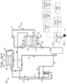
- FIG. 1 there is shown schematically, an exemplary embodiment of a truck trailer refrigeration system 100 including an engine 110, an electric generator 120 operatively associated with the engine 110, a system controller 130, a power input selector 140 and a transport refrigeration unit 10 (commonly referred to as a "TRU"). Also shown in FIG. 1 , the engine 110 is coupled to the TRU start battery 150 (hereinafter referred to as the “battery 150"), and the battery charger 160 is coupled to the controller 130 and the battery 150.
- the transport refrigeration unit 10 described herein may function to regulate and maintain a desired product storage temperature range within a refrigerated volume wherein a perishable or frozen product is stored during transport, such as a refrigerated box of a trailer.
- the transport refrigeration unit 10 may include a compressor 20, a condenser heat exchanger unit 30 including a condenser heat exchange coil 32 and associated condenser fan 34 and fan motor 36 assembly, an evaporator heat exchanger unit 40 including an evaporator heat exchanger coil 42 and associated evaporator fan 44 and fan motor 46 assembly, and an evaporator expansion device 50, such as an electronic expansion valve (EXV) or a thermostatic expansion valve (TXV), connected in a conventional refrigeration cycle by refrigerant lines 2, 4 and 6 in a refrigerant flow circuit.
- the condenser heat exchanger unit 30 may also include a subcooling coil 38 disposed in series refrigeration flow relationship with and downstream of the primary condenser heat exchange coil 32.
- the refrigeration system can also include other components that are known to be associated with refrigeration systems such as, sensors, other expansion devices, other types of heat exchangers, valves, thermostats, receivers, filter driers, etc.
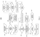
- FIG. 2 a flowchart of a method 200 for performing the battery health self-test in accordance with one or more embodiments is shown. It should be understood the method 200 can be implemented in any suitable system, such as the system 100 shown in FIG. 1 (although other suitable systems may be used to implement the method 200 in certain instances).
- the method 200 begins and proceeds to block 202 to initiate the battery health self-test (referred to herein as "self-test").
- self-test can be automatically performed according to a schedule.
- the self-test can be performed when a manual selection is provided and input to the controller 130.
- the standby power is provided from a power grid (AC power).
- the TRU may be designed to be plugged into an outlet to receive the standby power which allows the charging of the battery 150 or provide a supply of power for other operations.
- a message can be provided on a display of an interface to plug in the TRU at 206. The method 200 then returns to block 204 to determine if the TRU has been connected to the standby power.
- the method 200 proceeds to block 208 and displays a message to retrieve the battery information.
- the battery information can be retrieved automatically from one or more sources the controller 130 may have access to such as a battery/power system, a diagnostic system (e.g., onboard diagnostic system (ODB)), or another type of TRU-related system.
- the battery information can be manually input by an operator (block 210) and provided to the controller 130 and used for battery calculations.
- the battery information can include but is not limited to the battery age and capacity. It should be understood that additional information can be retrieved and input into the controller 130 to perform the self-test and is not intended to be limited by that shown in FIG. 2 .
- the method 200 continues to block 212 and starts the self-test and proceeds to block 214 which operates the TRU to charge the battery 150 (either fully or partially).
- an engine 110 that converts fuel to mechanical energy to drive a generator 120 of the TRU is used to generate power to charge the battery to a known level to perform the self-test.
- the charge level of the battery 150 is charged to a known level that is less than a fully charged level.
- the battery can be fully charged.
- the source of power for the generator 120 can include a fuel-type source such as diesel.
- the engine 110 of the TRU that drives the generator 120 is not in operation during the self-test.
- the controller 130 checks the voltage and charge time of the battery 150. If the expected voltage level and charge time are not met, the TRU continues to charge the battery to the expected level. If the voltage level and charge time are met ("Yes" branch), the method 200 proceeds to block 218 which runs a battery rest interval to settle the battery. The rest interval allows the charge level of the battery to settle at a voltage level and minimize the fluctuations in voltage resulting from charging so that an accurate test can be performed.
- the controller 130 determines whether the battery has settled during the rest interval. In a non-limiting example, the battery can be determined to be settled if the voltage level is within a margin. If not (“No" branch) the method 200 returns to block 218 to run/continue the battery rest interval.
- the method 200 continues to block 222 and runs the battery drain interval (which may be referred to as the discharge cycle).
- a known load i.e., a battery test resistor
- the battery drain interval is checked to see if it is completed. In one or more embodiments, the battery drain interval is completed responsive to reaching a predetermined or known discharge level. In other embodiments, the battery drain interval can be completed responsive to the expiration of a period of time. If the battery drain interval is not completed (“No" branch), the method 200 returns to block 222 to run/continue to battery drain interval (i.e., the discharge cycle).
- the known load is electrically disconnected from the battery 150 to stop the discharging of the battery 150 and various battery measurements can be taken.
- the method 200 proceeds to block 226 to start the recharge cycle for the battery 150 and calculate the battery health assessment information.
- the battery health assessment information can be output to a display.
- the battery recharge cycle only uses the wall power/grid power to recharge the battery 150. In these instances, the engine 110 and generator are not required to recharge the battery 150 immediately after performing the self-test.
- the controller 130 determines whether the battery 150 has been fully recharged using the standby power. If not ("No" branch), the method 200 proceeds to block 232 to continue to recharge the battery 150. If the battery 150 is fully recharged ("Yes" branch), the method 200 proceeds to block 234, and the method 200 ends. The method 200 can be repeated at a scheduled time or upon manual initiation by an operator. It should be understood that a different sequence of steps or additional steps can be used.
- the techniques described herein enable testing of the battery while the system is not in operation. Conventional systems are required to remain in operation to perform a battery health test. The battery can be tested and recharged to full capacity without operator intervention using the techniques described herein. The techniques described herein allow the batteries to be replaced on an as-needed basis as opposed to a prescribed maintenance schedule where usable life remains in the battery.
Landscapes
- Engineering & Computer Science (AREA)
- Physics & Mathematics (AREA)
- Power Engineering (AREA)
- Mechanical Engineering (AREA)
- Thermal Sciences (AREA)
- General Physics & Mathematics (AREA)
- Sustainable Energy (AREA)
- Transportation (AREA)
- Sustainable Development (AREA)
- Life Sciences & Earth Sciences (AREA)
- Charge And Discharge Circuits For Batteries Or The Like (AREA)
- Health & Medical Sciences (AREA)
- General Health & Medical Sciences (AREA)
- Medical Informatics (AREA)
Claims (15)
- Verfahren (200) zum Durchführen eines Batteriegesundheitssselbsttestprotokolls, wobei das Verfahren umfasst:Laden der Batterie (150) auf einen bekannten Ladezustand während eines Ladezyklus;Entladen der Batterie während eines Entladezyklus durch Koppeln der Batterie an einen Batterietestwiderstand; undBerechnen von Batteriegesundheitsbeurteilungsinformationen für die Batterie;dadurch gekennzeichnet, dass das Verfahren ferner ein anfängliches Erfassen unter Verwendung einer Steuerung (130), dass ein Transportkühlaggregat (10) mit Standby-Strom verbunden ist, und dass der Standby-Strom von einem Stromnetz bereitgestellt wird, umfasst, und die Erfassung ein Erfassen, dass das Transportkühlaggregat (10) an das Stromnetz angeschlossen ist, umfasst.
- Verfahren (200) nach Anspruch 1, ferner umfassend ein Wiederaufladen der Batterie (150) auf einen vollen Ladezustand.
- Verfahren nach Anspruch 2, wobei das Wiederaufladen der Batterie ein Verwenden des Standby-Stroms von dem Stromnetz umfasst.
- Verfahren nach Anspruch 3, wobei das Wiederaufladen der Batterie ein Verwenden des Standby-Stroms von dem Stromnetz nur umfasst, während ein Generator des Transportkühlaggregats nicht in Betrieb ist.
- Verfahren (200) nach einem der vorhergehenden Ansprüche, ferner umfassend ein Bereitstellen einer Aufforderung zum Verbinden der Batterie (150) mit dem Standby-Strom, wenn der Standby-Strom nicht erfasst wird.
- Verfahren nach einem der vorhergehenden Ansprüche,
wobei der bekannte Ladezustand niedriger als ein voller Ladezustand der Batterie ist; und/oder:
wobei der Ladezyklus ein Laden der Batterie unter Verwendung eines Generators des Transportkühlaggregats umfasst. - Verfahren (200) nach einem der vorhergehenden Ansprüche, ferner umfassend ein Empfangen der Batterieinformationen, umfassend Alter und Kapazität der Batterie (150), wobei die Batterieinformationen dazu verwendet werden, die Batteriegesundheitsbeurteilungsinformationen zu berechnen.
- Verfahren nach einem der vorhergehenden Ansprüche, ferner umfassend ein Ausgeben der Batteriegesundheitsbeurteilungsinformationen an eine Anzeige.
- System (100) zum Durchführen eines Batteriegesundheitsselbsttestprotokolls, wobei das System umfasst:eine Batterie (150), die an ein Transportkühlaggregat (10) gekoppelt ist; undeine Steuerung (130), die an die Batterie gekoppelt ist, wobei die Steuerung konfiguriert ist zum:Laden der Batterie auf einen bekannten Ladezustand während eines Ladezyklus;Entladen der Batterie während eines Entladezyklus durch Koppeln der Batterie an einen Batterietestwiderstand; undBerechnen von Batteriegesundheitsbeurteilungsinformationen für die Batterie;dadurch gekennzeichnet, dass die Steuerung ferner dazu konfiguriert ist, anfänglich zu erfassen, dass das Transportkühlaggregat mit Standby-Strom verbunden ist, und dass der Standby-Strom von einem Stromnetz bereitgestellt wird, und wobei die Erfassung ein Erfassen, dass das Transportkühlaggregat (10) an das Stromnetz angeschlossen ist, umfasst.
- System (100) nach Anspruch 9, wobei die Steuerung (130) ferner dazu konfiguriert ist, die Batterie (150) auf einen vollen Ladezustand wiederaufzuladen.
- System (100) nach Anspruch 10, wobei das Wiederaufladen der Batterie (150) ein Verwenden des Standby-Stroms von einem Stromnetz umfasst.
- System (100) nach Anspruch 11, wobei das Wiederaufladen der Batterie (150) ein Verwenden des Standby-Stroms von dem Stromnetz nur umfasst, während ein Generator des Transportkühlaggregats nicht in Betrieb ist.
- System (100) nach einem der Ansprüche 9-12, wobei die Steuerung (120) ferner dazu konfiguriert ist, eine Aufforderung zum Verbinden der Batterie (150) mit dem Standby-Strom, wenn der Standby-Strom nicht erfasst wird, bereitzustellen; und/oder:
wobei der bekannte Ladezustand niedriger als ein voller Ladezustand der Batterie ist; und/oder:
wobei der Ladezyklus ein Laden der Batterie unter Verwendung eines Generators des Transportkühlaggregats umfasst. - System (100) nach einem der Ansprüche 9-13, wobei die Steuerung (120) ferner dazu konfiguriert ist, die Batterieinformationen, umfassend Alter und Kapazität der Batterie (150), zu empfangen, wobei die Batterieinformationen dazu verwendet werden, die Batteriegesundheitsbeurteilungsinformationen zu berechnen.
- System nach einem der Ansprüche 9-14, ferner umfassend eine Anzeige zum Ausgeben der Batteriegesundheitsbeurteilungsinformationen.
Applications Claiming Priority (1)
| Application Number | Priority Date | Filing Date | Title |
|---|---|---|---|
| US202163141531P | 2021-01-26 | 2021-01-26 |
Publications (2)
| Publication Number | Publication Date |
|---|---|
| EP4036592A1 EP4036592A1 (de) | 2022-08-03 |
| EP4036592B1 true EP4036592B1 (de) | 2025-01-01 |
Family
ID=80034752
Family Applications (1)
| Application Number | Title | Priority Date | Filing Date |
|---|---|---|---|
| EP22153197.3A Active EP4036592B1 (de) | 2021-01-26 | 2022-01-25 | Batteriegesundheitsselbsttestprotokoll |
Country Status (3)
| Country | Link |
|---|---|
| US (1) | US12388278B2 (de) |
| EP (1) | EP4036592B1 (de) |
| CN (1) | CN114791570A (de) |
Families Citing this family (1)
| Publication number | Priority date | Publication date | Assignee | Title |
|---|---|---|---|---|
| CN120245811B (zh) * | 2025-05-21 | 2025-10-21 | 盐城特想智能机械有限公司 | 基于人工智能的新能源汽车动力电池包安全性监测系统 |
Family Cites Families (35)
| Publication number | Priority date | Publication date | Assignee | Title |
|---|---|---|---|---|
| US5596512A (en) * | 1994-08-15 | 1997-01-21 | Thermo King Corporation | Method of determining the condition of a back-up battery for a real time clock |
| US6222370B1 (en) * | 1998-03-13 | 2001-04-24 | Brian Walter Schousek | Universal battery monitor |
| JP2002323280A (ja) | 2001-04-24 | 2002-11-08 | Toshiba Kyaria Kk | 冷凍車 |
| US6622505B2 (en) * | 2001-06-08 | 2003-09-23 | Thermo King Corporation | Alternator/invertor refrigeration unit |
| US20050156603A1 (en) * | 2003-04-02 | 2005-07-21 | Hsin-An Lin | Method of testing a battery pack by purposeful charge/discharge operations |
| TWI286218B (en) * | 2006-04-27 | 2007-09-01 | Ablerex Electronics Co Ltd | Method for determining state-of-health of batteries |
| US7928735B2 (en) * | 2007-07-23 | 2011-04-19 | Yung-Sheng Huang | Battery performance monitor |
| EP2253059B2 (de) | 2008-03-14 | 2018-07-25 | Innosense AG | Elektrische lade- und/oder entladevorrichtung |
| US7983862B2 (en) * | 2008-04-22 | 2011-07-19 | GM Global Technology Operations LLC | Battery state-of-health monitoring system and method |
| US8508191B2 (en) * | 2009-07-29 | 2013-08-13 | The Regents Of The University Of Michigan | System for scheduling battery charge and discharge in a reconfigurable battery |
| TWI411796B (zh) * | 2009-12-22 | 2013-10-11 | Ind Tech Res Inst | 電池循環壽命估測裝置 |
| US8536834B2 (en) | 2010-12-23 | 2013-09-17 | Thermo King Corporation | Mobile environment-controlled unit and method of operating a mobile environment-controlled unit |
| WO2012138500A1 (en) * | 2011-04-04 | 2012-10-11 | Carrier Corporation | Transport refrigeration system and method for operating |
| US9389007B1 (en) * | 2013-01-09 | 2016-07-12 | New West Technologies, LLC | Transportation refrigeration system with integrated power generation and energy storage |
| CN103969585B (zh) | 2013-01-31 | 2018-03-30 | 国际商业机器公司 | 评估电池的使用状况的方法和装置、相关系统和车辆 |
| US9878631B2 (en) * | 2014-02-25 | 2018-01-30 | Elwha Llc | System and method for predictive control of an energy storage system for a vehicle |
| DE102014206237A1 (de) | 2014-04-02 | 2015-10-08 | Robert Bosch Gmbh | Hybrid-Antriebsstrang |
| FR3020142B1 (fr) * | 2014-04-16 | 2016-05-13 | Renault Sa | Procede d'estimation de l'etat de sante d'une batterie |
| US10026998B2 (en) * | 2014-05-15 | 2018-07-17 | Ford Global Technologies, Llc | Electric vehicle operation to manage battery capacity |
| CN106114426B (zh) | 2016-06-28 | 2019-02-15 | 广州汽车集团股份有限公司 | 一种车辆电源管理系统及其控制方法 |
| KR102441800B1 (ko) * | 2017-10-12 | 2022-09-13 | 오씨아이 주식회사 | 배터리 수명 예측 방법 및 장치 |
| KR101991241B1 (ko) | 2017-11-16 | 2019-06-20 | 써멀마스터 주식회사 | 배터리 전력 공급에 의한 차량용 냉동 시스템 |
| US20190193622A1 (en) * | 2017-12-27 | 2019-06-27 | William G Moon | Refrigerated electric truck |
| EP3536552A1 (de) * | 2018-03-06 | 2019-09-11 | Carrier Corporation | Interaktive auslösungsplanungsanwendung für eine transportkühleinheit mit einer energiespeichervorrichtung |
| US20210268864A1 (en) * | 2018-09-28 | 2021-09-02 | Carrier Corporation | Transportation refrigeration unit with cold climate battery heating |
| EP3856567A1 (de) | 2018-09-28 | 2021-08-04 | Carrier Corporation | Gleichzeitiges aufladen/entladen von batterien zur nutzung für transportkühlung |
| CN112334342B (zh) * | 2018-09-28 | 2024-11-08 | 开利公司 | 带有外部ac发电机电力来源的运输制冷单元 |
| EP3856566A1 (de) * | 2018-09-28 | 2021-08-04 | Carrier Corporation | Kühlsystem und schnittstelle für energiespeichervorrichtung |
| CN112384388B (zh) * | 2018-09-28 | 2024-07-26 | 开利公司 | 带有外部dc发电机电力来源的运输制冷单元 |
| CN111262328A (zh) | 2018-11-30 | 2020-06-09 | 厦门雅迅网络股份有限公司 | 一种车载终端备用电池管理系统 |
| US11104230B2 (en) * | 2019-01-18 | 2021-08-31 | Thermo King Corporation | Multi-source power management for a transport refrigeration system |
| ES2965029T3 (es) * | 2019-06-28 | 2024-04-10 | Thermo King Llc | Vehículo climatizado, equipo de control climático para el transporte, método de readaptación de un vehículo y método de funcionamiento |
| CN110707804B (zh) | 2019-10-18 | 2023-03-24 | 上海玫克生储能科技有限公司 | 一种具有在线测试功能的储能备电装置及测试方法 |
| CN111025168A (zh) | 2019-11-29 | 2020-04-17 | 淮南师范学院 | 一种电池健康状态监控装置及电池荷电状态智能估算方法 |
| CN111781505B (zh) * | 2020-07-13 | 2022-10-11 | 深圳市道通科技股份有限公司 | 一种车辆的检测方法、装置及检测设备 |
-
2022
- 2022-01-25 EP EP22153197.3A patent/EP4036592B1/de active Active
- 2022-01-25 CN CN202210083945.9A patent/CN114791570A/zh active Pending
- 2022-01-26 US US17/584,674 patent/US12388278B2/en active Active
Also Published As
| Publication number | Publication date |
|---|---|
| US20220239110A1 (en) | 2022-07-28 |
| EP4036592A1 (de) | 2022-08-03 |
| US12388278B2 (en) | 2025-08-12 |
| CN114791570A (zh) | 2022-07-26 |
Similar Documents
| Publication | Publication Date | Title |
|---|---|---|
| CN109562703B (zh) | 电池寿命预测及监测 | |
| CA2974750C (en) | Mobile hybrid electric refrigeration system | |
| US11085679B2 (en) | Low charge detection system for cooling systems | |
| CN101600917B (zh) | 操作具有远程蒸发器的运输制冷单元的方法 | |
| EP3377830B1 (de) | Verfahren zur erkennung des verlustes einer kältemittelfüllung in einem kühlsystem | |
| EP2938518B1 (de) | Offsetstromeinbeziehung für batterielader | |
| WO2013077992A1 (en) | Method for in-service testing a climate control system for a container | |
| EP4036592B1 (de) | Batteriegesundheitsselbsttestprotokoll | |
| EP4238787A1 (de) | Vorreisesequenz für eine brennstoffzelle für eine anhängerkühleinheit | |
| WO2020001508A1 (zh) | 一种用于储能单元充冷的控制方法及充冷装置 | |
| EP3819142A1 (de) | Leistungs- und fehlerverwaltung von elektrischen komponenten eines von einem elektrofahrzeug gespeisten transportklimatisierungssystems | |
| US20180031291A1 (en) | Vfd control for multiple circuit refrigeration system | |
| EP3663633B1 (de) | Systeme und verfahren zur steuerung des gasdurchflusses in transportkälteanlagen | |
| EP4159996B1 (de) | Verfahren und systeme zur überwachung der kraftstoffqualität und dienstleistungsprobleme für ein im transport verwendetes stromversorgungssystem | |
| CN115107467A (zh) | 用于向多个运输制冷单元供电的电架构 | |
| JP2009277366A (ja) | 鉛蓄電池の電解液残量監視装置 | |
| US10228172B2 (en) | Refrigerant level monitor for refrigeration system | |
| KR20220043414A (ko) | 차량 탑재형 냉각시스템의 가동시간 추정 장치 | |
| WO2019239836A1 (ja) | 検査システム、情報処理機器 | |
| CN114074528B (zh) | 运输气候控制系统的闭环反馈控制和诊断 |
Legal Events
| Date | Code | Title | Description |
|---|---|---|---|
| PUAI | Public reference made under article 153(3) epc to a published international application that has entered the european phase |
Free format text: ORIGINAL CODE: 0009012 |
|
| STAA | Information on the status of an ep patent application or granted ep patent |
Free format text: STATUS: THE APPLICATION HAS BEEN PUBLISHED |
|
| AK | Designated contracting states |
Kind code of ref document: A1 Designated state(s): AL AT BE BG CH CY CZ DE DK EE ES FI FR GB GR HR HU IE IS IT LI LT LU LV MC MK MT NL NO PL PT RO RS SE SI SK SM TR |
|
| STAA | Information on the status of an ep patent application or granted ep patent |
Free format text: STATUS: REQUEST FOR EXAMINATION WAS MADE |
|
| 17P | Request for examination filed |
Effective date: 20230201 |
|
| RBV | Designated contracting states (corrected) |
Designated state(s): AL AT BE BG CH CY CZ DE DK EE ES FI FR GB GR HR HU IE IS IT LI LT LU LV MC MK MT NL NO PL PT RO RS SE SI SK SM TR |
|
| P01 | Opt-out of the competence of the unified patent court (upc) registered |
Effective date: 20230527 |
|
| GRAP | Despatch of communication of intention to grant a patent |
Free format text: ORIGINAL CODE: EPIDOSNIGR1 |
|
| STAA | Information on the status of an ep patent application or granted ep patent |
Free format text: STATUS: GRANT OF PATENT IS INTENDED |
|
| RIC1 | Information provided on ipc code assigned before grant |
Ipc: B60H 1/00 20060101ALI20240630BHEP Ipc: B60P 3/20 20060101ALI20240630BHEP Ipc: B60H 1/32 20060101ALI20240630BHEP Ipc: G01R 31/392 20190101AFI20240630BHEP |
|
| INTG | Intention to grant announced |
Effective date: 20240730 |
|
| GRAS | Grant fee paid |
Free format text: ORIGINAL CODE: EPIDOSNIGR3 |
|
| GRAA | (expected) grant |
Free format text: ORIGINAL CODE: 0009210 |
|
| STAA | Information on the status of an ep patent application or granted ep patent |
Free format text: STATUS: THE PATENT HAS BEEN GRANTED |
|
| AK | Designated contracting states |
Kind code of ref document: B1 Designated state(s): AL AT BE BG CH CY CZ DE DK EE ES FI FR GB GR HR HU IE IS IT LI LT LU LV MC MK MT NL NO PL PT RO RS SE SI SK SM TR |
|
| REG | Reference to a national code |
Ref country code: GB Ref legal event code: FG4D |
|
| REG | Reference to a national code |
Ref country code: CH Ref legal event code: EP |
|
| REG | Reference to a national code |
Ref country code: DE Ref legal event code: R096 Ref document number: 602022009196 Country of ref document: DE |
|
| REG | Reference to a national code |
Ref country code: NL Ref legal event code: FP |
|
| REG | Reference to a national code |
Ref country code: IE Ref legal event code: FG4D |
|
| PGFP | Annual fee paid to national office [announced via postgrant information from national office to epo] |
Ref country code: NL Payment date: 20250219 Year of fee payment: 4 |
|
| PGFP | Annual fee paid to national office [announced via postgrant information from national office to epo] |
Ref country code: DE Payment date: 20241218 Year of fee payment: 4 |
|
| PGFP | Annual fee paid to national office [announced via postgrant information from national office to epo] |
Ref country code: AT Payment date: 20250417 Year of fee payment: 4 |
|
| REG | Reference to a national code |
Ref country code: LT Ref legal event code: MG9D |
|
| REG | Reference to a national code |
Ref country code: AT Ref legal event code: MK05 Ref document number: 1756771 Country of ref document: AT Kind code of ref document: T Effective date: 20250101 |
|
| PG25 | Lapsed in a contracting state [announced via postgrant information from national office to epo] |
Ref country code: FI Free format text: LAPSE BECAUSE OF FAILURE TO SUBMIT A TRANSLATION OF THE DESCRIPTION OR TO PAY THE FEE WITHIN THE PRESCRIBED TIME-LIMIT Effective date: 20250101 |
|
| PG25 | Lapsed in a contracting state [announced via postgrant information from national office to epo] |
Ref country code: PL Free format text: LAPSE BECAUSE OF FAILURE TO SUBMIT A TRANSLATION OF THE DESCRIPTION OR TO PAY THE FEE WITHIN THE PRESCRIBED TIME-LIMIT Effective date: 20250101 |
|
| PG25 | Lapsed in a contracting state [announced via postgrant information from national office to epo] |
Ref country code: ES Free format text: LAPSE BECAUSE OF FAILURE TO SUBMIT A TRANSLATION OF THE DESCRIPTION OR TO PAY THE FEE WITHIN THE PRESCRIBED TIME-LIMIT Effective date: 20250101 |
|
| PG25 | Lapsed in a contracting state [announced via postgrant information from national office to epo] |
Ref country code: NO Free format text: LAPSE BECAUSE OF FAILURE TO SUBMIT A TRANSLATION OF THE DESCRIPTION OR TO PAY THE FEE WITHIN THE PRESCRIBED TIME-LIMIT Effective date: 20250401 Ref country code: IS Free format text: LAPSE BECAUSE OF FAILURE TO SUBMIT A TRANSLATION OF THE DESCRIPTION OR TO PAY THE FEE WITHIN THE PRESCRIBED TIME-LIMIT Effective date: 20250501 |
|
| PG25 | Lapsed in a contracting state [announced via postgrant information from national office to epo] |
Ref country code: HR Free format text: LAPSE BECAUSE OF FAILURE TO SUBMIT A TRANSLATION OF THE DESCRIPTION OR TO PAY THE FEE WITHIN THE PRESCRIBED TIME-LIMIT Effective date: 20250101 |
|
| PG25 | Lapsed in a contracting state [announced via postgrant information from national office to epo] |
Ref country code: LV Free format text: LAPSE BECAUSE OF FAILURE TO SUBMIT A TRANSLATION OF THE DESCRIPTION OR TO PAY THE FEE WITHIN THE PRESCRIBED TIME-LIMIT Effective date: 20250101 Ref country code: PT Free format text: LAPSE BECAUSE OF FAILURE TO SUBMIT A TRANSLATION OF THE DESCRIPTION OR TO PAY THE FEE WITHIN THE PRESCRIBED TIME-LIMIT Effective date: 20250502 |
|
| PG25 | Lapsed in a contracting state [announced via postgrant information from national office to epo] |
Ref country code: BG Free format text: LAPSE BECAUSE OF FAILURE TO SUBMIT A TRANSLATION OF THE DESCRIPTION OR TO PAY THE FEE WITHIN THE PRESCRIBED TIME-LIMIT Effective date: 20250101 Ref country code: GR Free format text: LAPSE BECAUSE OF FAILURE TO SUBMIT A TRANSLATION OF THE DESCRIPTION OR TO PAY THE FEE WITHIN THE PRESCRIBED TIME-LIMIT Effective date: 20250402 |
|
| PG25 | Lapsed in a contracting state [announced via postgrant information from national office to epo] |
Ref country code: AT Free format text: LAPSE BECAUSE OF FAILURE TO SUBMIT A TRANSLATION OF THE DESCRIPTION OR TO PAY THE FEE WITHIN THE PRESCRIBED TIME-LIMIT Effective date: 20250101 |
|
| PG25 | Lapsed in a contracting state [announced via postgrant information from national office to epo] |
Ref country code: CZ Free format text: LAPSE BECAUSE OF FAILURE TO SUBMIT A TRANSLATION OF THE DESCRIPTION OR TO PAY THE FEE WITHIN THE PRESCRIBED TIME-LIMIT Effective date: 20250101 |
|
| REG | Reference to a national code |
Ref country code: CH Ref legal event code: PL |
|
| PG25 | Lapsed in a contracting state [announced via postgrant information from national office to epo] |
Ref country code: SE Free format text: LAPSE BECAUSE OF FAILURE TO SUBMIT A TRANSLATION OF THE DESCRIPTION OR TO PAY THE FEE WITHIN THE PRESCRIBED TIME-LIMIT Effective date: 20250101 |
|
| PG25 | Lapsed in a contracting state [announced via postgrant information from national office to epo] |
Ref country code: LU Free format text: LAPSE BECAUSE OF NON-PAYMENT OF DUE FEES Effective date: 20250125 |
|
| REG | Reference to a national code |
Ref country code: DE Ref legal event code: R097 Ref document number: 602022009196 Country of ref document: DE |
|
| PG25 | Lapsed in a contracting state [announced via postgrant information from national office to epo] |
Ref country code: SM Free format text: LAPSE BECAUSE OF FAILURE TO SUBMIT A TRANSLATION OF THE DESCRIPTION OR TO PAY THE FEE WITHIN THE PRESCRIBED TIME-LIMIT Effective date: 20250101 |
|
| PG25 | Lapsed in a contracting state [announced via postgrant information from national office to epo] |
Ref country code: DK Free format text: LAPSE BECAUSE OF FAILURE TO SUBMIT A TRANSLATION OF THE DESCRIPTION OR TO PAY THE FEE WITHIN THE PRESCRIBED TIME-LIMIT Effective date: 20250101 |
|
| PG25 | Lapsed in a contracting state [announced via postgrant information from national office to epo] |
Ref country code: MC Free format text: LAPSE BECAUSE OF FAILURE TO SUBMIT A TRANSLATION OF THE DESCRIPTION OR TO PAY THE FEE WITHIN THE PRESCRIBED TIME-LIMIT Effective date: 20250101 |
|
| PG25 | Lapsed in a contracting state [announced via postgrant information from national office to epo] |
Ref country code: IT Free format text: LAPSE BECAUSE OF FAILURE TO SUBMIT A TRANSLATION OF THE DESCRIPTION OR TO PAY THE FEE WITHIN THE PRESCRIBED TIME-LIMIT Effective date: 20250101 |
|
| PG25 | Lapsed in a contracting state [announced via postgrant information from national office to epo] |
Ref country code: BE Free format text: LAPSE BECAUSE OF NON-PAYMENT OF DUE FEES Effective date: 20250131 |
|
| PG25 | Lapsed in a contracting state [announced via postgrant information from national office to epo] |
Ref country code: CH Free format text: LAPSE BECAUSE OF NON-PAYMENT OF DUE FEES Effective date: 20250131 |
|
| PG25 | Lapsed in a contracting state [announced via postgrant information from national office to epo] |
Ref country code: EE Free format text: LAPSE BECAUSE OF FAILURE TO SUBMIT A TRANSLATION OF THE DESCRIPTION OR TO PAY THE FEE WITHIN THE PRESCRIBED TIME-LIMIT Effective date: 20250101 |
|
| REG | Reference to a national code |
Ref country code: BE Ref legal event code: MM Effective date: 20250131 |
|
| PG25 | Lapsed in a contracting state [announced via postgrant information from national office to epo] |
Ref country code: RO Free format text: LAPSE BECAUSE OF FAILURE TO SUBMIT A TRANSLATION OF THE DESCRIPTION OR TO PAY THE FEE WITHIN THE PRESCRIBED TIME-LIMIT Effective date: 20250101 |
|
| PG25 | Lapsed in a contracting state [announced via postgrant information from national office to epo] |
Ref country code: SK Free format text: LAPSE BECAUSE OF FAILURE TO SUBMIT A TRANSLATION OF THE DESCRIPTION OR TO PAY THE FEE WITHIN THE PRESCRIBED TIME-LIMIT Effective date: 20250101 |
|
| PLBE | No opposition filed within time limit |
Free format text: ORIGINAL CODE: 0009261 |
|
| STAA | Information on the status of an ep patent application or granted ep patent |
Free format text: STATUS: NO OPPOSITION FILED WITHIN TIME LIMIT |
|
| 26N | No opposition filed |
Effective date: 20251002 |
|
| PGFP | Annual fee paid to national office [announced via postgrant information from national office to epo] |
Ref country code: GB Payment date: 20251220 Year of fee payment: 5 |
|
| PGFP | Annual fee paid to national office [announced via postgrant information from national office to epo] |
Ref country code: FR Payment date: 20251217 Year of fee payment: 5 |
|
| PG25 | Lapsed in a contracting state [announced via postgrant information from national office to epo] |
Ref country code: IE Free format text: LAPSE BECAUSE OF NON-PAYMENT OF DUE FEES Effective date: 20250125 |