EP4036065B1 - Wasserreiniger - Google Patents
Wasserreiniger Download PDFInfo
- Publication number
- EP4036065B1 EP4036065B1 EP20868627.9A EP20868627A EP4036065B1 EP 4036065 B1 EP4036065 B1 EP 4036065B1 EP 20868627 A EP20868627 A EP 20868627A EP 4036065 B1 EP4036065 B1 EP 4036065B1
- Authority
- EP
- European Patent Office
- Prior art keywords
- flow path
- water
- reverse osmosis
- osmosis membrane
- valve
- Prior art date
- Legal status (The legal status is an assumption and is not a legal conclusion. Google has not performed a legal analysis and makes no representation as to the accuracy of the status listed.)
- Active
Links
Images


Classifications
-
- B—PERFORMING OPERATIONS; TRANSPORTING
- B01—PHYSICAL OR CHEMICAL PROCESSES OR APPARATUS IN GENERAL
- B01D—SEPARATION
- B01D35/00—Filtering devices having features not specifically covered by groups B01D24/00 - B01D33/00, or for applications not specifically covered by groups B01D24/00 - B01D33/00; Auxiliary devices for filtration; Filter housing constructions
- B01D35/14—Safety devices specially adapted for filtration; Devices for indicating clogging
- B01D35/153—Anti-leakage or anti-return valves
-
- B—PERFORMING OPERATIONS; TRANSPORTING
- B01—PHYSICAL OR CHEMICAL PROCESSES OR APPARATUS IN GENERAL
- B01D—SEPARATION
- B01D35/00—Filtering devices having features not specifically covered by groups B01D24/00 - B01D33/00, or for applications not specifically covered by groups B01D24/00 - B01D33/00; Auxiliary devices for filtration; Filter housing constructions
- B01D35/14—Safety devices specially adapted for filtration; Devices for indicating clogging
- B01D35/157—Flow control valves: Damping or calibrated passages
- B01D35/1573—Flow control valves
-
- B—PERFORMING OPERATIONS; TRANSPORTING
- B01—PHYSICAL OR CHEMICAL PROCESSES OR APPARATUS IN GENERAL
- B01D—SEPARATION
- B01D61/00—Processes of separation using semi-permeable membranes, e.g. dialysis, osmosis or ultrafiltration; Apparatus, accessories or auxiliary operations specially adapted therefor
- B01D61/002—Forward osmosis or direct osmosis
-
- B—PERFORMING OPERATIONS; TRANSPORTING
- B01—PHYSICAL OR CHEMICAL PROCESSES OR APPARATUS IN GENERAL
- B01D—SEPARATION
- B01D61/00—Processes of separation using semi-permeable membranes, e.g. dialysis, osmosis or ultrafiltration; Apparatus, accessories or auxiliary operations specially adapted therefor
- B01D61/02—Reverse osmosis; Hyperfiltration ; Nanofiltration
- B01D61/025—Reverse osmosis; Hyperfiltration
-
- B—PERFORMING OPERATIONS; TRANSPORTING
- B01—PHYSICAL OR CHEMICAL PROCESSES OR APPARATUS IN GENERAL
- B01D—SEPARATION
- B01D61/00—Processes of separation using semi-permeable membranes, e.g. dialysis, osmosis or ultrafiltration; Apparatus, accessories or auxiliary operations specially adapted therefor
- B01D61/02—Reverse osmosis; Hyperfiltration ; Nanofiltration
- B01D61/12—Controlling or regulating
-
- B—PERFORMING OPERATIONS; TRANSPORTING
- B01—PHYSICAL OR CHEMICAL PROCESSES OR APPARATUS IN GENERAL
- B01D—SEPARATION
- B01D63/00—Apparatus in general for separation processes using semi-permeable membranes
- B01D63/08—Flat membrane modules
-
- B—PERFORMING OPERATIONS; TRANSPORTING
- B01—PHYSICAL OR CHEMICAL PROCESSES OR APPARATUS IN GENERAL
- B01D—SEPARATION
- B01D65/00—Accessories or auxiliary operations, in general, for separation processes or apparatus using semi-permeable membranes
- B01D65/02—Membrane cleaning or sterilisation ; Membrane regeneration
-
- C—CHEMISTRY; METALLURGY
- C02—TREATMENT OF WATER, WASTE WATER, SEWAGE, OR SLUDGE
- C02F—TREATMENT OF WATER, WASTE WATER, SEWAGE, OR SLUDGE
- C02F1/00—Treatment of water, waste water, or sewage
- C02F1/001—Processes for the treatment of water whereby the filtration technique is of importance
-
- C—CHEMISTRY; METALLURGY
- C02—TREATMENT OF WATER, WASTE WATER, SEWAGE, OR SLUDGE
- C02F—TREATMENT OF WATER, WASTE WATER, SEWAGE, OR SLUDGE
- C02F1/00—Treatment of water, waste water, or sewage
- C02F1/001—Processes for the treatment of water whereby the filtration technique is of importance
- C02F1/003—Processes for the treatment of water whereby the filtration technique is of importance using household-type filters for producing potable water, e.g. pitchers, bottles, faucet mounted devices
-
- C—CHEMISTRY; METALLURGY
- C02—TREATMENT OF WATER, WASTE WATER, SEWAGE, OR SLUDGE
- C02F—TREATMENT OF WATER, WASTE WATER, SEWAGE, OR SLUDGE
- C02F1/00—Treatment of water, waste water, or sewage
- C02F1/44—Treatment of water, waste water, or sewage by dialysis, osmosis or reverse osmosis
- C02F1/441—Treatment of water, waste water, or sewage by dialysis, osmosis or reverse osmosis by reverse osmosis
-
- B—PERFORMING OPERATIONS; TRANSPORTING
- B01—PHYSICAL OR CHEMICAL PROCESSES OR APPARATUS IN GENERAL
- B01D—SEPARATION
- B01D2313/00—Details relating to membrane modules or apparatus
- B01D2313/12—Specific discharge elements
-
- B—PERFORMING OPERATIONS; TRANSPORTING
- B01—PHYSICAL OR CHEMICAL PROCESSES OR APPARATUS IN GENERAL
- B01D—SEPARATION
- B01D2313/00—Details relating to membrane modules or apparatus
- B01D2313/18—Specific valves
-
- C—CHEMISTRY; METALLURGY
- C02—TREATMENT OF WATER, WASTE WATER, SEWAGE, OR SLUDGE
- C02F—TREATMENT OF WATER, WASTE WATER, SEWAGE, OR SLUDGE
- C02F1/00—Treatment of water, waste water, or sewage
- C02F1/28—Treatment of water, waste water, or sewage by sorption
- C02F1/283—Treatment of water, waste water, or sewage by sorption using coal, charred products, or inorganic mixtures containing them
-
- C—CHEMISTRY; METALLURGY
- C02—TREATMENT OF WATER, WASTE WATER, SEWAGE, OR SLUDGE
- C02F—TREATMENT OF WATER, WASTE WATER, SEWAGE, OR SLUDGE
- C02F2201/00—Apparatus for treatment of water, waste water or sewage
- C02F2201/002—Construction details of the apparatus
- C02F2201/004—Seals, connections
-
- C—CHEMISTRY; METALLURGY
- C02—TREATMENT OF WATER, WASTE WATER, SEWAGE, OR SLUDGE
- C02F—TREATMENT OF WATER, WASTE WATER, SEWAGE, OR SLUDGE
- C02F2201/00—Apparatus for treatment of water, waste water or sewage
- C02F2201/002—Construction details of the apparatus
- C02F2201/005—Valves
-
- C—CHEMISTRY; METALLURGY
- C02—TREATMENT OF WATER, WASTE WATER, SEWAGE, OR SLUDGE
- C02F—TREATMENT OF WATER, WASTE WATER, SEWAGE, OR SLUDGE
- C02F2209/00—Controlling or monitoring parameters in water treatment
- C02F2209/40—Liquid flow rate
-
- C—CHEMISTRY; METALLURGY
- C02—TREATMENT OF WATER, WASTE WATER, SEWAGE, OR SLUDGE
- C02F—TREATMENT OF WATER, WASTE WATER, SEWAGE, OR SLUDGE
- C02F2303/00—Specific treatment goals
- C02F2303/22—Eliminating or preventing deposits, scale removal, scale prevention
-
- C—CHEMISTRY; METALLURGY
- C02—TREATMENT OF WATER, WASTE WATER, SEWAGE, OR SLUDGE
- C02F—TREATMENT OF WATER, WASTE WATER, SEWAGE, OR SLUDGE
- C02F2307/00—Location of water treatment or water treatment device
- C02F2307/10—Location of water treatment or water treatment device as part of a potable water dispenser, e.g. for use in homes or offices
Definitions
- the present invention relates to a water purifier including a reverse osmosis membrane filter, and more particularly, a water purifier based on reverse osmosis which may discharge residual water remaining in an extraction unit.
- a water purifier may be a device for supplying drinking water to a user by filtering water flowing in through one or more filters and discharging the water externally.
- Such a water purifier may provide purified water to a user through an extraction unit including a cock or a faucet.
- contaminated residual water may contaminate an internal portion of the extraction unit, and also, as residual water may be extracted together with purified water newly supplied as the extraction unit is opened, purified water containing the contaminated residual water may be provided to a user, which may be problematic.
- Exemplary prior art references are KR2015-0104377 A and KR2016-0142478 A .
- WO 2017/002022 A1 discloses a seawater desalination plant comprising a reverse osmosis filter.
- a rear end of the reverse osmosis filter is connected to a storage via a supply line so that water filtered by the reverse osmosis filter is supplied to the storage via the supply line.
- the reverse osmosis filter is also coupled to a discharge port via a discharge line to discharge concentrated water not filtered by the reverse osmosis filter.
- the present invention has been derived to address at least a portion of problems of the prior art as above, and the purpose of the present invention is to provide a water purifier which may stably discharge residual water in an extraction unit.
- an object of the present invention is to provide a water purifier which may naturally discharge residual water in an extraction unit without using a power source by switching a flow path through a valve when extraction is finished.
- the present invention provides a water purifier in accordance with claim 1.
- the present invention provides a water purifier including a filter unit including a reverse osmosis membrane filter configured to filter incoming water; an extraction unit configured to provide purified water filtered by the filter unit to a user; and a residual water drainage unit configured to, after extraction through the extraction unit is finished, drain residual water remaining in the extraction unit through the reverse osmosis membrane filter using an osmotic phenomenon of the reverse osmosis membrane filter.
- a purified water discharge flow path through which purified water filtered by the reverse osmosis membrane filter is discharged, and a drainage flow path through which concentrated water not filtered by the reverse osmosis membrane filter is discharged are connected to a rear end of the reverse osmosis membrane filter, the residual water drainage unit includes a residual water drainage flow path connecting the extraction unit to the purified water discharge flow path, and the residual water in the extraction unit flows into the reverse osmosis membrane filter through the residual water drainage flow path and the purified water discharge flow path by an osmosis phenomenon of the reverse osmosis membrane filter, and is drained through the drainage flow path.
- the extraction unit is connected to an extraction valve for extracting purified water, and the residual water drainage flow path connects the extraction valve to the purified water discharge flow path.
- the extraction valve is configured to operate to connect the extraction unit to the residual water drainage flow path when the residual water is drained.
- the residual water drainage unit may further include a residual water drainage valve installed in the residual water drainage flow path and opened during an operation of draining the residual water.
- the residual water drainage valve may be configured to be opened for a predetermined operation time to discharge the residual water.
- the residual water drainage valve may be configured to open after a predetermined standby time is elapsed after extraction of the extraction unit is finished.
- the residual water drainage unit may further include a non-return valve installed in the residual water drainage flow path and configured to prevent backflow of water from the purified water discharge flow path in a direction of the extraction unit.
- the drainage flow path may include a concentrated water flow path through which concentrated water not filtered by the reverse osmosis membrane filter is discharged, and a flushing flow path for flushing the reverse osmosis membrane filter, and a flushing valve configured to open the flushing flow path when the reverse osmosis membrane filter is flushed may be installed in the flushing flow path.
- the flushing valve may be configured to be open when the residual water is drained.
- an effect of stably discharging residual water from an extraction unit using an osmosis phenomenon of a reverse osmosis membrane filter may be obtained.
- an effect in which, by using an osmosis phenomenon of a reverse osmosis membrane filter, residual water in an extraction unit may be discharged naturally without using a power source by switching a flow path through a valve when extraction is finished may be obtained.
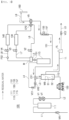
- FIG. 1 is a water-pipe diagram of a water purifier 100 according to an embodiment of the present invention
- FIG. 2 is a water-pipe diagram illustrating a water flow in extraction of purified water of the water purifier 100 illustrated in FIG. 1
- FIG. 3 is a water-pipe diagram illustrating a water flow in a case of draining residual water in an extraction unit 160 in the water purifier 100 illustrated in FIG. 1
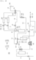
- FIG. 4 is a water-pipe diagram illustrating a water purifier 100 according to another embodiment of the present invention
- FIG. 5 is a water-pipe diagram illustrating a water flow in extraction of purified water of the water purifier 100 illustrated in FIG. 4
- FIG. 6 is a water-pipe diagram illustrating a water flow in a case of draining residual water of an extraction unit 160 in the water purifier 100 illustrated in FIG. 4 .
- the water purifier 100 includes a filter unit 110, an extraction unit 160, and a residual water drainage unit 150, and may further include a pressurization unit 120, a cold water generation unit 130, a hot water generation unit 140, and a plurality of flow paths and valves connected thereto.
- the filter unit 110 includes at least one filter including a reverse osmosis membrane filter 113 to filter incoming water and to generate purified water.
- the filter unit 110 may include three filters including a pre-treatment filter 111, a reverse osmosis membrane filter 113, and a post-treatment filter 115.
- the pre-treatment filter 111 may be configured as a composite filter of a sediment filter and a pre-carbon filter, for example, and the post-treatment filter 115 may be configured as a post-carbon filter, for example.
- the type and number of filters included in the pre-treatment filter 111 and the post-treatment filter 115 are not limited thereto.
- the reverse osmosis membrane filter 113 may filter water flowing in through the pre-treatment filter 111 as illustrated in FIGS. 1 to 6 .
- a reverse osmosis membrane MB configured as a semi-permeable membrane may be provided in the reverse osmosis membrane filter 113 and may partition an internal space of the reverse osmosis membrane filter 113 into a filtration side S1 and a non-filtration side S2.
- the reverse osmosis membrane filter 113 is configured to purify water using a reverse osmosis phenomenon (the opposite to an osmosis phenomenon) in which water may move from the non-filtration side S2 of high concentration to the filtration side S1 of low concentration by applying pressure higher than osmotic pressure to the reverse osmosis membrane MB.
- a reverse osmosis phenomenon the opposite to an osmosis phenomenon
- the water flowing into the reverse osmosis membrane filter 113 is filtered while moving in a direction from the non-filtration side S2 to the filtration side S1, and purified water which has passed through the reverse osmosis membrane MB may be accommodated in the filtration side S1, and water (concentrated water) including foreign substances in high concentration is accommodated in the non-filtration side S2 as the water has not been able to pass through the reverse osmosis membrane MB.
- a purified water discharge flow path L3 (third flow path) through which purified water filtered by the reverse osmosis membrane filter 113 is discharged is connected to the filtration side S1 of the reverse osmosis membrane filter 113, and a drainage flow path LD through which concentrated water not filtered by the reverse osmosis membrane filter 113 is discharged is connected to the non-filtration side S2 of the reverse osmosis membrane filter 113.
- the drainage flow path LD will be described later.
- the number and types of filters provided in the filter unit 110 are not limited to the aforementioned embodiment.
- an antibacterial filter or various functional filters may be added.
- a plurality of flow paths may be formed in the water purifier 100 including the filter unit 110 to filter water and to install various components.
- raw water may be supplied to the pre-treatment filter 111 through a first flow path L1, and purified water filtered by the pre-treatment filter 111 may pass through the pressurization unit 120 through a second flow path L2 and may be supplied to the reverse osmosis membrane filter 113.
- a regulator VR1 for adjusting raw water by a certain amount of pressure may be installed in the first flow path L1.
- a feed valve V1 turned on and off to supply or to cut off the supply of water to the filter unit 110 may be provided, and the feed valve V1 may be provided on a front end of the pressurization unit 120, and may be installed in, for example, the second flow path L2.
- the pressurization unit 120 may be provided to pressurize the water supplied to the reverse osmosis membrane filter 113. That is, the pressurization unit 120 may be driven when purified water is generated and may supply water having a pressure sufficient to implement the reverse osmosis phenomenon to the reverse osmosis membrane filter 113.
- This pressurization unit 120 may be installed in the second flow path L2 between a rear end of the pre-treatment filter 111 and a front end of the reverse osmosis membrane filter 113, for example, but the position of the flow path on the front end of the reverse osmosis membrane filter 113 may not be limited. Also, the pressurization unit 120 may be configured as, for example, a pump.
- a shut-off valve VT may be installed in the flow path on the front end of the pressurization unit 120.
- the shut-off valve VT may be a normal open valve which may be opened when not in operation and the shut-off valve VT may be closed during operation.
- the shut-off valve VT may be opened when electricity is not applied and the shut-off valve VT may be closed when electricity is applied. Accordingly, the shut-off valve VT may be open in normal times in non-operation when electricity is not applied.
- shut-off valve VT may operate such that the shut-off valve VT may be closed. Accordingly, in the event of an accident or malfunctioning, water from a water supply source may be blocked from flowing into the filter unit 110 by the shut-off valve VT.
- purified water filtered by the reverse osmosis membrane filter 113 may be supplied to the post-treatment filter 115 through the purified water discharge flow path L3 (third flow path) and a fourth flow path L4.
- a pressure reducing valve VR2 for reducing the pressure of flowing water to a certain level, and a non-return valve VC1 for preventing a reverse flow of water toward the reverse osmosis membrane filter 113 may be installed in the flow path between the reverse osmosis membrane filter 113 and the post-treatment filter 115.
- concentrated water (residential water) which has not passed through the reverse osmosis membrane filter 113 may be discharged through a drainage flow path LD.
- the drainage flow path LD may include a concentrated water flow path LL through which concentrated water not filtered by the reverse osmosis membrane filter 113 is discharged.
- a resistance valve VL may be installed in the concentrated water flow path LL to limit the amount or a ratio of concentrated water drained through the concentrated water flow path LL (a ratio of water discharged as purified water and water discharged as concentrated water in water flowing into the reverse osmosis membrane filter) .
- filtration pressure may be formed in the reverse osmosis membrane filter 113 by a small flow path diameter of the resistance valve VL, and through this, a portion of water may be filtered through the membrane MB of the reverse osmosis membrane filter 113, and the remaining water may be concentrated water and may be drained.
- the drainage flow path LD may further include a flushing flow path LF which may be mainly used to flush (wash) the reverse osmosis membrane filter 113 by supplying water to the reverse osmosis membrane filter 113 in a direction opposite to the direction in purification, as illustrated in FIGS. 4 to 6 .
- a flushing flow path LF which may be mainly used to flush (wash) the reverse osmosis membrane filter 113 by supplying water to the reverse osmosis membrane filter 113 in a direction opposite to the direction in purification, as illustrated in FIGS. 4 to 6 .
- the flushing flow path LF may be formed as a flow path branching between the rear end of the reverse osmosis membrane filter 113 and the front end of the resistance valve VL, and a flushing valve VF configured to open and close the flushing flow path LF may be installed in the flushing flow path LF. Also, a resistance valve VR may be installed in the flushing flow path LF to limit the amount or a ratio of water drained through the flushing flow path LF.
- the flushing valve VF may be configured to be opened by a controller (not illustrated) when the reverse osmosis membrane filter 113 is flushed so as to facilitate drainage through the drainage flow path LD.
- a controller not illustrated
- both the concentrated water flow path LL and the flushing flow path LF may be in an open state, such that the total amount of drainage through the drainage flow path LD may increase.
- the flushing valve VF may be opened to prevent an excessive load is applied to the pressurization unit 120.
- the hot water generation unit 140 is configured as an instantaneous heating device, and water is heated while flowing through an internal flow path of the instantaneous heating device and hot water is extracted, the amount of flow may decrease further than that of purified water extraction or cold water extraction,
- the flushing valve VF may be opened to prevent overload of the pressurization unit 120 when hot water is extracted.
- the flushing valve VF may be opened to smoothly drain the residual water (see FIG. 6 ).
- a non-return valve VC2 for preventing water from flowing backward toward the reverse osmosis membrane filter 113 side may be installed on an end of the drainage flow path LD.
- purified water filtered by the post-treatment filter 115 is supplied to a flow path branch unit M through a fifth flow path L5, and is supplied to a purified water flow path L6, a cold water flow path L7, and a hot water flow path L8 branched from the flow path branch unit M.
- a flow rate sensor FS1 may be installed in the fifth flow path L5 to detect a flow rate of water supplied to the flow path branch unit M.
- a purified water supply valve V2 may be installed in the purified water flow path L6, and when purified water of room temperature is extracted, the purified water supply valve V2 may be opened.
- the cold water supply valve V3 and the cold water generation unit 130 may be installed in the cold water flow path L7, and when cold water is extracted, the cold water supply valve V3 may be opened.
- the hot water supply valve V4 and the hot water generation unit 140 may be installed in the hot water flow path L8, and when hot water is extracted, the hot water supply valve V4 may be opened.
- the purified water of room temperature supplied from the purified water flow path L6, the cold water supplied from the cold water flow path L7, and the hot water supplied from the hot water flow path L8 flows into an extraction flow path L9 as the extraction valve V5 is opened, and is provided to a user through the extraction unit 160.
- the extraction unit 160 is be configured to provide purified water filtered by the filter unit 110 to a user, and may include a cock or a faucet.
- the purified water flow path L6, the cold water flow path L7, and the hot water flow path L8 may be connected to the extraction valve V5 through a connection port CP2.
- the cold water generation unit 130 provided in the cold water flow path L7 may be configured as a cold water generation device based on ice heat storage in which purified water filtered by the filter unit 110 may pass through a cold water flow pipe disposed in the ice heat storage tank and may exchange heat with stored iced water in the ice heat storage tank to generate cold water.
- the cold water generation unit 130 is not limited thereto, and may be configured as a water storage-type cold water generation device which may directly cool water accommodated in a cold water tank by a cooling device.
- the hot water generation unit 140 provided in the hot water flow path L8 may be configured as an instantaneous heating device for supplying hot water to a user by heating purified water passing through the flow path.
- the hot water flow path L8 may include a flow rate sensor FS2 for measuring the amount of water flowing into the hot water generation unit 140 so as to control heating capacity of the hot water generation unit 140.
- the hot water generation unit 140 provided in the hot water flow path L8 is not limited to the instantaneous heating device described above, and a hot water storage-type hot water tank having a heating device may be used.
- a residual water removal unit 150 allows the residual water remaining in the extraction unit 160 to be drained through the reverse osmosis membrane filter 113 using an osmosis phenomenon of the reverse osmosis membrane filter 113 after extraction through the extraction unit 160 is finished.
- the residual water drainage unit 150 includes a residual water drainage flow path 151 connecting the extraction unit 160 to the purified water discharge flow path L3 (the third flow path), and accordingly, the residual water in the extraction unit 160 passes through the residual water drainage flow path 151 and the purified water discharge flow path L3, flows into the reverse osmosis membrane filter 113, and is drained through the drainage flow path LD by an osmosis phenomenon of the reverse osmosis membrane filter 113.
- a reverse osmosis phenomenon may occur in the reverse osmosis membrane filter 113 by the pressure of the pressurization unit 120, and water may pass through the reverse osmosis membrane MB from the non-filtration side S2 and may move to the filtration side S1, and foreign substances may remain on the non-filtration side S2 and the water may become concentrated water, and accordingly, the concentration of foreign substances (solute) on the non-filtration side S2 may be higher than the concentration of the filtration side S1.
- the pressure unit 120 may stop, such that pressure artificially applied to the reverse osmosis membrane filter 113 may be removed, which may cause an osmosis phenomenon in the reverse osmosis membrane filter 113. That is, since the concentration of foreign substances (solute) on the non-filtration side S2 is higher than the concentration of foreign substances on the filtration side S1, water moves from the filtration side S1 of the low concentration to the non-filtration side S2 of the high concentration, such that a suction force is generated in a direction from the filtration side S1 to the non-filtration side S2. As such, the suction force generated in the osmosis phenomenon is sufficiently great to discharge the residual water remaining in the extraction unit 160 through the drainage flow path LD.
- the residual water drainage flow path 151 is connected to the purified water discharge flow path L3 (third flow path) through the connection port CP1, and the residual water drainage flow path 151 is connected to the extraction unit 160, the residual water of the extraction unit 160 passes through the residual water drainage flow path 151 and the purified water discharge flow path L3 and flows into the filtration side S1 of the reverse osmosis membrane filter 113, and water on the filtration side S1 moves to the non-filtration side S2 by an osmosis phenomenon and is discharged to the drainage flow path LD.
- the extraction unit 160 includes an extraction valve V5 for extraction of purified water, and the residual drainage flow path 151 is connected to the extraction unit 160 through the extraction valve V5. Accordingly, the extraction valve V5 is enabled to be operated by a controller (not illustrated) such that the extraction unit 160 and the residual water drainage flow path 151 may be connected to each other when the residual water is drained.
- the extraction valve V5 is configured as a single valve, but the extraction valve V5 provided in the water purifier 100 according to the present invention may be configured to include a plurality of unit valves in a complex manner to perform a function of extracting purified water and a connection function between the extraction unit 160 and the residual water drainage flow path 151.
- the extraction valve V5 may include a flow path switching valve and a normal open valve for extracting purified water in a complex manner, or may include an opening and closing valve and a flow path switching valve in a complex manner.
- the number of unit valve included in the extraction valve V5 provided in the water purifier 100 according to the present invention and a specific structure thereof may not be limited and may be varied as along as the extraction valve V5 may perform the extraction function through the extraction unit 160 and the function of connection between the extraction unit 160 and the residual water drainage flow path 151.
- the residual water drainage unit 160 may further include a residual water drainage valve 155 installed in the residual water drainage flow path 151 and opened during an operation of draining the residual water. As the residual water drainage valve 155 is opened to allow the residual water to move through the residual water drainage flow path 151, the osmosis phenomenon in the reverse osmosis membrane filter 113 may be controlled by controlling the opening and closing of the residual water drainage valve 155.
- the residual water in the extraction unit 160 may be drained through the drainage flow path LD by an osmotic phenomenon of the reverse osmosis membrane filter 113.
- the residual water drainage valve 155 may be controlled by the controller to be opened only for a predetermined operation time to discharge the residual water, and in this case, the operation time may be configured to be sufficient time for the residual water to be discharged by the extraction unit 160.
- the extraction unit 160 may be used immediately or may be repeatedly used within a predetermined period of time after the extraction in the extraction unit 160 is finished.
- the time for which the residual water remains in the extraction unit 160 may be short such that the possibility of contamination may be low
- the drainage of the residual water through the residual water drainage unit 150 may be performed after a predetermined period of time has elapsed after the extraction of the extraction unit 160 is finished.
- the controller (not illustrated) may control the opening and closing of the residual water drainage valve 155 such that the residual water drainage valve 155 may be opened after a predetermined standby time is elapsed after the extraction of the extractor 160 is finished.
- the residual water drainage unit 160 may further include a non-return valve 157 installed in the residual water drainage flow path 151 and configured to prevent the reverse flow of water in a direction from the purified water discharge flow path L3 toward the extraction unit 160.
- the non-return valve 157 may prevent purified water discharged from the reverse osmosis membrane filter 133 from moving to the extraction unit 160 through the residual water drainage flow path 151 when the purified water is extracted.
- the drainage flow path LD may include a flushing flow path LF including the flushing valve VF installed therein to flush the reverse osmosis membrane filter 113 in addition to the concentrated water flow path LL through which concentrated water not filtered in the reverse osmosis membrane filter 113 is discharged.
- the flushing valve VF may be opened when the residual water is drained, such that the residual water may be drained through the concentrated water flow path LL and the flushing flow path LF.
- the control unit may control the feed valve V1, the purified water supply valve V2, and the extraction valve V5 to be opened, may control the cold water supply valve V3, the hot water supply valve V4 and the residual water drainage valve 155 to be shut off, and may control the pressurization unit 120 to be driven. Also, the shut-off valve VT may maintain an open state. Accordingly, raw water flowing into the first flow path L1 may pass through the pre-treatment filter 111 and the pressurization unit 120 and may flow into the reverse osmosis membrane filter 113 in a pressurized state.
- the purified water which has passed through the reverse osmosis membrane filter 113 may pass through the third flow path L3 and the fourth flow path L4, may flow into the post-treatment filter 115 and may be further filtered, and the water may pass through the purified water flow path L6 and the extraction valve V5 and may be provided to a user through the extraction unit 160.
- the control unit may control the feed valve V1, the cold water supply valve V3, the extraction valve V5 to be opened, may control the purified water supply valve V2, the hot water supply valve V4 and the residual water drainage valve 155 to be shut off, and may control the pressurization unit 120 to be driven.
- the shut-off valve VT may maintain an open state. Accordingly, raw water flowing into the first flow path L1 may pass through the pre-treatment filter 111 and the pressurization unit 120 and may flow into the reverse osmosis membrane filter 113 in a pressurized state.
- the purified water passing through the reverse osmosis membrane filter 113 may pass through the third flow path L3 and the fourth flow path L4, may flow into the post-treatment filter 115, and may be further filtered, and thereafter, the water may flow into the cold water generation unit 130 through the cold water flow path L7, may be cooled, may pass through the extraction valve V5, and may be provided to a user through the extraction unit 160.
- the control unit may control the feed valve V1, the hot water supply valve V4, and the extraction valve V5 to be opened, may control the purified water supply valve V2, the cold water supply valve V3 and the residual water drainage valve 155, and may control the pressurization unit 120 to be driven.
- the shut-off valve VT may maintain an open state. Accordingly, raw water flowing into the first flow path L1 may pass through the pre-treatment filter 111 and the pressurization unit 120 and may flow into the reverse osmosis membrane filter 113 in a pressurized state.
- the purified water passing through the reverse osmosis membrane filter 113 may pass through the third flow path L3 and the fourth flow path L4, may flow into the post-treatment filter 115 and may be further filtered, and thereafter, the water may flow into the hot water generation unit 140 through the hot water flow path L8, may be heated, may pass through the extraction valve V5, and may be provided to a user through the extraction unit 160.
- concentrated water not passing through the reverse osmosis membrane filter 113 at the time of extraction of purified water of room temperature, cold water, and hot water may pass through the concentrated water flow path LL of the drainage flow path LD illustrated in FIGS. 2 and 5 and may be drained.
- the flushing valve VF may be closed such that the concentrated water may be drained only through the concentrated water flow path LL, but by opening the flushing valve VF, the concentrated water not passing through the reverse osmosis membrane filter 113 may pass through the concentrated water flow path LL and the flushing flow path LF of the drainage flow path LD and may be drained.
- control unit may block the supply of raw water by shutting off the valves such as the feed valve V1 and may stop driving of the pressurization unit 120.
- the control unit may be configured to control the valves to be open and closed such that residual water may be drained automatically or by inputting a residual water drainage signal from a user when a predetermined condition such as the condition in which a predetermined standby time has elapsed after extraction of the extraction unit 160 is finished is applied.
- control unit may control the feed valve V1, the purified water supply valve V2, the cold water supply valve V3, the hot water supply valve V4 to maintain a closed state, and may control the pressurization unit 120 to maintain a stopped state, switches the flow path for the extraction valve V5 to connect the extraction unit 160 to the residual water discharge flow path 151, and may control the residual water drainage valve 155 to be in an open state.
- the residual water remaining in the extraction unit 160 may pass through the residual water discharge flow path 151 and the purified water discharge flow path L3 and may flow into the filtration side S1 of the reverse osmosis membrane filter 113 by a suction force acting toward the non-filtration side S2 due to an osmosis phenomenon of the reverse osmosis membrane filter 113, and thereafter, the water on the filtration side S1 flows to the non-filtration side S2 through the reverse osmosis membrane MB and may be drained through the drainage flow path LD.
- the drainage flow path LD includes only the concentrated water flow path LL
- the water on the non-filtration side S2 may be discharged through the concentrated water flow path LL.
- the water flowing into the non-filtration side S2 by opening the flushing valve VF may pass through the concentrated water flow path LL (the arrow 2 in FIG. 6 ) and the flushing flow path LF (the arrow 1 in FIG. 6 ) of the drainage flow path LD and may be drained.
- the flushing valve VF may be blocked, and in this case, the water flowing into the non-filtration side S2 may only be drained through the concentrated water flow path LL (the arrow 2 in FIG. 6 ) of the discharge flow path LD.
Landscapes
- Chemical & Material Sciences (AREA)
- Engineering & Computer Science (AREA)
- Water Supply & Treatment (AREA)
- Chemical Kinetics & Catalysis (AREA)
- Life Sciences & Earth Sciences (AREA)
- Hydrology & Water Resources (AREA)
- Environmental & Geological Engineering (AREA)
- Organic Chemistry (AREA)
- Nanotechnology (AREA)
- Separation Using Semi-Permeable Membranes (AREA)
Claims (7)
- Wasserreiniger (100), umfassend:eine Filtereinheit (110) mit:einem Umkehrosmosemembranfilter (113), der so konfiguriert ist, dass er eintretendes Wasser filtert, wobei ein Ablassströmungspfad für gereinigtes Wasser (L3), durch den gereinigtes Wasser, das durch den Umkehrosmosemembranfilter gefiltert wurde, abgelassen wird, und ein Ablaufströmungspfad (LD), durch den konzentriertes Wasser, das nicht durch den Umkehrosmosemembranfilter gefiltert wurde, abgelassen wird, mit einem hinteren Ende des Umkehrosmosemembranfilters verbunden sind, undeinem Nachbehandlungsfilter (115), dem gereinigtes Wasser, das durch den Umkehrosmosemembranfilter (113) gefiltert wurde, durch den Ablassströmungspfad für gereinigtes Wasser (L3) und einen vierten Strömungspfad (L4) zugeführt wird, wobei ein Rückschlagventil (VC1) zum Verhindern eines Zurückströmens von Wasser in Richtung des Umkehrosmosemembranfilters (113) in dem Strömungspfad zwischen dem Umkehrosmosemembranfilter (113) und dem Nachbehandlungsfilter (115) installiert ist;eine Entnahmeeinheit (160), die so konfiguriert ist, dass sie einem Benutzer gereinigtes Wasser, das von der Filtereinheit (110) gefiltert wurde, bereitstellt;einen Strömungspfad für gereinigtes Wasser (L6), der der Entnahmeeinheit (160) gereinigtes Wasser, das von der Filtereinheit (110) gefiltert wurde, zuführt, wobei gereinigtes Wasser, das von dem Nachbehandlungsfilter (115) gefiltert wurde, dem Strömungspfad für gereinigtes Wasser (L6) zugeführt wird; undeine Restwasserablaufeinheit (150) mit einem Restwasser-Ablaufströmungspfad (151), der die Entnahmeeinheit (160) mit dem Ablassströmungspfad für gereinigtes Wasser (L3) durch einen Verbindungsanschluss (CP1) verbindet, wobei die Restwasserablaufeinheit (150) so konfiguriert ist, dass sie nach Beendigung der Entnahme durch die Entnahmeeinheit (160) das in der Entnahmeeinheit (160) verbleibende Restwasser durch den Umkehrosmosemembranfilter (113) unter Verwendung eines osmotischen Phänomens des Umkehrosmosemembranfilters (113) ableitet;ein Entnahmeventil (V5), mit dem der Strömungspfad für gereinigtes Wasser (L6) über einen Verbindungsanschluss (CP2) verbunden ist, mit dem die Entnahmeeinheit (160) zum Entnehmen von gereinigtem Wasser verbunden ist und mit dem der Restwasser-Ablaufströmungspfad (151) verbunden ist; undeine Steuereinheit, die so konfiguriert ist, dass sie das Entnahmeventil (V5) steuert zum:Verbinden des Strömungspfads für gereinigtes Wasser (L6) und der Entnahmeeinheit (160) und Blockieren der Strömung zwischen dem Restwasser-Ablaufströmungspfad (151) und der Entnahmeeinheit (160), wenn gereinigtes Wasser entnommen wird, undBlockieren der Strömung zwischen dem Strömungspfad für gereinigtes Wasser (L6) und der Entnahmeeinheit (160) und Verbinden des Restwasser-Ablaufströmungspfads (151) und der Entnahmeeinheit (160) nach der Beendigung der Entnahme von gereinigtem Wasser, so dass das Restwasser in der Entnahmeeinheit (160) durch ein Osmosephänomen des Umkehrosmosemembranfilters (113) durch den Restwasser-Ablaufströmungspfad (151) und den Ablassströmungspfad für gereinigtes Wasser (L3) in den Umkehrosmosemembranfilter (113) strömt und durch den Ablaufströmungspfad (LD) abgeleitet wird.
- Wasserreiniger (100) nach Anspruch 1, wobei die Restwasserablaufeinheit (150) ferner ein Restwasserablaufventil (155) umfasst, das in dem Restwasser-Ablaufströmungspfad (151) installiert ist und während eines Betriebs des Ableitens des Restwassers geöffnet wird.
- Wasserreiniger (100) nach Anspruch 2, wobei die Steuereinheit so konfiguriert ist, dass sie das Restwasserablaufventil (155) so steuert, dass es für eine vorbestimmte Betriebszeit geöffnet wird, um das Restwasser abzulassen.
- Wasserreiniger (100) nach Anspruch 3, wobei die Steuereinheit ferner so konfiguriert ist, dass sie das Restwasserablaufventil (155) so steuert, dass es sich nach Ablauf einer vorbestimmten Standby-Zeit nach der Beendigung der Entnahme der Entnahmeeinheit (160) öffnet.
- Wasserreiniger (100) nach einem der vorhergehenden Ansprüche, wobei die Restwasserablaufeinheit (150) ferner ein Rückschlagventil (157) umfasst, das in dem Restwasser-Ablaufströmungspfad (151) installiert und so konfiguriert ist, dass es ein Zurückströmen von Wasser aus dem Ablassströmungspfad für gereinigtes Wasser (151) in Richtung der Entnahmeeinheit verhindert.
- Wasserreiniger (100) nach einem der vorhergehenden Ansprüche, wobei der Ablaufströmungspfad (LD) einen Strömungspfad für konzentriertes Wasser (LL), durch den konzentriertes Wasser, das nicht durch den Umkehrosmosemembranfilter (113) gefiltert wurde, abgelassen wird, und einen Spülströmungspfad (LF) zum Spülen des Umkehrosmosemembranfilters (113), wobei der Spülströmungspfad (LF) als ein Strömungspfad ausgebildet ist, der sich zwischen dem hinteren Ende des Umkehrosmosemembranfilters (113) und einem vorderen Ende eines Widerstandsventils (VL), das in dem Strömungspfad für konzentriertes Wasser (LL) installiert ist, verzweigt, und
wobei ein Spülventil (VF), das so konfiguriert ist, dass es den Spülströmungspfad (LF) öffnet, wenn der Umkehrosmosemembranfilter (113) gespült wird, in dem Spülströmungspfad (LF) installiert ist. - Wasserreiniger (100) nach Anspruch 6, wobei die Steuereinheit so konfiguriert ist, dass sie das Spülventil (VF) so steuert, dass es offen ist, wenn das Restwasser abgeleitet wird.
Applications Claiming Priority (2)
| Application Number | Priority Date | Filing Date | Title |
|---|---|---|---|
| KR1020190116884A KR102856055B1 (ko) | 2019-09-23 | 2019-09-23 | 정수기 |
| PCT/KR2020/012712 WO2021060785A1 (ko) | 2019-09-23 | 2020-09-21 | 정수기 |
Publications (4)
| Publication Number | Publication Date |
|---|---|
| EP4036065A1 EP4036065A1 (de) | 2022-08-03 |
| EP4036065A4 EP4036065A4 (de) | 2022-11-02 |
| EP4036065C0 EP4036065C0 (de) | 2024-10-30 |
| EP4036065B1 true EP4036065B1 (de) | 2024-10-30 |
Family
ID=75165865
Family Applications (1)
| Application Number | Title | Priority Date | Filing Date |
|---|---|---|---|
| EP20868627.9A Active EP4036065B1 (de) | 2019-09-23 | 2020-09-21 | Wasserreiniger |
Country Status (5)
| Country | Link |
|---|---|
| US (1) | US12291468B2 (de) |
| EP (1) | EP4036065B1 (de) |
| KR (1) | KR102856055B1 (de) |
| CN (1) | CN114450079B (de) |
| WO (1) | WO2021060785A1 (de) |
Family Cites Families (23)
| Publication number | Priority date | Publication date | Assignee | Title |
|---|---|---|---|---|
| JP4833632B2 (ja) * | 2005-10-11 | 2011-12-07 | 株式会社寺岡精工 | 逆浸透膜式浄水装置 |
| CN200943047Y (zh) * | 2006-08-08 | 2007-09-05 | 丁伯章 | 反渗透纯水机 |
| KR101621531B1 (ko) * | 2008-12-12 | 2016-05-16 | 코웨이 주식회사 | 삼투압을 이용한 분사장치 |
| KR101645182B1 (ko) * | 2011-08-31 | 2016-08-03 | 엘지전자 주식회사 | 정수기 |
| KR20140051542A (ko) * | 2012-10-23 | 2014-05-02 | 영 수 문 | 역삼투압 정수장치 |
| KR101507860B1 (ko) | 2013-05-06 | 2015-04-07 | 엘지전자 주식회사 | 정수기 및 이의 제어방법 |
| KR101519566B1 (ko) * | 2013-12-27 | 2015-05-13 | 부경대학교 산학협력단 | 저에너지 및 저파울링 역삼투 장치 및 이의 운전방법 |
| CN203683256U (zh) * | 2014-01-02 | 2014-07-02 | 宁波福特恩净水设备有限公司 | 节水型直饮机 |
| KR101629326B1 (ko) | 2014-03-05 | 2016-06-21 | 엘지전자 주식회사 | 음용수 공급장치 및 이의 제어방법 |
| JP2015182054A (ja) * | 2014-03-26 | 2015-10-22 | 東レ株式会社 | 淡水製造装置および逆浸透膜ユニットの洗浄方法 |
| KR102385173B1 (ko) | 2015-06-02 | 2022-04-12 | 코웨이 주식회사 | 음료추출 기능이 있는 정수기 |
| FR3038311B1 (fr) | 2015-07-02 | 2019-05-31 | Mascara Nouvelles Technologies | Procede de pilotage d'une installation de dessalement alimentee par une source d'energie renouvelable et installation associee |
| KR101977033B1 (ko) * | 2015-12-08 | 2019-08-28 | 웅진코웨이 주식회사 | 수처리 장치 |
| CN105642118B (zh) * | 2015-12-16 | 2018-12-11 | 深圳市泉盾科技有限公司 | 一种用于反冲洗净水器的自动反冲洗净水系统及其冲洗方法 |
| CN205403119U (zh) * | 2016-02-18 | 2016-07-27 | 赵晏瑾 | 一种净水温水器 |
| US11285441B2 (en) * | 2016-03-11 | 2022-03-29 | Coway Co., Ltd | Water purifier and control method for water purifier |
| AU2016406360B2 (en) * | 2016-05-09 | 2023-04-13 | Global Algae Technology, LLC | Biological and algae harvesting and cultivation systems and methods |
| CN107512759A (zh) * | 2016-06-15 | 2017-12-26 | 东莞东阳光科研发有限公司 | 多功能电解水机 |
| CN108218002B (zh) * | 2016-12-01 | 2022-12-02 | 滨特尔民用水处理有限责任公司 | 水过滤系统和方法 |
| CN106517422A (zh) * | 2016-12-28 | 2017-03-22 | 温州大阳科技有限公司 | 节水型反渗透净水器 |
| CN108467087A (zh) * | 2017-02-23 | 2018-08-31 | 青岛经济技术开发区海尔热水器有限公司 | 一种净水系统 |
| KR102614247B1 (ko) * | 2017-12-27 | 2023-12-15 | 코웨이 주식회사 | 정수기 |
| CN108892263A (zh) * | 2018-08-21 | 2018-11-27 | 深圳安吉尔饮水产业集团有限公司 | 降低反渗透膜水盐平衡后tds值的净水系统和净水机 |
-
2019
- 2019-09-23 KR KR1020190116884A patent/KR102856055B1/ko active Active
-
2020
- 2020-09-21 WO PCT/KR2020/012712 patent/WO2021060785A1/ko not_active Ceased
- 2020-09-21 EP EP20868627.9A patent/EP4036065B1/de active Active
- 2020-09-21 CN CN202080066426.0A patent/CN114450079B/zh active Active
- 2020-09-21 US US17/642,586 patent/US12291468B2/en active Active
Also Published As
| Publication number | Publication date |
|---|---|
| CN114450079B (zh) | 2025-04-18 |
| EP4036065C0 (de) | 2024-10-30 |
| KR20210034919A (ko) | 2021-03-31 |
| WO2021060785A1 (ko) | 2021-04-01 |
| US12291468B2 (en) | 2025-05-06 |
| US20220332605A1 (en) | 2022-10-20 |
| CN114450079A (zh) | 2022-05-06 |
| EP4036065A1 (de) | 2022-08-03 |
| KR102856055B1 (ko) | 2025-09-04 |
| EP4036065A4 (de) | 2022-11-02 |
Similar Documents
| Publication | Publication Date | Title |
|---|---|---|
| CN112142214B (zh) | 净水器及其控制方法和装置 | |
| KR20180125023A (ko) | 가정용 정수 시스템 | |
| KR101372615B1 (ko) | 직수형 정수 장치 | |
| CN117228887A (zh) | 净水系统及控制方法 | |
| CN205294914U (zh) | 一种具有直流回流装置的净水器 | |
| CN214360551U (zh) | 净水器 | |
| EP4036065B1 (de) | Wasserreiniger | |
| KR101109014B1 (ko) | 자동역세척이 가능한 배관연결체 | |
| US12157661B2 (en) | Water purifier with ice-maker | |
| TWM666587U (zh) | 具有自動逆洗功能的直輸淨水系統 | |
| JP2005058983A (ja) | 浄水器 | |
| KR102809488B1 (ko) | 정수기 | |
| CN108975542B (zh) | 净水系统及净水机 | |
| CN210286987U (zh) | 一种可自动反冲洗的超滤净水装置 | |
| CN208802905U (zh) | 反冲洗净水装置 | |
| TWI889605B (zh) | 具有自動逆洗功能的直輸淨水系統 | |
| KR20090026582A (ko) | 직수형 정수 장치 | |
| US12285722B2 (en) | Control method of control system for controlling water purification module | |
| CN220845528U (zh) | 净水机 | |
| KR20210034385A (ko) | 정수기 | |
| CN120589871B (zh) | 净水器及净水器的工作方法 | |
| CN220664931U (zh) | 净水机 | |
| KR0172705B1 (ko) | 원수공급용 펌프를 이용한 정수기의 배수장치 | |
| CN215756710U (zh) | 净水装置 | |
| JP7346447B2 (ja) | 浄水装置および家庭用浄水器 |
Legal Events
| Date | Code | Title | Description |
|---|---|---|---|
| STAA | Information on the status of an ep patent application or granted ep patent |
Free format text: STATUS: THE INTERNATIONAL PUBLICATION HAS BEEN MADE |
|
| PUAI | Public reference made under article 153(3) epc to a published international application that has entered the european phase |
Free format text: ORIGINAL CODE: 0009012 |
|
| STAA | Information on the status of an ep patent application or granted ep patent |
Free format text: STATUS: REQUEST FOR EXAMINATION WAS MADE |
|
| 17P | Request for examination filed |
Effective date: 20220314 |
|
| AK | Designated contracting states |
Kind code of ref document: A1 Designated state(s): AL AT BE BG CH CY CZ DE DK EE ES FI FR GB GR HR HU IE IS IT LI LT LU LV MC MK MT NL NO PL PT RO RS SE SI SK SM TR |
|
| A4 | Supplementary search report drawn up and despatched |
Effective date: 20220929 |
|
| RIC1 | Information provided on ipc code assigned before grant |
Ipc: C02F 1/28 20060101ALN20220923BHEP Ipc: B01D 61/00 20060101ALI20220923BHEP Ipc: B01D 63/08 20060101ALI20220923BHEP Ipc: C02F 1/00 20060101ALI20220923BHEP Ipc: B01D 61/12 20060101ALI20220923BHEP Ipc: B01D 65/02 20060101ALI20220923BHEP Ipc: B01D 35/153 20060101ALI20220923BHEP Ipc: B01D 35/157 20060101ALI20220923BHEP Ipc: B01D 61/02 20060101ALI20220923BHEP Ipc: C02F 1/44 20060101AFI20220923BHEP |
|
| DAV | Request for validation of the european patent (deleted) | ||
| DAX | Request for extension of the european patent (deleted) | ||
| STAA | Information on the status of an ep patent application or granted ep patent |
Free format text: STATUS: EXAMINATION IS IN PROGRESS |
|
| 17Q | First examination report despatched |
Effective date: 20230828 |
|
| GRAP | Despatch of communication of intention to grant a patent |
Free format text: ORIGINAL CODE: EPIDOSNIGR1 |
|
| STAA | Information on the status of an ep patent application or granted ep patent |
Free format text: STATUS: GRANT OF PATENT IS INTENDED |
|
| RIC1 | Information provided on ipc code assigned before grant |
Ipc: C02F 1/28 20060101ALN20240531BHEP Ipc: B01D 61/00 20060101ALI20240531BHEP Ipc: B01D 63/08 20060101ALI20240531BHEP Ipc: C02F 1/00 20060101ALI20240531BHEP Ipc: B01D 61/12 20060101ALI20240531BHEP Ipc: B01D 65/02 20060101ALI20240531BHEP Ipc: B01D 35/153 20060101ALI20240531BHEP Ipc: B01D 35/157 20060101ALI20240531BHEP Ipc: B01D 61/02 20060101ALI20240531BHEP Ipc: C02F 1/44 20060101AFI20240531BHEP |
|
| INTG | Intention to grant announced |
Effective date: 20240710 |
|
| GRAS | Grant fee paid |
Free format text: ORIGINAL CODE: EPIDOSNIGR3 |
|
| GRAA | (expected) grant |
Free format text: ORIGINAL CODE: 0009210 |
|
| STAA | Information on the status of an ep patent application or granted ep patent |
Free format text: STATUS: THE PATENT HAS BEEN GRANTED |
|
| AK | Designated contracting states |
Kind code of ref document: B1 Designated state(s): AL AT BE BG CH CY CZ DE DK EE ES FI FR GB GR HR HU IE IS IT LI LT LU LV MC MK MT NL NO PL PT RO RS SE SI SK SM TR |
|
| REG | Reference to a national code |
Ref country code: GB Ref legal event code: FG4D |
|
| REG | Reference to a national code |
Ref country code: CH Ref legal event code: EP |
|
| REG | Reference to a national code |
Ref country code: DE Ref legal event code: R096 Ref document number: 602020040530 Country of ref document: DE |
|
| REG | Reference to a national code |
Ref country code: IE Ref legal event code: FG4D |
|
| U01 | Request for unitary effect filed |
Effective date: 20241030 |
|
| U07 | Unitary effect registered |
Designated state(s): AT BE BG DE DK EE FI FR IT LT LU LV MT NL PT RO SE SI Effective date: 20241106 |
|
| PG25 | Lapsed in a contracting state [announced via postgrant information from national office to epo] |
Ref country code: HR Free format text: LAPSE BECAUSE OF FAILURE TO SUBMIT A TRANSLATION OF THE DESCRIPTION OR TO PAY THE FEE WITHIN THE PRESCRIBED TIME-LIMIT Effective date: 20241030 Ref country code: IS Free format text: LAPSE BECAUSE OF FAILURE TO SUBMIT A TRANSLATION OF THE DESCRIPTION OR TO PAY THE FEE WITHIN THE PRESCRIBED TIME-LIMIT Effective date: 20250228 |
|
| PG25 | Lapsed in a contracting state [announced via postgrant information from national office to epo] |
Ref country code: ES Free format text: LAPSE BECAUSE OF FAILURE TO SUBMIT A TRANSLATION OF THE DESCRIPTION OR TO PAY THE FEE WITHIN THE PRESCRIBED TIME-LIMIT Effective date: 20241030 |
|
| PG25 | Lapsed in a contracting state [announced via postgrant information from national office to epo] |
Ref country code: NO Free format text: LAPSE BECAUSE OF FAILURE TO SUBMIT A TRANSLATION OF THE DESCRIPTION OR TO PAY THE FEE WITHIN THE PRESCRIBED TIME-LIMIT Effective date: 20250130 |
|
| PG25 | Lapsed in a contracting state [announced via postgrant information from national office to epo] |
Ref country code: GR Free format text: LAPSE BECAUSE OF FAILURE TO SUBMIT A TRANSLATION OF THE DESCRIPTION OR TO PAY THE FEE WITHIN THE PRESCRIBED TIME-LIMIT Effective date: 20250131 |
|
| PG25 | Lapsed in a contracting state [announced via postgrant information from national office to epo] |
Ref country code: PL Free format text: LAPSE BECAUSE OF FAILURE TO SUBMIT A TRANSLATION OF THE DESCRIPTION OR TO PAY THE FEE WITHIN THE PRESCRIBED TIME-LIMIT Effective date: 20241030 |
|
| PG25 | Lapsed in a contracting state [announced via postgrant information from national office to epo] |
Ref country code: RS Free format text: LAPSE BECAUSE OF FAILURE TO SUBMIT A TRANSLATION OF THE DESCRIPTION OR TO PAY THE FEE WITHIN THE PRESCRIBED TIME-LIMIT Effective date: 20250130 |
|
| PG25 | Lapsed in a contracting state [announced via postgrant information from national office to epo] |
Ref country code: SM Free format text: LAPSE BECAUSE OF FAILURE TO SUBMIT A TRANSLATION OF THE DESCRIPTION OR TO PAY THE FEE WITHIN THE PRESCRIBED TIME-LIMIT Effective date: 20241030 |
|
| PG25 | Lapsed in a contracting state [announced via postgrant information from national office to epo] |
Ref country code: SK Free format text: LAPSE BECAUSE OF FAILURE TO SUBMIT A TRANSLATION OF THE DESCRIPTION OR TO PAY THE FEE WITHIN THE PRESCRIBED TIME-LIMIT Effective date: 20241030 |
|
| PG25 | Lapsed in a contracting state [announced via postgrant information from national office to epo] |
Ref country code: CZ Free format text: LAPSE BECAUSE OF FAILURE TO SUBMIT A TRANSLATION OF THE DESCRIPTION OR TO PAY THE FEE WITHIN THE PRESCRIBED TIME-LIMIT Effective date: 20241030 |
|
| PLBE | No opposition filed within time limit |
Free format text: ORIGINAL CODE: 0009261 |
|
| STAA | Information on the status of an ep patent application or granted ep patent |
Free format text: STATUS: NO OPPOSITION FILED WITHIN TIME LIMIT |
|
| 26N | No opposition filed |
Effective date: 20250731 |
|
| U20 | Renewal fee for the european patent with unitary effect paid |
Year of fee payment: 6 Effective date: 20250924 |