EP4034445B1 - Embrayage pour véhicules ferroviaires - Google Patents
Embrayage pour véhicules ferroviaires Download PDFInfo
- Publication number
- EP4034445B1 EP4034445B1 EP20780652.2A EP20780652A EP4034445B1 EP 4034445 B1 EP4034445 B1 EP 4034445B1 EP 20780652 A EP20780652 A EP 20780652A EP 4034445 B1 EP4034445 B1 EP 4034445B1
- Authority
- EP
- European Patent Office
- Prior art keywords
- coupling
- shaft
- stud bolt
- coupling half
- transmission shaft
- Prior art date
- Legal status (The legal status is an assumption and is not a legal conclusion. Google has not performed a legal analysis and makes no representation as to the accuracy of the status listed.)
- Active
Links
Images


Classifications
-
- B—PERFORMING OPERATIONS; TRANSPORTING
- B61—RAILWAYS
- B61C—LOCOMOTIVES; MOTOR RAILCARS
- B61C9/00—Locomotives or motor railcars characterised by the type of transmission system used; Transmission systems specially adapted for locomotives or motor railcars
- B61C9/38—Transmission systems in or for locomotives or motor railcars with electric motor propulsion
- B61C9/44—Transmission systems in or for locomotives or motor railcars with electric motor propulsion with hollow transmission shaft concentric with wheel axis
Definitions
- the invention relates to the field of rail vehicle technology and concerns a coupling for rail vehicles.
- the coupling according to the invention can be used in particular in rail vehicles that have a double-cardanic coupling to compensate for axial, radial and angular displacements between the transmission and the wheel.
- Known couplings for rail vehicles are used as transmission means to transfer the torques emanating from a motor shaft to the wheel of the rail vehicle via a gearbox and a subsequently arranged coupling connected to the gearbox and the wheel.
- a cardanic double-joint coupling for rail vehicles with two joint planes which contains two coupling joints and is connected to one another for torque transmission by a hollow pinion shaft via a shaft enclosed by the hollow pinion shaft.
- One joint plane is assigned to a coupling joint with crowned teeth with angular and axial compensation capacity and the other joint plane is assigned to a torsionally rigid, flexurally elastic coupling joint.
- the coupling joint with crowned teeth has an exchangeable sleeve with internal teeth and an exchangeable coupling hub with associated external teeth, whereby the shaft designed as an intermediate shaft is connected to the exchangeable coupling hub at the end area and the hollow pinion shaft is attached outside the exchangeable sleeve to the outer wall of the sleeve.
- a drive unit for rail vehicles with an electric motor suspended on the vehicle frame or chassis a gearbox and a cardan-acting coupling system is known, with the coupling system being arranged between a wheel set shaft and the gearbox.
- a first part of the coupling system is integrated in the form of a curved tooth coupling into the output gear of the gearbox and into its lubricating oil circuit.
- a second part of the coupling system on the output side is provided between the gearbox and the wheel set.
- a transmission unit for driving a wheel in particular a wheel of a rail vehicle, with a transmission, a connecting shaft for connecting the wheel and the transmission, and a two-part coupling system provided between the wheel and the transmission, arranged on the connecting shaft and acting as a cardan, wherein the connecting shaft is guided through the hollow wheel hub and a first part of a coupling system is arranged on the side of the wheel facing the transmission and a second part is arranged on the side of the wheel facing away from the transmission, wherein the two parts of the connecting shaft are connected at the separation point by means of a central screw.
- a low-floor vehicle transmission and wheel-to-wheel connection structure is known in which the transmission output shaft is a hollow shaft with a center hole and an axle or an end of the wheel is provided with a threaded hole, and the hollow shaft is fixedly connected to the axle or wheel by a preloaded large bolt passing through the center hole.
- the object of the present invention is to provide a coupling for rail vehicles which is at least 2-part, which is easy and safe to assemble, largely avoids damage during assembly of the coupling and has a high positional accuracy of the joined coupling halves.
- the solution according to the invention relates to a coupling for rail vehicles, containing a two-part coupling system which has a first coupling half facing a drive and a second coupling half facing a wheel, wherein the first coupling half is connected to the drive and has at least a first coupling shaft and a drive-side sleeve, and wherein the second coupling half is connected to a wheel of the rail vehicle and has a second coupling shaft, wherein the second coupling shaft is guided through a hollow hub of a wheel, and wherein the separation point of the first and second coupling shafts is realized in such a way that on the respective mutually facing end faces of the coupling shafts there are toothings or friction surfaces which transmit at least one torque at least in a force-locking and/or form-locking manner, wherein a pre-assembled stud bolt arranged centrally axially in the second coupling shaft is used at least for aligning, centering, guiding and checking the second coupling half to the first Coupling half is present,
- the solution according to the invention also relates to a coupling for rail vehicles, containing a 3-part coupling system which has a first coupling half facing a drive and a second coupling half facing a wheel and a transmission shaft, wherein the first coupling half is connected to the drive and has at least a first coupling shaft and a drive-side sleeve, and wherein the second coupling half is connected to a wheel of the rail vehicle and has a second coupling shaft, wherein the second coupling shaft is guided through a hollow hub of a wheel, and wherein the separation point of the first and second coupling shaft with the transmission shaft is realized in such a way that on the respective mutually facing end faces of the coupling shafts and the transmission shaft there are toothings and/or friction surfaces with which a torque can be transmitted at least in a force-locking and/or form-locking manner, wherein a transmission shaft is arranged axially aligned between the coupling shafts of the first and second coupling halves, which is detachably connected
- the first coupling half is a toothed coupling and/or the second coupling half which can be released from the transmission shaft is a toothed coupling, a ring disc coupling, a wedge pack ring coupling, a wedge pack, a link coupling or a handlebar coupling.
- connection of the transmission shaft with the first and/or the second coupling half is realized by means of spur gearing, face gearing, interference fit and/or flange screwing.
- a pre-assembled stud bolt is arranged centrally axially in the second coupling shaft, which extends through a through hole of the transmission shaft and a through hole of the first coupling half and protrudes from the first coupling half.
- At least one stud bolt is screwed in, glued in and/or pre-assembled by means of a press fit.
- the fit between the through hole and the stud bolt is designed as a sliding fit or a sliding fit.
- connection between the transmission shaft and the second clutch shaft of the second clutch half facing the wheel is realized by means of a stud bolt, a wheel-side screw or a press fit.
- the drive-side sleeve has an opening with a closure element, wherein the closure element is particularly advantageously a closure plug or a closure screw.
- the first clutch half is connected to a gearbox or directly to an engine.
- connection of the second coupling half to the wheel and/or the earthing contact element is realized in a form-fitting, force-fitting or material-fitting manner.
- the present invention provides a coupling for rail vehicles which is designed as a 2-part or 3-part coupling system and is characterized in particular by simple, cost-effective and safe assembly.
- the coupling according to the invention enables quick and cost-effective maintenance and repair and, in the case of a 3-part coupling system, quick adaptation to different track widths of different rail systems due to the simplified production of the individual parts.
- a coupling for rail vehicles in which a centrally axially arranged stud bolt is pre-assembled in the coupling shaft of the second coupling half in a 2-part coupling system.
- the centrally axially pre-assembled stud bolt is inserted at one end into the coupling shaft of the second coupling half and can be screwed in there with a force fit, locked with a form fit and/or glued in with a material fit.
- the other end of the stud bolt is completely passed through a through hole that is centrally axially inserted in the coupling shaft of the first coupling half and protrudes from the first coupling half.
- At least the protruding area of the stud bolt is provided with an external thread onto which a nut is screwed, which is used to connect the two coupling halves in a 2-part coupling system.
- At least one stud bolt according to the invention is also used in the 3-part clutch system according to the invention.
- a transmission shaft is arranged axially aligned between the first clutch half assigned to the drive and the second clutch half assigned to the wheel, into which at least one stud bolt is pre-mounted at one or both ends and axially centrically.
- the stud bolt according to the invention represents a simple and effective assembly aid for aligning the two coupling halves when bringing the first and second coupling halves together. Damage caused by collisions with the corresponding gears that are present on the front sides of the first and second coupling shafts or on the front side of the transmission shaft at the point where the two coupling halves are separated is thus effectively and easily avoided.
- the stud bolt according to the invention is a centering and guiding aid for finding the central position and for bringing the two coupling halves together in a controlled manner. This ensures that when assembling the two coupling halves, the stud bolt can be easily inserted into the opening of the prefabricated through hole of the first coupling half and by subsequently guiding the stud bolt through the through hole already present in the first coupling shaft in the first coupling half assigned to the drive, a defined translatory movement is achieved when bringing the two coupling halves together.
- the stud bolt has a section tapering towards the end of the stud bolt at the end which is inserted into the through hole of the first or second clutch shaft in order to facilitate the damage-free insertion of the stud bolt into the through hole during assembly of the clutch.
- a further technical advantage is that the stud bolt according to the invention can be used to check the correct and precisely positioned assembly of the two coupling halves. This makes it possible to check the correct fit of the first and second coupling halves using a specified test dimension, for example a test gauge, by measuring the protruding projection of the stud bolt or the seat of the nut on the stud bolt through the opening of the drive-side sleeve and, if necessary, correct the position of the coupling halves relative to each other.
- a specified test dimension for example a test gauge
- the two coupling halves are screwed together using a nut via the external thread located at the end of the stud bolt protruding from the first coupling half.
- the two coupling halves are separated in a simple manner by loosening and removing the nut from the stud bolt according to the invention using a tool that can be inserted through the opening in the sleeve.
- the fit of the stud bolt and the through hole is designed as a sliding fit or a sliding fit.
- a sliding fit or a sliding fit of the through hole and stud bolt enables the stud bolt to be inserted safely, precisely and quickly into the through hole of the first coupling half with little effort due to the low friction of the stud bolt in the through hole when the coupling halves are joined together.
- the advantageous fit ensures that a high level of axial positioning accuracy is achieved when assembling the first and second coupling halves, which avoids the need for complex axial readjustment of the two coupling halves.
- the clutch system can have a transmission shaft arranged axially aligned with the first and second clutch shafts between the first clutch half facing the drive and the second clutch half facing the wheel.
- the first and second clutch halves are each connected to the transmission shaft via a detachable connection.
- connection of the transmission shaft with the first coupling half associated with the drive is always realized via the stud bolt pre-mounted centrally in the transmission shaft, which is inserted into the Coupling is guided through the centrally axially inserted through hole in the first coupling half and is screwed at the end with a nut.
- connection of the transmission shaft with the second coupling half associated with the wheel can advantageously be designed in different ways. It is possible for the connection to also be made using a stud bolt that is already pre-assembled in the end area of the transmission shaft.
- the second coupling half is screwed on in the same way as on the drive side using a nut that is screwed onto the external thread of the stud bolt.
- connection between the transmission shaft and the second coupling half is realized by a screw fed on the wheel side or by a press fit.
- the detachable connections at both ends of the transmission shaft with the first and second clutch halves ensure that if one or both clutch halves wear out, they can be replaced independently of the transmission shaft. This saves maintenance and repair costs, as only the clutch halves that are actually worn out need to be replaced. This means that it is not necessary to remove and replace the transmission shaft from the hollow wheel hub of the wheel.
- a further advantage of detachable connections between the transmission shaft and the first and second coupling halves is that the 3-part coupling system can be easily and cost-effectively adapted to different track gauges of different regional rail systems by variably adjusting the length of the transmission shaft.
- the 3-part clutch system allows the first clutch half assigned to the drive and the second clutch half assigned to the wheel to be variably combined with each other in terms of their design and function, which means that the use of the clutch can be variably adapted to the desired applications.
- the first clutch half assigned to the drive it is possible for the first clutch half assigned to the drive to be used as a toothed clutch and the second clutch half assigned to the wheel
- the associated second coupling half is designed as a ring disk coupling, wedge pack ring coupling, wedge pack link coupling, link coupling or also as a toothed coupling. This enables a wide range of applications for the coupling according to the invention.
- a 3-part clutch Another advantage of a 3-part clutch is that the manufacturing costs can be reduced compared to, for example, a 2-part clutch. This makes it possible to use cheaper material to manufacture the transmission shaft, which is subject to less stress, which means that the material costs can be reduced compared to conventional 2-part clutches.
- the torque transmission from the first coupling half to the transmission shaft and/or the transmission shaft to the second coupling half is realized via spur gearing, face gearing, knurling, an interference fit and/or a flange screw connection. This ensures a secure torque transmission from the first coupling half assigned to a drive via the transmission shaft to the second coupling half assigned to the wheel.
- the sleeve has an opening with a closure element for easy assembly and disassembly of the coupling.
- the opening is designed in such a way that it is arranged axially aligned with the coupling shafts and the transmission shaft so that a suitable tool can be inserted and used to loosen or tighten the nut on the stud bolt.
- the opening also enables the controlled introduction of lubricant, relubrication of the coupling teeth and lubricant control.
- the opening of the sleeve has a removable closure element.
- the closure element can be a plug or a screw plug that protects the coupling from dust and dirt.
- the first clutch half is connected directly to a motor without a gearbox.
- the direct connection of the first clutch half to a motor has the advantage that the entire drive with the clutch system according to the invention is more cost-effective and lighter. A gearbox unit is therefore not required.
- the first coupling half on the drive side is connected to a gearbox via a toothing of the sleeve.
- the particular advantages and technical effects of the coupling according to the invention are that the use of a pre-assembled stud bolt in the second coupling half and/or in the transmission shaft enables a safe, cost- and time-saving assembly of the coupling while avoiding damage when bringing the coupling halves together.
- the use of one or two stud bolts provides a simple solution for pre-centering and controlled guidance of the coupling halves.
- Another significant advantage is that the end of the stud bolt(s) protruding from the coupling half(s) provides a test dimension with which the correct fit and position of the coupling half can be measured and determined and, if necessary, corrections can be made before the final assembly of the coupling.
- a 3-part coupling system offers the possibility of adapting the coupling to different track widths of rail vehicles by simply and time-savingly replacing the transmission shaft.
- FIG. 1 A wheel drive for a rail vehicle with a 2-part coupling system is shown.
- FIG. 1 a first coupling half 1, which is designed as a toothed coupling and is connected to a gear (not shown) via the teeth of the drive-side sleeve 13.
- the first coupling half 1 has a first coupling shaft 11, in which a through hole 8 is made centrally and axially.
- the first coupling shaft 11 is arranged axially aligned with the second coupling shaft 12.
- the second coupling shaft 12 is a component of the second coupling half 2 and has a centrally and axially arranged stud bolt 4 on the end area side, which is screwed into the second coupling shaft 12 via the inner thread 7 of the stud bolt 4.
- At the other end of the stud bolt 4 there is an external thread 6, onto which a nut 5 is screwed, thus connecting the two coupling halves 1 and 2 in a force-fitting manner.
- a grounding contact element 10 is connected to both the second coupling half 2 and the wheel 9 of the rail vehicle via the detachable wheel connections 17 as an electrically conductive contact.
- the nut 5 is also loosened and removed from the first coupling half 1 and the stud bolt 4 from the external thread 6, and the wheel connections 17 and the connection of the earthing contact element 10 are loosened from the wheel 9.
- the second coupling half 2 with earthing contact element 10 and stud bolt 4 can now be removed.
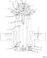
- FIG. 2 , 3 and 4 A wheel drive for a rail vehicle with a 3-part coupling system is shown.
- FIG. 2 a clutch system with a clutch half 1, which is designed as a toothed clutch, wherein the toothed clutch is in engagement with a gear (not shown) and the teeth on the front side of a transmission shaft 3.
- the first clutch half 1 has a first clutch shaft 11, in which a through-bore 8 is made centrally and axially.
- the first clutch shaft 11 is arranged axially aligned with the transmission shaft 3 and the second clutch shaft 12.
- the transmission shaft 3 has at its left end a centrally axially arranged stud bolt 4, which is screwed into the transmission shaft 3 via the inner thread 7 of the stud bolt 4. At the other end of the stud bolt 4 there is an external thread 6, onto which a nut 5 is screwed, thus connecting the transmission shaft 3 to the first coupling half 1 in a force-fitting manner.
- the transmission shaft 3 has at its right end another stud bolt 4, which is screwed into the transmission shaft 3 via the inner thread 7 of the stud bolt 4.
- the second clutch shaft 12 is arranged axially aligned with the transmission shaft 3 and the first clutch shaft 11 and is part of the second clutch half 2.
- the second coupling half 2 is designed as a ring disk coupling, which is detachably connected to the transmission shaft 3 by screwing the nut 5 to the stud bolt 4.
- the ring disk coupling is in turn connected to the wheel 9 of the rail vehicle in a force-locking and form-locking manner.
- the closure element 14 is removed from the opening of the sleeve 13 and the nut 5 is loosened and removed from the first coupling half 1 and the stud bolt 4 from the external thread 6 and then the first coupling half 1 is pulled from the stud bolt 4 and removed.
- the nut 5 is loosened from the second coupling half 2 and the stud bolt 4 from the external thread 6 and removed.
- the second coupling half 2 with earthing contact element 10 and stud bolt 4 can then be removed.
- the Fig. 3 and Fig. 4 also show a 3-part clutch system, whereby the second clutch half 2 assigned to the wheel is connected to the transmission shaft 3 via a screw 15 Fig. 3 or with a press bandage 16 according to Fig. 4 is connected.
- the Fig. 5 shows a 3-part coupling system in which the stud bolt 4 is pre-assembled axially in the second coupling half 2 assigned to the wheel.
- the stud bolt 4 extends through a through hole 8 of the aligned transmission shaft 3 and further through the through hole 8 of the first coupling half 1 assigned to the drive.
- the end of the stud bolt protrudes from the first coupling half 1, wherein the force-locking connection of the first coupling half 1, the transmission shaft 3 and the second coupling half 2 is realized by means of a nut 5 screwed onto the outer thread 6 of the stud bolt 4.
- the coupling is assembled in such a way that the stud bolt 4 is pre-assembled into the second coupling half 2 assigned to the wheel in the coupling shaft 12.
- the transmission shaft 3 with the through hole 8 is then pushed onto the stud bolt 4 and then the first coupling half 1 assigned to the drive with the through hole 8 is also pushed onto the stud bolt 4 and the coupling is connected in a force-locking manner using a nut 5.
- the correct fit of the first coupling half 1 and the transmission shaft 3 to the second coupling half 2 is checked using a test gauge through the opening of the drive-side sleeve 13 on the nut 5 and the protruding stud bolt 4. After assembly, the opening of the sleeve 13 is closed using a closure element 14.
Landscapes
- Engineering & Computer Science (AREA)
- Chemical & Material Sciences (AREA)
- Combustion & Propulsion (AREA)
- Transportation (AREA)
- Mechanical Engineering (AREA)
- Arrangement And Mounting Of Devices That Control Transmission Of Motive Force (AREA)
- Mechanical Operated Clutches (AREA)
Claims (13)
- Accouplement pour véhicules ferroviaires, contenant un système d'accouplement en 2 parties, qui présente une première moitié d'accouplement (1) tournée vers un entraînement et une deuxième moitié d'accouplement (2) tournée vers une roue (9) d'un véhicule ferroviaire, la première moitié d'accouplement (1) étant en liaison avec l'entraînement et présentant au moins un premier arbre d'accouplement (11) et un manchon (13) côté entraînement, et la deuxième moitié d'accouplement (2) étant reliée à la roue (9) du véhicule ferroviaire et présentant un deuxième arbre d'accouplement (12), le deuxième arbre d'accouplement (12) étant guidé à travers un moyeu creux de la roue (9), et le point de séparation du premier et du deuxième arbre d'accouplement (11, 12) étant réalisé de telle sorte que sur le côté frontal respectif des arbres d'accouplement (11, 12) tourné l'un vers l'autre, sont présentes des dentures ou des surfaces de frottement qui transmettent au moins un couple de rotation par adhérence et/ou par complémentarité de formes,
caractérisé en ce qu'un goujon fileté (4) prémonté, agencé axialement au centre dans le deuxième arbre d'accouplement (12), est présent au moins pour aligner, centrer, guider et contrôler la deuxième moitié d'accouplement (2) par rapport à la première moitié d'accouplement (1), le goujon fileté (4) étant agencé à l'intérieur d'un alésage traversant (8) axial au centre, qui est présent dans le premier arbre d'accouplement (11), et le goujon fileté (4) faisant saillie par une zone de la première moitié d'accouplement (1) sur le côté détourné du côté frontal du premier arbre d'accouplement (11), le goujon fileté (4) présentant au moins dans cette zone en saillie un filetage extérieur (6) sur lequel est vissé un écrou (5) avec lequel est réalisée au moins une liaison par adhérence de la première moitié d'accouplement (1) et de la deuxième moitié d'accouplement (2). - Accouplement pour véhicules ferroviaires, contenant un système d'accouplement en 3 parties, qui présente une première moitié d'accouplement (1) tournée vers un entraînement et une deuxième moitié d'accouplement (2) tournée vers une roue, et un arbre de transmission (3), la première moitié d'accouplement (1) étant en liaison avec l'entraînement et présentant au moins un premier arbre d'accouplement (11) et un manchon (13) côté entraînement, et la deuxième moitié d'accouplement (2) étant reliée à une roue (9) du véhicule ferroviaire et présentant un deuxième arbre d'accouplement (12), le deuxième arbre d'accouplement (12) étant guidé à travers un moyeu creux d'une roue (9), et le point de séparation du premier et du deuxième arbre d'accouplement (11, 12) avec l'arbre de transmission (3) étant réalisé de telle sorte que sur le côté frontal respectif, tourné l'un vers l'autre, des arbres d'accouplement (11, 12) et de l'arbre de transmission (3), sont présentes des dentures et/ou des surfaces de frottement avec lesquelles un couple de rotation peut être transmis au moins par adhérence et/ou par complémentarité de forme, un arbre de transmission (3) étant agencé en alignement axial entre les arbres d'accouplement (11, 12) des première et deuxième moitiés d'accouplement (1, 2), lequel est relié de manière amovible par la première et/ou la deuxième moitié d'accouplement (1, 2),
caractérisé en ce
qu'au moins un goujon fileté (4) prémonté, agencé axialement au centre dans l'arbre de transmission (3), est présent au moins pour aligner, centrer, guider et contrôler au moins l'arbre de transmission et la deuxième moitié d'accouplement (2) par rapport à la première moitié d'accouplement (1), le goujon fileté (4) étant agencé à l'intérieur d'un alésage de passage (8) axial au centre, qui est présent au moins dans le premier arbre d'accouplement (11), et le goujon fileté (4) faisant saillie par une zone de la première moitié d'accouplement (1) sur le côté détourné du côté frontal du premier arbre d'accouplement (11), le goujon fileté (4) présentant au moins dans cette zone en saillie un filetage extérieur (6) sur lequel est vissé un écrou (5) avec lequel est réalisée au moins une liaison par adhérence au moins de la première moitié d'accouplement (1) et de l'arbre de transmission (3). - Accouplement selon la revendication 1 ou 2, dans lequel la première moitié d'accouplement (1) est un accouplement à dents et/ou la deuxième moitié d'accouplement (2) amovible de l'arbre de transmission (3) est un accouplement à dents, un accouplement à disques annulaires, un accouplement annulaire à paquet de clavettes, un paquet de clavettes, un accouplement à pattes ou un accouplement à bras.
- Accouplement selon la revendication 2 ou 3, dans lequel la liaison de l'arbre de transmission (3) avec la première et/ou la deuxième moitié d'accouplement (1, 2) est réalisée au moyen d'une denture frontale, d'une denture plane, d'un assemblage par pression et/ou d'un vissage à bride.
- Accouplement selon au moins l'une quelconque des revendications 2 à 4, dans lequel deux goujons filetés (4) agencés axialement au centre sont prémontés dans l'arbre de transmission (3) du côté de la zone d'extrémité.
- Accouplement selon au moins l'une quelconque des revendications 2 à 4, dans lequel un goujon fileté (4) prémonté est agencé axialement au centre dans le deuxième arbre d'accouplement (12), s'étend à travers un alésage traversant (8) de l'arbre de transmission (3) et un alésage traversant (8) de la première moitié d'accouplement (1) et fait saillie de la première moitié d'accouplement (1).
- Accouplement selon au moins l'une quelconque des revendications précédentes, dans lequel l'au moins un goujon fileté (4) est vissé, collé et/ou prémonté au moyen d'un ajustement serré.
- Accouplement selon au moins l'une quelconque des revendications précédentes, dans lequel l'ajustement de l'alésage traversant (8) et du goujon fileté (4) est conçu sous forme d'ajustement glissant ou d'ajustement coulissant.
- Accouplement selon au moins l'une quelconque des revendications 2 et 4 à 6, dans lequel la liaison de l'arbre de transmission (3) et du deuxième arbre d'accouplement (12) de la deuxième moitié d'accouplement (2) tournée vers la roue (9) est réalisée au moyen d'un goujon fileté (4), d'une vis (15) côté roue ou d'un assemblage par pression (16).
- Accouplement selon au moins l'une quelconque des revendications précédentes, dans lequel le manchon (13) côté entraînement présente une ouverture avec un élément de fermeture (14).
- Accouplement selon la revendication 10, dans lequel l'élément de fermeture (14) est un bouchon de fermeture ou une vis de fermeture.
- Accouplement selon au moins l'une quelconque des revendications précédentes, dans lequel la première moitié d'accouplement (1) est en liaison avec une boîte de vitesses ou directement avec un moteur.
- Accouplement selon au moins l'une quelconque des revendications précédentes, dans lequel l'attache de la deuxième moitié d'accouplement (12) à la roue (9) et/ou à un élément de contact de terre (10) est réalisée par complémentarité de forme, par adhérence et/ou par liaison de matière.
Applications Claiming Priority (2)
| Application Number | Priority Date | Filing Date | Title |
|---|---|---|---|
| DE202019105391.7U DE202019105391U1 (de) | 2019-09-27 | 2019-09-27 | Kupplung für Schienenfahrzeuge |
| PCT/EP2020/076669 WO2021058629A1 (fr) | 2019-09-27 | 2020-09-24 | Embrayage pour véhicules ferroviaires |
Publications (3)
| Publication Number | Publication Date |
|---|---|
| EP4034445A1 EP4034445A1 (fr) | 2022-08-03 |
| EP4034445C0 EP4034445C0 (fr) | 2025-01-08 |
| EP4034445B1 true EP4034445B1 (fr) | 2025-01-08 |
Family
ID=68419526
Family Applications (1)
| Application Number | Title | Priority Date | Filing Date |
|---|---|---|---|
| EP20780652.2A Active EP4034445B1 (fr) | 2019-09-27 | 2020-09-24 | Embrayage pour véhicules ferroviaires |
Country Status (6)
| Country | Link |
|---|---|
| EP (1) | EP4034445B1 (fr) |
| CN (1) | CN114728665B (fr) |
| DE (1) | DE202019105391U1 (fr) |
| ES (1) | ES3015459T3 (fr) |
| PL (1) | PL4034445T3 (fr) |
| WO (1) | WO2021058629A1 (fr) |
Family Cites Families (20)
| Publication number | Priority date | Publication date | Assignee | Title |
|---|---|---|---|---|
| FR916946A (fr) | 1944-11-20 | 1946-12-19 | Secheron Atel | Commande individuelle d'essieu avec arbre cardan et transmission par roues dentées pour véhicules à traction électrique |
| GB599887A (en) * | 1945-10-09 | 1948-03-23 | Hindmarch Thomas | Improvements in reversing gear |
| DE4230639C1 (de) * | 1992-09-12 | 1993-10-07 | Loehr & Bromkamp Gmbh | Kugelgleichlaufdrehgelenk |
| JPH10281180A (ja) * | 1997-04-04 | 1998-10-20 | Tochigi Fuji Ind Co Ltd | カップリング |
| JP3334630B2 (ja) * | 1998-07-31 | 2002-10-15 | 日本電気株式会社 | 映像/音声データ一斉配信方法及び多地点テレビ会議システム |
| JP4009428B2 (ja) * | 2001-02-13 | 2007-11-14 | Ntn株式会社 | 駆動車輪用軸受装置 |
| DE10050757A1 (de) | 2000-10-13 | 2002-04-25 | Zahnradfabrik Friedrichshafen | Antriebseinheit für Schienenfahrzeuge |
| JP3853707B2 (ja) * | 2002-06-18 | 2006-12-06 | 三菱電機株式会社 | 車両用伝動装置 |
| DE202005015769U1 (de) | 2005-09-30 | 2006-01-19 | Kwd Kupplungswerk Dresden Gmbh | Kardanische Doppelgelenkkupplung für Schienenfahrzeuge |
| US7648211B2 (en) * | 2007-06-19 | 2010-01-19 | Shimano Inc. | Bicycle wheel securing structure |
| DE102011086020A1 (de) | 2011-11-09 | 2013-05-16 | Zf Friedrichshafen Ag | Getriebeeinheit |
| EP2669135B1 (fr) * | 2012-05-30 | 2015-01-14 | Bombardier Transportation GmbH | Agencement de commande pour train roulant |
| CN203496892U (zh) * | 2013-09-30 | 2014-03-26 | 南车株洲电力机车有限公司 | 一种低地板车齿轮箱与轮对间连接结构 |
| DE202014000506U1 (de) * | 2014-01-14 | 2014-02-27 | Kwd Kupplungswerk Dresden Gmbh | Kupplung mit über eine Mitnahmeverbindung miteinander in Verbindung stehenden Kupplungshälften |
| DE102014204590A1 (de) * | 2014-03-12 | 2015-09-17 | Siemens Aktiengesellschaft | Zahnkupplung |
| DE102015112102A1 (de) * | 2015-07-24 | 2017-01-26 | Gkn Driveline International Gmbh | Kupplungsmodul für einen Antriebsstrang und Antriebsanordnung mit einem Kupplungsmodul |
| DE102015222125A1 (de) * | 2015-11-10 | 2017-05-11 | Bombardier Transportation Gmbh | Antriebsanordnung für ein Schienenfahrzeug, Schienenfahrzeug mit der Antriebsanordnung und Verfahren zur Herstellung |
| CN105460023B (zh) * | 2015-12-25 | 2017-12-12 | 中车戚墅堰机车车辆工艺研究所有限公司 | 低地板轨道车辆用齿轮箱 |
| DE102017218015A1 (de) * | 2016-10-26 | 2018-04-26 | Aktiebolaget Skf | Bolzenanordnung, Verbindungsanordnung und Verfahren zum Befestigen einer Verbindungsanordnung |
| DE102017102138A1 (de) * | 2017-02-03 | 2018-08-09 | Andreas Fiedler | System zur Verbindung eines Getriebes mit einer Radsatzwelle und Anordnung für ein Drehgestell für Schienenfahrzeuge |
-
2019
- 2019-09-27 DE DE202019105391.7U patent/DE202019105391U1/de active Active
-
2020
- 2020-09-24 ES ES20780652T patent/ES3015459T3/es active Active
- 2020-09-24 EP EP20780652.2A patent/EP4034445B1/fr active Active
- 2020-09-24 CN CN202080081111.3A patent/CN114728665B/zh active Active
- 2020-09-24 WO PCT/EP2020/076669 patent/WO2021058629A1/fr not_active Ceased
- 2020-09-24 PL PL20780652.2T patent/PL4034445T3/pl unknown
Also Published As
| Publication number | Publication date |
|---|---|
| EP4034445A1 (fr) | 2022-08-03 |
| EP4034445C0 (fr) | 2025-01-08 |
| CN114728665A (zh) | 2022-07-08 |
| PL4034445T3 (pl) | 2025-05-05 |
| ES3015459T3 (en) | 2025-05-05 |
| CN114728665B (zh) | 2025-02-25 |
| WO2021058629A1 (fr) | 2021-04-01 |
| DE202019105391U1 (de) | 2019-10-16 |
Similar Documents
| Publication | Publication Date | Title |
|---|---|---|
| DE102018113329B4 (de) | STRAßENRADAKTUATORANORDNUNG | |
| DE102005003388A1 (de) | Schraubenloses Befestigungssystem für ein Gleichlaufgelenk | |
| EP3327303A1 (fr) | Dispositif de raccordement permettant de raccorder un arbre à un composant | |
| EP3573844B1 (fr) | Roue pour véhicules ferroviaires | |
| EP1940667B1 (fr) | Transmission a joint a double cardan de vehicules sur rails | |
| EP2776299B1 (fr) | Unité transmission | |
| DE102004008538B4 (de) | Differential mit einer Bolzenbefestigungsbaugruppe | |
| DE102012216298A1 (de) | Winkelgetriebe | |
| EP1872025B1 (fr) | Accouplement a friction pour au moins une roue porteuse d'un vehicule automoteur sur rails | |
| AT517763B1 (de) | Anordnung zur Drehverbindung einer Belastungsmaschine eines Prüfstandes mit einem Prüfling | |
| EP4034445B1 (fr) | Embrayage pour véhicules ferroviaires | |
| DE19702682A1 (de) | Achs- und/oder Winkelversatz ausgleichender Antriebsverbindung | |
| EP1377489B1 (fr) | Dispositif d'entrainement de vehicule a accouplement a denture spherique | |
| EP4143453A1 (fr) | Raccord double et mobile pour liaison à compensation de décalage de deux arbres | |
| DE102014204221B4 (de) | Ausgleichskupplung mit Distanzelement sowie Kupplungsanordnung | |
| EP0905002B1 (fr) | Dispositif de freinage pour véhicules ferroviaires | |
| EP0315922B1 (fr) | Accouplement à disques | |
| EP1360425B1 (fr) | Entraineur a bride | |
| WO2023152231A1 (fr) | Système de double couplage pour l'entraînement de véhicules ferroviaires | |
| EP3686076A1 (fr) | Boîtier de transmission et agencement de support d'une transmission | |
| DE102018219600B4 (de) | Dämpfungseinrichtung für einen Antriebsstrang eines Kraftfahrzeugs, Antriebsstrang für ein Kraftfahrzeug, sowie Kraftfahrzeug | |
| DE102023200553A1 (de) | Getriebe mit einer Planetenstufe | |
| DE102024204084A1 (de) | Antriebsvorrichtung für ein Flurförderzeug und Flurförderzeug | |
| DE202014000506U1 (de) | Kupplung mit über eine Mitnahmeverbindung miteinander in Verbindung stehenden Kupplungshälften | |
| DE102023209091A1 (de) | Ausgleichskupplung zum versatzausgleichenden Verbinden zweier Wellen |
Legal Events
| Date | Code | Title | Description |
|---|---|---|---|
| STAA | Information on the status of an ep patent application or granted ep patent |
Free format text: STATUS: UNKNOWN |
|
| STAA | Information on the status of an ep patent application or granted ep patent |
Free format text: STATUS: THE INTERNATIONAL PUBLICATION HAS BEEN MADE |
|
| PUAI | Public reference made under article 153(3) epc to a published international application that has entered the european phase |
Free format text: ORIGINAL CODE: 0009012 |
|
| STAA | Information on the status of an ep patent application or granted ep patent |
Free format text: STATUS: REQUEST FOR EXAMINATION WAS MADE |
|
| 17P | Request for examination filed |
Effective date: 20220412 |
|
| AK | Designated contracting states |
Kind code of ref document: A1 Designated state(s): AL AT BE BG CH CY CZ DE DK EE ES FI FR GB GR HR HU IE IS IT LI LT LU LV MC MK MT NL NO PL PT RO RS SE SI SK SM TR |
|
| DAV | Request for validation of the european patent (deleted) | ||
| DAX | Request for extension of the european patent (deleted) | ||
| GRAP | Despatch of communication of intention to grant a patent |
Free format text: ORIGINAL CODE: EPIDOSNIGR1 |
|
| STAA | Information on the status of an ep patent application or granted ep patent |
Free format text: STATUS: GRANT OF PATENT IS INTENDED |
|
| INTG | Intention to grant announced |
Effective date: 20240808 |
|
| GRAS | Grant fee paid |
Free format text: ORIGINAL CODE: EPIDOSNIGR3 |
|
| GRAA | (expected) grant |
Free format text: ORIGINAL CODE: 0009210 |
|
| STAA | Information on the status of an ep patent application or granted ep patent |
Free format text: STATUS: THE PATENT HAS BEEN GRANTED |
|
| AK | Designated contracting states |
Kind code of ref document: B1 Designated state(s): AL AT BE BG CH CY CZ DE DK EE ES FI FR GB GR HR HU IE IS IT LI LT LU LV MC MK MT NL NO PL PT RO RS SE SI SK SM TR |
|
| REG | Reference to a national code |
Ref country code: GB Ref legal event code: FG4D Free format text: NOT ENGLISH |
|
| REG | Reference to a national code |
Ref country code: CH Ref legal event code: EP |
|
| REG | Reference to a national code |
Ref country code: DE Ref legal event code: R096 Ref document number: 502020010167 Country of ref document: DE |
|
| REG | Reference to a national code |
Ref country code: IE Ref legal event code: FG4D Free format text: LANGUAGE OF EP DOCUMENT: GERMAN |
|
| U01 | Request for unitary effect filed |
Effective date: 20250203 |
|
| U07 | Unitary effect registered |
Designated state(s): AT BE BG DE DK EE FI FR IT LT LU LV MT NL PT RO SE SI Effective date: 20250211 |
|
| PG25 | Lapsed in a contracting state [announced via postgrant information from national office to epo] |
Ref country code: RS Free format text: LAPSE BECAUSE OF FAILURE TO SUBMIT A TRANSLATION OF THE DESCRIPTION OR TO PAY THE FEE WITHIN THE PRESCRIBED TIME-LIMIT Effective date: 20250408 |
|
| PG25 | Lapsed in a contracting state [announced via postgrant information from national office to epo] |
Ref country code: NO Free format text: LAPSE BECAUSE OF FAILURE TO SUBMIT A TRANSLATION OF THE DESCRIPTION OR TO PAY THE FEE WITHIN THE PRESCRIBED TIME-LIMIT Effective date: 20250408 Ref country code: IS Free format text: LAPSE BECAUSE OF FAILURE TO SUBMIT A TRANSLATION OF THE DESCRIPTION OR TO PAY THE FEE WITHIN THE PRESCRIBED TIME-LIMIT Effective date: 20250508 |
|
| PG25 | Lapsed in a contracting state [announced via postgrant information from national office to epo] |
Ref country code: HR Free format text: LAPSE BECAUSE OF FAILURE TO SUBMIT A TRANSLATION OF THE DESCRIPTION OR TO PAY THE FEE WITHIN THE PRESCRIBED TIME-LIMIT Effective date: 20250108 |
|
| PG25 | Lapsed in a contracting state [announced via postgrant information from national office to epo] |
Ref country code: GR Free format text: LAPSE BECAUSE OF FAILURE TO SUBMIT A TRANSLATION OF THE DESCRIPTION OR TO PAY THE FEE WITHIN THE PRESCRIBED TIME-LIMIT Effective date: 20250409 |
|
| REG | Reference to a national code |
Ref country code: CH Ref legal event code: U11 Free format text: ST27 STATUS EVENT CODE: U-0-0-U10-U11 (AS PROVIDED BY THE NATIONAL OFFICE) Effective date: 20251001 |
|
| PG25 | Lapsed in a contracting state [announced via postgrant information from national office to epo] |
Ref country code: SM Free format text: LAPSE BECAUSE OF FAILURE TO SUBMIT A TRANSLATION OF THE DESCRIPTION OR TO PAY THE FEE WITHIN THE PRESCRIBED TIME-LIMIT Effective date: 20250108 |
|
| PGFP | Annual fee paid to national office [announced via postgrant information from national office to epo] |
Ref country code: PL Payment date: 20250915 Year of fee payment: 6 |
|
| PGFP | Annual fee paid to national office [announced via postgrant information from national office to epo] |
Ref country code: CZ Payment date: 20250912 Year of fee payment: 6 |
|
| PG25 | Lapsed in a contracting state [announced via postgrant information from national office to epo] |
Ref country code: SK Free format text: LAPSE BECAUSE OF FAILURE TO SUBMIT A TRANSLATION OF THE DESCRIPTION OR TO PAY THE FEE WITHIN THE PRESCRIBED TIME-LIMIT Effective date: 20250108 |
|
| U20 | Renewal fee for the european patent with unitary effect paid |
Year of fee payment: 6 Effective date: 20250922 |
|
| PLBE | No opposition filed within time limit |
Free format text: ORIGINAL CODE: 0009261 |
|
| STAA | Information on the status of an ep patent application or granted ep patent |
Free format text: STATUS: NO OPPOSITION FILED WITHIN TIME LIMIT |
|
| 26N | No opposition filed |
Effective date: 20251009 |
|
| PGFP | Annual fee paid to national office [announced via postgrant information from national office to epo] |
Ref country code: CH Payment date: 20251001 Year of fee payment: 6 |
|
| PGFP | Annual fee paid to national office [announced via postgrant information from national office to epo] |
Ref country code: ES Payment date: 20251020 Year of fee payment: 6 |