EP4033743B1 - Stützvorrichtung - Google Patents
Stützvorrichtung Download PDFInfo
- Publication number
- EP4033743B1 EP4033743B1 EP20941785.6A EP20941785A EP4033743B1 EP 4033743 B1 EP4033743 B1 EP 4033743B1 EP 20941785 A EP20941785 A EP 20941785A EP 4033743 B1 EP4033743 B1 EP 4033743B1
- Authority
- EP
- European Patent Office
- Prior art keywords
- clamping
- interface
- boss
- joint structure
- embedding
- Prior art date
- Legal status (The legal status is an assumption and is not a legal conclusion. Google has not performed a legal analysis and makes no representation as to the accuracy of the status listed.)
- Active
Links
Images


Classifications
-
- H—ELECTRICITY
- H04—ELECTRIC COMMUNICATION TECHNIQUE
- H04M—TELEPHONIC COMMUNICATION
- H04M1/00—Substation equipment, e.g. for use by subscribers
- H04M1/02—Constructional features of telephone sets
- H04M1/04—Supports for telephone transmitters or receivers
-
- F—MECHANICAL ENGINEERING; LIGHTING; HEATING; WEAPONS; BLASTING
- F16—ENGINEERING ELEMENTS AND UNITS; GENERAL MEASURES FOR PRODUCING AND MAINTAINING EFFECTIVE FUNCTIONING OF MACHINES OR INSTALLATIONS; THERMAL INSULATION IN GENERAL
- F16M—FRAMES, CASINGS OR BEDS OF ENGINES, MACHINES OR APPARATUS, NOT SPECIFIC TO ENGINES, MACHINES OR APPARATUS PROVIDED FOR ELSEWHERE; STANDS; SUPPORTS
- F16M11/00—Stands or trestles as supports for apparatus or articles placed thereon ; Stands for scientific apparatus such as gravitational force meters
- F16M11/02—Heads
- F16M11/04—Means for attachment of apparatus; Means allowing adjustment of the apparatus relatively to the stand
- F16M11/041—Allowing quick release of the apparatus
-
- F—MECHANICAL ENGINEERING; LIGHTING; HEATING; WEAPONS; BLASTING
- F16—ENGINEERING ELEMENTS AND UNITS; GENERAL MEASURES FOR PRODUCING AND MAINTAINING EFFECTIVE FUNCTIONING OF MACHINES OR INSTALLATIONS; THERMAL INSULATION IN GENERAL
- F16M—FRAMES, CASINGS OR BEDS OF ENGINES, MACHINES OR APPARATUS, NOT SPECIFIC TO ENGINES, MACHINES OR APPARATUS PROVIDED FOR ELSEWHERE; STANDS; SUPPORTS
- F16M11/00—Stands or trestles as supports for apparatus or articles placed thereon ; Stands for scientific apparatus such as gravitational force meters
- F16M11/02—Heads
- F16M11/04—Means for attachment of apparatus; Means allowing adjustment of the apparatus relatively to the stand
- F16M11/06—Means for attachment of apparatus; Means allowing adjustment of the apparatus relatively to the stand allowing pivoting
- F16M11/10—Means for attachment of apparatus; Means allowing adjustment of the apparatus relatively to the stand allowing pivoting around a horizontal axis
- F16M11/105—Means for attachment of apparatus; Means allowing adjustment of the apparatus relatively to the stand allowing pivoting around a horizontal axis the horizontal axis being the roll axis, e.g. for creating a landscape-portrait rotation
-
- F—MECHANICAL ENGINEERING; LIGHTING; HEATING; WEAPONS; BLASTING
- F16—ENGINEERING ELEMENTS AND UNITS; GENERAL MEASURES FOR PRODUCING AND MAINTAINING EFFECTIVE FUNCTIONING OF MACHINES OR INSTALLATIONS; THERMAL INSULATION IN GENERAL
- F16M—FRAMES, CASINGS OR BEDS OF ENGINES, MACHINES OR APPARATUS, NOT SPECIFIC TO ENGINES, MACHINES OR APPARATUS PROVIDED FOR ELSEWHERE; STANDS; SUPPORTS
- F16M13/00—Other supports for positioning apparatus or articles; Means for steadying hand-held apparatus or articles
- F16M13/005—Other supports for positioning apparatus or articles; Means for steadying hand-held apparatus or articles integral with the apparatus or articles to be supported
-
- F—MECHANICAL ENGINEERING; LIGHTING; HEATING; WEAPONS; BLASTING
- F16—ENGINEERING ELEMENTS AND UNITS; GENERAL MEASURES FOR PRODUCING AND MAINTAINING EFFECTIVE FUNCTIONING OF MACHINES OR INSTALLATIONS; THERMAL INSULATION IN GENERAL
- F16M—FRAMES, CASINGS OR BEDS OF ENGINES, MACHINES OR APPARATUS, NOT SPECIFIC TO ENGINES, MACHINES OR APPARATUS PROVIDED FOR ELSEWHERE; STANDS; SUPPORTS
- F16M13/00—Other supports for positioning apparatus or articles; Means for steadying hand-held apparatus or articles
- F16M13/02—Other supports for positioning apparatus or articles; Means for steadying hand-held apparatus or articles for supporting on, or attaching to, an object, e.g. tree, gate, window-frame, cycle
- F16M13/022—Other supports for positioning apparatus or articles; Means for steadying hand-held apparatus or articles for supporting on, or attaching to, an object, e.g. tree, gate, window-frame, cycle repositionable
-
- F—MECHANICAL ENGINEERING; LIGHTING; HEATING; WEAPONS; BLASTING
- F16—ENGINEERING ELEMENTS AND UNITS; GENERAL MEASURES FOR PRODUCING AND MAINTAINING EFFECTIVE FUNCTIONING OF MACHINES OR INSTALLATIONS; THERMAL INSULATION IN GENERAL
- F16M—FRAMES, CASINGS OR BEDS OF ENGINES, MACHINES OR APPARATUS, NOT SPECIFIC TO ENGINES, MACHINES OR APPARATUS PROVIDED FOR ELSEWHERE; STANDS; SUPPORTS
- F16M2200/00—Details of stands or supports
- F16M2200/02—Locking means
- F16M2200/021—Locking means for rotational movement
- F16M2200/024—Locking means for rotational movement by positive interaction, e.g. male-female connections
-
- G—PHYSICS
- G06—COMPUTING OR CALCULATING; COUNTING
- G06F—ELECTRIC DIGITAL DATA PROCESSING
- G06F1/00—Details not covered by groups G06F3/00 - G06F13/00 and G06F21/00
- G06F1/16—Constructional details or arrangements
- G06F1/1613—Constructional details or arrangements for portable computers
- G06F1/1626—Constructional details or arrangements for portable computers with a single-body enclosure integrating a flat display, e.g. Personal Digital Assistants [PDAs]
Definitions
- the present disclosure relates to a technical field of supports, and in particular to a support device.
- US 2003/160138 A1 discloses an adjustable stand for rotatably and releasably supporting a flat panel display together with a display device usable with the stand.
- the display includes a boss projecting from a rear surface thereof, which boss is received in an arc-shaped channel in a plate portion of the stand.
- the stand further includes two hingedly connected legs and selective locking devices for controlling the angle between the legs.
- US 2018/167498 A1 discloses a stand for a personal electronic device, which includes a base portion collapsably coupled to a further supporting portion and the personal electronic device.
- WO 2020/111406 A1 discloses a selfie stick combined with a holder, which comprises: a case main body; an attachment disc plate attached to the rear surface of the case main body; a case main body support part comprising an attachment disc plate coupling part, which is coupled to the attachment disc plate so as to be rotatable, and an extended part extended from the attachment disc plate coupling part; a folding part hinge-coupled so as to be folded in a separable manner from the case main body support part; a folding part support part which is extended in the longitudinal direction of the folding part so as to support the folding part, and which acts as a holder and a handle; and a first extension rod and a second extension rod, which separate the folding part support part from the folding part so as to act as a selfie stick together with the folding part and the folding part support part.
- CN 209 545 661 U discloses a structure capable of being used for rapid dismounting and rotary positioning of support products, and comprising a back plate body, a sliding groove fixedly connected to the right side of the back plate body. A positioning hole is formed in the back plate body, a clamping buckle is movably connected to the right side of the back plate body and located in the sliding groove.
- Damping clamping teeth are fixedly connected to the left side of the sliding groove, a positioning column located in the positioning hole is fixedly connected to the right side of the clamping buckle, a secondary positioning column is fixedly connected to the right side of the positioning column, a mobile phone fixing back sleeve is fixedly connected to the right side of the secondary positioning column, and a reducing grid is fixedly connected to the interior of the sliding groove.
- the present disclosure provides a support device to solve technical problems that when the present support devices are in use, there is a defect that the electronic products cannot be removed quickly.
- the present disclosure provides a support device, including a mounting frame and a clamping base.
- the mounting frame includes a main frame body and a joint structure, electronic products are installed on a front side of the main frame body, and the joint structure is connected with a rear side of the main frame body.
- the joint structure is detachably connected with the clamping base. When the joint structure is detachably connected with the clamping base, the joint structure is adapted to adjust positions and is fixedly clamped corresponding to the clamping base.
- the clamping base includes a main base body.
- the main base body includes a transfer cavity, a plug-in interface, and a transfer interface.
- the plug-in interface and the transfer interface are communicated with the transfer cavity, and the plug-in interface is communicated with the transfer interface.
- the joint structure includes a boss and a limiting component. One end of the boss is connected with a rear side surface of the main frame body, and another end of the boss extends towards a position far away from the main frame body. One end of the limiting component is connected with the boss.
- An outer contour of a cross section of the boss is a long-strip oval. Two planes facing oppositely and two arcuate surfaces facing oppositely are disposed on an outer side of the boss.
- any one of the arcuate surfaces of the boss directly faces the plug-in interface and is laterally inserted into the transfer interface through the plug-in interface. At this moment, another end of the limiting component is located in the transfer cavity and clamped into the transfer interface.
- the joint structure is adapted to rotate corresponding to the main base body so that the plug-in interface faces any one of the planes.
- the main base body further includes a sliding connection channel and a sliding interface.
- the sliding interface is communicated with the transfer interface, and the sliding interface and the transfer interface are located on a front side of the main base body.
- the sliding connection channel is communicated with the transfer cavity, and an opening, far away from the transfer cavity, of the sliding connection channel is the plug-in interface.
- the plug-in interface is communicated with the sliding interface.
- the limiting component includes a limiting plate and at least two clamping pins, one end of each of the clamping pins is connected with a plate surface of the limiting plate, and each of the clamping pins is circumferentially evenly distributed around a centerline of the limiting plate.
- a clamping hole is formed on the mounting frame, and the clamping hole extends from an end surface of the boss to a front side surface of the main frame body.
- the mounting frame further includes a clamping ring, the clamping ring is circumferentially disposed on a hole wall of the clamping hole, and each of the clamping pins is inserted into the clamping ring through the clamping hole of the boss and is clamping in the clamping ring.
- the mounting frame further includes an embedding component, and a front-and-back penetrating embedding hole is disposed on the embedding component.
- the embedding component is embedded in the mounting frame, and a centerline of the clamping hole is also a centerline of the embedding hole.
- the embedding component includes an embedding table having the embedding hole and an embedding plate diverging from a peripheral side wall of the embedding table.
- the embedded plate has at least one step and is embedded inside the main frame body, and the embedding table is embedded in the boss.
- the embedding component further includes an embedding ring, the embedding ring is connected with a front end of the embedding table.
- the embedding ring extends towards the clamping hole, and the embedding ring is the clamping ring.
- the limiting component further includes a positioning protrusion, the positioning protrusion is connected with a plate surface of the limiting plate, and the plate surface of the limiting plate is opposite to each of the clamping pins.
- the clamping base further includes a positioning table, the positioning table is fixed to a cavity wall of the transfer cavity, the cavity wall faces the transfer interface, and a positioning groove is disposed on the positioning table.
- the positioning protrusion preferably is inserted into the positioning groove.
- a surface facing the plug-in interface, of the positioning table is a guide inclined surface, and the guide inclined surface is inclined towards a mounting direction of the joint structure.
- the joint structure further includes an annular limiting table and a plurality of strip-shaped limiting teeth.
- One end of the annular limiting table is connected with the rear side surface of the main frame body, and another end of the annular limiting table extends towards the position far away from the main frame body.
- the plurality of the strip-shaped limiting teeth is connected with a rear table surface of the annular limiting table.
- the annular limiting table is sleeved on a periphery of the boss, and a height of the annular limiting table is smaller than a height of the boss.
- the clamping base further includes a plurality of strip-shaped clamping teeth, the plurality of the strip-shaped clamping teeth are connected with a front side surface of the main base body. Extension lines of each of the strip-shaped clamping teeth intersect a centerline of the transfer interface, and the extension lines of each of the strip-shaped clamping teeth are circumferentially spaced and are evenly disposed around the centerline of the transfer interface.
- the clamping base further includes a guide bump
- the guide bump is connected with the front side surface of the main base body.
- the joint structure further includes a spacer ring.
- One end of the spacer ring is connected with the rear side surface of the main frame body, and another end of the spacer ring extends towards the position far away from the main frame body.
- the spacer ring is sleeved on a periphery of the annular limiting table.
- An inner side wall of the spacer ring, an outer side wall of the annular limiting table, and a surface, between the inner side wall of the spacer ring and the outer side wall of the annular limiting table, of the rear side surface of the main frame body form an annular guide groove.
- the centerline of the boss is also a centerline of the annular guide groove.
- a notch is formed on a position, facing any one of the arcuate surfaces, of the spacer ring.
- the joint structure further includes a plurality of stabilizing teeth, the plurality stabilizing teeth are connected with the rear side surface of the main frame body. Extension lines of each of the stabilizing teeth intersect the centerline of the boss, and the extension lines of each of the stabilizing teeth are circumferentially spaced and are evenly disposed around the centerline of the boss.
- the guide pump is inserted between any two adjacent stabilizing teeth.
- the mounting frame further includes a packaging sheet, a packaging groove is formed on the front side surface of the main frame body and on a peripheral side of a hole opening of the clamping hole.
- the packaging sheet is adapted to the packaging groove and fixed to the packaging groove.
- the clamping base includes two hanging lugs, and the two hanging lugs respectively connected with two opposite sides of the main base body.
- a hanging hole is formed on each of the hanging lugs so that a strap penetrates the hanging hole.
- the clamping base further includes a semi-fixing sleeve and a fastening strip.
- the semi-fixing sleeve is fixedly connected with a rear side of the main base body, and one end of the fastening strip is connected with one end of the semi-fixing sleeve. And another end of the fastening strip is detachably connected with another end of the semi-fixing sleeve.
- the support device includes the mounting frame and the clamping base, the mounting frame includes the main frame body and the joint structure.
- the electronic products are installed on the front side of the main frame body, the joint structure joint is connected with the rear side of the main frame body, and the joint structure and the clamping base are detachably connected.
- the joint structure adjusts positions and is fixedly clamped corresponding to the clamping base, which realizes adjustability of the mounting frame, to better ensure stability when the mounting frame and the clamping base are assembled together and further improves users' experience.
- an element when referred to as being “fixed to” or “disposed” on another element, it may be directly on another element or it may be indirectly fixed to or disposed on another element through a third component.
- an element When an element is said to be “connected with” another element, it may be directly connected with another element or it may be indirectly connected with another element through a third component.
- X indicates a direction of a front side
- Y is an opposite direction of the X, which indicates a direction of a rear side.
- first and second are used for description purposes only, and cannot be understood as indicating or implying relative importance or implicitly indicating the number of technical features indicated.
- the features defined as “first” and “second” may explicitly or implicitly include one or more of the features.
- the meaning of “plurality” is two or more, unless otherwise specifically limited.
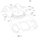
- the present disclosure provides a support device, including a mounting frame 100 and a clamping base 200.
- the mounting frame 100 includes a main frame body 110 and a joint structure 120, electronic products are installed on a front side of the main frame body 110.
- the electronic products may be different brands, different models of mobile phones, I pads, etc.
- the main frame body 110 may be a specific mounting frame 100 for installing the electronic products, or may be a housing that protects electronic products.
- the joint structure 120 is connected with a rear side of the main frame body 110.
- the joint structure 120 is detachably connected with the clamping base 200. When the joint structure 120 is detachably connected with the clamping base 200, the joint structure 120 adjusts positions and is fixedly clamped corresponding to the clamping base 200.
- the support device includes the mounting frame 100 and the clamping base 200
- the mounting frame 100 includes the main frame body 110 and the joint structure 120.
- the electronic products are installed on the front side of the main frame body 110
- the joint structure j oint is connected with the rear side of the main frame body 110
- the j oint structure 120 and the clamping base 200 are detachably connected.
- the joint structure 120 adjusts positions and is fixedly clamped corresponding to the clamping base, which realizes adjustability of the mounting frame 100, to better ensure stability when the mounting frame 100 and the clamping base 200 are assembled together and further improves users' experience.
- the clamping base 200 includes a main base body 210.
- the main base body 210 includes a transfer cavity 201, a plug-in interface 202, and a transfer interface 203.
- the plug-in interface 202 and the transfer interface 203 are communicated with the transfer cavity 201, and the plug-in interface 202 is communicated with the transfer interface 203.
- the transfer interface 203 is disposed on a front side of the main base body 210.
- the joint structure 120 includes a boss 121 and a limiting component 122.
- One end of the boss 121 is connected with a rear side surface of the main frame body 110, and another end of the boss 121 extends towards a position far away from the main frame body 110.
- One end of the limiting component 122 is connected with the boss 121.
- An outer contour of a cross section of the boss 121 is a long-strip oval.
- Two planes 1211 facing oppositely and two arcuate surfaces 1212 facing oppositely are disposed on an outer side of the boss.
- any one of the arcuate surfaces 1212 of the boss 121 directly faces the plug-in interface 202 and is laterally inserted into the transfer interface 203 through the plug-in interface 202. At this moment, another end of the limiting component 122 is located in the transfer cavity 201 and clamped into the transfer interface 203.
- the joint structure 120 rotates corresponding to the main base body 210 so that the plug-in interface 202 faces any one of the planes 1211.
- the plug interface 202 is just for the boss 121 to insert along a length direction.
- the joint structure 120 rotates corresponding to the main base body 210 so that the plug-in interface 202 faces any one of the planes 1211.
- the boss 121 is effectively avoided from sliding out the plug-in interface 202 and plays a limiting role for the joint structure 120.
- the centerline of the boss 121 is a rotation axis of the boss 121, and is also an axis of the transfer interface 203.
- the main base body 210 further includes a sliding connection channel 204 and a sliding interface 205.
- the sliding interface 205 is communicated with the transfer interface 203, and the sliding interface 205 and the transfer interface 203 are located on a front side of the main base body 210.
- the sliding connection channel 204 is communicated with the transfer cavity 201, and an opening, far away from the transfer cavity 201, of the sliding connection channel 204 is the plug-in interface 202.
- the plug-in interface 202 is communicated with the sliding interface 205.
- any one of the arcuate surfaces 1212 of the boss 121 directly faces the plug-in interface 202 and is laterally inserted into the sliding interface 205 through the plug-in interface 202.
- a limiting end of the limiting component 122 is located at the sliding connection channel 204 and is clamped into the sliding interface 205.
- the main base body 210 includes a guide surface 206, the guide surface is disposed on a position far away from the transfer cavity 201,inside the sliding interface 205.
- the guide surface may be a guide inclined surface and may also be a guide arc surface. Then positioning and installing of the joint structure 120 is realized, and assembly efficiency of the joint structure 120 improved.
- the limiting component 122 includes a limiting plate 1221 and at least two clamping pins 1222, one end of each of the clamping pins 1222 is connected with a plate surface of the limiting plate 1221, and each of the clamping pins 1222 is circumferentially evenly distributed around a centerline of the limiting plate 1221.
- a clamping hole 101 is formed on the mounting frame 100, and the clamping hole 101 extends from an end surface of the boss 121 to a front side surface of the main frame body 110.
- the mounting frame 100 further includes a clamping ring 133, the clamping ring 133 is circumferentially disposed on a hole wall of the clamping hole 101, and each of the clamping pins 1222 is inserted into the clamping ring 133 through the clamping hole 101 of the boss 121 and is clamping in the clamping ring 133.
- each of the clamping pins 1222 when the limiting component 122 needs to be installed on the boss 121, each of the clamping pins 1222 is inserted into the clamping hole 101 and is pushed ahead along the hole wall. At this moment, each of the clamping pins 1222 is acted upon by a counteracting force of the hole wall and is elastically folded. When a clamping end of each of the clamping pins 1222 extends out of the clamping ring 133, each of the clamping pins 1222 elastically expands and clamps in a front side end surface of the clamping ring 133 under an action of each of the clamping pins 1222's own elastic restoring force.
- the mounting frame 100 further includes an embedding component 130, and a front-and-back penetrating embedding hole 1301 is disposed on the embedding component 130.
- the embedding component 130 is embedded in the mounting frame 100, and a centerline of the clamping hole is also a centerline of the embedding hole. In this way, strength of a joint of the mounting frame 100 and the clamping base 200 is effectively improved.
- both the main frame body 110 and the j oint structure 120 are plastic components.
- the embedding component 130 may be a metal component and may also be a plastic component. But hardness of the embedding component 130 is higher than the main frame body 110 and the joint structure 120.
- the embedding component 130 and the mounting frame 100 are injection molded together.
- the embedding component 130 includes an embedding table 131 having the embedding hole 1301 and an embedding plate 132 diverging from a peripheral side wall of the embedding table 131.
- the embedded plate 132 has at least one step and is embedded inside the main frame body 110, and the embedding table 131 is embedded in the boss 121.
- the embedding component 130 further includes an embedding ring, the embedding ring is connected with a front end of the embedding table 131.
- the embedding ring extends towards the clamping hole 101, and the embedding ring is the clamping ring 133. In the way, installing stability of the limiting component 122 is improved.
- the limiting component 122 further includes a positioning protrusion 1223, the positioning protrusion 1223 is connected with a plate surface of the limiting plate 1221, and the plate surface of the limiting plate 1221 is opposite to each of the clamping pins 1222.
- the clamping base 200 further includes a positioning table 220, the positioning table 220 is fixed to a cavity wall of the transfer cavity 201, the cavity wall faces the transfer interface 203, and a positioning groove 207 is disposed on the positioning table 220.
- the positioning protrusion 1223 is inserted into the positioning groove 207.
- the positioning protrusion 1223 of the limiting component 122 is inserted and matched with the positioning groove 207 of the clamping base 200 to install the mounting frame 100 in place, mounting efficiency is improved and a prompting effect is realized.
- a surface facing the plug-in interface 202, of the positioning table 220 is a guide inclined surface 208, and the guide inclined surface 208 is inclined towards a mounting direction of the joint structure 120. In this way, the mounting frame is successfully installed in place.
- the joint structure 120 further includes an annular limiting table 123 and a plurality of strip-shaped limiting teeth 124.
- One end of the annular limiting table 123 is connected with the rear side surface of the main frame body 110, and another end of the annular limiting table 123 extends towards the position far away from the main frame body 110.
- the plurality of the strip-shaped limiting teeth 124 is connected with a rear table surface of the annular limiting table 123.
- the annular limiting table 123 is sleeved on a periphery of the boss 121, and a height of the annular limiting table 123 is smaller than a height of the boss 121.
- Extension lines of each of the strip-shaped limiting teeth 124 intersect a centerline of the boss 121, and the extension lines of each of the strip-shaped limiting teeth 124 are circumferentially spaced and are evenly disposed around the centerline of the boss 121.
- the clamping base 200 further includes a plurality of strip-shaped clamping teeth 230, the plurality of the strip-shaped clamping teeth 230 are connected with a front side surface of the main base body 210. Extension lines of each of the strip-shaped clamping teeth 230 intersect a centerline of the transfer interface 203, and the extension lines of each of the strip-shaped clamping teeth 230 are circumferentially spaced and are evenly disposed around the centerline of the transfer interface 203.
- each of the strip-shaped limiting teeth 124 is respectively inserted between any two adjacent strip-shaped clamping teeth 230.
- each of the strip-shaped limiting teeth 124 of the j oint structure 120 is respectively inserted between any two adjacent strip-shaped clamping teeth 230 of the clamping base 200.
- the joint structure 120 is realized to lock with the clamping base 200, which improve stability of the j oint structure 120.
- the clamping base 200 further includes a guide bump (not shown in the drawings), and the guide bump is connected with the front side surface of the main base body 210.
- the joint structure 120 further includes a spacer ring 125.
- One end of the spacer ring 125 is connected with the rear side surface of the main frame body 110, and another end of the spacer ring 125 extends towards the position far away from the main frame body 110.
- the spacer ring 125 is sleeved on a periphery of the annular limiting table 123.
- An inner side wall of the spacer ring 125, an outer side wall of the annular limiting table 123, and a surface, between the inner side wall of the spacer ring 125 and the outer side wall of the annular limiting table 123, of the rear side surface of the main frame body 110 form an annular guide groove 1201.
- the centerline of the boss 121 is also a centerline of the annular guide groove 1201.
- a notch 1201 is formed on a position, facing any one of the arcuate surfaces 1212, of the spacer ring 125.
- the guide pump penetrates through the notch 1202 and is inserted into the annular guide groove 1201, and the guide pump directionally slides in the annular guide groove.
- the guide pump is inserted and matched with the annular guide groove 1201 to ensure the joint structure 120 stably rotate. Meanwhile, the joint structure 120 is better avoided from separating from the clamping base 200.
- the joint structure 120 further includes a plurality of stabilizing teeth 126, the plurality stabilizing teeth 126 are connected with the rear side surface of the main frame body 110. Extension lines of each of the stabilizing teeth 126 intersect the centerline of the boss 121, and the extension lines of each of the stabilizing teeth 126 are circumferentially spaced and are evenly disposed around the centerline of the boss 121.
- the guide pump is inserted between any two adjacent stabilizing teeth 126. In this way, firmness between the joint structure 120 and the clamping base 200 is better ensured when the joint structure 120 is locked with the clamping base 200.
- the mounting frame 100 further includes a packaging sheet 140, a packaging groove 102 is formed on the front side surface of the main frame body 110 and on a peripheral side of a hole opening of the clamping hole 101.
- the packaging sheet 140 is adapted to the packaging groove 102 and fixed to the packaging groove 102. In this way, not only dust is avoided from entering, but also aesthetic property of an overall appearance is ensured.
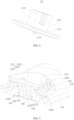
- the clamping base 240 further includes a semi-fixing sleeve 240 and a fastening strip 250.
- the semi-fixing sleeve 240 is fixedly connected with a rear side of the main base body 210, and one end of the fastening strip 250 is connected with one end of the semi-fixing sleeve 240. And another end of the fastening strip 250 is detachably connected with another end of the semi-fixing sleeve 240.
- the semi-fixing sleeve 240 may be sleeved on a tubular component, a columnar component or a rod component, and an inner contour of the cross section of the semi-fixing sleeve 240 matches a shape of the tubular component, the columnar component or the rod component. Then the semi-fixing sleeve 240 is fixed on the tubular component, the columnar component or the rod component through the fastening strip 250 to fix the clamping base 200.
- tightness is adjusted by the fastening strip 250.
- the clamping base 200 includes two hanging lugs, and the two hanging lugs respectively connected with two opposite sides of the main base body 210.
- a hanging hole is formed on each of the hanging lugs so that a strap penetrates the hanging hole. Then the clamping base 200 is realized to fix on the tubular component, the columnar component or the rod component.
Landscapes
- Engineering & Computer Science (AREA)
- General Engineering & Computer Science (AREA)
- Mechanical Engineering (AREA)
- Signal Processing (AREA)
- Connection Of Plates (AREA)
- Telephone Set Structure (AREA)
- Casings For Electric Apparatus (AREA)
- Clamps And Clips (AREA)
Claims (9)
- Stützvorrichtung, die einen Befestigungsrahmen (100) und eine Klemmbasis (200) aufweist;wobei der Befestigungsrahmen einen Hauptrahmenkörper (110) und eine Verbindungsstruktur (120) aufweist, elektronische Produkte an einer Vorderseite des Hauptrahmenkörpers angebracht sind und die Verbindungsstruktur mit einer Rückseite des Hauptrahmenkörpers verbunden ist; undwobei die Verbindungsstruktur lösbar mit der Klemmbasis verbunden ist; wenn die Verbindungsstruktur lösbar mit der Klemmbasis verbunden ist, ist die Verbindungsstruktur so angepasst, dass sie Positionen einstellen kann, und entsprechend der Klemmbasis festgeklemmt ist, wobei die Klemmbasis einen Hauptbasiskörper (210) aufweist; der Hauptbasiskörper einen Übertragungshohlraum (201), eine Einsteckschnittstelle (202) und eine Übertragungsschnittstelle (203) aufweist; die Einsteckschnittstelle und die Übertragungsschnittstelle mit dem Übertragungshohlraum in Verbindung stehen und die Einsteckschnittstelle mit der Übertragungsschnittstelle in Verbindung steht;wobei die Verbindungsstruktur einen Vorsprung (121) aufweist; ein Ende des Vorsprungs mit einer hinteren seitlichen Oberfläche des Hauptrahmenkörpers verbunden ist und sich ein anderes Ende des Vorsprungs in Richtung einer Position weit weg von dem Hauptrahmenkörper erstreckt; eine äußere Kontur eines Querschnitts des Vorsprungs ein Oval mit langen Streifen ist; zwei Ebenen (1211), die einander gegenüberliegen, und zwei bogenförmige Oberflächen (1212), die einander gegenüberliegen, an einer Außenseite des Vorsprungs angeordnet sind; unddie Verbindungsstruktur einen begrenzenden Bestandteil (122) aufweist; ein Ende des begrenzenden Bestandteils mit dem Vorsprung verbunden ist;wenn die Verbindungsstruktur auf dem Hauptbasiskörper angeordnet ist, zeigt eine der bogenförmigen Oberflächen des Vorsprungs direkt zur Einsteckschnittstelle und wird seitlich durch die Einsteckschnittstelle in die Übertragungsschnittstelle eingesetzt; in diesem Moment sich ein anderes Ende des begrenzenden Bestandteils in dem Übertragungshohlraum befindet und in die Übertragungsschnittstelle eingespannt ist; wenn die Verbindungsstruktur auf dem Hauptbasiskörper angeordnet ist, ist die Verbindungsstruktur so angepasst, dass sie sich entsprechend dem Hauptbasiskörper dreht, so dass die Einsteckschnittstelle einer der Ebenen zugewandt ist, wobei der Hauptbasiskörper ferner einen Gleitverbindungskanal (204) und eine Gleitschnittstelle (205) aufweist; die Gleitschnittstelle mit der Übertragungsschnittstelle in Verbindung steht und sich die Gleitschnittstelle und die Übertragungsschnittstelle an einer Vorderseite des Hauptbasiskörpers befinden; der Gleitverbindungskanal mit dem Übertragungshohlraum in Verbindung steht und eine weit vom Übertragungshohlraum entfernte Öffnung des Gleitverbindungskanals die Einsteckschnittstelle ist; die Einsteckschnittstelle mit der Gleitschnittstelle in Verbindung steht; undwenn die Verbindungsstruktur in den Hauptbasiskörper eingesetzt wird, zeigt eine der bogenförmigen Oberflächen des Vorsprungs direkt zur Einsteckschnittstelle und wird seitlich durch die Einsteckschnittstelle in die Gleitschnittstelle eingesetzt; in diesem Moment sich ein begrenzendes Ende des begrenzenden Bestandteils am Gleitverbindungskanal befindet und in die Gleitschnittstelle eingeklemmt wird, wobei der begrenzende Bestandteil eine Begrenzungsplatte (1221) und mindestens zwei Klemmstifte (1222) aufweist, wobei ein Ende jedes der Klemmstifte mit einer Plattenoberfläche der Begrenzungsplatte verbunden ist und jeder der Klemmstifte umfangsmäßig gleichmäßig um eine Mittellinie der Begrenzungsplatte verteilt ist;ein Klemmloch (101) am Befestigungsrahmen ausgebildet ist, und sich das Klemmloch von einer Endfläche des Vorsprungs zu einer vorderen seitlichen Oberfläche des Hauptrahmenkörpers erstreckt; undder Befestigungsrahmen ferner einen Klemmring (133) aufweist, der Klemmring umfangsmäßig an einer Lochwand des Klemmlochs angeordnet ist und jeder der Klemmstifte durch das Klemmloch des Vorsprungs in den Klemmring eingesetzt wird und in dem Klemmring klemmt, wobei der Befestigungsrahmen ferner einen Einbettungsbestandteil (130) aufweist und ein durchdringendes Einbettungsloch (1301) mit Vorder- und Rückseite an dem Einbettungsbestandteil angeordnet ist; der Einbettungsbestandteil in den Befestigungsrahmen eingebettet ist und eine Mittellinie des Klemmlochs auch eine Mittellinie des Einbettungslochs ist, wobei der Einbettungsbestandteil einen Einbettungstisch (131) mit dem Einbettungsloch und eine Einbettungsplatte (132) aufweist, die von einer Umfangsseitenwand des Einbettungstisches divergiert; die Einbettungsplatte mindestens eine Stufe aufweist und in den Hauptrahmenkörper eingebettet ist, und der Einbettungstisch in den Vorsprung eingebettet ist,dadurch gekennzeichnet, dass der Einbettungsbestandteil ferner einen Einbettungsring aufweist, wobei der Einbettungsring mit einem vorderen Ende des Einbettungstisches verbunden ist; der Einbettungsring sich in Richtung des Klemmlochs erstreckt und der Einbettungsring der Klemmring ist.
- Stützvorrichtung nach Anspruch 1, wobei der begrenzende Bestandteil ferner einen Positionierungsvorsprung (1223) aufweist, der Positionierungsvorsprung mit einer Plattenoberfläche der Begrenzungsplatte verbunden ist und die Plattenoberfläche der Begrenzungsplatte jedem der Klemmstifte gegenüberliegt;die Klemmbasis ferner einen Positioniertisch (220) aufweist, der Positioniertisch an einer Hohlraumwand des Übertragungshohlraums befestigt ist, die Hohlraumwand der Übertragungsschnittstelle zugewandt ist, und eine Positionierungsnut (207) auf dem Positioniertisch angeordnet ist; undwenn die Verbindungsstruktur auf dem Hauptbasiskörper angeordnet ist, wird der Positionierungsvorsprung in die Positionierungsnut eingesetzt.
- Stützvorrichtung nach Anspruch 2, wobei eine Oberfläche, die der Einsteckschnittstelle des Positioniertisches zugewandt ist, eine geneigte Führungsfläche (208) ist und die geneigte Führungsfläche in Richtung einer Befestigungsrichtung der Verbindungsstruktur geneigt ist.
- Stützvorrichtung nach Anspruch 1, wobei die Verbindungsstruktur ferner einen ringförmigen begrenzenden Tisch (123) und eine Vielzahl streifenförmiger begrenzender Zähne (124) aufweist; ein Ende des ringförmigen begrenzenden Tisches mit der hinteren seitlichen Oberfläche des Hauptrahmenkörpers verbunden ist und sich ein anderes Ende des ringförmigen begrenzenden Tisches in Richtung der Position weit weg vom Hauptrahmenkörper erstreckt; die Vielzahl der streifenförmigen begrenzenden Zähne mit einer hinteren Oberfläche des ringförmigen begrenzenden Tisches verbunden ist; der ringförmige begrenzende Tisch auf einem Umfang des Vorsprungs aufgesetzt ist, und eine Höhe des ringförmigen begrenzenden Tisches kleiner als eine Höhe des Vorsprungs ist; die Verlängerungslinien jedes der streifenförmigen begrenzenden Zähne eine Mittellinie des Vorsprungs schneiden, und die Verlängerungslinien jedes der streifenförmigen begrenzenden Zähne umfangsmäßig beabstandet und gleichmäßig um die Mittellinie des Vorsprungs angeordnet sind;die Klemmbasis ferner eine Vielzahl streifenförmiger Klemmzähne (230) aufweist, wobei die Vielzahl der streifenförmigen Klemmzähne mit einer vorderen seitlichen Oberfläche des Hauptbasiskörpers verbunden ist; die Verlängerungslinien jedes der streifenförmigen Klemmzähne eine Mittellinie der Übertragungsschnittstelle schneiden, und die Verlängerungslinien jedes der streifenförmigen Klemmzähne umfangsmäßig beabstandet und gleichmäßig um die Mittellinie der Übertragungsschnittstelle herum angeordnet sind; undwenn die Verbindungsstruktur auf der Klemmbasis angeordnet ist, wird jeder der streifenförmigen begrenzenden Zähne jeweils zwischen zwei benachbarten streifenförmigen Klemmzähnen eingesetzt.
- Stützvorrichtung nach Anspruch 4, wobei die Klemmbasis ferner eine Führungspumpe aufweist und die Führungspumpe mit der vorderen seitlichen Oberfläche des Hauptbasiskörpers verbunden ist;die Verbindungsstruktur ferner einen Abstandsring (125) aufweist; ein Ende des Abstandsrings mit der hinteren seitlichen Oberfläche des Hauptrahmenkörpers verbunden ist, und sich ein anderes Ende des Abstandsrings in Richtung der Position erstreckt, die weit vom Hauptrahmenkörper entfernt ist; der Abstandsring auf einem Umfang des ringförmigen begrenzenden Tisches aufgesetzt ist; eine innere Seitenwand des Abstandsrings, eine äußere Seitenwand des ringförmigen begrenzenden Tisches und eine Oberfläche zwischen der inneren Seitenwand des Abstandsrings und der äußeren Seitenwand des ringförmigen begrenzenden Tisches der hinteren seitlichen Oberfläche des Hauptrahmenkörpers eine ringförmige Führungsnut (1201) bilden; die Mittellinie des Vorsprungs auch eine Mittellinie der ringförmigen Führungsnut ist;eine Kerbe (1202) an einer Position des Abstandsrings ausgebildet ist, die einer der bogenförmigen Oberflächen zugewandt ist; undwenn die Verbindungsstruktur auf der Klemmbasis angeordnet ist, dringt die Führungspumpe durch die Kerbe und wird in die ringförmige Führungsnut eingesetzt, und die Führungspumpe gleitet gerichtet in der ringförmigen Führungsnut.
- Stützvorrichtung nach Anspruch 5, wobei die Verbindungsstruktur ferner eine Vielzahl von Stabilisierungszähnen (126) aufweist, wobei die Vielzahl von Stabilisierungszähnen mit der hinteren seitlichen Oberfläche des Hauptrahmenkörpers verbunden ist; wobei Verlängerungslinien jedes der Stabilisierungszähne die Mittellinie des Vorsprungs schneiden und die Verlängerungslinien jedes der Stabilisierungszähne umfangsmäßig beabstandet und gleichmäßig um die Mittellinie des Vorsprungs angeordnet sind; und
die Führungspumpe zwischen zwei beliebigen benachbarten Stabilisierungszähnen eingesetzt wird. - Stützvorrichtung nach Anspruch 1, wobei der Befestigungsrahmen ferner eine Verpackungsfolie (140) aufweist, eine Verpackungsnut (102) an der vorderen seitlichen Oberfläche des Hauptrahmenkörpers und an einer Umfangsseite einer Lochöffnung des Klemmlochs ausgebildet ist; die Verpackungsfolie an die Verpackungsnut angepasst und an der Verpackungsnut befestigt ist.
- Stützvorrichtung nach Anspruch 1, wobei die Klemmbasis zwei Aufhängeösen aufweist und die beiden Aufhängeösen jeweils mit zwei gegenüberliegenden Seiten des Hauptbasiskörpers verbunden sind; an jeder der Aufhängeösen ein Aufhängeloch ausgebildet ist, so dass ein Gurt durch das Aufhängeloch geführt werden kann.
- Stützvorrichtung nach Anspruch 1, wobei die Klemmbasis ferner eine Halbbefestigungshülse (240) und einen Befestigungsstreifen (250) aufweist; die Halbbefestigungshülse fest mit einer Rückseite des Hauptbasiskörpers verbunden ist; ein Ende des Befestigungsstreifens mit einem Ende der Halbbefestigungshülse verbunden ist; und ein anderes Ende des Befestigungsstreifens lösbar mit einem anderen Ende der Halbbefestigungshülse verbunden ist.
Applications Claiming Priority (1)
| Application Number | Priority Date | Filing Date | Title |
|---|---|---|---|
| PCT/CN2020/097764 WO2021258296A1 (zh) | 2020-06-23 | 2020-06-23 | 一种支架装置 |
Publications (4)
| Publication Number | Publication Date |
|---|---|
| EP4033743A1 EP4033743A1 (de) | 2022-07-27 |
| EP4033743A4 EP4033743A4 (de) | 2023-09-13 |
| EP4033743B1 true EP4033743B1 (de) | 2024-11-13 |
| EP4033743C0 EP4033743C0 (de) | 2024-11-13 |
Family
ID=77558944
Family Applications (1)
| Application Number | Title | Priority Date | Filing Date |
|---|---|---|---|
| EP20941785.6A Active EP4033743B1 (de) | 2020-06-23 | 2020-06-23 | Stützvorrichtung |
Country Status (5)
| Country | Link |
|---|---|
| US (1) | US11115516B1 (de) |
| EP (1) | EP4033743B1 (de) |
| JP (1) | JP7573181B2 (de) |
| KR (1) | KR102636206B1 (de) |
| WO (1) | WO2021258296A1 (de) |
Families Citing this family (3)
| Publication number | Priority date | Publication date | Assignee | Title |
|---|---|---|---|---|
| USD966891S1 (en) * | 2020-12-22 | 2022-10-18 | Shenzhen Zhidawei Technology Co., Ltd. | Bottle holder |
| USD968076S1 (en) * | 2021-04-30 | 2022-11-01 | Dongguan Runbone Technology Co., Ltd | Mobile phone stand |
| USD968077S1 (en) * | 2021-04-30 | 2022-11-01 | Dongguan Runbone Technology Co., Ltd | Mobile phone stand |
Family Cites Families (16)
| Publication number | Priority date | Publication date | Assignee | Title |
|---|---|---|---|---|
| US6874744B2 (en) * | 2002-02-25 | 2005-04-05 | Wacom Co., Ltd. | Stand for supporting a display in multiple orientations and a display used in combination with said stand |
| US20150148102A1 (en) * | 2013-11-25 | 2015-05-28 | Cemal Samsilova | System for mechanically and electrically connecting a mobile device case to different mounts |
| US9845058B2 (en) * | 2014-07-23 | 2017-12-19 | Bracketron, Inc. | Heavy duty magnet mount |
| US20180167498A1 (en) * | 2014-07-31 | 2018-06-14 | Robert A. DRAKOS | Electronic device stand |
| JP6078810B2 (ja) * | 2015-07-09 | 2017-02-15 | 株式会社ユピテル | 取付具 |
| KR101816267B1 (ko) * | 2016-06-23 | 2018-01-08 | 전대형 | 휴대용 전자기기의 액세서리 |
| DE102016116580B4 (de) * | 2016-09-05 | 2019-08-29 | Bury Sp.Z.O.O | Haltersystem für ein elektronisches Gerät |
| CN106764295B (zh) * | 2017-03-22 | 2018-08-31 | 深圳市邻友通科技发展有限公司 | 电动支架 |
| US10550992B2 (en) * | 2017-11-21 | 2020-02-04 | Spigen Korea Co., Ltd. | Vehicle or bike mount for electronic devices |
| CN107770337B (zh) * | 2017-12-02 | 2023-11-03 | 湖南云契金典智能科技有限公司 | 一种智能全自动手机支架及使用方法 |
| CN108347508B (zh) * | 2018-03-27 | 2020-04-17 | 黎鹤 | 车载手机支架 |
| CN208227100U (zh) * | 2018-04-20 | 2018-12-11 | 元红波 | 一种手机卡扣支架 |
| CN108692149B (zh) * | 2018-06-20 | 2024-02-20 | 汉洋(博罗)电子有限公司 | 一种防转动锁定装置 |
| CN208798020U (zh) * | 2018-09-21 | 2019-04-26 | 深圳幻影智能科技有限公司 | 一种重力车载出风口支架 |
| KR102082169B1 (ko) * | 2018-11-30 | 2020-02-27 | 주식회사 상상해 | 거치대겸 셀카봉 |
| CN209545661U (zh) * | 2019-05-09 | 2019-10-25 | 深圳市智达伟科技有限公司 | 一种可以用于支架类产品快捷拆卸与旋转定位的结构 |
-
2020
- 2020-06-23 JP JP2022523618A patent/JP7573181B2/ja active Active
- 2020-06-23 EP EP20941785.6A patent/EP4033743B1/de active Active
- 2020-06-23 KR KR1020227019480A patent/KR102636206B1/ko active Active
- 2020-06-23 WO PCT/CN2020/097764 patent/WO2021258296A1/zh not_active Ceased
- 2020-07-22 US US16/935,228 patent/US11115516B1/en active Active
Also Published As
| Publication number | Publication date |
|---|---|
| KR102636206B1 (ko) | 2024-02-13 |
| US11115516B1 (en) | 2021-09-07 |
| JP2023535852A (ja) | 2023-08-22 |
| EP4033743A1 (de) | 2022-07-27 |
| EP4033743A4 (de) | 2023-09-13 |
| KR20220098375A (ko) | 2022-07-12 |
| JP7573181B2 (ja) | 2024-10-25 |
| WO2021258296A1 (zh) | 2021-12-30 |
| EP4033743C0 (de) | 2024-11-13 |
Similar Documents
| Publication | Publication Date | Title |
|---|---|---|
| EP4033743B1 (de) | Stützvorrichtung | |
| US11796128B1 (en) | Two-in-one multi-functional magnetic bracket | |
| CN102084315B (zh) | 带有支架的电子装置夹持器 | |
| US9511903B2 (en) | Covering, protecting, and positioning a portable electronic device | |
| US20130001393A1 (en) | Support mechanism | |
| TW201348626A (zh) | 支撐結構 | |
| WO2016004742A1 (zh) | 多功能可调平板电脑车载支架 | |
| CN204187219U (zh) | 行动装置支架的快拆组件 | |
| WO2022028294A1 (zh) | 一种夹持装置及支架 | |
| TWI511564B (zh) | Flat support system for flat panel display devices | |
| CN216813480U (zh) | 一种夹持装置及支架 | |
| WO2019041189A1 (zh) | 一种手机支架 | |
| KR20180060460A (ko) | 자전거 거치기능을 갖는 셀카봉 | |
| KR101301722B1 (ko) | 휴대기기용 스탠딩장치 | |
| CN103115331B (zh) | 灯具 | |
| KR102148614B1 (ko) | 각도 조절형 노트북 커버 겸용 노트북 받침대 | |
| CN209845257U (zh) | 一种耳机支架及头戴式耳机 | |
| CN221748447U (zh) | 夹持式支架 | |
| KR0156235B1 (ko) | 낚시대의 고정구 일체형 받침대 | |
| CN221569934U (zh) | 一种用于移动终端的固定支架 | |
| CN223402512U (zh) | 一种多功能手机壳 | |
| CN220891689U (zh) | 一种支撑架 | |
| CN219437035U (zh) | 一种电子设备支架及其电子设备保护壳 | |
| CN222746937U (zh) | 一种支架的连接卡位结构 | |
| CN223472289U (zh) | 一种电子设备保护壳 |
Legal Events
| Date | Code | Title | Description |
|---|---|---|---|
| STAA | Information on the status of an ep patent application or granted ep patent |
Free format text: STATUS: THE INTERNATIONAL PUBLICATION HAS BEEN MADE |
|
| PUAI | Public reference made under article 153(3) epc to a published international application that has entered the european phase |
Free format text: ORIGINAL CODE: 0009012 |
|
| STAA | Information on the status of an ep patent application or granted ep patent |
Free format text: STATUS: REQUEST FOR EXAMINATION WAS MADE |
|
| 17P | Request for examination filed |
Effective date: 20220419 |
|
| AK | Designated contracting states |
Kind code of ref document: A1 Designated state(s): AL AT BE BG CH CY CZ DE DK EE ES FI FR GB GR HR HU IE IS IT LI LT LU LV MC MK MT NL NO PL PT RO RS SE SI SK SM TR |
|
| RIC1 | Information provided on ipc code assigned before grant |
Ipc: F16M 13/00 20060101ALI20230510BHEP Ipc: F16M 11/10 20060101ALI20230510BHEP Ipc: F16M 11/04 20060101ALI20230510BHEP Ipc: B60R 11/02 20060101ALI20230510BHEP Ipc: H04M 1/04 20060101AFI20230510BHEP |
|
| A4 | Supplementary search report drawn up and despatched |
Effective date: 20230817 |
|
| RIC1 | Information provided on ipc code assigned before grant |
Ipc: F16M 13/00 20060101ALI20230810BHEP Ipc: F16M 11/10 20060101ALI20230810BHEP Ipc: F16M 11/04 20060101ALI20230810BHEP Ipc: B60R 11/02 20060101ALI20230810BHEP Ipc: H04M 1/04 20060101AFI20230810BHEP |
|
| DAV | Request for validation of the european patent (deleted) | ||
| DAX | Request for extension of the european patent (deleted) | ||
| STAA | Information on the status of an ep patent application or granted ep patent |
Free format text: STATUS: EXAMINATION IS IN PROGRESS |
|
| 17Q | First examination report despatched |
Effective date: 20240327 |
|
| GRAP | Despatch of communication of intention to grant a patent |
Free format text: ORIGINAL CODE: EPIDOSNIGR1 |
|
| STAA | Information on the status of an ep patent application or granted ep patent |
Free format text: STATUS: GRANT OF PATENT IS INTENDED |
|
| INTG | Intention to grant announced |
Effective date: 20240717 |
|
| GRAS | Grant fee paid |
Free format text: ORIGINAL CODE: EPIDOSNIGR3 |
|
| GRAJ | Information related to disapproval of communication of intention to grant by the applicant or resumption of examination proceedings by the epo deleted |
Free format text: ORIGINAL CODE: EPIDOSDIGR1 |
|
| GRAL | Information related to payment of fee for publishing/printing deleted |
Free format text: ORIGINAL CODE: EPIDOSDIGR3 |
|
| STAA | Information on the status of an ep patent application or granted ep patent |
Free format text: STATUS: EXAMINATION IS IN PROGRESS |
|
| GRAP | Despatch of communication of intention to grant a patent |
Free format text: ORIGINAL CODE: EPIDOSNIGR1 |
|
| STAA | Information on the status of an ep patent application or granted ep patent |
Free format text: STATUS: GRANT OF PATENT IS INTENDED |
|
| GRAA | (expected) grant |
Free format text: ORIGINAL CODE: 0009210 |
|
| STAA | Information on the status of an ep patent application or granted ep patent |
Free format text: STATUS: THE PATENT HAS BEEN GRANTED |
|
| INTC | Intention to grant announced (deleted) | ||
| INTG | Intention to grant announced |
Effective date: 20241004 |
|
| AK | Designated contracting states |
Kind code of ref document: B1 Designated state(s): AL AT BE BG CH CY CZ DE DK EE ES FI FR GB GR HR HU IE IS IT LI LT LU LV MC MK MT NL NO PL PT RO RS SE SI SK SM TR |
|
| REG | Reference to a national code |
Ref country code: GB Ref legal event code: FG4D |
|
| REG | Reference to a national code |
Ref country code: CH Ref legal event code: EP |
|
| REG | Reference to a national code |
Ref country code: DE Ref legal event code: R096 Ref document number: 602020041506 Country of ref document: DE |
|
| REG | Reference to a national code |
Ref country code: IE Ref legal event code: FG4D |
|
| U01 | Request for unitary effect filed |
Effective date: 20241113 |
|
| U07 | Unitary effect registered |
Designated state(s): AT BE BG DE DK EE FI FR IT LT LU LV MT NL PT RO SE SI Effective date: 20241119 |
|
| PG25 | Lapsed in a contracting state [announced via postgrant information from national office to epo] |
Ref country code: HR Free format text: LAPSE BECAUSE OF FAILURE TO SUBMIT A TRANSLATION OF THE DESCRIPTION OR TO PAY THE FEE WITHIN THE PRESCRIBED TIME-LIMIT Effective date: 20241113 Ref country code: IS Free format text: LAPSE BECAUSE OF FAILURE TO SUBMIT A TRANSLATION OF THE DESCRIPTION OR TO PAY THE FEE WITHIN THE PRESCRIBED TIME-LIMIT Effective date: 20250313 |
|
| PG25 | Lapsed in a contracting state [announced via postgrant information from national office to epo] |
Ref country code: ES Free format text: LAPSE BECAUSE OF FAILURE TO SUBMIT A TRANSLATION OF THE DESCRIPTION OR TO PAY THE FEE WITHIN THE PRESCRIBED TIME-LIMIT Effective date: 20241113 |
|
| PG25 | Lapsed in a contracting state [announced via postgrant information from national office to epo] |
Ref country code: NO Free format text: LAPSE BECAUSE OF FAILURE TO SUBMIT A TRANSLATION OF THE DESCRIPTION OR TO PAY THE FEE WITHIN THE PRESCRIBED TIME-LIMIT Effective date: 20250213 |
|
| PG25 | Lapsed in a contracting state [announced via postgrant information from national office to epo] |
Ref country code: GR Free format text: LAPSE BECAUSE OF FAILURE TO SUBMIT A TRANSLATION OF THE DESCRIPTION OR TO PAY THE FEE WITHIN THE PRESCRIBED TIME-LIMIT Effective date: 20250214 |
|
| PG25 | Lapsed in a contracting state [announced via postgrant information from national office to epo] |
Ref country code: PL Free format text: LAPSE BECAUSE OF FAILURE TO SUBMIT A TRANSLATION OF THE DESCRIPTION OR TO PAY THE FEE WITHIN THE PRESCRIBED TIME-LIMIT Effective date: 20241113 |
|
| PG25 | Lapsed in a contracting state [announced via postgrant information from national office to epo] |
Ref country code: RS Free format text: LAPSE BECAUSE OF FAILURE TO SUBMIT A TRANSLATION OF THE DESCRIPTION OR TO PAY THE FEE WITHIN THE PRESCRIBED TIME-LIMIT Effective date: 20250213 |
|
| PG25 | Lapsed in a contracting state [announced via postgrant information from national office to epo] |
Ref country code: SM Free format text: LAPSE BECAUSE OF FAILURE TO SUBMIT A TRANSLATION OF THE DESCRIPTION OR TO PAY THE FEE WITHIN THE PRESCRIBED TIME-LIMIT Effective date: 20241113 |
|
| PGFP | Annual fee paid to national office [announced via postgrant information from national office to epo] |
Ref country code: GB Payment date: 20250612 Year of fee payment: 6 |
|
| U20 | Renewal fee for the european patent with unitary effect paid |
Year of fee payment: 6 Effective date: 20250612 |
|
| PG25 | Lapsed in a contracting state [announced via postgrant information from national office to epo] |
Ref country code: SK Free format text: LAPSE BECAUSE OF FAILURE TO SUBMIT A TRANSLATION OF THE DESCRIPTION OR TO PAY THE FEE WITHIN THE PRESCRIBED TIME-LIMIT Effective date: 20241113 |
|
| PG25 | Lapsed in a contracting state [announced via postgrant information from national office to epo] |
Ref country code: CZ Free format text: LAPSE BECAUSE OF FAILURE TO SUBMIT A TRANSLATION OF THE DESCRIPTION OR TO PAY THE FEE WITHIN THE PRESCRIBED TIME-LIMIT Effective date: 20241113 |
|
| PLBE | No opposition filed within time limit |
Free format text: ORIGINAL CODE: 0009261 |
|
| STAA | Information on the status of an ep patent application or granted ep patent |
Free format text: STATUS: NO OPPOSITION FILED WITHIN TIME LIMIT |
|
| 26N | No opposition filed |
Effective date: 20250814 |