EP4033482A1 - Vorrichtung zur schallanpassung in fahrzeuginnenraum - Google Patents
Vorrichtung zur schallanpassung in fahrzeuginnenraum Download PDFInfo
- Publication number
- EP4033482A1 EP4033482A1 EP21212453.1A EP21212453A EP4033482A1 EP 4033482 A1 EP4033482 A1 EP 4033482A1 EP 21212453 A EP21212453 A EP 21212453A EP 4033482 A1 EP4033482 A1 EP 4033482A1
- Authority
- EP
- European Patent Office
- Prior art keywords
- sound
- vehicle
- startup
- interior
- accessory
- Prior art date
- Legal status (The legal status is an assumption and is not a legal conclusion. Google has not performed a legal analysis and makes no representation as to the accuracy of the status listed.)
- Pending
Links
- 230000000873 masking effect Effects 0.000 claims abstract description 53
- 230000001186 cumulative effect Effects 0.000 claims description 13
- 230000015556 catabolic process Effects 0.000 description 4
- 238000006731 degradation reaction Methods 0.000 description 4
- 238000000034 method Methods 0.000 description 3
- 230000032683 aging Effects 0.000 description 2
- 238000010586 diagram Methods 0.000 description 2
- 230000000694 effects Effects 0.000 description 2
- 239000004973 liquid crystal related substance Substances 0.000 description 2
- 206010016322 Feeling abnormal Diseases 0.000 description 1
- 230000033764 rhythmic process Effects 0.000 description 1
- 238000004088 simulation Methods 0.000 description 1
Images


Classifications
-
- G—PHYSICS
- G10—MUSICAL INSTRUMENTS; ACOUSTICS
- G10K—SOUND-PRODUCING DEVICES; METHODS OR DEVICES FOR PROTECTING AGAINST, OR FOR DAMPING, NOISE OR OTHER ACOUSTIC WAVES IN GENERAL; ACOUSTICS NOT OTHERWISE PROVIDED FOR
- G10K11/00—Methods or devices for transmitting, conducting or directing sound in general; Methods or devices for protecting against, or for damping, noise or other acoustic waves in general
- G10K11/16—Methods or devices for protecting against, or for damping, noise or other acoustic waves in general
- G10K11/175—Methods or devices for protecting against, or for damping, noise or other acoustic waves in general using interference effects; Masking sound
- G10K11/1752—Masking
Definitions
- the present invention relates to a vehicle-interior sound-adjustment apparatus configured to be able to suppress an operating sound of an accessory in a vehicle interior from being heard by an occupant in the vehicle interior.
- an accessory having a drive mechanism configured to operate by driving a motor, a gear, and the like may be installed.
- the accessory include a head-up display (HUD) device.
- the HUD device causes visible light emitted from a liquid crystal display (LCD) to be reflected by a reflecting mirror, and then projects the reflected visible light on a display panel of the HUD device, a windshield external to the HUD device, and the like such that an occupant in the vehicle interior can visually recognize the visible light as an image.
- the HUD device as described above includes a drive mechanism configured to drive the reflecting mirror, the display panel, and the like.
- an operating sound of the drive mechanism may give discomfort and a strange feeling to the occupant in the vehicle interior.
- Examples of the operating sound of the drive mechanism that may give discomfort and a strange feeling to the occupant include motor sounds and engagement sounds of gears. Therefore, various vehicle-interior sound-adjustment apparatuses have been proposed in order to suppress such an operating sound of the drive mechanism being heard by the occupant.
- One example of the vehicle-interior sound-adjustment apparatus is an HUD device having a Helmholtz resonator (for example, see Patent Literature 1).
- the Helmholtz resonator used in the one example of the vehicle-interior sound-adjustment apparatus described above can merely suppress the operating sound of the accessory having a peak of the sound pressure level in a predefined fixed resonance frequency.
- the resonance frequency of the operating sound generated in the accessory such as the HUD device may change due to the temperature environment around the accessory, degradation of the accessory over time, and the like. Therefore, in the one example of the vehicle-interior sound-adjustment apparatus, it is impossible to efficiently suppress the operating sound of the accessory being heard by the occupant in a case in which the operating sound of the accessory changes, for example.
- an vehicle-interior sound-adjustment apparatus configured to be able to suppress an operating sound of an accessory provided in a vehicle interior of a vehicle being heard by an occupant in the vehicle interior, the vehicle-interior sound-adjustment apparatus including: a sound output unit configured to be able to output a sound to the vehicle interior; a masking sound generation unit configured to be able to generate a masking sound for masking the operating sound of the accessory; a startup sound generation unit configured to be able to generate a startup sound emitted at time of startup of the vehicle; and a control unit configured to cause the startup sound generated by the startup sound generation unit to be output from the sound output unit.
- the startup sound generation unit is configured to generate a first startup sound composed of a first sound, and a second startup sound composed of a second sound having a higher frequency than the first sound, and the masking sound generated by the masking sound generation unit
- the control unit is configured to cause the first startup sound generated by the startup sound generation unit to be output from the sound output unit in a state in which the accessory is set so as not to perform an operation that emits the operating sound, and is configured to cause the second startup sound generated by the startup sound generation unit to be output from the sound output unit in a state in which the accessory is set to perform an operation that emits the operating sound.
- the vehicle-interior sound-adjustment apparatus it is possible to efficiently suppress the operating sound of the accessory being heard by an occupant while suppressing discomfort and a strange feeling of the occupant.
- a vehicle-interior sound-adjustment apparatus is described together with a vehicle in which the vehicle-interior sound-adjustment apparatus is mounted.
- the vehicle in which the vehicle-interior sound-adjustment apparatus according to the embodiment is mounted is an automobile having a vehicle interior space.
- the vehicle can be a vehicle other than the automobile having a vehicle interior space.
- a vehicle front side and a vehicle rear side are indicated by a one-headed arrow F and a one-headed arrow B, respectively.
- a left side and a right side when facing the vehicle front side are indicated by a one-headed arrow L and a one-headed arrow R, respectively.
- a vehicle width direction is indicated by the one-headed arrow L and the one-headed arrow R.
- a vehicle upper side and a vehicle lower side are indicated by a one-headed arrow U and a one-headed arrow D, respectively.
- the vehicle-interior sound-adjustment apparatus 10 and the vehicle 1 according to the embodiment are generally configured as follows. Referring to Figure 1 to Figure 3 , the vehicle-interior sound-adjustment apparatus 10 is configured to be able to suppress or reduce an operating sound of an accessory 20 provided in a vehicle interior 2 of the vehicle 1 being heard by an occupant in the vehicle interior 2.
- the accessory 20 provided in the vehicle interior 2 of the vehicle 1 has a drive mechanism 21 configured to operate by driving a motor, a gear, and the like.
- the accessory 20 is a head-up display (HUD) device 20 as one example.
- the accessory is not limited to the HUD device.
- the accessory can also be an electric tilt and telescopic steering, an electric power seat, or an automotive navigation system with a drivable display.
- the vehicle-interior sound-adjustment apparatus 10 includes a sound output unit 11 configured to output sound to the vehicle interior 2. As illustrated in Figure 1 , the vehicle-interior sound-adjustment apparatus 10 includes a masking sound generation unit 12 configured to generate a masking sound for masking the operating sound of the HUD device 20. The vehicle-interior sound-adjustment apparatus 10 includes a startup sound generation unit 13 configured to generate a startup sound emitted at the time of startup of the vehicle 1. The vehicle-interior sound-adjustment apparatus 10 includes a control unit 14 configured to cause the startup sound generated by the startup sound generation unit 13 to be output from the sound output unit 11.
- the startup sound generation unit 13 is configured to be able to generate a first startup sound and a second startup sound.
- the first startup sound is composed of a first sound.
- the second startup sound is composed of a second sound, which is a sound of a higher frequency or pitch than the first sound, and the masking sound generated by the masking sound generation unit 12.
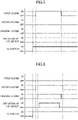
- a horizontal axis X indicates a sound range or a frequency (kHz).
- a sound range of the first sound in other words, a frequency band in which a sound pressure level (dB) of the first sound is higher than in other frequency ranges is indicated by a double-headed arrow P1.
- a sound range of the second sound in other words, a frequency band in which a sound pressure level of the second sound is higher than in other frequency ranges is indicated by a double-headed arrow P2.
- a sound range of the masking sound in other words, a frequency band in which a sound pressure level of the masking sound is higher than in other frequency ranges is indicated by a double-headed arrow Q.
- a sound range of the operating sound of the HUD device 20 in other words, a frequency band in which a sound pressure level of the operating sound of the HUD device 20 is higher than that of other frequency ranges is indicated by a double-headed arrow M.
- control unit 14 is configured to cause the first startup sound generated by the startup sound generation unit 13 to be output from the sound output unit 11 in a state in which the HUD device 20 is set so as not to activate an operation that emits an operating sound (hereinafter referred to as a "non-operation setting state" as necessary).
- control unit 14 is configured to cause the second startup sound generated by the startup sound generation unit 13 to be output from the sound output unit 11 in a state in which the HUD device 20 is set to perform an operation that emits an operating sound (hereinafter referred to as an "operation setting state" as necessary).
- the masking sound generation unit 12 can be configured to adjust the frequency at the peak of the sound pressure level of the masking sound in accordance with the cumulative number of operations of the HUD device 20.
- the vehicle 1 can be configured in detail as follows.
- the vehicle 1 includes an instrument panel 3 disposed at the front side of the vehicle interior 2 of the vehicle 1.
- the vehicle 1 includes a driver's seat 4a and a passenger seat 4b disposed on the rear side with respect to the instrument panel 3.
- the driver's seat 4a and the passenger seat 4b are disposed side by side in the vehicle width direction.
- the driver's seat 4a and the passenger seat 4b form a front-row seat group 4.
- the vehicle 1 includes at least one rear-row seat group 5 disposed on the rear side with respect to the front-row seat group 4.
- the rear-row seat group 5 is formed of a plurality of rear seats 5a and 5b.
- the vehicle 1 includes one rear-row seat group 5 formed of two rear seats 5a and 5b.
- the vehicle can include one rear-row seat group formed of three or more rear seats.
- the vehicle can also be formed of two or more rear-row seat groups formed of a plurality of rear seats and spaced apart from each other in the front-rear direction.
- the vehicle 1 includes an ignition switch (hereinafter referred to as an "IG switch" as necessary) 6 for starting up the vehicle 1.
- IG switch an ignition switch
- a driving source such as an engine, a travel driving motor, or the like starts up.
- the driving source and the like stop.
- the HUD device 20 can be configured in detail as follows. As illustrated in Figure 2 , the HUD device 20 is disposed on an upper surface portion 3a of the instrument panel 3 close to the driver's seat 4a in the vehicle width direction. As illustrated in Figure 1 and Figure 3 , the HUD device 20 includes a display panel 22 configured to be movable in the up-down direction between a deployed state and a stored state. In Figure 3 , the display panel 22 in the deployed state is indicated by a solid line, and the display panel 22 in the stored state is indicated by a virtual line.
- the display panel 22 is configured to be able to reflect light while being able to transmit light.
- the display panel 22 in the deployed state is disposed so as to face the driver's seat 4a in the front-rear direction.
- the driver can visually recognize a display projected on the display panel 22 in the deployed state while visually recognizing scenery located behind the display panel 22 in the deployed state.
- the HUD device 20 includes a liquid crystal display (LCD) 23 configured to be able to forms a display image projected on the display panel 22.
- the HUD device 20 includes a reflecting mirror 24 configured to reflect the display image from the LCD 23 toward the display panel 22.
- a projection path (indicated by a one-headed arrow K in Figure 3 ) heading toward the display panel 22 from the LCD 23 via the reflecting mirror 24 is formed.
- the HUD device 20 includes a casing 25 that houses the display panel 22 in the stored state, the LCD 23, and the reflecting mirror 24.
- the casing 25 has an opening 25a formed in an upper portion of the casing 25 such that the display panel 22 and the projection path can pass therethrough.
- the drive mechanism 21 of the HUD device 20 includes a motor 21a, and a leadscrew 21b that is turnable by driving of the motor 21a. As shown by a double-headed arrow H (illustrated in Figure 3 ), the display panel 22 moves in the up-down direction between the deployed state and the stored state in accordance with turning of the leadscrew 21b.
- the operating sound of the HUD device 20 is generated by the driving of the motor 21a of the drive mechanism 21, the turning of the leadscrew 21b of the drive mechanism 21, and the like.
- the drive mechanism can also be configured to be able to adjust an angle of reflection at the reflecting mirror by a motor, a gear, and the like. In this case, an operating sound may be generated when the angle of reflection at the reflecting mirror is adjusted.
- An operation of the HUD device 20 is a deploying operation that moves the display panel 22 from the stored state to the deployed state.
- the HUD device 20 includes an operation switching unit 27 configured to perform switching between the non-operation setting state and the operation setting state.
- the HUD device 20 starts an operation that emits an operating sound at the same time as the IG switch 6 is switched to the ON state from the OFF state or after a predetermined amount of time elapses from the switching to the ON state.
- the HUD device 20 starts the deploying operation of the display panel 22 at the same time as the IG switch 6 is switched to the ON state from the OFF state or after a predetermined amount of time elapses from the switching to the ON state.
- the HUD device 20 ends the deploying operation when the display panel 22 is placed in the deployed state.
- the HUD device can also start the deploying operation of the display panel at the same time as the occupant such as the driver performs operation of switching the operation switching unit from the non-operation setting state to the operation setting state after the IG switch 6 is switched to the ON state from the OFF state.
- the vehicle-interior sound-adjustment apparatus 10 can be configured in detail as follows.
- the sound output unit 11 of the vehicle-interior sound-adjustment apparatus 10 includes a plurality of speakers 11a, 11b, 11c, and 11d.
- the sound output unit 11 can include the first speaker 11a located on the outer side with respect to the driver's seat 4a in the vehicle width direction.
- the sound output unit 11 can include the second speaker 11b located on the outer side with respect to the passenger seat 4b in the vehicle width direction.
- the sound output unit 11 can include the third speaker 11c located on one side with respect to the rear-row seat group 5 in the vehicle width direction.
- the sound output unit 11 can include the fourth speaker 11d located on the other side with respect to the rear-row seat group 5 in the vehicle width direction.
- the masking sound generation unit 12, the startup sound generation unit 13, and the control unit 14 of the vehicle-interior sound-adjustment apparatus 10 can each be configured to include electronic components such as a central processing unit (CPU), a random access memory (RAM), a read only memory (ROM), a flash memory, an input interface, and an output interface, and an electric circuit in which the electronic components are disposed.
- the ROM can store various control constants, various maps, programs for executing various controls, and the like therein.
- one electric control unit (ECU) 15 can include the masking sound generation unit 12, the startup sound generation unit 13, and the control unit 14 of the vehicle-interior sound-adjustment apparatus 10.
- the masking sound generation unit, the startup sound generation unit, and the control unit are not limited to the above.
- the masking sound generation unit, the startup sound generation unit, and the control unit can be included in different ECUs.
- One of the masking sound generation unit, the startup sound generation unit, and the control unit can also be included in an ECU different from an ECU including the rest of the units.
- the masking sound generation unit 12 is configured to be able to count the cumulative number of operations of the HUD device 20.
- the masking sound generation unit 12 is configured to be able to store the cumulative number of operations of the HUD device 20 therein.
- the masking sound generation unit 12 is configured to count the cumulative number of operations of the HUD device 20 by incrementing a cumulative number N of operations of the HUD device 20 stored in a previous operation by 1 every time the HUD device 20 operates, and to store the cumulative number therein.
- the masking sound generation unit 12 is configured to repeat the counting and storage as above at the time of the operation of the HUD device 20.
- the startup sound generation unit 13 is configured to be able to generate a second preliminary startup sound composed of the second sound.
- the sound range of the second sound has higher frequencies than those of the sound range of the first sound. Therefore, the second sound is captured by an ear of the occupant such as the driver more easily than the first sound. It is preferred that the sound pressure level in the sound range of the second sound be greater than the sound pressure level in the sound range of the first sound.
- the sound range of the operating sound of the HUD device 20 is substantially equal to the sound range of the masking sound.
- the sound range of the second sound includes the sound range of the operating sound of the HUD device 20 and the sound range of the masking sound. In other words, the sound range of the operating sound of the HUD device 20 and the sound range of the masking sound are within the sound range of the second sound. It is preferred that the sound pressure level in the sound range of the masking sound be greater than the sound pressure level in the sound range of the operating sound of the HUD device 20.
- Each of the first and second sounds can be music.
- the first sound can be first music
- the second sound can be second music.
- music is defined as something including rhythm, melody, and harmony.
- the control unit 14 is configured to be able to determine whether the IG switch 6 is switched to the ON state from the OFF state.
- the control unit 14 is configured to be able to determine whether the HUD device 20 is in the operation setting state when the IG switch 6 is switched to the ON state from the OFF state.
- the control unit 14 is configured to cause the first startup sound to be output from the sound output unit 11 at the same time as the IG switch 6 is switched from the OFF state to the ON state or after a predetermined amount of time elapses from the switching to the ON state when the HUD device 20 is not in the operation setting state, in other words, when the HUD device 20 is in the non-operation setting state.
- the control unit 14 is configured to cause the second startup sound to be output from the sound output unit 11 in a state in which the HUD device 20 is in the operation setting state and is operating in a manner of emitting an operating sound after the IG switch 6 is switched to the ON state from the OFF state.
- the control unit 14 is configured to end the output of the second startup sound from the sound output unit 11 at the same time as the operation of the HUD device 20 ends, in particular, the deploying operation of the display panel 22 ends or after a predetermined amount of time elapses from the end of the operation.
- the control unit 14 can cause the second preliminary startup sound to be output from the sound output unit 11 between a timing at which the IG switch 6 is switched to the ON state from the OFF state and a timing at which the operation of the HUD device 20 starts.
- the control unit 14 can also cause the second preliminary startup sound to be output from the sound output unit 11 from when the operation of the HUD device 20 ends, in particular, when the deploying operation of the display panel 22 ends until a predetermined amount of time elapses.
- Step S1 a sound adjustment method executed by the vehicle-interior sound-adjustment apparatus 10 according to the embodiment is described.
- the IG switch 6 is in the OFF state (Step S1). It is determined whether the IG switch 6 is switched to the ON state from the OFF state (Step S2). When the IG switch 6 is not switched to the ON state from the OFF state (NO), Step S2 is executed again.
- Step S3 When the IG switch 6 is switched to the ON state from the OFF state (YES), it is determined whether the HUD device 20 is in the operation setting state (Step S3). When the HUD device 20 is not in the operation setting state (NO), in other words, when the HUD device 20 is in the non-operation setting state, the first startup sound is output from the sound output unit 11 (Step S4).
- Step S5 When the HUD device 20 is in the operation setting state (YES), 1 is added to the cumulative number N of operations of the HUD device 20 stored in the previous operation of the HUD device 20, and a latest cumulative number (N+1) of operations of the HUD device 20 is obtained as a result (Step S5).
- the masking sound is corrected or adjusted so as to change the frequency at the peak of the sound pressure level of the masking sound in accordance with the latest cumulative number (N+1) of operations of the HUD device 20 (Step S6).
- the masking sound is adjusted so as to respond to degradation over time associated with the increase of the cumulative number of operations of the HUD device 20.
- the relationship between the increase of the cumulative number of operations of the HUD device 20 and the aging degradation can be predefined by experiments, usage results, simulations, and the like.
- the second startup sound composed of the second sound having a higher frequency than the first sound, and the masking sound, which has been corrected in Step S5, is output from the sound output unit 11 (Step S7).
- the vehicle-interior sound-adjustment apparatus 10 is the vehicle-interior sound-adjustment apparatus 10 configured to be able to suppress the operating sound of the accessory 20 provided in the vehicle interior 2 of the vehicle 1 being heard by the occupant in the vehicle interior 2.
- the vehicle-interior sound-adjustment apparatus 10 includes: the sound output unit 11 configured to be able to output a sound to the vehicle interior 2; the masking sound generation unit 12 configured to be able to generate the masking sound for masking the operating sound of the accessory 20; the startup sound generation unit 13 configured to be able to generate the startup sound emitted at the time of startup of the vehicle 1; and the control unit 14 configured to cause the startup sound generated by the startup sound generation unit 13 to be output from the sound output unit 11.
- the startup sound generation unit 13 is configured to be able to generate the first startup sound composed of the first sound, and the second startup sound composed of the second sound having a higher frequency than the first sound, and the masking sound generated by the masking sound generation unit 12, and the control unit 14 is configured to cause the first startup sound generated by the startup sound generation unit 13 to be output from the sound output unit 11 in a state in which the accessory 20 is set so as not to perform an operation that emits the operating sound, and is configured to cause the second startup sound generated by the startup sound generation unit 13 to be output from the sound output unit 11 in a state in which the accessory 20 is set to perform an operation that emits the operating sound.
- the accessory in particular, the HUD device tends to emit an operating sound that is unpleasant for the occupant in the vehicle interior at the time of startup of the vehicle.
- the vehicle-interior sound-adjustment apparatus 10 in particular, as a startup sound which is output from the sound output unit 11 each time the vehicle 1 is started up, the first startup sound composed of the first sound can be used in a state in which the accessory 20 is not operating in a manner in which the operating sound is emitted, and the second startup sound composed of the second sound and the masking sound can be used in a state in which the accessory 20 is operating in a manner in which the operating sound is emitted.
- the second sound of the second startup sound has a higher frequency than the first sound of the first startup sound. Therefore, there is substantially no difference in the frequency between the operating sound of the HUD device 20 and the second startup sound.
- the second startup sound due to a cocktail party effect, it is difficult for the occupant to capture the sound in the frequency band in which the operating sound of the HUD device 20 is produced so that discomfort and a strange feeling to the masking sound felt by the occupant can be suppressed. Therefore, it is possible to efficiently suppress the operating sound of the accessory 20 being heard by the occupant while reducing discomfort and a strange feeling of the occupant.
- the masking sound generation unit 12 is configured to adjust the frequency at the peak of the sound pressure level of the masking sound in accordance with the cumulative number of operations of the accessory 20. Therefore, it is possible to efficiently suppress the operating sound of the accessory 20 being heard by the occupant even when the operating sound of the accessory 20 changes due to aging degradation of the accessory 20.
Landscapes
- Physics & Mathematics (AREA)
- Engineering & Computer Science (AREA)
- Acoustics & Sound (AREA)
- Multimedia (AREA)
- Fittings On The Vehicle Exterior For Carrying Loads, And Devices For Holding Or Mounting Articles (AREA)
- Instrument Panels (AREA)
- Soundproofing, Sound Blocking, And Sound Damping (AREA)
Applications Claiming Priority (1)
| Application Number | Priority Date | Filing Date | Title |
|---|---|---|---|
| JP2021008050A JP2022112282A (ja) | 2021-01-21 | 2021-01-21 | 車室音響調整装置 |
Publications (1)
| Publication Number | Publication Date |
|---|---|
| EP4033482A1 true EP4033482A1 (de) | 2022-07-27 |
Family
ID=78851039
Family Applications (1)
| Application Number | Title | Priority Date | Filing Date |
|---|---|---|---|
| EP21212453.1A Pending EP4033482A1 (de) | 2021-01-21 | 2021-12-06 | Vorrichtung zur schallanpassung in fahrzeuginnenraum |
Country Status (2)
| Country | Link |
|---|---|
| EP (1) | EP4033482A1 (de) |
| JP (1) | JP2022112282A (de) |
Citations (7)
| Publication number | Priority date | Publication date | Assignee | Title |
|---|---|---|---|---|
| JP2005278301A (ja) * | 2004-03-24 | 2005-10-06 | Toyota Motor Corp | ノイズのマスキング方法 |
| US20050261815A1 (en) * | 2004-05-20 | 2005-11-24 | Cowelchuk Glenn A | System for customizing settings and sounds for vehicle |
| US20110282654A1 (en) * | 2010-05-17 | 2011-11-17 | Yohei Takechi | Quality evaluation method and quality evaluation apparatus |
| US20140067217A1 (en) * | 2011-02-18 | 2014-03-06 | Pete Stares | Vehicle and method of controlling a vehicle |
| DE102014220600A1 (de) * | 2014-10-10 | 2016-04-14 | Brose Fahrzeugteile Gmbh & Co. Kommanditgesellschaft, Coburg | Steuergerät, Fahrzeugbaugruppe, Kraftfahrzeug und Verfahren |
| JP2017154712A (ja) | 2016-03-04 | 2017-09-07 | 日本精機株式会社 | ヘッドアップディスプレイ装置 |
| WO2019158387A1 (de) * | 2018-02-16 | 2019-08-22 | Audi Ag | Verfahren zum kaschieren eines geräuschs eines kraftfahrzeugs und kraftfahrzeug |
-
2021
- 2021-01-21 JP JP2021008050A patent/JP2022112282A/ja active Pending
- 2021-12-06 EP EP21212453.1A patent/EP4033482A1/de active Pending
Patent Citations (7)
| Publication number | Priority date | Publication date | Assignee | Title |
|---|---|---|---|---|
| JP2005278301A (ja) * | 2004-03-24 | 2005-10-06 | Toyota Motor Corp | ノイズのマスキング方法 |
| US20050261815A1 (en) * | 2004-05-20 | 2005-11-24 | Cowelchuk Glenn A | System for customizing settings and sounds for vehicle |
| US20110282654A1 (en) * | 2010-05-17 | 2011-11-17 | Yohei Takechi | Quality evaluation method and quality evaluation apparatus |
| US20140067217A1 (en) * | 2011-02-18 | 2014-03-06 | Pete Stares | Vehicle and method of controlling a vehicle |
| DE102014220600A1 (de) * | 2014-10-10 | 2016-04-14 | Brose Fahrzeugteile Gmbh & Co. Kommanditgesellschaft, Coburg | Steuergerät, Fahrzeugbaugruppe, Kraftfahrzeug und Verfahren |
| JP2017154712A (ja) | 2016-03-04 | 2017-09-07 | 日本精機株式会社 | ヘッドアップディスプレイ装置 |
| WO2019158387A1 (de) * | 2018-02-16 | 2019-08-22 | Audi Ag | Verfahren zum kaschieren eines geräuschs eines kraftfahrzeugs und kraftfahrzeug |
Also Published As
| Publication number | Publication date |
|---|---|
| JP2022112282A (ja) | 2022-08-02 |
Similar Documents
| Publication | Publication Date | Title |
|---|---|---|
| US20190215606A1 (en) | Vehicle and method for controlling the same | |
| US20100188204A1 (en) | Display device for vehicle | |
| EP3213949A1 (de) | Blickfeldanzeigevorrichtung | |
| JP2008209724A (ja) | 車両用ヘッドアップディスプレイ装置 | |
| CN110154933B (zh) | 车辆用隔音构造 | |
| JPWO2016017114A1 (ja) | 電子ミラー装置 | |
| JP6471575B2 (ja) | 車両用表示制御装置及び車両用表示ユニット | |
| EP4033482A1 (de) | Vorrichtung zur schallanpassung in fahrzeuginnenraum | |
| WO2017169610A1 (ja) | ヘッドアップディスプレイ装置 | |
| CN108058644B (zh) | 显示装置以及内装部件单元 | |
| JP6925891B2 (ja) | 表示装置、及び、内装部材ユニット | |
| JP2010202100A (ja) | 注意喚起システム | |
| US10698209B2 (en) | Embedded head-up display device | |
| JP5232713B2 (ja) | 車載表示装置 | |
| JP2011097234A (ja) | 携帯機器制御方法および携帯機器 | |
| US20180222385A1 (en) | Heads-up display with point of display audio alert capability | |
| JP6263722B2 (ja) | ヘッドアップディスプレイ装置 | |
| WO2014002710A1 (ja) | 車両用警報装置 | |
| EP3683615A1 (de) | Head-up-display-anzeigevorrichtung für ein fahrzeug sowie fahrzeug | |
| JP7468042B2 (ja) | 表示装置及びヘッドアップディスプレイ | |
| JP6925892B2 (ja) | 表示装置、及び、内装部材ユニット | |
| WO2023248687A1 (ja) | 虚像表示装置 | |
| KR20240083818A (ko) | 정보 처리장치, 표시 시스템, 이동체, 정보 처리방법, 및 기억매체 | |
| CN110816270B (zh) | 显示装置、显示控制方法及存储介质 | |
| JP2018203122A (ja) | 車両用表示装置 |
Legal Events
| Date | Code | Title | Description |
|---|---|---|---|
| PUAI | Public reference made under article 153(3) epc to a published international application that has entered the european phase |
Free format text: ORIGINAL CODE: 0009012 |
|
| STAA | Information on the status of an ep patent application or granted ep patent |
Free format text: STATUS: REQUEST FOR EXAMINATION WAS MADE |
|
| 17P | Request for examination filed |
Effective date: 20211223 |
|
| AK | Designated contracting states |
Kind code of ref document: A1 Designated state(s): AL AT BE BG CH CY CZ DE DK EE ES FI FR GB GR HR HU IE IS IT LI LT LU LV MC MK MT NL NO PL PT RO RS SE SI SK SM TR |
|
| GRAP | Despatch of communication of intention to grant a patent |
Free format text: ORIGINAL CODE: EPIDOSNIGR1 |
|
| STAA | Information on the status of an ep patent application or granted ep patent |
Free format text: STATUS: GRANT OF PATENT IS INTENDED |
|
| RIC1 | Information provided on ipc code assigned before grant |
Ipc: G10K 11/175 20060101AFI20240320BHEP |
|
| INTG | Intention to grant announced |
Effective date: 20240410 |
|
| GRAS | Grant fee paid |
Free format text: ORIGINAL CODE: EPIDOSNIGR3 |
|
| GRAJ | Information related to disapproval of communication of intention to grant by the applicant or resumption of examination proceedings by the epo deleted |
Free format text: ORIGINAL CODE: EPIDOSDIGR1 |
|
| GRAL | Information related to payment of fee for publishing/printing deleted |
Free format text: ORIGINAL CODE: EPIDOSDIGR3 |
|
| STAA | Information on the status of an ep patent application or granted ep patent |
Free format text: STATUS: REQUEST FOR EXAMINATION WAS MADE |
|
| GRAP | Despatch of communication of intention to grant a patent |
Free format text: ORIGINAL CODE: EPIDOSNIGR1 |
|
| STAA | Information on the status of an ep patent application or granted ep patent |
Free format text: STATUS: GRANT OF PATENT IS INTENDED |
|
| INTC | Intention to grant announced (deleted) |