EP4033058A1 - Beschlag zur begrenzung einer öffnungsweite eines gegen einen rahmen schwenkbaren flügels eines fensters - Google Patents
Beschlag zur begrenzung einer öffnungsweite eines gegen einen rahmen schwenkbaren flügels eines fensters Download PDFInfo
- Publication number
- EP4033058A1 EP4033058A1 EP22150852.6A EP22150852A EP4033058A1 EP 4033058 A1 EP4033058 A1 EP 4033058A1 EP 22150852 A EP22150852 A EP 22150852A EP 4033058 A1 EP4033058 A1 EP 4033058A1
- Authority
- EP
- European Patent Office
- Prior art keywords
- fitting
- latching
- slider
- stop
- recess
- Prior art date
- Legal status (The legal status is an assumption and is not a legal conclusion. Google has not performed a legal analysis and makes no representation as to the accuracy of the status listed.)
- Granted
Links
Images



Classifications
-
- E—FIXED CONSTRUCTIONS
- E05—LOCKS; KEYS; WINDOW OR DOOR FITTINGS; SAFES
- E05C—BOLTS OR FASTENING DEVICES FOR WINGS, SPECIALLY FOR DOORS OR WINDOWS
- E05C17/00—Devices for holding wings open; Devices for limiting opening of wings or for holding wings open by a movable member extending between frame and wing; Braking devices, stops or buffers, combined therewith
- E05C17/02—Devices for holding wings open; Devices for limiting opening of wings or for holding wings open by a movable member extending between frame and wing; Braking devices, stops or buffers, combined therewith by mechanical means
- E05C17/04—Devices for holding wings open; Devices for limiting opening of wings or for holding wings open by a movable member extending between frame and wing; Braking devices, stops or buffers, combined therewith by mechanical means with a movable bar or equivalent member extending between frame and wing
- E05C17/12—Devices for holding wings open; Devices for limiting opening of wings or for holding wings open by a movable member extending between frame and wing; Braking devices, stops or buffers, combined therewith by mechanical means with a movable bar or equivalent member extending between frame and wing consisting of a single rod
- E05C17/24—Devices for holding wings open; Devices for limiting opening of wings or for holding wings open by a movable member extending between frame and wing; Braking devices, stops or buffers, combined therewith by mechanical means with a movable bar or equivalent member extending between frame and wing consisting of a single rod pivoted at one end, and with the other end running along a guide member
- E05C17/28—Devices for holding wings open; Devices for limiting opening of wings or for holding wings open by a movable member extending between frame and wing; Braking devices, stops or buffers, combined therewith by mechanical means with a movable bar or equivalent member extending between frame and wing consisting of a single rod pivoted at one end, and with the other end running along a guide member with braking, clamping or securing means at the connection to the guide member
Definitions
- the invention relates to a fitting for limiting an opening width of a sash of a window, a balcony door or the like, which can be pivoted against a frame, with a sash-side fitting arrangement and a frame-side fitting arrangement, with a limiting element connecting the fitting arrangements with one another, one of the fitting arrangements having a stop and one opposite the stop Has latching means for limiting the opening width, wherein in one of the fitting arrangements a slider coupled to the limiting element is guided in a longitudinally displaceable manner and the fitting arrangement guiding the slider has the stop for limiting the range of movement.
- a fitting for limiting the opening width of a sash of a window is known from practice in various embodiments. Limiting the opening width allows ventilation through the window, but prevents further opening, for example for security reasons. However, for cleaning purposes, for example, it is often necessary to fully open the wing.
- An opening-limiting device of the type mentioned is, for example, from EP 3 034 728 A1 known.
- a displaceable adjusting body can be connected to a resilient locking bolt.
- the slider can be moved towards and away from the adjusting body held by the locking bolt.
- the opening-limiting device has a large number of components to be assembled and is complex in construction.
- An opening limit for a fitting is from the EP 2 107 194 A1 known.
- a stop for limiting the opening width is coupled with latching means that allow movement of the leaf in the closing direction and prevent it in the opening direction.
- the stop can be unlocked by actuating an unlocking means in order to move the sash beyond the stop in the opening direction.
- the movement of the wing during operation leads to a regular load on the locking means.
- the components for limiting the opening width have only a very low level of stability.
- the invention is based on the problem of developing a fitting of the type mentioned at the outset in such a way that it has a high degree of stability and is of compact design.
- this problem is solved in that the stop is arranged at the end of a latching recess and that the latching means is designed as a movable latching hook and penetrates into the latching recess.
- the slider ensures reliable guidance of the components relative to the stop.
- today's frames and wings having a rebate groove the slider can simply be guided in the rebate groove.
- the fitting has a particularly high level of stability.
- the fitting is particularly compact. Thanks to the invention, the latching hook limits the range of movement of the slider in one latching position. If the locking hook is moved out of the locking recess in the other locking position, the range of movement of the slider is released from the stop.
- an optional release or limitation of the opening width is structurally particularly simple if the fitting arrangement having the slider has a latching device and if the slider is coupled to the stop in one latching position of the latching device and from the stop is released.
- the latching hook could, for example, be connected directly to an actuator in order to control the two positions of the latching device.
- the load on the actuator during operation of the fitting can be kept particularly low if the latching hook is pretensioned in the latching recess and if a controllable actuator is designed to move the latching hook out of the latching recess. This design avoids loading the actuator when the limiting element limits the opening width during operation of the fitting.
- the actuation of the latching device is particularly simple if the actuator has an actuating element that can be moved into the range of motion of the latching hook and if the latching hook is pushed out of the range of motion of the stop in one position of the actuating element and in the other position facing the attack.
- the actuating element can be driven between the two positions in a variety of ways. For this purpose, for example, an easy-to-operate button or an electronic control element can be used. Since the limitation of the opening width is to be removed during operation, for example by cleaning staff or fitters, the actuation of the actuating element is particularly simple according to another advantageous development of the invention if the actuator has a lock cylinder connected to the actuating element.
- the opening width can be easily defined during assembly of the fitting if the latching recess is arranged on a fixing part provided for the fixed arrangement.
- the position of the fixing part on the window determines the position of the stop and thus the opening width.
- the fixing part can be screwed or clamped to the sash or the frame.
- the fitting can be adapted particularly easily to the intended opening width if the fixing part has a retaining arm with the latching recess and if the latching recess has a length limited to the opening width.
- This design makes it easy to use a holding arm with a long latching recess if a large opening width is desired. Otherwise, a holding arm with a short snap-in recess can be used to keep the opening width small.
- the slider and the fixing part have a high level of stability when the latching hook penetrates through a recess in the slider into the latching recess of the retaining arm.
- the limitation of the opening width is particularly simple when the limiting element is mounted at one end of the slider and when the fixing part faces the other end of the slider.
- the fitting can be easily adapted to different frames or sashes if the slider has a sliding shoe adapted in shape to a guide groove in the sash or frame and if the sliding shoe is detachably connected to the slider.
- gliders designed according to the various frames and sashes can be adapted and kept in stock.
- the sliding shoe which is adapted to the frame or the sash, can be easily connected to the glider.
- the sliding shoe can be made of a material with a high sliding ability, while the other components of the slider are dimensioned for high stability. The sliding shoe is preferably locked to the slider.
- the sash can be locked in the fully open position if the slider and a bearing part that can be connected to one another are connected in a locked manner via a braking and coupling device.
- the fully open position can be set easily if the braking and coupling device has a first coupling and/or braking part arranged on the slider and a second coupling and/or braking part that can be fixed in the movement range of the slider .
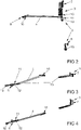
- figure 1 shows a window with a sash 2 that can be pivoted against a frame 1, with a fitting 3 for limiting the opening width of the sash 2.
- the fitting 3 has a limiting element 4 and an actuator 6 that can be controlled by a lock cylinder 5.
- FIG figure 1 a bearing part 7 of the fitting 3 is shown.
- FIG. 2 shows fitting 3 figure 1 in a fully rotationally open position.
- the fitting 3 has a fitting arrangement 8 on the frame and a fitting arrangement 9 on the sash, which are connected to one another via the delimiting element 4 .
- the frame-side fitting arrangement 8 has a bearing 10, which is fixed to the frame 1, for the delimiting element 4.
- the sash-side fitting part 9 has the bearing part 7 and a latching device 11 which has the actuator 6 that can be controlled by the lock cylinder 5.
- the sash-side fitting part 9 has a Limiting element 4 rotatably connected slider 12, which is held in the illustrated fully rotationally open position via a braking and coupling device 13 near the bearing part 7.
- figure 3 shows fitting 3 figure 1 in a limited opening width.
- the slider 12 is held here by means of the latching device 11 on a fixing part 15 attached to the wing.
- the locking device 11 prevents the movement of the slider 12 in the in figure 2 shown position and thus the movement of the in figure 1 shown wing 2 in the fully open position.
- the components of the braking and coupling device 13 are largely decoupled in this limited opening width.
- figure 4 shows the fitting 3 in the closed position, in which the in figure 1 Wing 2 shown is in the frame 1. Compared to figure 3 here the slider 12 is moved further into the fixing part 15 .
- figure 5 shows the bearing part 7 with a braking and coupling part 16 of the braking and coupling device 13 on an enlarged scale figure 2 .
- the braking and coupling part 16 can be locked in the wing 2 via a locking element 17 and is thus fixed in the movement range of the slider 12 .
- the braking and coupling part 16 In the illustrated Position is the braking and coupling part 16 fixed close to the bearing part 7 and thus allows a very large opening of the wing 2 in the fully open position.
- latching device 11 can limit the opening in the fully open position narrower.
- figure 6 shows the bearing 10 of one end of the delimiting element 4 on the frame.
- the bearing 10 has a plate 18 which can be screwed to the frame 1 and on which the limiting element 4 is rotatably mounted.
- figure 7 shows the latching device 11 with the slider 12 and adjoining areas of the delimiting element 4 in FIG figure 3 shown position in which the opening width of the fitting 3 is limited.
- one of the braking and coupling parts 14 is figure 5 described braking and coupling device 13 is arranged.
- This braking and coupling part 14 is complementary to that in figure 5 brake and coupling part 16 shown designed so that the two brake and coupling parts 14, 16 in figure 2 engage shown position of the fitting 3 and frictionally hold the wing 2 in the fully open position.
- the braking and coupling parts 14, 16 cause a braking effect on the movement of the mesh.
- One of the braking and coupling parts 14, 16, preferably the braking and coupling part 16, is designed to be elastic.
- the slider 12 is held on the fixing part 15 and has a sliding shoe 19.
- the fixing part 15 is firmly screwed to the wing 2 and has a holding arm 20 with an elongated locking recess 21.
- the actuator 6 is connected to an actuating element 22.
- figure 8 shows the latching device 11 figure 7 in an opposite and rotated view of the actuating element 22.
- FIG 9 shows a sectional view through the latching device 11 figure 8 along line IX - IX.
- the locking device 11 has a in the elongated locking recess 21 biased locking hook 23.
- a stop 24 for the locking hook 23 is arranged.
- the latching hook 23 is preloaded into the latching recess 21 by a spring element 25 .
- the actuating element 22 that can be driven by the actuator 6 penetrates into the latching recess 21 and thus into the range of movement of the latching hook 23 .
- the latching hook 23 In this position of the actuating element 22, when the wing 2 is opened, the latching hook 23 is moved over the stop 24 and the wing 2 can be moved into the fully open position. If, however, the actuating element 22 is moved into a position outside the locking recess 21, which in figure 9 is shown in phantom, the latching hook 23 remains in the position pretensioned in the latching recess 21 and, when the wing 2 is opened, reaches the limit of its opening width against the stop 24.
- the latching hook 23 has a ramp 26, so that when it moves back from the fully open position of the wing 2 is pressed into the closed position of the holding arm 20 under the stop 24 through into the recess 21.
Landscapes
- Engineering & Computer Science (AREA)
- Mechanical Engineering (AREA)
- Wing Frames And Configurations (AREA)
- Power-Operated Mechanisms For Wings (AREA)
Abstract
Description
- Die Erfindung betrifft einen Beschlag zur Begrenzung einer Öffnungsweite eines gegen einen Rahmen schwenkbaren Flügels eines Fensters, einer Fenstertür oder dergleichen mit einer flügelseitigen Beschlaganordnung und einer rahmenseitigen Beschlaganordnung, mit einem die Beschlaganordnungen miteinander verbindenden Begrenzungselement, wobei eine der Beschlaganordnungen einen Anschlag und ein dem Anschlag gegenüberstehendes Rastmittel zur Begrenzung der Öffnungsweite hat, wobei in einer der Beschlaganordnungen ein mit dem Begrenzungselement gekoppelter Gleiter längsverschieblich geführt ist und die den Gleiter führende Beschlaganordnung den Anschlag zur Begrenzung des Bewegungsbereichs aufweist.
- Ein Beschlag zur Begrenzung der Öffnungsweite eines Flügels eines Fensters ist aus der Praxis in verschiedenen Ausführungsformen bekannt. Durch die Begrenzung der Öffnungsweite wird eine Belüftung durch das Fenster ermöglicht, jedoch eine weitere Öffnung, beispielsweise aus Sicherungsgründen, verhindert. Jedoch ist es beispielsweise für Reinigungszwecke häufig erforderlich, den Flügel vollständig zu öffnen.
- Eine Öffnungsbegrenzungseinrichtung der eingangs genannten Art ist beispielsweise aus der
EP 3 034 728 A1 bekannt. Bei dieser Öffnungsbegrenzungseinrichtung lässt sich ein verschieblicher Stellkörper mit einem federnden Rastbolzen verbinden. Der Gleiter lässt sich auf den von dem Rastbolzen gehaltenen Stellkörper zu und von diesem weg bewegen. Hierdurch hat die Öffnungsbegrenzungseinrichtung sehr viele zu montierende Bauteile und ist aufwändig aufgebaut. - Eine Öffnungsbegrenzung für einen Beschlag ist aus der
EP 2 107 194 A1 bekannt. Bei dieser Öffnungsbegrenzung ist ein Anschlag zur Begrenzung der Öffnungsweite mit Rastmitteln gekoppelt, die eine Bewegung des Flügels in Schließrichtung ermöglichen und in Öffnungsrichtung verhindern. Durch Betätigung eines Entriegelungsmittels lässt sich der Anschlag entriegeln, um den Flügel über den Anschlag hinaus in Öffnungsrichtung zu bewegen. Die Bewegung des Flügels im Betrieb führt jedoch zu einer regelmäßigen Belastung der Rastmittel. Hierdurch haben die Bauteile zur Begrenzung der Öffnungsweite nur eine sehr geringe Stabilität. - Der Erfindung liegt das Problem zugrunde, einen Beschlag der eingangs genannten Art so weiter zu bilden, dass er eine hohe Stabilität aufweist und kompakt aufgebaut ist.
- Dieses Problem wird erfindungsgemäß dadurch gelöst, dass der Anschlag am Ende einer Rastausnehmung angeordnet ist und dass das Rastmittel als beweglicher Rasthaken ausgebildet ist und in die Rastausnehmung eindringt.
- Durch diese Gestaltung stellt der Gleiter eine zuverlässige Führung der Bauteile gegenüber dem Anschlag sicher. Der Gleiter kann bei heutigen, eine Falznut aufweisenden Rahmen und Flügeln einfach in der Falznut geführt werden. Hierdurch hat der Beschlag eine besonders hohe Stabilität. Zudem ist der Beschlag besonders kompakt aufgebaut. Dank der Erfindung begrenzt der Rasthaken in der einen Raststellung den Bewegungsbereich des Gleiters. Bewegt man den Rasthaken in der anderen Raststellung aus der Rastausnehmung heraus, ist der Bewegungsbereich des Gleiters von dem Anschlag gelöst.
- Eine wahlweise Freigabe oder Begrenzung der Öffnungsweite gestaltet sich gemäß einer anderen vorteilhaften Weiterbildung der Erfindung konstruktiv besonders einfach, wenn die den Gleiter aufweisende Beschlaganordnung eine Rasteinrichtung hat und wenn der Gleiter in der einen Raststellung der Rasteinrichtung mit dem Anschlag gekoppelt ist und in einer anderen Raststellung von dem Anschlag gelöst ist.
- Der Rasthaken könnte beispielsweise unmittelbar mit einem Aktor verbunden sein, um die beiden Stellungen der Rasteinrichtung anzusteuern. Die Belastung des Aktors im Betrieb des Beschlags lässt sich jedoch gemäß einer anderen vorteilhaften Weiterbildung der Erfindung besonders gering halten, wenn der Rasthaken in die Rastausnehmung vorgespannt ist und wenn ein ansteuerbarer Aktor zur Bewegung des Rasthakens aus der Rastausnehmung ausgebildet ist. Durch diese Gestaltung wird eine Belastung des Aktors vermieden, wenn das Begrenzungselement im Betrieb des Beschlags die Öffnungsweite begrenzt.
- Die Ansteuerung der Rasteinrichtung gestaltet sich gemäß einer anderen vorteilhaften Weiterbildung der Erfindung besonders einfach, wenn der Aktor ein in den Bewegungsbereich des Rasthakens bewegbares Stellelement hat und wenn in der einen Stellung des Stellelementes der Rasthaken aus dem Bewegungsbereich des Anschlages herausgedrückt ist und in der anderen Stellung dem Anschlag gegenübersteht.
- Das Stellelement lässt sich auf vielfältige Weise zwischen den beiden Stellungen antreiben. Hierzu kann beispielsweise ein einfach zu betätigender Knopf oder ein elektronisches Stellelement eingesetzt werden. Da im Betrieb die Begrenzung der Öffnungsweite beispielsweise von Reinigungspersonal oder Monteuren aufgehoben werden soll, gestaltet sich die Ansteuerung des Stellelementes gemäß einer anderen vorteilhaften Weiterbildung der Erfindung besonders einfach, wenn der Aktor einen mit dem Stellelement verbundenen Schließzylinder hat.
- Die Öffnungsweite lässt sich gemäß einer anderen vorteilhaften Weiterbildung bei der Montage des Beschlags einfach festlegen, wenn die Rastausnehmung auf einem zur feststehenden Anordnung vorgesehenen Fixierteil angeordnet ist. Durch diese Gestaltung legt die Position des Fixierteils an dem Fenster die Position des Anschlags und damit die Öffnungsweite fest. Das Fixierteil kann, wie bei Fensterbeschlägen üblich, mit dem Flügel oder dem Rahmen verschraubt oder verklemmt werden.
- Der Beschlag lässt sich gemäß einer anderen vorteilhaften Weiterbildung der Erfindung besonders einfach auf die vorgesehene Öffnungsweite anpassen, wenn das Fixierteil einen Haltearm mit der Rastausnehmung hat und wenn die Rastausnehmung eine auf die Öffnungsweite begrenzte Länge hat. Durch diese Gestaltung lässt sich einfach ein Haltearm mit einer langen Rastausnehmung einsetzen, wenn eine große Öffnungsweite gewünscht ist. Anderenfalls lässt sich ein Haltearm mit einer kurzen Rastausnehmung einsetzen, um die Öffnungsweite gering zu halten.
- Der Gleiter und das Fixierteil weisen gemäß einer anderen vorteilhaften Weiterbildung der Erfindung eine hohe Stabilität auf, wenn der Rasthaken durch eine Ausnehmung in dem Gleiter in die Rastausnehmung des Haltearms eindringt.
- Die Begrenzung der Öffnungsweite gestaltet sich gemäß einer anderen vorteilhaften Weiterbildung der Erfindung besonders einfach, wenn das Begrenzungselement an einem Ende des Gleiters gelagert ist und wenn das Fixierteil dem anderen Ende des Gleiters gegenübersteht.
- Der Beschlag lässt sich gemäß einer anderen vorteilhaften Weiterbildung der Erfindung einfach auf verschiedene Rahmen oder Flügel anpassen, wenn der Gleiter einen einer Führungsnut im Flügel oder Rahmen in der Form angepassten Gleitschuh hat und wenn der Gleitschuh mit dem Gleiter lösbar verbunden ist. Durch diese Gestaltung lassen sich für die verschiedenen Rahmen und Flügel entsprechend gestaltete Gleiter anpassen und vorrätig halten. Bei der Montage lässt sich einfach der dem Rahmen oder dem Flügel angepasste Gleitschuh mit dem Gleiter verbinden. Weiterhin kann der Gleitschuh aus einem Material mit einer hohen Gleitfähigkeit gefertigt werden, während die übrigen Bauteile des Gleiters für eine hohe Stabilität bemessen sind. Vorzugsweise ist der Gleitschuh mit dem Gleiter verrastet.
- Der Flügel lässt sich gemäß einer anderen vorteilhaften Weiterbildung der Erfindung in der vollständig geöffneten Stellung verrasten, wenn der Gleiter und ein die Beschlagteile miteinander verbindbares Lagerteil über eine Brems- und Koppeleinrichtung verrastbar miteinander verbunden sind.
- Die vollständig geöffnete Stellung lässt sich gemäß einer anderen vorteilhaften Weiterbildung der Erfindung einfach festlegen, wenn die Brems- und Koppeleinrichtung ein erstes, am Gleiter angeordnetes Koppel- und/oder Bremsteil und ein zweites, im Bewegungsbereich des Gleiters feststellbares Koppel- und/oder Bremsteil hat.
- Die Erfindung lässt zahlreiche Ausführungsformen zu. Zur weiteren Verdeutlichung ihres Grundprinzips ist eine davon in der Zeichnung dargestellt und wird nachfolgend beschrieben. Diese zeigt in
- Fig.1
- ein Fenster mit einem Beschlag zur Begrenzung der Öffnungsweite,
- Fig.2
- den Beschlag aus
Figur 1 in vollständig drehgeöffneter Stellung, - Fig.3
- den Beschlag aus
Figur 1 mit einer begrenzten Öffnungsweite, - Fig.4
- den Beschlag aus
Figur 1 in geschlossener Stellung, - Fig.5
- vergrößert ein Lagerteil des Beschlags aus
Figur 1 , - Fig.6
- eine Lagerung eines Begrenzungselementes des Beschlags aus
Figur 1 , - Fig.7
- eine Rasteinrichtung mit einem Teilbereich des Begrenzungselementes aus
Figur 6 , - Fig.8
- die Rasteinrichtung aus
Figur 7 in einer gegenüberliegenden Stellung, - Fig.9
- eine Schnittdarstellung durch die Rasteinrichtung aus
Figur 8 entlang der Linie IX - IX. -
Figur 1 zeigt ein Fenster mit einem gegen einen Rahmen 1 schwenkbaren Flügel 2 mit einem Beschlag 3 zur Begrenzung der Öffnungsweite des Flügels 2. Der Beschlag 3 hat ein Begrenzungselement 4 und einen von einem Schließzylinder 5 ansteuerbaren Aktor 6. Weiterhin ist inFigur 1 ein Lagerteil 7 des Beschlags 3 dargestellt. -
Figur 2 zeigt den Beschlag 3 ausFigur 1 in einer vollständig drehgeöffneten Stellung. Zur Vereinfachung der Darstellung sind der Rahmen 1 und der Flügel 2 nicht dargestellt. Der Beschlag 3 hat eine rahmenseitige Beschlaganordnung 8 und eine flügelseitige Beschlaganordnung 9, welche über das Begrenzungselement 4 miteinander verbunden sind. Die rahmenseitige Beschlaganordnung 8 hat eine fest mit dem Rahmen 1 verbundene Lagerung 10 für das Begrenzungselement 4. Das flügelseitige Beschlagteil 9 hat das Lagerteil 7 und eine den von dem Schließzylinder 5 ansteuerbaren Aktor 6 aufweisende Rasteinrichtung 11. Weiterhin hat das flügelseitige Beschlagteil 9 einen mit dem Begrenzungselement 4 drehbeweglich verbundenen Gleiter 12, welcher in der dargestellten vollständig drehgeöffneten Stellung über eine Brems- und Koppeleinrichtung 13 nahe des Lagerteils 7 gehalten ist. -
Figur 3 zeigt den Beschlag 3 ausFigur 1 in einer begrenzten Öffnungsweite. Der Gleiter 12 ist hier mittels der Rasteinrichtung 11 an einem am Flügel befestigten Fixierteil 15 gehalten. Die Rasteinrichtung 11 verhindert die Bewegung des Gleiters 12 in die inFigur 2 dargestellte Stellung und damit die Bewegung des inFigur 1 dargestellten Flügels 2 in die vollständig drehgeöffnete Stellung. Die Bauteile der Brems- und Koppeleinrichtung 13 sind in dieser begrenzten Öffnungsweite weit entkoppelt. -
Figur 4 zeigt den Beschlag 3 in geschlossener Stellung, in der der inFigur 1 dargestellte Flügel 2 im Rahmen 1 liegt. Im Vergleich zuFigur 3 ist hier der Gleiter 12 weiter in das Fixierteil 15 hinein bewegt. -
Figur 5 zeigt vergrößert das Lagerteil 7 mit einem Brems- und Koppelteil 16 der Brems- und Koppeleinrichtung 13 ausFigur 2 . Das Brems- und Koppelteil 16 lässt sich über ein Feststellelement 17 in dem Flügel 2 verrasten und ist damit im Bewegungsbereich des Gleiters 12 fixiert. In der dargestellten Stellung ist das Brems- und Koppelteil 16 nahe am Lagerteil 7 fixiert und ermöglicht damit eine sehr große Öffnung des Flügels 2 in der vollständig geöffneten Stellung. Durch Montage des Brems- und Koppelteils 16 näher an der in denFiguren 2 bis 4 dargestellten Rasteinrichtung 11 lässt sich die Öffnung in der vollständig geöffneten Stellung enger begrenzen. Zur Vereinfachung der Darstellung sind in denFiguren 5 bis 7 der Rahmen 1 und der Flügel 2 strichpunktiert dargestellt. -
Figur 6 zeigt die Lagerung 10 des einen Endes des Begrenzungselementes 4 am Rahmen. Die Lagerung 10 hat eine mit dem Rahmen 1 verschraubbare Platte 18, auf der das Begrenzungselement 4 drehbeweglich gelagert ist. -
Figur 7 zeigt die Rasteinrichtung 11 mit dem Gleiter 12 und angrenzenden Bereichen des Begrenzungselementes 4 in der inFigur 3 dargestellten Stellung, in der die Öffnungsweite des Beschlags 3 begrenzt ist. An der Lagerung des Gleiters 12 am Begrenzungselement 4 ist eines der Brems- und Koppelteile 14 der inFigur 5 beschriebenen Brems- und Koppeleinrichtung 13 angeordnet. Dieses Brems- und Koppelteil14 ist komplementär zu dem inFigur 5 dargestellten Brems- und Koppelteil 16 gestaltet, so dass die beiden Brems- und Koppelteile 14, 16 in der inFigur 2 dargestellten Stellung des Beschlags 3 ineinander greifen und den Flügel 2 in der vollständig geöffneten Stellung kraftschlüssig haltern. Zudem bewirken die Brems- und Koppelteile 14, 16 eine Bremswirkung bei der Bewegung des Ineinandergreifens. Dabei ist eines der Brems- und Koppelteile 14, 16, bevorzugt das Brems- und Koppelteil 16, elastisch ausgeführt. Der Gleiter 12 ist an dem Fixierteil 15 gehalten und hat einen Gleitschuh 19. Das Fixierteil 15 ist mit dem Flügel 2 fest verschraubt und hat einen Haltearm 20 mit einer lang gestreckten Rastausnehmung 21. Der Aktor 6 ist mit einem Stellelement 22 verbunden. -
Figur 8 zeigt die Rasteinrichtung 11 ausFigur 7 in einer gegenüberliegenden und gedrehten Ansicht auf das Stellelement 22. -
Figur 9 zeigt eine Schnittdarstellung durch die Rasteinrichtung 11 ausFigur 8 entlang der Linie IX - IX. Zur Vereinfachung ist in denFiguren 8 und 9 der Gleitschuh 19 von dem Gleiter 12 entfernt. Die Rasteinrichtung 11 hat einen in die lang gestreckte Rastausnehmung 21 vorgespannten Rasthaken 23. Am Ende der Rastausnehmung 21 ist ein Anschlag 24 für den Rasthaken 23 angeordnet. Der Rasthaken 23 ist von einem Federelement 25 in die Rastausnehmung 21 vorgespannt. Das von dem Aktor 6 antreibbare Stellelement 22 dringt in die Rastausnehmung 21 und damit in den Bewegungsbereich des Rasthakens 23 ein. In dieser Stellung des Stellelementes 22 wird bei einer Öffnung des Flügels 2 der Rasthaken 23 über den Anschlag 24 hinweg bewegt und der Flügel 2 kann in die vollständig geöffnete Stellung bewegt werden. Verstellt man das Stellelement 22 jedoch in eine außerhalb der Rastausnehmung 21 befindliche Stellung, welche inFigur 9 strichpunktiert dargestellt ist, verbleibt der Rasthaken 23 in der in die Rastausnehmung 21 vorgespannten Stellung und gelangt bei der Öffnung des Flügels 2 zur Begrenzung dessen Öffnungsweite gegen den Anschlag 24. Der Rasthaken 23 hat eine Rampe 26, so dass er bei der Rückbewegung aus der vollständig geöffneten Stellung des Flügels 2 in die geschlossene Stellung von dem Haltearm 20 unter den Anschlag 24 hindurch in die Rastausnehmung 21 gedrückt wird.
Claims (12)
- Beschlag (3) zur Begrenzung einer Öffnungsweite eines gegen einen Rahmen (1) schwenkbaren Flügels (2) eines Fensters, einer Fenstertür oder dergleichen mit einer flügelseitigen Beschlaganordnung (9) und einer rahmenseitigen Beschlaganordnung (8), mit einem die Beschlaganordnungen (8, 9) miteinander verbindenden Begrenzungselement (4), wobei eine der Beschlaganordnungen (8, 9) einen Anschlag (24) und ein dem Anschlag (24) gegenüberstehendes Rastmittel zur Begrenzung der Öffnungsweite hat, wobei in einer der Beschlaganordnungen (8, 9) ein mit dem Begrenzungselement (4) gekoppelter Gleiter (12) längsverschieblich geführt ist und die den Gleiter (12) führende Beschlaganordnung (9) den Anschlag (24) aufweist dadurch gekennzeichnet, dass der Anschlag (24) am Ende einer Rastausnehmung (21) angeordnet ist und dass das Rastmittel als beweglicher Rasthaken (23) ausgebildet ist und in die Rastausnehmung (21) eindringt.
- Beschlag nach Anspruch 1, dadurch gekennzeichnet, dass die den Gleiter aufweisende Beschlaganordnung (9) eine Rasteinrichtung (11) hat und dass der Gleiter (12) in der einen Raststellung der Rasteinrichtung (11) mit dem Anschlag (24) gekoppelt ist und in einer anderen Raststellung von dem Anschlag (24) gelöst ist.
- Beschlag nach Anspruch 1 oder 2, dadurch gekennzeichnet, dass der Rasthaken (23) in die Rastausnehmung (21) vorgespannt ist und dass ein ansteuerbarer Aktor (6) zur Bewegung des Rasthakens (23) aus der Rastausnehmung (21) ausgebildet ist.
- Beschlag nach Anspruch 3, dadurch gekennzeichnet, dass der Aktor (6) ein in den Bewegungsbereich des Rasthakens (23) bewegbares Stellelement (22) hat und dass in der einen Stellung des Stellelementes (22) der Rasthaken (23) aus dem Bewegungsbereich des Anschlages (24) herausgedrückt ist und in der anderen Stellung dem Anschlag (24) gegenübersteht.
- Beschlag nach Anspruch 4, dadurch gekennzeichnet, dass der Aktor (6) einen mit dem Stellelement (22) verbundenen Schließzylinder (5) hat.
- Beschlag nach zumindest einem der Ansprüche 1 bis 5, dadurch gekennzeichnet, dass die Rastausnehmung (21) auf einem zur feststehenden Anordnung vorgesehenen Fixierteil (15) angeordnet ist.
- Beschlag nach Anspruch 6, dadurch gekennzeichnet, dass das Fixierteil (15) einen Haltearm (20) mit der Rastausnehmung (21) hat und dass die Rastausnehmung (21) eine auf die Öffnungsweite begrenzte Länge hat.
- Beschlag nach zumindest einem der Ansprüche 1 bis 7, dadurch gekennzeichnet, dass der Rasthaken (23) durch eine Ausnehmung in dem Gleiter (12) in die Rastausnehmung (21) des Haltearms (20) eindringt.
- Beschlag nach zumindest einem der Ansprüche 1 bis 8, dadurch gekennzeichnet, dass das Begrenzungselement (4) an einem Ende des Gleiters (12) gelagert ist und dass das Fixierteil (15) dem anderen Ende des Gleiters (12) gegenübersteht.
- Beschlag nach zumindest einem der Ansprüche 1 bis 9, dadurch gekennzeichnet, dass der Gleiter (12) einen einer Führungsnut im Flügel (2) oder Rahmen (1) in der Form angepassten Gleitschuh (19) hat und dass der Gleitschuh mit dem Gleiter lösbar verbunden ist.
- Beschlag nach zumindest einem der Ansprüche 1 bis 10, dadurch gekennzeichnet, dass der Gleiter (12) und ein die Beschlagteile (8, 9) miteinander verbindbares Lagerteil (7) über eine Brems- und Koppeleinrichtung (13) verrastbar miteinander verbunden sind.
- Beschlag nach Anspruch 11, dadurch gekennzeichnet, dass die Brems- und Koppeleinrichtung (13) ein erstes, am Gleiter (12) angeordnetes Koppel- und/oder Bremsteil (14) und ein zweites, im Bewegungsbereich des Gleiters (12) feststellbares Koppel- und/oder Bremsteil (16) hat.
Applications Claiming Priority (1)
| Application Number | Priority Date | Filing Date | Title |
|---|---|---|---|
| DE102021200538.1A DE102021200538A1 (de) | 2021-01-21 | 2021-01-21 | Beschlag zur Begrenzung einer Öffnungsweite eines gegen einen Rahmen schwenkbaren Flügels eines Fensters |
Publications (2)
| Publication Number | Publication Date |
|---|---|
| EP4033058A1 true EP4033058A1 (de) | 2022-07-27 |
| EP4033058B1 EP4033058B1 (de) | 2024-07-31 |
Family
ID=79316906
Family Applications (1)
| Application Number | Title | Priority Date | Filing Date |
|---|---|---|---|
| EP22150852.6A Active EP4033058B1 (de) | 2021-01-21 | 2022-01-11 | Beschlag zur begrenzung einer öffnungsweite eines gegen einen rahmen schwenkbaren flügels eines fensters |
Country Status (3)
| Country | Link |
|---|---|
| EP (1) | EP4033058B1 (de) |
| DE (1) | DE102021200538A1 (de) |
| PL (1) | PL4033058T3 (de) |
Citations (7)
| Publication number | Priority date | Publication date | Assignee | Title |
|---|---|---|---|---|
| GB2149450A (en) * | 1983-11-10 | 1985-06-12 | Bezault Sa | Open/Closing attachment for a frame and cooperating window door or panel which is openable and closable |
| GB2246393A (en) * | 1990-07-27 | 1992-01-29 | Securistyle Ltd | A window restricting device |
| GB2260161A (en) * | 1991-09-27 | 1993-04-07 | Securistyle Ltd | A stay restricting device |
| GB2273526A (en) * | 1992-12-17 | 1994-06-22 | Euromond Ltd | Stays |
| EP2085552A1 (de) * | 2008-01-31 | 2009-08-05 | J. Banks & Co. Ltd. | Dreistangen-Scharnier mit Fensterbegrenzer |
| EP2107194A1 (de) | 2008-04-04 | 2009-10-07 | Schüco International KG | Öffnungsbegrenzung für ein Fenster oder eine Tür |
| EP3034728A1 (de) | 2014-12-18 | 2016-06-22 | Wilh. Schlechtendahl & Söhne GmbH & Co. KG | Öffnungsbegrenzereinrichtung |
-
2021
- 2021-01-21 DE DE102021200538.1A patent/DE102021200538A1/de active Pending
-
2022
- 2022-01-11 PL PL22150852.6T patent/PL4033058T3/pl unknown
- 2022-01-11 EP EP22150852.6A patent/EP4033058B1/de active Active
Patent Citations (7)
| Publication number | Priority date | Publication date | Assignee | Title |
|---|---|---|---|---|
| GB2149450A (en) * | 1983-11-10 | 1985-06-12 | Bezault Sa | Open/Closing attachment for a frame and cooperating window door or panel which is openable and closable |
| GB2246393A (en) * | 1990-07-27 | 1992-01-29 | Securistyle Ltd | A window restricting device |
| GB2260161A (en) * | 1991-09-27 | 1993-04-07 | Securistyle Ltd | A stay restricting device |
| GB2273526A (en) * | 1992-12-17 | 1994-06-22 | Euromond Ltd | Stays |
| EP2085552A1 (de) * | 2008-01-31 | 2009-08-05 | J. Banks & Co. Ltd. | Dreistangen-Scharnier mit Fensterbegrenzer |
| EP2107194A1 (de) | 2008-04-04 | 2009-10-07 | Schüco International KG | Öffnungsbegrenzung für ein Fenster oder eine Tür |
| EP3034728A1 (de) | 2014-12-18 | 2016-06-22 | Wilh. Schlechtendahl & Söhne GmbH & Co. KG | Öffnungsbegrenzereinrichtung |
Also Published As
| Publication number | Publication date |
|---|---|
| PL4033058T3 (pl) | 2024-09-30 |
| EP4033058B1 (de) | 2024-07-31 |
| DE102021200538A1 (de) | 2022-07-21 |
Similar Documents
| Publication | Publication Date | Title |
|---|---|---|
| EP2354402B1 (de) | Verriegelung für Flügelanlagen | |
| DE102016202377A1 (de) | Beschlaganordnung zur Anbindung eines schieb- und kippbaren Flügels | |
| EP3835526A1 (de) | Schiebe- und drehflügelsystem | |
| DE102006010755A1 (de) | Verstellvorrichtung für einen Schiebedachdeckel an einem Fahrzeug | |
| EP4033058A1 (de) | Beschlag zur begrenzung einer öffnungsweite eines gegen einen rahmen schwenkbaren flügels eines fensters | |
| DE202017105264U1 (de) | Zusatzverriegelung für eine Türanordnung | |
| EP2343429A2 (de) | Abstützeinrichtung für einen gegen einen Rahmen schwenkbaren Flügel | |
| EP3708743A1 (de) | Stulphebelgetriebe zur wahlweisen verriegelung oder entriegelung eines unterschlagenen flügels von zweiflügeligen fenstern | |
| EP3371397B1 (de) | Beschlaganordnung | |
| DE10013697A1 (de) | Feststellvorrichtung | |
| EP2772604A2 (de) | Öffnungsbegrenzer | |
| DE102021115490A1 (de) | Feststellvorrichtung für beidseitig angeschlagene Tür | |
| DE102006007672A1 (de) | Dichtungsanordnung eines Fensters, einer Tür oder dgl. | |
| EP4056797A1 (de) | Treibstangenbeschlag für einen gegen einen rahmen schwenkbaren flügel | |
| EP1498563B1 (de) | Spaltlüftungsvorrichtung | |
| EP4628689A1 (de) | Öffnungsbegrenzungseinrichtung für einen treibstangenbeschlag | |
| EP0457014A2 (de) | Türverriegelung und mit dieser ausgestatteter Schrankwagen | |
| DE102021124629B4 (de) | Verschlussvorrichtung, insbesondere für einen Wohnwagen oder Wohnmobil | |
| DE202004004769U1 (de) | Beschlaganordnung | |
| EP3868984B1 (de) | Hebelgetriebe für einen in einer falzluft verdeckt angeordneten treibstangenbeschlag | |
| EP4215704B1 (de) | Sperrvorrichtung, beschlag und flügel-rahmenanordnung | |
| EP2196609B1 (de) | Beschlagteil für einen Treibstangenbeschlag | |
| EP2090730B1 (de) | Verriegelungsvorrichtung | |
| DE102023210536A1 (de) | Einrichtung zur Kopplung eines Schiebebeschlagbauteils | |
| DE102012213782A1 (de) | Verlagerungsanordnung zur Verlagerung eines Schiebeflügels eines Fensters, einer Tür oder dergleichen relativ zu einer festen Einfassung mit einem flügelseitigen und einem einfassungsseitigen Steuerelement |
Legal Events
| Date | Code | Title | Description |
|---|---|---|---|
| PUAI | Public reference made under article 153(3) epc to a published international application that has entered the european phase |
Free format text: ORIGINAL CODE: 0009012 |
|
| STAA | Information on the status of an ep patent application or granted ep patent |
Free format text: STATUS: THE APPLICATION HAS BEEN PUBLISHED |
|
| AK | Designated contracting states |
Kind code of ref document: A1 Designated state(s): AL AT BE BG CH CY CZ DE DK EE ES FI FR GB GR HR HU IE IS IT LI LT LU LV MC MK MT NL NO PL PT RO RS SE SI SK SM TR |
|
| STAA | Information on the status of an ep patent application or granted ep patent |
Free format text: STATUS: REQUEST FOR EXAMINATION WAS MADE |
|
| 17P | Request for examination filed |
Effective date: 20221215 |
|
| RBV | Designated contracting states (corrected) |
Designated state(s): AL AT BE BG CH CY CZ DE DK EE ES FI FR GB GR HR HU IE IS IT LI LT LU LV MC MK MT NL NO PL PT RO RS SE SI SK SM TR |
|
| P01 | Opt-out of the competence of the unified patent court (upc) registered |
Effective date: 20230516 |
|
| STAA | Information on the status of an ep patent application or granted ep patent |
Free format text: STATUS: EXAMINATION IS IN PROGRESS |
|
| 17Q | First examination report despatched |
Effective date: 20231031 |
|
| GRAP | Despatch of communication of intention to grant a patent |
Free format text: ORIGINAL CODE: EPIDOSNIGR1 |
|
| STAA | Information on the status of an ep patent application or granted ep patent |
Free format text: STATUS: GRANT OF PATENT IS INTENDED |
|
| INTG | Intention to grant announced |
Effective date: 20240321 |
|
| GRAS | Grant fee paid |
Free format text: ORIGINAL CODE: EPIDOSNIGR3 |
|
| GRAA | (expected) grant |
Free format text: ORIGINAL CODE: 0009210 |
|
| STAA | Information on the status of an ep patent application or granted ep patent |
Free format text: STATUS: THE PATENT HAS BEEN GRANTED |
|
| AK | Designated contracting states |
Kind code of ref document: B1 Designated state(s): AL AT BE BG CH CY CZ DE DK EE ES FI FR GB GR HR HU IE IS IT LI LT LU LV MC MK MT NL NO PL PT RO RS SE SI SK SM TR |
|
| REG | Reference to a national code |
Ref country code: CH Ref legal event code: EP Ref country code: GB Ref legal event code: FG4D Free format text: NOT ENGLISH |
|
| REG | Reference to a national code |
Ref country code: DE Ref legal event code: R096 Ref document number: 502022001324 Country of ref document: DE |
|
| REG | Reference to a national code |
Ref country code: IE Ref legal event code: FG4D Free format text: LANGUAGE OF EP DOCUMENT: GERMAN |
|
| REG | Reference to a national code |
Ref country code: DE Ref legal event code: R081 Ref document number: 502022001324 Country of ref document: DE Owner name: AUG. WINKHAUS SE & CO. KG, DE Free format text: FORMER OWNER: AUG. WINKHAUS GMBH & CO. KG, 48291 TELGTE, DE Ref country code: DE Ref legal event code: R081 Ref document number: 502022001324 Country of ref document: DE Owner name: AUG. WINKHAUS SE, DE Free format text: FORMER OWNER: AUG. WINKHAUS GMBH & CO. KG, 48291 TELGTE, DE |
|
| REG | Reference to a national code |
Ref country code: LT Ref legal event code: MG9D |
|
| RAP4 | Party data changed (patent owner data changed or rights of a patent transferred) |
Owner name: AUG. WINKHAUS SE & CO. KG |
|
| REG | Reference to a national code |
Ref country code: NL Ref legal event code: MP Effective date: 20240731 |
|
| PG25 | Lapsed in a contracting state [announced via postgrant information from national office to epo] |
Ref country code: PT Free format text: LAPSE BECAUSE OF FAILURE TO SUBMIT A TRANSLATION OF THE DESCRIPTION OR TO PAY THE FEE WITHIN THE PRESCRIBED TIME-LIMIT Effective date: 20241202 |
|
| PG25 | Lapsed in a contracting state [announced via postgrant information from national office to epo] |
Ref country code: PT Free format text: LAPSE BECAUSE OF FAILURE TO SUBMIT A TRANSLATION OF THE DESCRIPTION OR TO PAY THE FEE WITHIN THE PRESCRIBED TIME-LIMIT Effective date: 20241202 |
|
| PG25 | Lapsed in a contracting state [announced via postgrant information from national office to epo] |
Ref country code: NO Free format text: LAPSE BECAUSE OF FAILURE TO SUBMIT A TRANSLATION OF THE DESCRIPTION OR TO PAY THE FEE WITHIN THE PRESCRIBED TIME-LIMIT Effective date: 20241031 |
|
| PG25 | Lapsed in a contracting state [announced via postgrant information from national office to epo] |
Ref country code: NL Free format text: LAPSE BECAUSE OF FAILURE TO SUBMIT A TRANSLATION OF THE DESCRIPTION OR TO PAY THE FEE WITHIN THE PRESCRIBED TIME-LIMIT Effective date: 20240731 Ref country code: FI Free format text: LAPSE BECAUSE OF FAILURE TO SUBMIT A TRANSLATION OF THE DESCRIPTION OR TO PAY THE FEE WITHIN THE PRESCRIBED TIME-LIMIT Effective date: 20240731 Ref country code: GR Free format text: LAPSE BECAUSE OF FAILURE TO SUBMIT A TRANSLATION OF THE DESCRIPTION OR TO PAY THE FEE WITHIN THE PRESCRIBED TIME-LIMIT Effective date: 20241101 |
|
| PG25 | Lapsed in a contracting state [announced via postgrant information from national office to epo] |
Ref country code: BG Free format text: LAPSE BECAUSE OF FAILURE TO SUBMIT A TRANSLATION OF THE DESCRIPTION OR TO PAY THE FEE WITHIN THE PRESCRIBED TIME-LIMIT Effective date: 20240731 |
|
| PG25 | Lapsed in a contracting state [announced via postgrant information from national office to epo] |
Ref country code: LV Free format text: LAPSE BECAUSE OF FAILURE TO SUBMIT A TRANSLATION OF THE DESCRIPTION OR TO PAY THE FEE WITHIN THE PRESCRIBED TIME-LIMIT Effective date: 20240731 |
|
| PG25 | Lapsed in a contracting state [announced via postgrant information from national office to epo] |
Ref country code: IS Free format text: LAPSE BECAUSE OF FAILURE TO SUBMIT A TRANSLATION OF THE DESCRIPTION OR TO PAY THE FEE WITHIN THE PRESCRIBED TIME-LIMIT Effective date: 20241130 |
|
| PG25 | Lapsed in a contracting state [announced via postgrant information from national office to epo] |
Ref country code: HR Free format text: LAPSE BECAUSE OF FAILURE TO SUBMIT A TRANSLATION OF THE DESCRIPTION OR TO PAY THE FEE WITHIN THE PRESCRIBED TIME-LIMIT Effective date: 20240731 |
|
| PG25 | Lapsed in a contracting state [announced via postgrant information from national office to epo] |
Ref country code: RS Free format text: LAPSE BECAUSE OF FAILURE TO SUBMIT A TRANSLATION OF THE DESCRIPTION OR TO PAY THE FEE WITHIN THE PRESCRIBED TIME-LIMIT Effective date: 20241031 Ref country code: ES Free format text: LAPSE BECAUSE OF FAILURE TO SUBMIT A TRANSLATION OF THE DESCRIPTION OR TO PAY THE FEE WITHIN THE PRESCRIBED TIME-LIMIT Effective date: 20240731 |
|
| PG25 | Lapsed in a contracting state [announced via postgrant information from national office to epo] |
Ref country code: RS Free format text: LAPSE BECAUSE OF FAILURE TO SUBMIT A TRANSLATION OF THE DESCRIPTION OR TO PAY THE FEE WITHIN THE PRESCRIBED TIME-LIMIT Effective date: 20241031 Ref country code: NO Free format text: LAPSE BECAUSE OF FAILURE TO SUBMIT A TRANSLATION OF THE DESCRIPTION OR TO PAY THE FEE WITHIN THE PRESCRIBED TIME-LIMIT Effective date: 20241031 Ref country code: NL Free format text: LAPSE BECAUSE OF FAILURE TO SUBMIT A TRANSLATION OF THE DESCRIPTION OR TO PAY THE FEE WITHIN THE PRESCRIBED TIME-LIMIT Effective date: 20240731 Ref country code: LV Free format text: LAPSE BECAUSE OF FAILURE TO SUBMIT A TRANSLATION OF THE DESCRIPTION OR TO PAY THE FEE WITHIN THE PRESCRIBED TIME-LIMIT Effective date: 20240731 Ref country code: IS Free format text: LAPSE BECAUSE OF FAILURE TO SUBMIT A TRANSLATION OF THE DESCRIPTION OR TO PAY THE FEE WITHIN THE PRESCRIBED TIME-LIMIT Effective date: 20241130 Ref country code: HR Free format text: LAPSE BECAUSE OF FAILURE TO SUBMIT A TRANSLATION OF THE DESCRIPTION OR TO PAY THE FEE WITHIN THE PRESCRIBED TIME-LIMIT Effective date: 20240731 Ref country code: GR Free format text: LAPSE BECAUSE OF FAILURE TO SUBMIT A TRANSLATION OF THE DESCRIPTION OR TO PAY THE FEE WITHIN THE PRESCRIBED TIME-LIMIT Effective date: 20241101 Ref country code: FI Free format text: LAPSE BECAUSE OF FAILURE TO SUBMIT A TRANSLATION OF THE DESCRIPTION OR TO PAY THE FEE WITHIN THE PRESCRIBED TIME-LIMIT Effective date: 20240731 Ref country code: ES Free format text: LAPSE BECAUSE OF FAILURE TO SUBMIT A TRANSLATION OF THE DESCRIPTION OR TO PAY THE FEE WITHIN THE PRESCRIBED TIME-LIMIT Effective date: 20240731 Ref country code: BG Free format text: LAPSE BECAUSE OF FAILURE TO SUBMIT A TRANSLATION OF THE DESCRIPTION OR TO PAY THE FEE WITHIN THE PRESCRIBED TIME-LIMIT Effective date: 20240731 |
|
| PG25 | Lapsed in a contracting state [announced via postgrant information from national office to epo] |
Ref country code: SM Free format text: LAPSE BECAUSE OF FAILURE TO SUBMIT A TRANSLATION OF THE DESCRIPTION OR TO PAY THE FEE WITHIN THE PRESCRIBED TIME-LIMIT Effective date: 20240731 Ref country code: RO Free format text: LAPSE BECAUSE OF FAILURE TO SUBMIT A TRANSLATION OF THE DESCRIPTION OR TO PAY THE FEE WITHIN THE PRESCRIBED TIME-LIMIT Effective date: 20240731 Ref country code: DK Free format text: LAPSE BECAUSE OF FAILURE TO SUBMIT A TRANSLATION OF THE DESCRIPTION OR TO PAY THE FEE WITHIN THE PRESCRIBED TIME-LIMIT Effective date: 20240731 |
|
| PG25 | Lapsed in a contracting state [announced via postgrant information from national office to epo] |
Ref country code: EE Free format text: LAPSE BECAUSE OF FAILURE TO SUBMIT A TRANSLATION OF THE DESCRIPTION OR TO PAY THE FEE WITHIN THE PRESCRIBED TIME-LIMIT Effective date: 20240731 |
|
| PG25 | Lapsed in a contracting state [announced via postgrant information from national office to epo] |
Ref country code: CZ Free format text: LAPSE BECAUSE OF FAILURE TO SUBMIT A TRANSLATION OF THE DESCRIPTION OR TO PAY THE FEE WITHIN THE PRESCRIBED TIME-LIMIT Effective date: 20240731 |
|
| PG25 | Lapsed in a contracting state [announced via postgrant information from national office to epo] |
Ref country code: SK Free format text: LAPSE BECAUSE OF FAILURE TO SUBMIT A TRANSLATION OF THE DESCRIPTION OR TO PAY THE FEE WITHIN THE PRESCRIBED TIME-LIMIT Effective date: 20240731 Ref country code: IT Free format text: LAPSE BECAUSE OF FAILURE TO SUBMIT A TRANSLATION OF THE DESCRIPTION OR TO PAY THE FEE WITHIN THE PRESCRIBED TIME-LIMIT Effective date: 20240731 |
|
| REG | Reference to a national code |
Ref country code: DE Ref legal event code: R097 Ref document number: 502022001324 Country of ref document: DE |
|
| PLBE | No opposition filed within time limit |
Free format text: ORIGINAL CODE: 0009261 |
|
| STAA | Information on the status of an ep patent application or granted ep patent |
Free format text: STATUS: NO OPPOSITION FILED WITHIN TIME LIMIT |
|
| 26N | No opposition filed |
Effective date: 20250501 |
|
| REG | Reference to a national code |
Ref country code: CH Ref legal event code: PL |
|
| REG | Reference to a national code |
Ref country code: DE Ref legal event code: R081 Ref document number: 502022001324 Country of ref document: DE Owner name: AUG. WINKHAUS SE, DE Free format text: FORMER OWNER: AUG. WINKHAUS SE & CO. KG, 48291 TELGTE, DE |
|
| PG25 | Lapsed in a contracting state [announced via postgrant information from national office to epo] |
Ref country code: SE Free format text: LAPSE BECAUSE OF FAILURE TO SUBMIT A TRANSLATION OF THE DESCRIPTION OR TO PAY THE FEE WITHIN THE PRESCRIBED TIME-LIMIT Effective date: 20240731 |
|
| PG25 | Lapsed in a contracting state [announced via postgrant information from national office to epo] |
Ref country code: MC Free format text: LAPSE BECAUSE OF FAILURE TO SUBMIT A TRANSLATION OF THE DESCRIPTION OR TO PAY THE FEE WITHIN THE PRESCRIBED TIME-LIMIT Effective date: 20240731 Ref country code: LU Free format text: LAPSE BECAUSE OF NON-PAYMENT OF DUE FEES Effective date: 20250111 |
|
| PG25 | Lapsed in a contracting state [announced via postgrant information from national office to epo] |
Ref country code: FR Free format text: LAPSE BECAUSE OF NON-PAYMENT OF DUE FEES Effective date: 20250131 |
|
| PG25 | Lapsed in a contracting state [announced via postgrant information from national office to epo] |
Ref country code: CH Free format text: LAPSE BECAUSE OF NON-PAYMENT OF DUE FEES Effective date: 20250131 |
|
| PG25 | Lapsed in a contracting state [announced via postgrant information from national office to epo] |
Ref country code: IE Free format text: LAPSE BECAUSE OF NON-PAYMENT OF DUE FEES Effective date: 20250111 |
|
| PGFP | Annual fee paid to national office [announced via postgrant information from national office to epo] |
Ref country code: GB Payment date: 20260122 Year of fee payment: 5 |
|
| PGFP | Annual fee paid to national office [announced via postgrant information from national office to epo] |
Ref country code: DE Payment date: 20260120 Year of fee payment: 5 |
|
| PGFP | Annual fee paid to national office [announced via postgrant information from national office to epo] |
Ref country code: AT Payment date: 20260301 Year of fee payment: 5 |
|
| PGFP | Annual fee paid to national office [announced via postgrant information from national office to epo] |
Ref country code: BE Payment date: 20260121 Year of fee payment: 5 |
|
| PGFP | Annual fee paid to national office [announced via postgrant information from national office to epo] |
Ref country code: PL Payment date: 20260109 Year of fee payment: 5 |