EP4032837A1 - Powder supply apparatus - Google Patents
Powder supply apparatus Download PDFInfo
- Publication number
- EP4032837A1 EP4032837A1 EP20864614.1A EP20864614A EP4032837A1 EP 4032837 A1 EP4032837 A1 EP 4032837A1 EP 20864614 A EP20864614 A EP 20864614A EP 4032837 A1 EP4032837 A1 EP 4032837A1
- Authority
- EP
- European Patent Office
- Prior art keywords
- powder
- recess
- measuring shaft
- supply apparatus
- cylinder
- Prior art date
- Legal status (The legal status is an assumption and is not a legal conclusion. Google has not performed a legal analysis and makes no representation as to the accuracy of the status listed.)
- Pending
Links
Images


Classifications
-
- B—PERFORMING OPERATIONS; TRANSPORTING
- B65—CONVEYING; PACKING; STORING; HANDLING THIN OR FILAMENTARY MATERIAL
- B65G—TRANSPORT OR STORAGE DEVICES, e.g. CONVEYORS FOR LOADING OR TIPPING, SHOP CONVEYOR SYSTEMS OR PNEUMATIC TUBE CONVEYORS
- B65G65/00—Loading or unloading
- B65G65/30—Methods or devices for filling or emptying bunkers, hoppers, tanks, or like containers, of interest apart from their use in particular chemical or physical processes or their application in particular machines, e.g. not covered by a single other subclass
- B65G65/34—Emptying devices
- B65G65/40—Devices for emptying otherwise than from the top
- B65G65/44—Devices for emptying otherwise than from the top using reciprocating conveyors, e.g. jigging conveyors
-
- B—PERFORMING OPERATIONS; TRANSPORTING
- B22—CASTING; POWDER METALLURGY
- B22F—WORKING METALLIC POWDER; MANUFACTURE OF ARTICLES FROM METALLIC POWDER; MAKING METALLIC POWDER; APPARATUS OR DEVICES SPECIALLY ADAPTED FOR METALLIC POWDER
- B22F12/00—Apparatus or devices specially adapted for additive manufacturing; Auxiliary means for additive manufacturing; Combinations of additive manufacturing apparatus or devices with other processing apparatus or devices
- B22F12/50—Means for feeding of material, e.g. heads
-
- G—PHYSICS
- G01—MEASURING; TESTING
- G01F—MEASURING VOLUME, VOLUME FLOW, MASS FLOW OR LIQUID LEVEL; METERING BY VOLUME
- G01F11/00—Apparatus requiring external operation adapted at each repeated and identical operation to measure and separate a predetermined volume of fluid or fluent solid material from a supply or container, without regard to weight, and to deliver it
- G01F11/10—Apparatus requiring external operation adapted at each repeated and identical operation to measure and separate a predetermined volume of fluid or fluent solid material from a supply or container, without regard to weight, and to deliver it with measuring chambers moved during operation
- G01F11/26—Apparatus requiring external operation adapted at each repeated and identical operation to measure and separate a predetermined volume of fluid or fluent solid material from a supply or container, without regard to weight, and to deliver it with measuring chambers moved during operation wherein the measuring chamber is filled and emptied by tilting or inverting the supply vessel, e.g. bottle-emptying apparatus
- G01F11/261—Apparatus requiring external operation adapted at each repeated and identical operation to measure and separate a predetermined volume of fluid or fluent solid material from a supply or container, without regard to weight, and to deliver it with measuring chambers moved during operation wherein the measuring chamber is filled and emptied by tilting or inverting the supply vessel, e.g. bottle-emptying apparatus for fluent solid material
-
- B—PERFORMING OPERATIONS; TRANSPORTING
- B22—CASTING; POWDER METALLURGY
- B22F—WORKING METALLIC POWDER; MANUFACTURE OF ARTICLES FROM METALLIC POWDER; MAKING METALLIC POWDER; APPARATUS OR DEVICES SPECIALLY ADAPTED FOR METALLIC POWDER
- B22F12/00—Apparatus or devices specially adapted for additive manufacturing; Auxiliary means for additive manufacturing; Combinations of additive manufacturing apparatus or devices with other processing apparatus or devices
- B22F12/50—Means for feeding of material, e.g. heads
- B22F12/57—Metering means
-
- B—PERFORMING OPERATIONS; TRANSPORTING
- B29—WORKING OF PLASTICS; WORKING OF SUBSTANCES IN A PLASTIC STATE IN GENERAL
- B29C—SHAPING OR JOINING OF PLASTICS; SHAPING OF MATERIAL IN A PLASTIC STATE, NOT OTHERWISE PROVIDED FOR; AFTER-TREATMENT OF THE SHAPED PRODUCTS, e.g. REPAIRING
- B29C64/00—Additive manufacturing, i.e. manufacturing of three-dimensional [3D] objects by additive deposition, additive agglomeration or additive layering, e.g. by 3D printing, stereolithography or selective laser sintering
- B29C64/30—Auxiliary operations or equipment
- B29C64/307—Handling of material to be used in additive manufacturing
- B29C64/321—Feeding
-
- B—PERFORMING OPERATIONS; TRANSPORTING
- B29—WORKING OF PLASTICS; WORKING OF SUBSTANCES IN A PLASTIC STATE IN GENERAL
- B29C—SHAPING OR JOINING OF PLASTICS; SHAPING OF MATERIAL IN A PLASTIC STATE, NOT OTHERWISE PROVIDED FOR; AFTER-TREATMENT OF THE SHAPED PRODUCTS, e.g. REPAIRING
- B29C64/00—Additive manufacturing, i.e. manufacturing of three-dimensional [3D] objects by additive deposition, additive agglomeration or additive layering, e.g. by 3D printing, stereolithography or selective laser sintering
- B29C64/30—Auxiliary operations or equipment
- B29C64/307—Handling of material to be used in additive manufacturing
- B29C64/343—Metering
-
- B—PERFORMING OPERATIONS; TRANSPORTING
- B33—ADDITIVE MANUFACTURING TECHNOLOGY
- B33Y—ADDITIVE MANUFACTURING, i.e. MANUFACTURING OF THREE-DIMENSIONAL [3-D] OBJECTS BY ADDITIVE DEPOSITION, ADDITIVE AGGLOMERATION OR ADDITIVE LAYERING, e.g. BY 3-D PRINTING, STEREOLITHOGRAPHY OR SELECTIVE LASER SINTERING
- B33Y30/00—Apparatus for additive manufacturing; Details thereof or accessories therefor
-
- B—PERFORMING OPERATIONS; TRANSPORTING
- B65—CONVEYING; PACKING; STORING; HANDLING THIN OR FILAMENTARY MATERIAL
- B65G—TRANSPORT OR STORAGE DEVICES, e.g. CONVEYORS FOR LOADING OR TIPPING, SHOP CONVEYOR SYSTEMS OR PNEUMATIC TUBE CONVEYORS
- B65G65/00—Loading or unloading
- B65G65/30—Methods or devices for filling or emptying bunkers, hoppers, tanks, or like containers, of interest apart from their use in particular chemical or physical processes or their application in particular machines, e.g. not covered by a single other subclass
- B65G65/34—Emptying devices
- B65G65/40—Devices for emptying otherwise than from the top
- B65G65/48—Devices for emptying otherwise than from the top using other rotating means, e.g. rotating pressure sluices in pneumatic systems
- B65G65/4881—Devices for emptying otherwise than from the top using other rotating means, e.g. rotating pressure sluices in pneumatic systems rotating about a substantially horizontal axis
-
- G—PHYSICS
- G01—MEASURING; TESTING
- G01F—MEASURING VOLUME, VOLUME FLOW, MASS FLOW OR LIQUID LEVEL; METERING BY VOLUME
- G01F11/00—Apparatus requiring external operation adapted at each repeated and identical operation to measure and separate a predetermined volume of fluid or fluent solid material from a supply or container, without regard to weight, and to deliver it
- G01F11/10—Apparatus requiring external operation adapted at each repeated and identical operation to measure and separate a predetermined volume of fluid or fluent solid material from a supply or container, without regard to weight, and to deliver it with measuring chambers moved during operation
- G01F11/12—Apparatus requiring external operation adapted at each repeated and identical operation to measure and separate a predetermined volume of fluid or fluent solid material from a supply or container, without regard to weight, and to deliver it with measuring chambers moved during operation of the valve type, i.e. the separating being effected by fluid-tight or powder-tight movements
- G01F11/20—Apparatus requiring external operation adapted at each repeated and identical operation to measure and separate a predetermined volume of fluid or fluent solid material from a supply or container, without regard to weight, and to deliver it with measuring chambers moved during operation of the valve type, i.e. the separating being effected by fluid-tight or powder-tight movements wherein the measuring chamber rotates or oscillates
- G01F11/24—Apparatus requiring external operation adapted at each repeated and identical operation to measure and separate a predetermined volume of fluid or fluent solid material from a supply or container, without regard to weight, and to deliver it with measuring chambers moved during operation of the valve type, i.e. the separating being effected by fluid-tight or powder-tight movements wherein the measuring chamber rotates or oscillates for fluent solid material
-
- B—PERFORMING OPERATIONS; TRANSPORTING
- B65—CONVEYING; PACKING; STORING; HANDLING THIN OR FILAMENTARY MATERIAL
- B65G—TRANSPORT OR STORAGE DEVICES, e.g. CONVEYORS FOR LOADING OR TIPPING, SHOP CONVEYOR SYSTEMS OR PNEUMATIC TUBE CONVEYORS
- B65G2201/00—Indexing codes relating to handling devices, e.g. conveyors, characterised by the type of product or load being conveyed or handled
- B65G2201/04—Bulk
- B65G2201/042—Granular material
-
- G—PHYSICS
- G01—MEASURING; TESTING
- G01F—MEASURING VOLUME, VOLUME FLOW, MASS FLOW OR LIQUID LEVEL; METERING BY VOLUME
- G01F23/00—Indicating or measuring liquid level or level of fluent solid material, e.g. indicating in terms of volume or indicating by means of an alarm
Abstract
Description
- The present invention relates to a powder supply apparatus.
- Solid materials obtained by applying a high pressure to evenly spread powder have been recently used for industrial application. Such solid materials typically need, for example, highly accurate shapes. Thus, a constant amount of powder is necessary for forming the solid materials. Hence, apparatuses for supplying powder (powder supply apparatuses) as uniformly as possible are used for apparatuses for forming the solid materials.
-
Japanese Patent Laid-Open No. 2016-147253 Patent Literature 1 discharges air from the measuring recess, thereby securely dropping powder from the measuring recess. - In the powder supply apparatus described in
Patent Literature 1, powder in the measuring recess of the rod-like member is dropped and supplied therefrom by rotating the rod-like member about the axis 180° at an original position of the rod-like member. Hence, if powder with low flowability is used in the powder supply apparatus described inPatent Literature 1, the powder may be supplied from the measuring recess before the measuring recess is filled with a fixed amount of the powder. Moreover, powder having small particle diameters may adhere to a portion other than the measuring recess of the rod-like member by, for example, the powder entering between the rod-like member and a sliding contact portion, and the powder adhering to the rod-like member may be supplied together with the powder in the measuring recess. If a trace amount of powder less than 1.0 gf [9.8 × 10⁻³ N] is supplied, a small increase or decrease in the weight of the powder to be supplied may account for a large proportion of the powder to be supplied. This may lead to difficulty in supplying a fixed amount of powder. - Furthermore, in the powder supply apparatus described in
Patent Literature 1, various configurations such as apowder agitation mechanism 50 and a hopper unit 21 for filling a measuring recess 34 with powder are required above a predetermined position for supplying powder, as illustrated inFIG. 1 ofPatent Literature 1. A space above the predetermined position for supplying powder is necessary for a downstream process (e.g., a process for spreading powder) of the powder supply apparatus. The absence of such a space may limit apparatuses to be used in the downstream process. - Hence, an object of present invention is to provide a powder supply apparatus that can supply even a fixed trace amount of powder and secure a space above a predetermined position for supplying powder.
- In order to solve the problem, a powder supply apparatus according to a first invention includes:
- a measuring shaft having a recess to be filled with powder;
- a powder filling mechanism for filling the recess of the measuring shaft with the powder;
- a slide mechanism for sliding the measuring shaft along an axis of the measuring shaft;
- a leveling member for leveling off the powder in the recess by a slide of the measuring shaft; and
- an axial rotation mechanism that directs the recess downward by rotating the measuring shaft about the axis of the measuring shaft and supplies the leveled powder in the recess downward from the recess by dropping the powder.
- A powder supply apparatus according to a second invention, wherein the powder filling mechanism in the powder supply apparatus according to the first invention includes:
- a cylinder in which at least the recess of the measuring shaft is allowed to be placed and the powder is disposed; and
- a cylinder rotation mechanism that rotates the cylinder so as to agitate the powder in the cylinder and fill the recess with the powder.
- A powder supply apparatus according to a third invention, wherein the powder filling mechanism in the powder supply apparatus according to the second invention further includes a powder agitator blade projecting from the inner surface of the cylinder.
- Furthermore, a powder supply apparatus according to a fourth invention, wherein the powder filling mechanism in the powder supply apparatus according to one of the second and third inventions further includes an air blowing unit that agitates the powder by blowing air in the cylinder.
- A powder supply apparatus according to a fifth invention, wherein the leveling member in the powder supply apparatus according to one of the second and third inventions is a member having a shaft through hole for guiding the recess of the measuring shaft from the inside to the outside of the cylinder by the slide of the measuring shaft.
- A powder supply apparatus according to a sixth invention, in the powder supply apparatus according to any one of the first to third inventions, further includes a shaft vibration mechanism for facilitating the drop of the powder from the recess facing downward by vibrations.
- A powder supply apparatus according to a seventh invention includes, in the powder supply apparatus according to any one of the first to third inventions, a detector for detecting a filling state of the powder in the recess after the powder is leveled off by the leveling member; and
a control mechanism that causes the slide mechanism to slide the measuring shaft to a position for filling the recess with the powder and causes the powder filling mechanism to fill the recess with the powder if the detector detects an insufficient filling state of the powder. - The powder supply apparatus supplies powder leveled off by the leveling member, so that even a fixed trace amount of the powder can be supplied. Moreover, the powder is supplied from the recess after being slid from a position for filling the recess with the powder, thereby securing a space above the predetermined position for supplying the powder.
-
- [
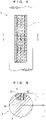
FIG. 1] FIG. 1 is a schematic side view illustrating a powder supply apparatus according to an embodiment of the present invention, in which a recess of a measuring shaft is filled with powder. - [
FIG. 2] FIG. 2 is a schematic side view illustrating the powder supply apparatus, in which the powder in the recess is leveled off. - [
FIG. 3] FIG. 3 is a schematic side view illustrating the powder supply apparatus, in which the leveled powder in the recess is supplied downward due to a drop of the powder. - [
FIG. 4] FIG. 4 is a plan view of the measuring shaft. - [
FIG. 5] FIG. 5 is a cross-sectional view taken along line A-A ofFIG. 4 . - [
FIG. 6] FIG. 6 is a partially cut perspective view illustrating the powder supply apparatus, in which the powder in the recess is leveled off. - [
FIG. 7] FIG. 7 is a cross-sectional view illustrating a cylinder constituting a powder filling mechanism for the powder supply apparatus. - [
FIG. 8] FIG. 8 is a cross-sectional view illustrating a modification of the cylinder. - [
FIG. 9] FIG. 9 is a partially cut perspective view illustrating the powder supply apparatus, in which the powder in the recess is leveled off. - [
FIG. 10] FIG. 10 is a partially cut perspective view illustrating the powder supply apparatus, in which the leveled powder in the recess is supplied downward due to a drop of the powder. - [
FIG. 11] FIG. 11 illustrates a cross section of the measuring shaft and another configuration. - [
FIG. 12] FIG. 12 is a schematic side view illustrating the powder supply apparatus including a detector and a controller, in which leveled powder is detected. - [
FIG. 13] FIG. 13 is a schematic side view illustrating the powder supply apparatus with the reoriented detector, in which powder is detected immediately before being supplied. - A powder supply apparatus according to an embodiment of the present invention will be described below in accordance with the accompanying drawings.
- First, referring to
FIGS. 1 to 3 , the powder supply apparatus will be schematically described below.FIGS. 1 to 3 are schematic side views of the powder supply apparatus. - As illustrated in
FIG. 1 , apowder supply apparatus 1 includes ameasuring shaft 2 having arecess 3 to be filled with powder P, and apowder filling mechanism 5 for filling therecess 3 of themeasuring shaft 2 with the powder P. As illustrated inFIG. 2 , thepowder supply apparatus 1 includes aslide mechanism 6 for sliding themeasuring shaft 2 along anaxis 4 of themeasuring shaft 2, and aleveling member 7 for leveling off the powder P in therecess 3 by a slide of themeasuring shaft 2. Furthermore, as illustrated inFIG. 3 , thepowder supply apparatus 1 includes anaxial rotation mechanism 8 that directs therecess 3 downward by rotating themeasuring shaft 2 about theaxis 4 and supplies the leveled powder P in therecess 3 downward from therecess 3 to apredetermined position 10 by dropping the powder P. - First, in a method of using the
powder supply apparatus 1, thepowder filling mechanism 5 fills therecess 3 of themeasuring shaft 2 with the powder P as illustrated inFIG. 1 . The powder P in therecess 3 may protrude from therecess 3. Subsequently, as illustrated inFIG. 2 , theslide mechanism 6 slides themeasuring shaft 2, causing theleveling member 7 to level off the powder P in therecess 3. The leveling causes a protruding portion of the powder P from therecess 3 to drop from therecess 3. Thereafter, as illustrated inFIG. 3 , theaxial rotation mechanism 8 rotates themeasuring shaft 2 about theaxis 4 so as to direct therecess 3 downward. The powder P drops downward from therecess 3 facing downward, so that the powder P is supplied to thepredetermined position 10 below therecess 3. - Referring to
FIGS. 4 to 11 , the configurations of thepowder supply apparatus 1 will be specifically described below.FIG. 4 is a plan view of the measuringshaft 2,FIG. 5 is a cross-sectional view taken along line A-A ofFIG. 4 , andFIG. 6 is a partially cut perspective view of thepowder supply apparatus 1.FIGS. 7 and 8 are cross-sectional views of thepowder filling mechanism 5,FIGS. 9 and10 are partially cut perspective views of thepowder supply apparatus 1, andFIG. 11 illustrates a cross section of the measuringshaft 2 and another configuration. - As illustrated in
FIG. 4 , therecess 3 of the measuringshaft 2 is, for example, rectangular in plan view. The rectangular shape is preferably extended with a ratio of about 1:20 to 1:40 between the short side and the long side. This is because theextended recess 3 in plan view causes the powder P supplied from therecess 3 to extend like therecess 3 in plan view, so that the supplied powder P is suitably shaped to be spread by a squeegee or the like in a downstream process. In other words, this is because the powder P can be evenly supplied along the width direction of a squeegee or the like. Therecess 3 is not always rectangular in plan view and may have any other shapes like an ellipse or an oval. - As illustrated in
FIG. 5 , therecess 3 of the measuringshaft 2 is an opening withsides 32 and a bottom 33. An angle θ formed between theside 32 and the bottom 33 of therecess 3 is preferably an obtuse angle. If the angle θ is an obtuse angle, the powder P easily falls from therecess 3 facing downward. If the powder P easily falls from therecess 3 facing downward, the powder P is hardly left in therecess 3 facing downward, so that even a fixed trace amount of the powder P can be supplied. The bottom 33 of therecess 3 is preferably shallower than theaxis 4 of the measuring shaft 2 (h < r). This is because the bottom 33 at a lesser depth causes the powder P in therecess 3 to receive a centrifugal force applied from the measuringshaft 2 rotated by theaxial rotation mechanism 8 and the powder P easily falls from therecess 3 facing downward. - As illustrated in
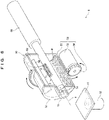
FIG. 6 , thepowder filling mechanism 5 includes, for example, acylinder 50 in which therecess 3 of the measuringshaft 2 can be placed. The powder P is placed in thecylinder 50. InFIG. 6 (also inFIGS. 9 and10 described later), the illustratedcylinder 50 is cut in half lengthwise to indicate the inside of thecylinder 50. Furthermore, thepowder filling mechanism 5 includes, for example, acylinder rotation mechanism 54 for rotating thecylinder 50. Thecylinder rotation mechanism 54 rotates thecylinder 50 so as to agitate the powder P, and then the agitated powder P fills therecess 3. Thecylinder rotation mechanism 54 includes, for example, adriving gear 56 connected to the output shaft of amotor 55 and a drivengear 57 that is engaged with thedriving gear 56 and is attached to the outer surface of thecylinder 50. - As illustrated in
FIGS. 6 and7 , thepowder filling mechanism 5 further includes, for example,powder agitator blades 58 projecting from the inner surface of thecylinder 50. Thepowder agitator blades 58 accelerate the agitation of the powder P in thecylinder 50 in response to a rotation of thecylinder 50. The acceleration of the agitation of the powder P smashes clumps of the powder P, so that even a fixed trace amount of the powder P can be supplied. As illustrated inFIG. 7 , the multiple (two in the example ofFIG. 7 )powder agitator blades 58 are preferably provided to further accelerate agitation. The blades are more preferably disposed at regular intervals. In this configuration, at least one of thepowder agitator blades 58 preferably has a length such that a tip of the one of thepowder agitator blades 58 is separated from the measuringshaft 2 by only a small distance (d) (that is, the long powder agitator blade 58). This configuration allows the longpowder agitator blade 58 to rotate to level off the powder P that fills therecess 3 and protrudes from the outer surface of the measuringshaft 2, so that therecess 3 is stably filled with the powder P. The distance (d) between the longpowder agitator blade 58 and the measuringshaft 2 is preferably equal to or smaller than a depth (h) of therecess 3. Thecylinder 50 may be circular or polygonal (square in the example ofFIG. 8 ) in cross section. As illustrated inFIG. 8 , thecylinder 50 shaped like a polygon, e.g., a square in cross section easily transports the powder P upward from a corner of thecylinder 50 in response to a rotation of thecylinder 50, thereby accelerating the agitation of the powder P. Thepowder filling mechanism 5 includes, for example, anair blowing unit 59 that agitates the powder P by blowing air a in thecylinder 50. Thecylinder 50, in which theair blowing unit 59 blows the air a, may have any shapes in addition to a square in cross section inFIG. 8 . - As illustrated in
FIGS. 9 and10 , thepowder supply apparatus 1 includes arotary cylinder 68 that slides the measuringshaft 2 along theaxis 4 and rotates the measuringshaft 2 about theaxis 4. In other words, therotary cylinder 68 acts as theslide mechanism 6 and theaxial rotation mechanism 8. - As illustrated in
FIGS. 9 and10 , thecylinder 50 includes abody 51, a proximal-end cover plate 52 that is disposed on one end of thebody 51 and through which the proximal end of the measuringshaft 2 penetrates, a distal-end cover plate 72 that is disposed on the other end of thebody 51 and through which the distal end of the measuringshaft 2 is allowed to penetrate, and aboss member 73 that is provided on the outer surface of the distal-end cover plate 72 and through which the distal end of the measuringshaft 2 is allowed to penetrate. A shaft throughhole 74 formed in the distal-end cover plate 72 and theboss member 73 is a space for guiding therecess 3 of the measuringshaft 2 from the inside to the outside of thecylinder 50 by a slide of the measuringshaft 2. In other words, the distal-end cover plate 72 and theboss member 73 that have the shaft throughhole 74 correspond to the levelingmember 7. If the distal-end cover plate 72 and theboss member 73 are not integrated but are provided as different members, the powder P in therecess 3 is actually leveled off by the distal-end cover plate 72 facing the inside of thecylinder 50. Thus, the distal-end cover plate 72 corresponds to the levelingmember 7. The cross section of the shaft throughhole 74 is preferably as large as or slightly larger than the cross section of the measuring shaft 2 (for example, by a tolerance). The shaft throughhole 74 configured thus reduces variations in the amount of the powder P that is leveled off and left in therecess 3. By reducing variations in the amount of the powder P that is leveled off and left in therecess 3, even a fixed trace amount of the powder P can be supplied. - As illustrated in
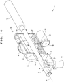
FIGS. 10 and11 , a liftingplate 11 may be provided as thepredetermined position 10 where the dropped powder P is supplied from therecess 3, and alifting cylinder 12 may be provided to lift and lower thelifting plate 11. As illustrated inFIG. 11 , the liftingcylinder 12 can lift the liftingplate 11 to a proper height of the liftingplate 11 when the powder P is supplied from therecess 3. In this configuration, the height of the liftingplate 11 is preferably set such that a distance (h + α) between the lower end of the measuringshaft 2 and a surface on which the powder P is supplied from therecess 3 is larger than a depth (h) of therecess 3 by a small distance (α). This is because the height can minimize a drop height (h + α) of the powder P dropped from therecess 3, so that the supplied powder P is not deformed by the drop and is suitably shaped to be spread by a squeegee or the like in a downstream process. - As illustrated in
FIG. 11 , ashaft vibration mechanism 9 for vibrating the measuringshaft 2 may be provided. Theshaft vibration mechanism 9 facilitates the drop of the powder P from therecess 3 by vibrating the measuringshaft 2 with therecess 3 facing downward. - A method of using the
powder supply apparatus 1 will be specifically described below. - First, as illustrated in
FIGS. 6 and7 , thecylinder 50 is rotated by thecylinder rotation mechanism 54. The powder P disposed in thecylinder 50 is agitated by the rotation. The agitated powder P rises above therecess 3 of the measuringshaft 2, so that therecess 3 is filled with the powder P. - Subsequently, when the powder P filling the
recess 3 protrudes therefrom, the measuringshaft 2 is slid by therotary cylinder 68 as illustrated inFIG. 9 . A time when the powder P filling therecess 3 protrudes therefrom can be estimated from the number of revolutions or the time of revolution of thecylinder 50. When the number of revolutions or the time of revolution is reached, the measuringshaft 2 may be automatically slid by therotary cylinder 68. The slide of the measuringshaft 2 moves therecess 3 from the inside to the outside of thecylinder 50 through the shaft throughhole 74. When therecess 3 passes through the shaft throughhole 74, the powder P protruding from therecess 3 is leveled off. Thus, therecess 3 moves out of thecylinder 50 while the powder P filling therecess 3 is leveled off. - Thereafter, as illustrated in
FIGS. 10 and11 , the liftingplate 11 is lifted by the liftingcylinder 12. Specifically, as illustrated inFIG. 11 , the liftingplate 11 is lifted to the preferable height. Therotary cylinder 68 rotates the measuringshaft 2 about theaxis 4 so as to direct therecess 3 downward. When therecess 3 moves out of thecylinder 50 and the liftingplate 11 reaches the preferable position, the measuringshaft 2 may be automatically rotated about theaxis 4 by therotary cylinder 68. The powder P drops to the liftingplate 11 from therecess 3 facing downward, so that the powder P is supplied to the liftingplate 11. In order to facilitate the drop, theshaft vibration mechanism 9 vibrates the measuringshaft 2 with therecess 3 facing downward. - In this way, the
powder supply apparatus 1 supplies the powder P leveled off by the levelingmember 7, so that even a fixed trace amount of the powder P can be supplied. Moreover, the powder P is supplied from therecess 3 after being slid from a position for filling therecess 3 with the powder P, thereby securing a space above thepredetermined position 10 for supplying the powder P. - Moreover, the
cylinder 50 with the powder P disposed therein is rotated by thecylinder rotation mechanism 54, thereby agitating the powder P in thecylinder 50 so as to smash clumps of the powder P. Thus, even a fixed trace amount of the powder P can be supplied. Furthermore, thecylinder 50 with the powder P disposed therein is rotated by thecylinder rotation mechanism 54, allowing estimation of a time when therecess 3 is filled with the powder P. Thus, the configuration can be suitable for automation. - Additionally, the agitation of the powder P is accelerated by the
powder agitator blades 58 and theair blowing unit 59 in thecylinder 50 so as to further smash clumps of the powder P. Thus, even a fixed trace amount of the powder P can be supplied. - Moreover, the leveling
member 7 is a member (distal-end cover plate 72) constituting thecylinder 50, achieving a simple configuration. - The
shaft vibration mechanism 9 vibrating the measuringshaft 2 easily drops the powder P from therecess 3 facing downward, so that even a fixed trace amount of the powder P can be supplied. - The powder P is not specifically described in the present embodiment. The powder P may be any powder and is not limited. The preferable powder P supplied in the
powder supply apparatus 1 is spread by a squeegee or the like in a downstream process and then is formed into a solid material under a high pressure. - In the foregoing embodiment, only the measuring
shaft 2 circular in cross section is illustrated. The measuringshaft 2 may have other shapes such as a polygon. - A filling state is preferably confirmed before the leveled powder P is supplied downward, though the confirmation is not described in the foregoing embodiment. The confirmation may be a visual check but is preferably made by devices in view of reliability and automation. As illustrated in
FIGS. 12 and 13 , configurations necessary for the confirmation by devices are adetector 30 and acontrol mechanism 65. Thedetector 30 detects a filling state of the powder P in therecess 3 after the powder P is leveled off by the levelingmember 7. Specifically, thedetector 30 is, for example, a laser measuring machine or a camera (image detection) that measures the shape of therecess 3 or recognizes a state of filling of therecess 3 with the powder P. If thedetector 30 detects an insufficient filling state, thecontrol mechanism 65 causes theslide mechanism 6 to slide the measuringshaft 2 to a position for filling (refilling) therecess 3 with the powder P and causes thepowder filling mechanism 5 to fill (refill) therecess 3 with the powder P. The insufficient filling state means that a necessary amount of the powder P for being supplied fixedly has not filled therecess 3. Thecontrol mechanism 65 is specifically, for example, a control panel including a determination unit for determining whether a filling state detected by thedetector 30 is insufficient or not, and an instruction unit for providing instructions for thepowder filling mechanism 5 and theslide mechanism 6. Thedetector 30 inFIG. 12 is oriented to detect a filling state of the powder P leveled off by the levelingmember 7. Thus, in the case of an insufficient filling state of the leveled powder P, thecontrol mechanism 65 immediately refills therecess 3 with the powder P, thereby shortening a time for supplying a fixed amount of the powder P. Thedetector 30 inFIG. 13 is oriented to detect a filling state of the powder P immediately before the powder P is supplied downward. This can reliably supply a fixed amount of the powder P. Thepowder supply apparatus 1 may be provided with both of thedetector 30 inFIG. 12 and thedetector 30 inFIG. 13 . - Furthermore, the foregoing embodiment is merely exemplary and is not restrictive in all the aspects. The scope of the present invention is not indicated by the foregoing description but the claims. The scope of the present invention is intended to include meanings equivalent to the claims and all changes in the scope. From among the configurations described in the embodiment, the configurations other than those described as a first invention in "Solution to Problem" are optional and thus can be deleted and changed as appropriate.
Claims (7)
- A powder supply apparatus comprising:a measuring shaft having a recess to be filled with powder;a powder filling mechanism for filling the recess of the measuring shaft with the powder;a slide mechanism for sliding the measuring shaft along an axis of the measuring shaft;a leveling member for leveling off the powder in the recess by a slide of the measuring shaft; andan axial rotation mechanism that directs the recess downward by rotating the measuring shaft about the axis of the measuring shaft and supplies the leveled powder in the recess downward from the recess by dropping the powder.
- The powder supply apparatus according to claim 1, wherein the powder filling mechanism includes:a cylinder in which at least the recess of the measuring shaft is allowed to be placed and the powder is disposed; anda cylinder rotation mechanism that rotates the cylinder so as to agitate the powder in the cylinder and fill the recess with the powder.
- The powder supply apparatus according to claim 2, wherein the powder filling mechanism further includes a powder agitator blade projecting from an inner surface of the cylinder.
- The powder supply apparatus according to one of claims 2 and 3, wherein the powder filling mechanism further includes an air blowing unit that agitates the powder by blowing air in the cylinder.
- The powder supply apparatus according to one of claims 2 and 3, wherein the leveling member is a member having a shaft through hole for guiding the recess of the measuring shaft from inside to outside of the cylinder by the slide of the measuring shaft.
- The powder supply apparatus according to any one of claims 1 to 3, further comprising a shaft vibration mechanism for facilitating the drop of the powder from the recess facing downward by vibrations.
- The powder supply apparatus according to any one of claims 1 to 3, further comprising a detector for detecting a filling state of the powder in the recess after the powder is leveled off by the leveling member; and
a control mechanism that causes the slide mechanism to slide the measuring shaft to a position for filling the recess with the powder and causes the powder filling mechanism to fill the recess with the powder if the detector detects an insufficient filling state of the powder.
Applications Claiming Priority (2)
| Application Number | Priority Date | Filing Date | Title |
|---|---|---|---|
| JP2019170951 | 2019-09-20 | ||
| PCT/JP2020/034838 WO2021054310A1 (en) | 2019-09-20 | 2020-09-15 | Powder supply apparatus |
Publications (2)
| Publication Number | Publication Date |
|---|---|
| EP4032837A1 true EP4032837A1 (en) | 2022-07-27 |
| EP4032837A4 EP4032837A4 (en) | 2023-11-01 |
Family
ID=74883213
Family Applications (1)
| Application Number | Title | Priority Date | Filing Date |
|---|---|---|---|
| EP20864614.1A Pending EP4032837A4 (en) | 2019-09-20 | 2020-09-15 | Powder supply apparatus |
Country Status (5)
| Country | Link |
|---|---|
| US (1) | US20220268616A1 (en) |
| EP (1) | EP4032837A4 (en) |
| JP (1) | JP7324279B2 (en) |
| KR (1) | KR20220061949A (en) |
| WO (1) | WO2021054310A1 (en) |
Family Cites Families (28)
| Publication number | Priority date | Publication date | Assignee | Title |
|---|---|---|---|---|
| US2856807A (en) * | 1954-04-13 | 1958-10-21 | Noble D Stutzman | Powder measuring dispenser |
| US3201001A (en) * | 1962-10-12 | 1965-08-17 | Borden Co | Pulverulent materials dispenser |
| GB1118520A (en) * | 1967-06-20 | 1968-07-03 | Maharaj Krishen Mehta | Dispensing apparatus for use in encapsulating powders |
| JPS5252960A (en) * | 1975-10-27 | 1977-04-28 | Tadashi Iijima | Device for quantitatively supplying coloring material |
| JPS53150714U (en) * | 1977-05-02 | 1978-11-28 | ||
| DE2914238C2 (en) * | 1979-03-02 | 1981-04-23 | Schweizerische Aluminium AG, 3965 Chippis | Device for the continuous feeding of alumina by means of a metering device |
| DE3217406C2 (en) * | 1982-05-08 | 1986-06-05 | Pfister Gmbh, 8900 Augsburg | Device for continuous gravimetric dosing of loose material |
| JPS59206717A (en) * | 1983-05-10 | 1984-11-22 | Hiroshi Adachi | Powder measuring device |
| JPS60102623U (en) * | 1983-12-20 | 1985-07-12 | 東洋自動機株式会社 | Weighing device |
| JPS61501655A (en) * | 1984-03-29 | 1986-08-07 | エンクシュトレム、ニルス・ゲ− | Automotive power testing equipment |
| US4635829A (en) * | 1985-05-30 | 1987-01-13 | Brittingham Jr Louis W | Measured volume dispenser |
| FR2587081B1 (en) * | 1985-09-11 | 1988-04-15 | Bp Chimie Sa | ROTARY-TYPE DOSING DEVICE FOR DELIVERING GRANULAR SUBSTANCES |
| US4751948A (en) * | 1985-10-30 | 1988-06-21 | Kendall Mcgaw Laboratories, Inc. | Method and apparatus for the accurate delivery of powders |
| US4890535A (en) * | 1989-01-24 | 1990-01-02 | Bieber William J | Apparatus and method for measuring and dispensing powder |
| FR2647208B1 (en) * | 1989-05-16 | 1993-09-24 | Cloup Philippe | DEVICE FOR DOSING A LIQUID CONTAINED IN A FIRST CHAMBER AND FOR TRANSFERRING IN SMALL DOSES IN A FLUID FLOWING IN A SECOND CHAMBER |
| JP2599220Y2 (en) * | 1993-10-18 | 1999-08-30 | エフエム技研株式会社 | Powder mixing equipment |
| JP3220431B2 (en) | 1998-06-23 | 2001-10-22 | ピップフジモト株式会社 | Weighing tool |
| JP2000266643A (en) * | 1999-03-15 | 2000-09-29 | Tokyo Rika Kikai Kk | Granule sample quantitative distributor |
| US6470163B1 (en) * | 1999-10-27 | 2002-10-22 | Canon Kabushiki Kaisha | Developer stirring member, assembly method and recycling method for the same |
| KR100864713B1 (en) * | 2006-07-20 | 2008-10-23 | 삼성전자주식회사 | Toner agitating film, toner agitating member, and toner supplying apparatus having the same |
| GB0813242D0 (en) * | 2008-07-18 | 2008-08-27 | Mcp Tooling Technologies Ltd | Powder dispensing apparatus and method |
| GB201020646D0 (en) * | 2010-12-06 | 2011-01-19 | Molins Plc | Apparatus for dispensing powder |
| JP2014061913A (en) * | 2012-09-21 | 2014-04-10 | Yokoyama Corp | Measuring container for powder and granular material |
| WO2015008348A1 (en) * | 2013-07-17 | 2015-01-22 | 日本たばこ産業株式会社 | Volumetric feed apparatus for particulate materials, and volumetric feed method for same |
| KR101523437B1 (en) * | 2013-10-28 | 2015-05-27 | 김진복 | Device for feeding fixed-quantity powder material |
| US9296502B1 (en) * | 2014-08-05 | 2016-03-29 | Aaron Hollander | Ground coffee dispenser for making coffee pods |
| JP2016147253A (en) | 2015-02-13 | 2016-08-18 | 関西ペイント株式会社 | Powder supply device |
| JP2016204131A (en) * | 2015-04-24 | 2016-12-08 | トヨタ自動車株式会社 | Powder supply device |
-
2020
- 2020-09-15 US US17/630,183 patent/US20220268616A1/en active Pending
- 2020-09-15 WO PCT/JP2020/034838 patent/WO2021054310A1/en unknown
- 2020-09-15 EP EP20864614.1A patent/EP4032837A4/en active Pending
- 2020-09-15 JP JP2021520439A patent/JP7324279B2/en active Active
- 2020-09-15 KR KR1020227003897A patent/KR20220061949A/en unknown
Also Published As
| Publication number | Publication date |
|---|---|
| JP7324279B2 (en) | 2023-08-09 |
| KR20220061949A (en) | 2022-05-13 |
| EP4032837A4 (en) | 2023-11-01 |
| US20220268616A1 (en) | 2022-08-25 |
| JPWO2021054310A1 (en) | 2021-03-25 |
| WO2021054310A1 (en) | 2021-03-25 |
Similar Documents
| Publication | Publication Date | Title |
|---|---|---|
| JP5792652B2 (en) | Stirring device, discharge device including the same, and discharge method | |
| EP4032837A1 (en) | Powder supply apparatus | |
| US4392591A (en) | Apparatus for metering semi-flowable material | |
| JP2005289379A (en) | Powder filling apparatus and its operating method | |
| JP2011173626A (en) | Apparatus for filling minute amount of powder body | |
| US6000446A (en) | Apparatus for particulate processing | |
| US10336081B2 (en) | Method of maintaining a fluidic dispensing device | |
| CN110813157B (en) | Powder supply device for powder dispenser | |
| KR20110058794A (en) | Material filling device and material filling method | |
| JP5195037B2 (en) | Powder filling equipment | |
| EP3616894B1 (en) | Compression molding system and method of controlling the same | |
| JP5643079B2 (en) | Plunger insertion device, adapter for plunger insertion device, and method for manufacturing syringe unit | |
| CN115178136B (en) | Flexible processing equipment for precise electronic component | |
| EP3157660B1 (en) | Mixer for viscous fluids and method of mixing viscous fluids | |
| JP4858961B2 (en) | Powder filling equipment | |
| JP2015227855A (en) | Agitation device, agitation method and automatic analysis device having agitation device | |
| KR100698788B1 (en) | Constant weighing feeder apparatus for powder material | |
| US9931851B1 (en) | Fluidic dispensing device and stir bar feedback method and use thereof | |
| JP6718725B2 (en) | Three-dimensional rotation/revolution type stirring device | |
| JP3430148B2 (en) | Ground improvement construction method and construction management device | |
| CN219885156U (en) | Vibration type bridge-proof fertilizer metering bin | |
| JP2006130492A (en) | Stirring and de-aerating methods of stirred material filling lengthwise container of syringe or the like, and its device | |
| EP4067864A1 (en) | Viscous liquid supply device | |
| CN219129100U (en) | Gravity center adjustable counterweight | |
| CN105727784B (en) | The mixing device of 3D printer |
Legal Events
| Date | Code | Title | Description |
|---|---|---|---|
| STAA | Information on the status of an ep patent application or granted ep patent |
Free format text: STATUS: THE INTERNATIONAL PUBLICATION HAS BEEN MADE |
|
| PUAI | Public reference made under article 153(3) epc to a published international application that has entered the european phase |
Free format text: ORIGINAL CODE: 0009012 |
|
| STAA | Information on the status of an ep patent application or granted ep patent |
Free format text: STATUS: REQUEST FOR EXAMINATION WAS MADE |
|
| 17P | Request for examination filed |
Effective date: 20220315 |
|
| AK | Designated contracting states |
Kind code of ref document: A1 Designated state(s): AL AT BE BG CH CY CZ DE DK EE ES FI FR GB GR HR HU IE IS IT LI LT LU LV MC MK MT NL NO PL PT RO RS SE SI SK SM TR |
|
| DAV | Request for validation of the european patent (deleted) | ||
| DAX | Request for extension of the european patent (deleted) | ||
| A4 | Supplementary search report drawn up and despatched |
Effective date: 20231005 |
|
| RIC1 | Information provided on ipc code assigned before grant |
Ipc: B33Y 30/00 20150101ALI20230928BHEP Ipc: B29C 64/343 20170101ALI20230928BHEP Ipc: B29C 64/321 20170101ALI20230928BHEP Ipc: B22F 12/57 20210101ALI20230928BHEP Ipc: B22F 12/50 20210101ALI20230928BHEP Ipc: G01F 11/24 20060101ALI20230928BHEP Ipc: B65G 65/48 20060101ALI20230928BHEP Ipc: B65G 65/44 20060101AFI20230928BHEP |