EP4032782A1 - Train control system - Google Patents
Train control system Download PDFInfo
- Publication number
- EP4032782A1 EP4032782A1 EP20864310.6A EP20864310A EP4032782A1 EP 4032782 A1 EP4032782 A1 EP 4032782A1 EP 20864310 A EP20864310 A EP 20864310A EP 4032782 A1 EP4032782 A1 EP 4032782A1
- Authority
- EP
- European Patent Office
- Prior art keywords
- camera
- train
- ground
- monitoring
- obstacle
- Prior art date
- Legal status (The legal status is an assumption and is not a legal conclusion. Google has not performed a legal analysis and makes no representation as to the accuracy of the status listed.)
- Pending
Links
Images



Classifications
-
- H—ELECTRICITY
- H04—ELECTRIC COMMUNICATION TECHNIQUE
- H04N—PICTORIAL COMMUNICATION, e.g. TELEVISION
- H04N7/00—Television systems
- H04N7/18—Closed-circuit television [CCTV] systems, i.e. systems in which the video signal is not broadcast
- H04N7/183—Closed-circuit television [CCTV] systems, i.e. systems in which the video signal is not broadcast for receiving images from a single remote source
-
- B—PERFORMING OPERATIONS; TRANSPORTING
- B60—VEHICLES IN GENERAL
- B60L—PROPULSION OF ELECTRICALLY-PROPELLED VEHICLES; SUPPLYING ELECTRIC POWER FOR AUXILIARY EQUIPMENT OF ELECTRICALLY-PROPELLED VEHICLES; ELECTRODYNAMIC BRAKE SYSTEMS FOR VEHICLES IN GENERAL; MAGNETIC SUSPENSION OR LEVITATION FOR VEHICLES; MONITORING OPERATING VARIABLES OF ELECTRICALLY-PROPELLED VEHICLES; ELECTRIC SAFETY DEVICES FOR ELECTRICALLY-PROPELLED VEHICLES
- B60L3/00—Electric devices on electrically-propelled vehicles for safety purposes; Monitoring operating variables, e.g. speed, deceleration or energy consumption
- B60L3/0007—Measures or means for preventing or attenuating collisions
-
- B—PERFORMING OPERATIONS; TRANSPORTING
- B61—RAILWAYS
- B61L—GUIDING RAILWAY TRAFFIC; ENSURING THE SAFETY OF RAILWAY TRAFFIC
- B61L23/00—Control, warning or like safety means along the route or between vehicles or trains
-
- B—PERFORMING OPERATIONS; TRANSPORTING
- B61—RAILWAYS
- B61L—GUIDING RAILWAY TRAFFIC; ENSURING THE SAFETY OF RAILWAY TRAFFIC
- B61L23/00—Control, warning or like safety means along the route or between vehicles or trains
- B61L23/04—Control, warning or like safety means along the route or between vehicles or trains for monitoring the mechanical state of the route
- B61L23/041—Obstacle detection
-
- B—PERFORMING OPERATIONS; TRANSPORTING
- B61—RAILWAYS
- B61L—GUIDING RAILWAY TRAFFIC; ENSURING THE SAFETY OF RAILWAY TRAFFIC
- B61L29/00—Safety means for rail/road crossing traffic
- B61L29/24—Means for warning road traffic that a gate is closed or closing, or that rail traffic is approaching, e.g. for visible or audible warning
- B61L29/28—Means for warning road traffic that a gate is closed or closing, or that rail traffic is approaching, e.g. for visible or audible warning electrically operated
- B61L29/30—Supervision, e.g. monitoring arrangements
-
- H—ELECTRICITY
- H04—ELECTRIC COMMUNICATION TECHNIQUE
- H04N—PICTORIAL COMMUNICATION, e.g. TELEVISION
- H04N7/00—Television systems
- H04N7/18—Closed-circuit television [CCTV] systems, i.e. systems in which the video signal is not broadcast
-
- Y—GENERAL TAGGING OF NEW TECHNOLOGICAL DEVELOPMENTS; GENERAL TAGGING OF CROSS-SECTIONAL TECHNOLOGIES SPANNING OVER SEVERAL SECTIONS OF THE IPC; TECHNICAL SUBJECTS COVERED BY FORMER USPC CROSS-REFERENCE ART COLLECTIONS [XRACs] AND DIGESTS
- Y02—TECHNOLOGIES OR APPLICATIONS FOR MITIGATION OR ADAPTATION AGAINST CLIMATE CHANGE
- Y02T—CLIMATE CHANGE MITIGATION TECHNOLOGIES RELATED TO TRANSPORTATION
- Y02T90/00—Enabling technologies or technologies with a potential or indirect contribution to GHG emissions mitigation
- Y02T90/10—Technologies relating to charging of electric vehicles
- Y02T90/16—Information or communication technologies improving the operation of electric vehicles
Definitions
- the present invention relates to a train control system.
- JP 2017-87978 A discloses an invention that supports the operation of a train by reducing the burden on an operator particularly when the train passes through a railroad crossing by "a train operation support system including: an on-board device mounted on a train traveling on a track; an image pickup device that picks up an image of an inside of a railroad crossing provided on the track and generates image information; a ground device that wirelessly transmits the image information or information based on the image information to the on-board device as in-railroad crossing information; and a display device that is provided in a cab of the train and displays the in-railroad crossing information received from the ground device by the on-board device when the train reaches a predetermined position before the railroad crossing".
- the ground device collects in-railroad crossing information (image) captured by the image pickup device. Then, the collected in-railroad crossing information is transmitted from the ground device to the on-board device and displayed on the display device of the on-board device, so that the operator can check the situation in the railroad crossing by this display.
- the remote control of the train from the ground is centrally managed in accordance with the presence or absence of the obstacle or a hindrance. Therefore, the invention in PTL 1 has only an effect that an operator can display and check the in-railroad crossing information (image) on the vehicle.
- the fact is that, when the train passes through a place where the operator cannot see, the operator sounds a horn or the like to inform the surroundings of the passage of the train. Even if the operator can display and check the situation in the railroad crossing with an image, it is difficult for the operator to reliably detect the presence or absence of the obstacle or hindrance only with the image information. Furthermore, means for giving information to the operator is not considered for a situation in a place such as a curve with poor visibility other than a railroad crossing and a station platform.
- an object of the present invention is to provide a technique capable of displaying and checking an image and position information of a monitoring camera on an on-board side in a manner that the monitoring camera and a sensor (such as a millimeter wave or a LIDAR) is installed around a railway track on which a train travels, particularly at a place where an operator cannot see, for example, a curve, a railroad crossing, a station platform, or the like, so as to detect an obstacle or a hindrance on a ground side based on a camera video (or a camera image) obtained by the monitoring camera or the sensor, and, when an obstacle or a hindrance can be detected, the camera video (or an obstruction detection result) and a position (equipment ID) of the monitoring camera that captures an image of the obstacle or the hindrance are transmitted to the on-board side.
- a sensor such as a millimeter wave or a LIDAR
- one of the representative train control systems of the present invention is a train control system including: a monitoring camera that is installed on a ground and/or on a vehicle and captures an image around a track on which a train travels or on a railway; a ground device; and an on-board device.
- the ground device includes
- the on-board device includes an on-board wireless device that receives at least the any information of the camera video and the obstacle detection result, and the position information of the monitoring camera that detects the obstacle, which are transmitted from the ground wireless device of the ground device, and a monitoring device that displays at least the any information of the camera video and the obstacle detection result, and the position information indicating an obstruction occurrence place, which are received by the on-board wireless device.
- the monitoring device is enabled to check a field situation before the train approaches the obstruction/hindrance occurrence place.
- the ground device When there is another train (vehicle) close to the train (vehicle) in accordance with the train (vehicle) and the position information, the ground device further transmits a monitoring camera video and the position information to an on-board device of the close other train (vehicle) to call attention to a following train and an oncoming train.
- another of the representative train control systems of the present invention is a train control system including: a monitoring camera that is installed on a ground and/or on a vehicle and captures an image around a track on which a train travels or on a railway; a ground device; and an on-board device.
- the ground device includes a ground wireless device that transmits, to the on-board device, a camera video captured by a monitoring camera and position information indicating a place of the monitoring camera.
- the on-board device includes
- the monitoring device is enabled to check a field situation before the train approaches an obstruction/hindrance occurrence place.
- a case where an obstruction or a hindrance occurring on the ground side is detected refers to a case where a railroad crossing on a track, a station platform around the track, or an operator has no visibility, that is, a case where an obstacle or an obstacle is detected by a monitoring camera or a sensor installed in a place where visibility is poor on the railway, for example, a curve of the track, a station platform, or the like. Detection of the occurrence of an obstruction or a hindrance may be performed on the ground side or on the vehicle upper side.
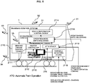
- FIG. 1 is a block diagram illustrating a schematic configuration of a train control system of the present invention.
- the train control system includes an on-board device 2 mounted on a train 1 and a ground device 3 installed on the ground.
- the on-board device 2 includes an on-board control system 21.
- the on-board control system 21 includes an on-board control device 211, an on-board wireless device 212, an on-board monitoring device 5 attached to the train 1 (vehicle), and a monitoring device. 2116 installed in an operator seat 2117.
- the on-board monitoring camera 5 and a device sensor 218 are provided at necessary locations outside and inside the train 1 (vehicle).
- the on-board monitoring device 5 includes a monitoring camera, the device sensor 218, and the like.
- the monitoring cameras include, for example, a front camera 51 that captures an image of the front of the train 1 traveling on a track 216, a rear camera 53 that captures an image of the rear of the train 1, a side camera 54 that captures an image of the periphery and sides of the train 1, a pantograph camera 52 that captures an image of the pantograph, and an in-vehicle camera 55 that captures an image of a door and the inside of the train 1 (vehicle).
- a front camera 51 that captures an image of the front of the train 1 traveling on a track 216
- a rear camera 53 that captures an image of the rear of the train 1
- a side camera 54 that captures an image of the periphery and sides of the train 1
- a pantograph camera 52 that captures an image of the pantograph
- an in-vehicle camera 55 that captures an image of a door and the inside of the train 1 (vehicle).
- the device sensor 218 includes, for example, an overhead line inspection sensor, a railway device inspection sensor, a track inspection sensor, and the like.
- the on-board control device 211 controls the on-board device 2 in response to a speed signal from the speed generator 214, a position signal from the on-board element 215, and the like.
- the on-board wireless device 212 is a device that wirelessly communicates data with the ground wireless device 312, and wirelessly transmits, for example, a camera video (a railroad crossing image and a railroad crossing position) captured by a monitoring camera of the on-board monitoring device 5 and sensor data detected by the device sensor 218 from the antenna 213 to the ground wireless device 312 of the ground device 3.
- a camera video a railroad crossing image and a railroad crossing position
- the monitoring device 2116 displays a camera video (a railroad crossing image and a railroad crossing position) and sensor data obtained by capturing an image of the occurrence of an obstruction at a railroad crossing with a camera.
- a passenger such as the operator or the conductor can detect the obstruction occurrence situation on the ground side.
- the ground device 3 includes a ground control system 31.
- the ground control system 31 includes a ground control device 311, a ground wireless device 312, a monitoring device 314, an operation command device 320, and the like.
- the ground control device 311 receives, for example, a camera image of the ground monitoring camera 6 installed on the ground side and sensor data of the device sensor 218 on the vehicle side, and outputs the camera image and the data to the ground wireless device 312 and the monitoring device 314.
- the monitoring camera of the ground monitoring device 6 includes, for example, a railway camera 62 that captures an image of a railway of the track 216, a railroad crossing camera 61 that captures an image of a railroad crossing, a home camera 63 that captures an image of a platform, and the like.
- the ground wireless device 312 wirelessly transmits a camera video (a railroad crossing image and a railroad crossing position) captured by the monitoring camera of the ground monitoring device 6 and sensor data detected by the device sensor 218 from the antenna 313 to the on-board wireless device 212 of the on-board device 2.
- the monitoring device 314 displays a camera video (a railroad crossing image and a railroad crossing position) captured by the monitoring camera of the ground monitoring device 6 and/or a camera video (a railroad crossing image and a railroad crossing position) captured by the monitoring camera of the on-board monitoring device 5 and sensor data detected by the various device sensors 218.
- an operation commander in the operation command station can check the obstruction occurrence situation on the ground side, that is, the presence or absence of an obstacle or a hindrance, and can issue an operation command according to the result.
- FIG. 2 is a block diagram illustrating a configuration example of the on-board control device 211 in the on-board device 2.
- the on-board control device 211 is a device that transmits and receives a notch command, vehicle information, and the like to and from the braking/driving control device 2115 (brake control device) of the on-board device 2 to control the braking/driving control device 2115.
- the on-board control device 211 includes a main controller (master controller) 2111, an ATO device 2112, an operation mode switching device 2113, a vehicle information control device 2114, and a braking/driving control device 2115.
- the automatic train operation operates in a state where a safety device (Automatic Train Control (ATC)) is provided.
- the ATO has a function of performing traveling from the departure to the stop of the train by adding functions such as departure control (control from the stop of the train at a platform to the departure after opening and closing of the door), regular operation control (control of performing acceleration/deceleration of a train and constant speed control, and then traveling to the next station in a predetermined time), and a home position stop control (control of automatically decelerate and stop the train at a predetermined position of a platform) based on the ATC device.
- departure control control from the stop of the train at a platform to the departure after opening and closing of the door
- regular operation control control of performing acceleration/deceleration of a train and constant speed control, and then traveling to the next station in a predetermined time
- a home position stop control control of automatically decelerate and stop the train at a predetermined position of a platform
- the master controller 2111 and the ATO device 2112 output a braking/driving command (notch command or torque command) including a braking/driving force based on the speed signal and the position signal, and control the output/speed of the train 1 (vehicle) via the braking/driving control device 2115 based on the vehicle information (operation pattern, schedule information) of the train 1 in the vehicle information control device 2114.
- a braking/driving command notch command or torque command
- a braking/driving force based on the speed signal and the position signal
- the master controller 2111 is, for example, a switch device that manually performs powering, constant speed or coasting, braking, and stopping of the train 1 when the operator operates the start button.
- the ATO device 2112 automatically performs powering, constant speed or coasting, braking, and stopping of the train 1 in response to an automatic operation command from the ATO central system 316 of the ground device 3.
- the operation mode switching device 2113 is a device that switches the master controller 2111 and the ATO device 2112 in response to the operation mode switching command transmitted from the ground device 3, that is, switches the operation mode of the train 1 to the manual mode or the automatic mode.
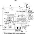
- FIG. 3 is a block diagram illustrating a configuration example of the ground control system 31 in the ground device 3.
- the ground control system 31 includes a train -detection device 318, an interlocking device 319, an operation management system 315, an ATO central system 316, a monitoring central system 317, the monitoring device 314 described above, an operation command device 320 including an operation command unit, and the like.
- the train detection device 318 When the train 1 approaches a preceding train (not illustrated), for example, the train detection device 318 outputs train detection information (drop/boost) indicating the position of each train.
- train detection information drop/boost
- the interlocking device 319 changes the point to a predetermined direction in response to the request for course setting, and when there is no other train (vehicle) on the course, the interlocking device displays a progress (green signal) meaning permission on the traffic light to guarantee the safety of train operation in the station, and outputs the train detection information detected by the train detection device 318 to the ground control device 311.
- the ground control device 311 calculates a stop limit position based on information such as the train position and the stop limit position received by the ground wireless device 312 and the train detection of the interlocking device 319 and the travel section stored therein, and transmits the stop limit position to the on-board device 2 via the antenna 313 of the ground wireless device 312.
- the ground wireless device 312 transmits and receives various types of information to and from the on-board device 2 via a wireless base station (not illustrated).
- the operation management system 315 manages the operation of the train 1, and is a device that automatically controls a course via an interlocking device at each station in accordance with a planned operation schedule, includes a means for acquiring information on a presence position of the train, and issues a command such as changing an evacuation order at a station when operation is disrupted.
- the ATO central system 316 is a device that operates in the presence of a safety device (ATC device) in response to a command from an operation command unit of the operation command device 320 by an operation of an operation commander, and issues a command of traveling from departure to stop of a so-called train 1, which commands functions such as departure control (control from the stop of the train at the platform to the departure after opening and closing of the door), regular operation control (control of performing acceleration/deceleration of a train and constant speed control, and then traveling to the next station in a predetermined time), and a home position stop control (control of automatically decelerate and stop the train at a predetermined position of a platform).
- ATC device safety device
- the monitoring central system 317 is a system including, for example, an obstacle/hindrance detection device 3171 that receives a camera image from a monitoring camera of the ground monitoring device 6 and sensor data from various device sensors 218, monitors the presence or absence of an obstacle (people, objects, cars, and the like) that obstructs traveling of the train or the presence or absence of the hindrance occurrence (device failure), and outputs the result to the monitoring device 314 and the ground wireless device 312, and a storage device 3172 that stores a camera video and the like.
- an obstacle/hindrance detection device 3171 that receives a camera image from a monitoring camera of the ground monitoring device 6 and sensor data from various device sensors 218, monitors the presence or absence of an obstacle (people, objects, cars, and the like) that obstructs traveling of the train or the presence or absence of the hindrance occurrence (device failure), and outputs the result to the monitoring device 314 and the ground wireless device 312, and a storage device 3172 that stores a camera video and the like
- the commander of the ground-side operation command station can determine the presence or absence of an obstacle/hindrance based on a camera video (a railroad crossing image and a railroad crossing position) and monitor data monitored by the monitoring device 314, and can command the ground side to issue an operation command (an operation mode, an operation mode change, or the like) according to the result.
- the operation management system 315, the ATO central system 316, and the monitoring central system 317 are configured to operate in conjunction with each other.
- the monitoring device 314, the operation management system 315, the ATO central system 316, the monitoring central system 317, and the operation command device 320 constitute an operation command system in the operation command center.
- FIG. 4 is a flowchart for describing a processing procedure for notifying the on-board side of an obstruction occurrence situation including an obstruction occurrence detection result and an obstruction occurrence place when the obstruction occurrence is detected on the ground side in the train control system.
- the monitoring central system 317 receives a camera image captured by a monitoring camera installed in a blind place (railroad crossing) and monitors an obstacle and a hindrance.
- Step S3112 The monitoring device 314 displays a camera image (railroad crossing image).
- Step S3113 In the ground-side operation command system, for example, the operation commander checks a camera video (camera image) and an obstacle detection result of the train that has detected an obstacle (people, objects, cars, and the like) that obstructs traveling of the train 1 and the hindrance occurrence (device failure) based on the monitor screen of the monitoring device 314, and determines whether there is an obstacle or a hindrance.
- the operation commander checks a camera video (camera image) and an obstacle detection result of the train that has detected an obstacle (people, objects, cars, and the like) that obstructs traveling of the train 1 and the hindrance occurrence (device failure) based on the monitor screen of the monitoring device 314, and determines whether there is an obstacle or a hindrance.
- the presence or the absence of an obstacle or a hindrance may be automatically determined by the obstacle/hindrance detection device instead of the commander.
- Step S3114 When determining that there is an obstacle in the railroad crossing, the ATO central system 316 transmits a camera image (railroad crossing image) showing the railroad crossing with the obstacle and a railroad crossing position (railroad crossing ID) to the on-board device 2 on the vehicle side via the ground wireless device 312.
- the camera image (railroad crossing image) and the railroad crossing position (railroad crossing ID) notify the on-board device of the ground field situation directly from a camera, a sensor, or the like installed on the ground side, or via the ground device.
- This notification is performed by a method of filtering the trains to be notified or a method of simultaneously notifying surrounding integrated trains based on the positions of the respective trains.
- the ATO central system 316 specifies the train 1 traveling in front of the railroad crossing based on the grasped information on the on-track position of the train and the information on the railroad crossing position, and transmits the camera image and the information on the railroad crossing position to the train 1.
- the information to be transmitted to the train may be a camera image (railroad crossing image) and a railroad crossing position (railroad crossing ID), but it is not always necessary to transmit the camera image as it is, and a determination result on the presence or the absence of an obstacle and information on the railroad crossing position may be transmitted.
- Step S3115 The ATO central system 316 transmits a camera image (railroad crossing image) showing a railroad crossing with an obstacle and a railroad crossing position (railroad crossing ID) via the ground wireless device 312 according to the train 1 (vehicle) and the railroad crossing position, that is, to another train 1' (vehicle) close to the obstruction occurrence place, for example, a following train or an oncoming train.
- a camera image showing a railroad crossing with an obstacle and a railroad crossing position (railroad crossing ID) via the ground wireless device 312 according to the train 1 (vehicle) and the railroad crossing position, that is, to another train 1' (vehicle) close to the obstruction occurrence place, for example, a following train or an oncoming train.
- an obstacle or an image itself captured by the monitoring camera while the train 1 is traveling may be transmitted to another train 1' via the ground device 3 or between trains without passing through the ground device, and may be notified.
- Step S3116 The monitoring device 2116 in the on-board device 2 on the on-board side displays the camera image (railroad crossing image) and the railroad crossing position (railroad crossing ID) transmitted from the ground device 3 on the ground side.
- the operator or the passenger can check the obstruction occurrence situation in the railroad crossing.
- an obstacle is detected, displayed, and determined on the vehicle upper side, and the train 1 is controlled in response to the obstacle. Only the configuration and steps changed from Embodiment 1 will be described below with reference to FIGS. 5 to 7 .
- FIG. 5 is a block diagram illustrating a configuration example of an on-board control system in Embodiment 2.
- An on-board control system 21 further includes an obstacle detection device 2118.
- the obstacle detection device 2118 receives a railroad crossing image and a railroad crossing ID (position) on the ground side, and outputs the image to the monitoring device 2116.
- the monitoring device 2116 displays and monitors a railroad crossing image and a railroad crossing ID (position) . Thus, it is possible to detect an obstacle on the vehicle side.
- FIG. 6 is a block diagram illustrating a configuration example of a ground control system in the ground device in Embodiment 2.
- the monitoring central system 317 can omit the obstacle/hindrance detection device 3171.
- FIG. 7 is a flowchart for explaining a processing procedure of detecting and displaying an occurrence of an obstruction on the on-board side in the train control system in Embodiment 2.
- Step S4111 The obstacle detection device 2118 of the on-board control system 21 receives a camera image captured by a monitoring camera installed at a place (railroad crossing) with poor visibility, and monitors an obstacle and a hindrance.
- Step S4112 When the obstacle detection device 2118 determines that there is an obstacle in the railroad crossing, the on-board control system 21 transmits a camera image (railroad crossing image) showing the railroad crossing with the obstacle and a railroad crossing position (railroad crossing ID) to the ground device 3 on the ground side via the on-board wireless device 212.
- a camera image showing the railroad crossing with the obstacle
- a railroad crossing position (railroad crossing ID)
- Step S4113 The on-board control system 21 transmits, via the on-board wireless device 212, a camera image (railroad crossing image) showing a railroad crossing with an obstacle and a railroad crossing position (railroad crossing ID) according to the train 1 (vehicle) and the railroad crossing position, that is, also to another train 1' (vehicle) close to the obstruction occurrence place, for example, a following train or an oncoming train.
- a camera image showing a railroad crossing with an obstacle and a railroad crossing position (railroad crossing ID) according to the train 1 (vehicle) and the railroad crossing position, that is, also to another train 1' (vehicle) close to the obstruction occurrence place, for example, a following train or an oncoming train.
- Step S4114 In the obstacle detection device 2118 of the on-board control system 21, for example, the operation commander checks a camera video (camera image) and a hindrance detection result of the train that has detected an obstacle (people, objects, cars, and the like) that obstructs traveling of the train 1 or a hindrance occurrence (device failure) based on the monitor screen of the monitoring device 314, and determines whether there is an obstacle or a hindrance.
- the presence or the absence of an obstacle or a hindrance may be automatically determined by the obstacle/hindrance detection device instead of the commander.
- Step S4115 The monitoring device 2116 in the on-board control system 21 on the on-board side displays the camera image (railroad crossing image) and the railroad crossing position (railroad crossing ID) received by the obstacle detection device 2118.
- the operator or the passenger can check the obstruction occurrence situation in the railroad crossing.
- the presence or absence of the obstacle/hindrance is determined by the operation commander in the ground-side operation command system.
- the determination may be automatically performed using an image recognition technology or an artificial intelligence (AI) technology. In this case, the operation commander becomes unnecessary.
- AI artificial intelligence
- the present invention is not limited to the above-described embodiment, and various modifications may be provided.
- the above embodiments are described in detail in order to explain the present invention in an easy-to-understand manner, and the above examples are not necessarily limited to a case including all the described configurations.
Landscapes
- Engineering & Computer Science (AREA)
- Mechanical Engineering (AREA)
- Multimedia (AREA)
- Signal Processing (AREA)
- Life Sciences & Earth Sciences (AREA)
- Sustainable Development (AREA)
- Sustainable Energy (AREA)
- Power Engineering (AREA)
- Transportation (AREA)
- Train Traffic Observation, Control, And Security (AREA)
- Electric Propulsion And Braking For Vehicles (AREA)
- Closed-Circuit Television Systems (AREA)
Abstract
Description
- The present invention relates to a train control system.
- In the related art, as a technique for supporting an operation of a train, for example, there is a technique disclosed in
JP 2017-87978 A - PTL 1:
JP 2017-87978 A - In
PTL 1, when the train reaches a position before the railroad crossing, the ground device collects in-railroad crossing information (image) captured by the image pickup device. Then, the collected in-railroad crossing information is transmitted from the ground device to the on-board device and displayed on the display device of the on-board device, so that the operator can check the situation in the railroad crossing by this display. However, inPTL 1, it is not assumed that, when an obstacle that obstructs traveling of the train or a failure of various devices on a vehicle is detected from the image captured by the image pickup device, the remote control of the train from the ground is centrally managed in accordance with the presence or absence of the obstacle or a hindrance. Therefore, the invention inPTL 1 has only an effect that an operator can display and check the in-railroad crossing information (image) on the vehicle. - In addition, in the related art, the fact is that, when the train passes through a place where the operator cannot see, the operator sounds a horn or the like to inform the surroundings of the passage of the train. Even if the operator can display and check the situation in the railroad crossing with an image, it is difficult for the operator to reliably detect the presence or absence of the obstacle or hindrance only with the image information. Furthermore, means for giving information to the operator is not considered for a situation in a place such as a curve with poor visibility other than a railroad crossing and a station platform.
- Therefore, an object of the present invention is to provide a technique capable of displaying and checking an image and position information of a monitoring camera on an on-board side in a manner that the monitoring camera and a sensor (such as a millimeter wave or a LIDAR) is installed around a railway track on which a train travels, particularly at a place where an operator cannot see, for example, a curve, a railroad crossing, a station platform, or the like, so as to detect an obstacle or a hindrance on a ground side based on a camera video (or a camera image) obtained by the monitoring camera or the sensor, and, when an obstacle or a hindrance can be detected, the camera video (or an obstruction detection result) and a position (equipment ID) of the monitoring camera that captures an image of the obstacle or the hindrance are transmitted to the on-board side.
- In order to achieve the above object, one of the representative train control systems of the present invention is a train control system including: a monitoring camera that is installed on a ground and/or on a vehicle and captures an image around a track on which a train travels or on a railway; a ground device; and an on-board device.
- The ground device includes
- an obstacle detection device that collects a camera video captured by the monitoring camera and detects presence or absence of an obstacle based on the collected camera video, and
- a ground wireless device that, when the obstacle detection device detects the obstacle, transmits at least any information of the camera video of the monitoring camera that detects the obstacle and an obstacle detection result, and position information indicating a place of the monitoring camera that detects the obstacle, to the on-board device.
- The on-board device includes an on-board wireless device that receives at least the any information of the camera video and the obstacle detection result, and the position information of the monitoring camera that detects the obstacle, which are transmitted from the ground wireless device of the ground device, and
a monitoring device that displays at least the any information of the camera video and the obstacle detection result, and the position information indicating an obstruction occurrence place, which are received by the on-board wireless device. - The monitoring device is enabled to check a field situation before the train approaches the obstruction/hindrance occurrence place.
- When there is another train (vehicle) close to the train (vehicle) in accordance with the train (vehicle) and the position information, the ground device further transmits a monitoring camera video and the position information to an on-board device of the close other train (vehicle) to call attention to a following train and an oncoming train.
- In order to achieve the above object, another of the representative train control systems of the present invention is a train control system including: a monitoring camera that is installed on a ground and/or on a vehicle and captures an image around a track on which a train travels or on a railway; a ground device; and an on-board device.
- The ground device includes
a ground wireless device that transmits, to the on-board device, a camera video captured by a monitoring camera and position information indicating a place of the monitoring camera. - The on-board device includes
- an on-board wireless device that receives the camera video transmitted from the ground wireless device of the ground device and the position information of the monitoring camera that detects an obstacle,
- an obstacle detection device that detects presence or absence of the obstacle based on the camera video transmitted from the ground wireless device of the ground device, and
- a monitoring device that, when the obstacle detection device detects the obstacle, displays at least any information of the camera video used to detect the obstacle and an obstacle detection result, and the position information indicating the place of the monitoring camera, which is transmitted from the ground wireless device.
- The monitoring device is enabled to check a field situation before the train approaches an obstruction/hindrance occurrence place.
- According to the present invention, it is possible to provide information regarding an obstacle on the ground side to an operator on the vehicle.
- For example, in the case of an operator or the like on the train side, it is possible to accurately and quickly check, on traveling of the train, entry and stay of an object that obstructs or hinders the train on the ground side, for example, a person, a car, an animal, and the like after crossing is blocked, a railroad crossing barrier (taking a signal directly from a railroad crossing, a lighting status of a special signal light emitter, or the like), an emergency push button status (taking a signal directly from a button, or a lighting status of a special signal light emitter, or the like), a fall at a station platform, wobble, congestion at a station platform, or the like, and it is possible to perform safer operation management.
- Objects, configurations, and advantageous effects other than those described above will be clarified by the descriptions of the following embodiments.
-
- [
FIG. 1] FIG. 1 is a block diagram illustrating a schematic configuration ofEmbodiment 1 in a train control system of the present invention. - [
FIG. 2] FIG. 2 is a block diagram illustrating a configuration example of an on-board control system in an on-board device inEmbodiment 1. - [
FIG. 3] FIG. 3 is a block diagram illustrating a configuration example of a ground control system in a ground device inEmbodiment 1. - [
FIG. 4] FIG. 4 is a flowchart for describing a processing procedure for notifying an on-board side of an obstruction occurrence situation including an obstruction occurrence detection result and an obstruction occurrence place when the obstruction occurrence is detected on the ground side in the train control system inEmbodiment 1. - [
FIG. 5] FIG. 5 is a block diagram illustrating a configuration example of an on-board control system inEmbodiment 2 in the train control system of the present invention. - [
FIG. 6] FIG. 6 is a block diagram illustrating a configuration example of a ground control system in a ground device inEmbodiment 2. - [
FIG. 7] FIG. 7 is a flowchart for explaining a processing procedure of detecting and displaying an occurrence of an obstruction on the on-board side in the train control system inEmbodiment 2. - Hereinafter, embodiments of the present invention will be described with reference to the drawings.
- First, in the following embodiments, a case where an obstruction or a hindrance occurring on the ground side is detected refers to a case where a railroad crossing on a track, a station platform around the track, or an operator has no visibility, that is, a case where an obstacle or an obstacle is detected by a monitoring camera or a sensor installed in a place where visibility is poor on the railway, for example, a curve of the track, a station platform, or the like. Detection of the occurrence of an obstruction or a hindrance may be performed on the ground side or on the vehicle upper side.
- An example in which an obstacle at a railroad crossing is captured by a monitoring camera will be described below.
-
FIG. 1 is a block diagram illustrating a schematic configuration of a train control system of the present invention. - The train control system includes an on-
board device 2 mounted on atrain 1 and aground device 3 installed on the ground. - The on-
board device 2 includes an on-board control system 21. The on-board control system 21 includes an on-board control device 211, an on-boardwireless device 212, an on-board monitoring device 5 attached to the train 1 (vehicle), and a monitoring device. 2116 installed in anoperator seat 2117. The on-board monitoring camera 5 and adevice sensor 218 are provided at necessary locations outside and inside the train 1 (vehicle). - The on-
board monitoring device 5 includes a monitoring camera, thedevice sensor 218, and the like. - The monitoring cameras include, for example, a
front camera 51 that captures an image of the front of thetrain 1 traveling on atrack 216, arear camera 53 that captures an image of the rear of thetrain 1, aside camera 54 that captures an image of the periphery and sides of thetrain 1, apantograph camera 52 that captures an image of the pantograph, and an in-vehicle camera 55 that captures an image of a door and the inside of the train 1 (vehicle). - The
device sensor 218 includes, for example, an overhead line inspection sensor, a railway device inspection sensor, a track inspection sensor, and the like. - The on-
board control device 211 controls the on-board device 2 in response to a speed signal from thespeed generator 214, a position signal from the on-board element 215, and the like. - The on-board
wireless device 212 is a device that wirelessly communicates data with the groundwireless device 312, and wirelessly transmits, for example, a camera video (a railroad crossing image and a railroad crossing position) captured by a monitoring camera of the on-board monitoring device 5 and sensor data detected by thedevice sensor 218 from the antenna 213 to the groundwireless device 312 of theground device 3. - The
monitoring device 2116 displays a camera video (a railroad crossing image and a railroad crossing position) and sensor data obtained by capturing an image of the occurrence of an obstruction at a railroad crossing with a camera. Thus, a passenger such as the operator or the conductor can detect the obstruction occurrence situation on the ground side. - The
ground device 3 includes a ground control system 31. The ground control system 31 includes aground control device 311, aground wireless device 312, amonitoring device 314, an operation command device 320, and the like. - The
ground control device 311 receives, for example, a camera image of theground monitoring camera 6 installed on the ground side and sensor data of thedevice sensor 218 on the vehicle side, and outputs the camera image and the data to theground wireless device 312 and themonitoring device 314. - The monitoring camera of the
ground monitoring device 6 includes, for example, arailway camera 62 that captures an image of a railway of thetrack 216, arailroad crossing camera 61 that captures an image of a railroad crossing, ahome camera 63 that captures an image of a platform, and the like. - The
ground wireless device 312 wirelessly transmits a camera video (a railroad crossing image and a railroad crossing position) captured by the monitoring camera of theground monitoring device 6 and sensor data detected by thedevice sensor 218 from theantenna 313 to the on-board wireless device 212 of the on-board device 2. - The
monitoring device 314 displays a camera video (a railroad crossing image and a railroad crossing position) captured by the monitoring camera of theground monitoring device 6 and/or a camera video (a railroad crossing image and a railroad crossing position) captured by the monitoring camera of the on-board monitoring device 5 and sensor data detected by thevarious device sensors 218. Thus, an operation commander in the operation command station can check the obstruction occurrence situation on the ground side, that is, the presence or absence of an obstacle or a hindrance, and can issue an operation command according to the result. -
FIG. 2 is a block diagram illustrating a configuration example of the on-board control device 211 in the on-board device 2. - The on-
board control device 211 is a device that transmits and receives a notch command, vehicle information, and the like to and from the braking/driving control device 2115 (brake control device) of the on-board device 2 to control the braking/driving control device 2115. - The on-
board control device 211 includes a main controller (master controller) 2111, anATO device 2112, an operation mode switching device 2113, a vehicleinformation control device 2114, and a braking/driving control device 2115. - The automatic train operation (ATO) operates in a state where a safety device (Automatic Train Control (ATC)) is provided. The ATO has a function of performing traveling from the departure to the stop of the train by adding functions such as departure control (control from the stop of the train at a platform to the departure after opening and closing of the door), regular operation control (control of performing acceleration/deceleration of a train and constant speed control, and then traveling to the next station in a predetermined time), and a home position stop control (control of automatically decelerate and stop the train at a predetermined position of a platform) based on the ATC device. For example, when the operator presses a start instruction button, the train automatically performs power running, constant speed or coasting, braking, and fixed point stop of the train.
- The
master controller 2111 and theATO device 2112 output a braking/driving command (notch command or torque command) including a braking/driving force based on the speed signal and the position signal, and control the output/speed of the train 1 (vehicle) via the braking/driving control device 2115 based on the vehicle information (operation pattern, schedule information) of thetrain 1 in the vehicleinformation control device 2114. - In addition, the
master controller 2111 is, for example, a switch device that manually performs powering, constant speed or coasting, braking, and stopping of thetrain 1 when the operator operates the start button. - The
ATO device 2112 automatically performs powering, constant speed or coasting, braking, and stopping of thetrain 1 in response to an automatic operation command from the ATOcentral system 316 of theground device 3. - The operation mode switching device 2113 is a device that switches the
master controller 2111 and theATO device 2112 in response to the operation mode switching command transmitted from theground device 3, that is, switches the operation mode of thetrain 1 to the manual mode or the automatic mode. -
FIG. 3 is a block diagram illustrating a configuration example of the ground control system 31 in theground device 3. - In addition to the
ground control device 311 and theground wireless device 312, the ground control system 31 includes a train -detection device 318, an interlockingdevice 319, anoperation management system 315, an ATOcentral system 316, a monitoringcentral system 317, themonitoring device 314 described above, an operation command device 320 including an operation command unit, and the like. - When the
train 1 approaches a preceding train (not illustrated), for example, thetrain detection device 318 outputs train detection information (drop/boost) indicating the position of each train. - The interlocking
device 319 changes the point to a predetermined direction in response to the request for course setting, and when there is no other train (vehicle) on the course, the interlocking device displays a progress (green signal) meaning permission on the traffic light to guarantee the safety of train operation in the station, and outputs the train detection information detected by thetrain detection device 318 to theground control device 311. - The
ground control device 311 calculates a stop limit position based on information such as the train position and the stop limit position received by theground wireless device 312 and the train detection of the interlockingdevice 319 and the travel section stored therein, and transmits the stop limit position to the on-board device 2 via theantenna 313 of theground wireless device 312. - The
ground wireless device 312 transmits and receives various types of information to and from the on-board device 2 via a wireless base station (not illustrated). - The
operation management system 315 manages the operation of thetrain 1, and is a device that automatically controls a course via an interlocking device at each station in accordance with a planned operation schedule, includes a means for acquiring information on a presence position of the train, and issues a command such as changing an evacuation order at a station when operation is disrupted. - The ATO
central system 316 is a device that operates in the presence of a safety device (ATC device) in response to a command from an operation command unit of the operation command device 320 by an operation of an operation commander, and issues a command of traveling from departure to stop of a so-calledtrain 1, which commands functions such as departure control (control from the stop of the train at the platform to the departure after opening and closing of the door), regular operation control (control of performing acceleration/deceleration of a train and constant speed control, and then traveling to the next station in a predetermined time), and a home position stop control (control of automatically decelerate and stop the train at a predetermined position of a platform). - The monitoring
central system 317 is a system including, for example, an obstacle/hindrance detection device 3171 that receives a camera image from a monitoring camera of theground monitoring device 6 and sensor data fromvarious device sensors 218, monitors the presence or absence of an obstacle (people, objects, cars, and the like) that obstructs traveling of the train or the presence or absence of the hindrance occurrence (device failure), and outputs the result to themonitoring device 314 and theground wireless device 312, and astorage device 3172 that stores a camera video and the like. - The commander of the ground-side operation command station can determine the presence or absence of an obstacle/hindrance based on a camera video (a railroad crossing image and a railroad crossing position) and monitor data monitored by the
monitoring device 314, and can command the ground side to issue an operation command (an operation mode, an operation mode change, or the like) according to the result. - The
operation management system 315, the ATOcentral system 316, and the monitoringcentral system 317 are configured to operate in conjunction with each other. In addition, themonitoring device 314, theoperation management system 315, the ATOcentral system 316, the monitoringcentral system 317, and the operation command device 320 constitute an operation command system in the operation command center. -
FIG. 4 is a flowchart for describing a processing procedure for notifying the on-board side of an obstruction occurrence situation including an obstruction occurrence detection result and an obstruction occurrence place when the obstruction occurrence is detected on the ground side in the train control system. - The operation based on the flowchart in
FIG. 4 is as follows. - Step S3111:
- The monitoring
central system 317 receives a camera image captured by a monitoring camera installed in a blind place (railroad crossing) and monitors an obstacle and a hindrance. - Step S3112:
Themonitoring device 314 displays a camera image (railroad crossing image). - Step S3113:
In the ground-side operation command system, for example, the operation commander checks a camera video (camera image) and an obstacle detection result of the train that has detected an obstacle (people, objects, cars, and the like) that obstructs traveling of thetrain 1 and the hindrance occurrence (device failure) based on the monitor screen of themonitoring device 314, and determines whether there is an obstacle or a hindrance. - Here, the presence or the absence of an obstacle or a hindrance may be automatically determined by the obstacle/hindrance detection device instead of the commander.
- Step S3114:
When determining that there is an obstacle in the railroad crossing, the ATOcentral system 316 transmits a camera image (railroad crossing image) showing the railroad crossing with the obstacle and a railroad crossing position (railroad crossing ID) to the on-board device 2 on the vehicle side via theground wireless device 312. - The camera image (railroad crossing image) and the railroad crossing position (railroad crossing ID) notify the on-board device of the ground field situation directly from a camera, a sensor, or the like installed on the ground side, or via the ground device. This notification is performed by a method of filtering the trains to be notified or a method of simultaneously notifying surrounding integrated trains based on the positions of the respective trains.
- Here, when the ground field situation is notified to the on-board device via the ground device, the ATO
central system 316 specifies thetrain 1 traveling in front of the railroad crossing based on the grasped information on the on-track position of the train and the information on the railroad crossing position, and transmits the camera image and the information on the railroad crossing position to thetrain 1. The information to be transmitted to the train may be a camera image (railroad crossing image) and a railroad crossing position (railroad crossing ID), but it is not always necessary to transmit the camera image as it is, and a determination result on the presence or the absence of an obstacle and information on the railroad crossing position may be transmitted. - Step S3115:
The ATOcentral system 316 transmits a camera image (railroad crossing image) showing a railroad crossing with an obstacle and a railroad crossing position (railroad crossing ID) via theground wireless device 312 according to the train 1 (vehicle) and the railroad crossing position, that is, to another train 1' (vehicle) close to the obstruction occurrence place, for example, a following train or an oncoming train. - Here, an obstacle or an image itself captured by the monitoring camera while the
train 1 is traveling may be transmitted to another train 1' via theground device 3 or between trains without passing through the ground device, and may be notified. - Step S3116:
Themonitoring device 2116 in the on-board device 2 on the on-board side displays the camera image (railroad crossing image) and the railroad crossing position (railroad crossing ID) transmitted from theground device 3 on the ground side. Thus, the operator or the passenger can check the obstruction occurrence situation in the railroad crossing. - In the present embodiment, an obstacle is detected, displayed, and determined on the vehicle upper side, and the
train 1 is controlled in response to the obstacle. Only the configuration and steps changed fromEmbodiment 1 will be described below with reference toFIGS. 5 to 7 . -
FIG. 5 is a block diagram illustrating a configuration example of an on-board control system inEmbodiment 2. An on-board control system 21 further includes anobstacle detection device 2118. - The
obstacle detection device 2118 receives a railroad crossing image and a railroad crossing ID (position) on the ground side, and outputs the image to themonitoring device 2116. Themonitoring device 2116 displays and monitors a railroad crossing image and a railroad crossing ID (position) . Thus, it is possible to detect an obstacle on the vehicle side. -
FIG. 6 is a block diagram illustrating a configuration example of a ground control system in the ground device inEmbodiment 2. When an obstacle is detected on the vehicle upper side, the monitoringcentral system 317 can omit the obstacle/hindrance detection device 3171. -
FIG. 7 is a flowchart for explaining a processing procedure of detecting and displaying an occurrence of an obstruction on the on-board side in the train control system inEmbodiment 2. - Step S4111:
Theobstacle detection device 2118 of the on-board control system 21 receives a camera image captured by a monitoring camera installed at a place (railroad crossing) with poor visibility, and monitors an obstacle and a hindrance. - Step S4112:
When theobstacle detection device 2118 determines that there is an obstacle in the railroad crossing, the on-board control system 21 transmits a camera image (railroad crossing image) showing the railroad crossing with the obstacle and a railroad crossing position (railroad crossing ID) to theground device 3 on the ground side via the on-board wireless device 212. - Step S4113:
The on-board control system 21 transmits, via the on-board wireless device 212, a camera image (railroad crossing image) showing a railroad crossing with an obstacle and a railroad crossing position (railroad crossing ID) according to the train 1 (vehicle) and the railroad crossing position, that is, also to another train 1' (vehicle) close to the obstruction occurrence place, for example, a following train or an oncoming train. - Step S4114:
In theobstacle detection device 2118 of the on-board control system 21, for example, the operation commander checks a camera video (camera image) and a hindrance detection result of the train that has detected an obstacle (people, objects, cars, and the like) that obstructs traveling of thetrain 1 or a hindrance occurrence (device failure) based on the monitor screen of themonitoring device 314, and determines whether there is an obstacle or a hindrance. Here, the presence or the absence of an obstacle or a hindrance may be automatically determined by the obstacle/hindrance detection device instead of the commander. - Step S4115:
Themonitoring device 2116 in the on-board control system 21 on the on-board side displays the camera image (railroad crossing image) and the railroad crossing position (railroad crossing ID) received by theobstacle detection device 2118. Thus, the operator or the passenger can check the obstruction occurrence situation in the railroad crossing. - In the present embodiment described above, the presence or absence of the obstacle/hindrance is determined by the operation commander in the ground-side operation command system. However, for example, in the monitoring
central system 317, the determination may be automatically performed using an image recognition technology or an artificial intelligence (AI) technology. In this case, the operation commander becomes unnecessary. - Note that, the present invention is not limited to the above-described embodiment, and various modifications may be provided. For example, the above embodiments are described in detail in order to explain the present invention in an easy-to-understand manner, and the above examples are not necessarily limited to a case including all the described configurations.
-
- 1 train (vehicle)
- 2 on-board device
- 21 on-board control system
- 211 on-board control device
- 212 on-board wireless device
- 2111 master controller
- 2112 ATO device
- 2113 operation mode switching device
- 2114 vehicle information control device
- 2115 braking/driving control device
- 3 ground device
- 31 ground control system
- 311 ground control device
- 312 ground wireless device
- 314 monitoring device
- 315
operation management system 316 ATO central system - 317 monitoring central system
- 3171 obstacle/hindrance detection device
- 318 train detection device
- 319 interlocking device
- 320 operation command device
- 5 on-board monitoring device
- 6 ground monitoring device
Claims (11)
- A train control system comprising:a monitoring camera that is installed on a ground and/or on a vehicle and captures an image around a track on which a train travels or on a railway; a ground device; and an on-board device, whereinthe ground device includesan obstacle detection device that collects a camera video captured by the monitoring camera and detects presence or absence of an obstacle/hindrance based on the collected camera video, anda ground wireless device that, when the obstacle detection device detects the obstacle/hindrance, transmits at least any information of the camera video of the monitoring camera that detects the obstacle/hindrance and an obstacle/hindrance detection result, and position information indicating an obstruction/hindrance occurrence place, to the on-board device,the on-board device includesan on-board wireless device that receives at least the any information of the camera video and the obstacle/hindrance detection result, and the position information indicating the obstruction/hindrance occurrence place, which are transmitted from the ground wireless device of the ground device, anda monitoring device that displays at least the any information of the camera video and the obstacle/hindrance detection result, and the position information indicating the obstruction/hindrance occurrence place, which are received by the on-board wireless device, andthe monitoring device is enabled to check a field situation before the train approaches the obstruction/hindrance occurrence place.
- The train control system according to claim 1, wherein the monitoring camera includesone or more of a railway camera that captures an image of a track railway, a railroad crossing camera that captures an image of an inside of a railroad crossing, and a home camera that captures an image of a platform, the railway camera, the railroad crossing camera, and the home camera being installed on a ground, and/orone or more of a front camera that captures an image of a front of the train traveling on the track, a rear camera that captures an image of a rear of the train, a side camera that captures an image of a periphery and a side of the train, a pantograph camera that captures an image of a pantograph, and an in-vehicle camera that captures an image of a door of the train or an inside of the vehicle, the front camera, the rear camera, the side camera, the pantograph camera, and the in-vehicle camera being installed on the vehicle.
- The train control system according to claim 1 or 2, whereinan obstacle or an image itself captured by the monitoring camera during traveling of the train is transmitted to another train via the ground device or between trains without passing through the ground device,so as to be notified.
- A train control system comprising:a monitoring camera that is installed on a ground and/or on a vehicle and captures an image around a track on which a train travels or on a railway; a ground device; and an on-board device, whereinthe ground device includes a ground wireless device that transmits, to the on-board device, a camera video captured by a monitoring camera and position information indicating a place of the monitoring camera,the on-board device includesan on-board wireless device that receives the camera video transmitted from the ground wireless device of the ground device and the position information of the monitoring camera that detects an obstacle,an obstacle detection device that detects presence or absence of the obstacle based on the camera video transmitted from the ground wireless device of the ground device, anda monitoring device that, when the obstacle detection device detects the obstacle, displays at least any information of the camera video used to detect the obstacle and an obstacle detection result, and the position information indicating the place of the monitoring camera, which is transmitted from the ground wireless device, andthe monitoring device is enabled to check a field situation before the train approaches an obstruction/hindrance occurrence place.
- The train control system according to claim 1 or 4, wherein,when there is another train close to the train in accordance with the train and the position information,the ground device further transmits a monitoring camera video and the position information to an on-board device of the close other train to call attention to a following train and an oncoming train.
- The train control system according to claim 1 or 5, whereinthe ground device further includes a monitoring device that displays the camera video captured by the monitoring camera, andthe monitoring device is enabled to check a field situation before the train approaches an obstruction/hindrance occurrence place.
- The train control system according to any one of claims 1 to 6, wherein the monitoring camera includes one or more of a railway camera, a railroad crossing camera, and a home camera.
- A train control system comprising:a monitoring camera that is installed on a ground, captures an image of an obstacle that obstructs or hinders traveling of a train, and outputs a camera video;a ground device that includes a monitoring device that receives and displays the camera video captured by the monitoring camera and position information indicating an obstruction occurrence place; andan on-board device that includes a monitoring device that receives and displays the camera video transmitted from the ground device and the position information indicating the obstruction occurrence place,wherein, when an obstacle/hindrance that may obstruct/hinder traveling of the train is detected based on the camera video captured by the monitoring camera, the ground device transmits the camera video and information indicating a position indicating an obstruction occurrence place, to an on-board device of a train close to the obstruction occurrence place,the on-board device causes the camera video and position information indicating the obstruction occurrence place, which are transmitted from the ground device, to be displayed on the monitoring device, andthe monitoring device is enabled to check a field situation before the train approaches an obstruction/hindrance occurrence place.
- The train control system according to claim 8, wherein the monitoring camera includes
one or more of a railway camera, a railroad crossing camera, and a home camera. - The train control system according to claim 8, whereinthe monitoring camera is installed on the ground, captures an image of a place that cannot be seen from an operator seat, and outputs a camera video obtained by capturing an image of the place that cannot be seen from an operator seat and information indicating a position indicating an obstruction occurrence place,the ground device includesthe monitoring device that receives and displays the camera video captured by the monitoring camera and the position information indicating the obstruction occurrence place,an obstacle detection device that has a function of determining presence or absence of an obstacle from the camera video, anda ground wireless device that transmits the camera video of the monitoring camera and the information indicating the position to an on-board wireless device,the on-board device includesan on-board monitor device that displays the camera video of the monitoring camera and the information indicating the position, which are received by the on-board wireless device, andthe on-board wireless device that receives the camera video of the monitoring camera and the information indicating the position, which are transmitted from the ground device,when the obstacle detection device detects an obstacle, the ground device transmits the camera video of the monitoring camera that detects the obstacle and the information indicating the position, to a train present at a place close to the obstacle via the ground wireless device,the on-board device displays the camera video of the monitoring camera that detects the obstacle and the information indicating the position, which are transmitted from the ground device, andthe monitoring device is enabled to check a field situation before the train approaches an obstruction/hindrance occurrence place.
- The train control system according to claim 10, whereinthe place that cannot be seen from the operator seat is any one or more of a curve, a railroad crossing, and a vicinity of a door, andthe monitoring camera is any one or more of a railway camera, a railroad crossing camera, and a home camera.
Applications Claiming Priority (2)
| Application Number | Priority Date | Filing Date | Title |
|---|---|---|---|
| JP2019168111A JP7153000B2 (en) | 2019-09-17 | 2019-09-17 | train control system |
| PCT/JP2020/016712 WO2021053866A1 (en) | 2019-09-17 | 2020-04-16 | Train control system |
Publications (2)
| Publication Number | Publication Date |
|---|---|
| EP4032782A1 true EP4032782A1 (en) | 2022-07-27 |
| EP4032782A4 EP4032782A4 (en) | 2023-09-27 |
Family
ID=74877438
Family Applications (1)
| Application Number | Title | Priority Date | Filing Date |
|---|---|---|---|
| EP20864310.6A Pending EP4032782A4 (en) | 2019-09-17 | 2020-04-16 | TRAIN CONTROL SYSTEM |
Country Status (3)
| Country | Link |
|---|---|
| EP (1) | EP4032782A4 (en) |
| JP (1) | JP7153000B2 (en) |
| WO (1) | WO2021053866A1 (en) |
Cited By (1)
| Publication number | Priority date | Publication date | Assignee | Title |
|---|---|---|---|---|
| EP4403435A3 (en) * | 2022-12-30 | 2024-10-02 | Jui-Yuan Shih | Train forewarning braking system |
Families Citing this family (9)
| Publication number | Priority date | Publication date | Assignee | Title |
|---|---|---|---|---|
| CN112706805B (en) * | 2021-03-26 | 2021-09-10 | 交控科技股份有限公司 | Trackside equipment, track star chain system and train operation control system |
| CN113581252A (en) * | 2021-07-21 | 2021-11-02 | 南京苏莱瑞新技术有限公司 | Obstacle detection system based on multi-sensor fusion |
| CN113589305A (en) * | 2021-07-23 | 2021-11-02 | 广东智通睿新智能科技有限公司 | Railway platform clearance foreign matter detecting system |
| JP7841879B2 (en) | 2021-12-28 | 2026-04-07 | 株式会社京三製作所 | Ground equipment |
| CN114604300A (en) * | 2022-03-16 | 2022-06-10 | 天津津航计算技术研究所 | FAO remote driving system based on 5G technology |
| KR102623294B1 (en) * | 2022-03-31 | 2024-01-10 | 주식회사 가연테크 | System for measuring dynamic movement of railroad |
| CN115297297B (en) * | 2022-06-21 | 2024-09-03 | 卡斯柯信号有限公司 | A method for on-site demonstration of rail transit signal system based on live video broadcast |
| JP7731864B2 (en) * | 2022-12-09 | 2025-09-01 | 株式会社日立製作所 | On-board server and data transfer method |
| CN116279663A (en) * | 2023-04-19 | 2023-06-23 | 西北铁道电子股份有限公司 | Vehicle-mounted intelligent anti-collision alarm control equipment |
Family Cites Families (11)
| Publication number | Priority date | Publication date | Assignee | Title |
|---|---|---|---|---|
| JPH04266567A (en) * | 1991-02-21 | 1992-09-22 | Hitachi Denshi Ltd | Obstacle monitoring device |
| JP3022759B2 (en) * | 1996-02-26 | 2000-03-21 | 日本電気移動通信株式会社 | Railroad crossing monitoring system |
| JP2006232024A (en) * | 2005-02-23 | 2006-09-07 | Nec Corp | Safety monitoring system, safety device, and alarm device |
| JP4706315B2 (en) * | 2005-04-18 | 2011-06-22 | 株式会社ニコン | Vehicle driving support system |
| JP5096959B2 (en) * | 2008-02-26 | 2012-12-12 | 三菱電機株式会社 | Automatic train notification system |
| JP5559593B2 (en) | 2010-05-19 | 2014-07-23 | 株式会社日立国際電気 | Monitoring system |
| JP6336857B2 (en) * | 2014-08-27 | 2018-06-06 | 株式会社日立製作所 | Vehicle control system and vehicle control apparatus |
| JP6840422B2 (en) | 2015-11-10 | 2021-03-10 | 日本信号株式会社 | Train driving support system |
| JP6805328B2 (en) | 2017-03-23 | 2020-12-23 | 株式会社日立国際電気 | Monitoring system and monitoring method |
| JP7289184B2 (en) * | 2017-06-14 | 2023-06-09 | 日本信号株式会社 | Automatic train operation system |
| JP2019089373A (en) * | 2017-11-10 | 2019-06-13 | 日本信号株式会社 | Obstacle monitoring device and vehicle operation management system |
-
2019
- 2019-09-17 JP JP2019168111A patent/JP7153000B2/en active Active
-
2020
- 2020-04-16 WO PCT/JP2020/016712 patent/WO2021053866A1/en not_active Ceased
- 2020-04-16 EP EP20864310.6A patent/EP4032782A4/en active Pending
Cited By (2)
| Publication number | Priority date | Publication date | Assignee | Title |
|---|---|---|---|---|
| EP4403435A3 (en) * | 2022-12-30 | 2024-10-02 | Jui-Yuan Shih | Train forewarning braking system |
| US12522267B2 (en) | 2022-12-30 | 2026-01-13 | Jui Yuan SHIH | Train forewarning braking system |
Also Published As
| Publication number | Publication date |
|---|---|
| WO2021053866A1 (en) | 2021-03-25 |
| EP4032782A4 (en) | 2023-09-27 |
| JP2021045994A (en) | 2021-03-25 |
| JP7153000B2 (en) | 2022-10-13 |
Similar Documents
| Publication | Publication Date | Title |
|---|---|---|
| JP7153000B2 (en) | train control system | |
| US10618536B2 (en) | Method and system for managing specific events related to the movements of a guided vehicle | |
| JP5096959B2 (en) | Automatic train notification system | |
| CN109398424B (en) | Detection system for intrusion of non-communication vehicle | |
| KR102058940B1 (en) | Safety System for Worker in Railway Tunnel | |
| KR101654354B1 (en) | Railway signaling system using the Railway sensing unit | |
| KR20050062889A (en) | Train emergency control system and method using unexpected accident image detector | |
| KR101128978B1 (en) | Intelligence System for Accident Prevention at Railway Level Crossing and Train Brake Method | |
| KR101185079B1 (en) | The Method And Apparatus For Monitoring a Train And Railway Line | |
| KR100869835B1 (en) | Multi-sensor based platform monitoring system | |
| KR100876661B1 (en) | Image based platform monitoring system | |
| JP4706315B2 (en) | Vehicle driving support system | |
| CN114426044A (en) | Image-based train safe operation control system and method | |
| JP7217724B2 (en) | Anomaly notification system and anomaly notification method | |
| JP7137714B2 (en) | train control system | |
| KR102008966B1 (en) | Response System For a Fall From Railroad Platform | |
| CN116331312A (en) | Train-ground combined control automatic crossing system and method based on train self-positioning | |
| JP2015198317A (en) | Collision preventive detection system for one-man operation | |
| JP3583084B2 (en) | Turn-off device | |
| KR100497311B1 (en) | Method for automatically detecting and alarming unexpected accident while boarding or alighting from subway and train at platform | |
| KR100573727B1 (en) | Safety accident prevention system of railway platform | |
| JP2021054338A (en) | Crossing control system and crossing control method | |
| KR101089114B1 (en) | Onboard control system for train emergency stop using platform image information | |
| KR200345401Y1 (en) | Train emergency control system using unexpected accident image detector | |
| JP2019172076A (en) | Railroad crossing information system |
Legal Events
| Date | Code | Title | Description |
|---|---|---|---|
| STAA | Information on the status of an ep patent application or granted ep patent |
Free format text: STATUS: THE INTERNATIONAL PUBLICATION HAS BEEN MADE |
|
| PUAI | Public reference made under article 153(3) epc to a published international application that has entered the european phase |
Free format text: ORIGINAL CODE: 0009012 |
|
| STAA | Information on the status of an ep patent application or granted ep patent |
Free format text: STATUS: REQUEST FOR EXAMINATION WAS MADE |
|
| 17P | Request for examination filed |
Effective date: 20220419 |
|
| AK | Designated contracting states |
Kind code of ref document: A1 Designated state(s): AL AT BE BG CH CY CZ DE DK EE ES FI FR GB GR HR HU IE IS IT LI LT LU LV MC MK MT NL NO PL PT RO RS SE SI SK SM TR |
|
| DAV | Request for validation of the european patent (deleted) | ||
| DAX | Request for extension of the european patent (deleted) | ||
| A4 | Supplementary search report drawn up and despatched |
Effective date: 20230828 |
|
| RIC1 | Information provided on ipc code assigned before grant |
Ipc: H04N 7/18 20060101ALI20230822BHEP Ipc: B60L 3/00 20190101ALI20230822BHEP Ipc: B61L 23/00 20060101AFI20230822BHEP |
|
| STAA | Information on the status of an ep patent application or granted ep patent |
Free format text: STATUS: EXAMINATION IS IN PROGRESS |
|
| 17Q | First examination report despatched |
Effective date: 20260107 |