EP4032746B1 - Verfahren zur batterieverwaltung und batteriesystem damit - Google Patents
Verfahren zur batterieverwaltung und batteriesystem damit Download PDFInfo
- Publication number
- EP4032746B1 EP4032746B1 EP21842305.1A EP21842305A EP4032746B1 EP 4032746 B1 EP4032746 B1 EP 4032746B1 EP 21842305 A EP21842305 A EP 21842305A EP 4032746 B1 EP4032746 B1 EP 4032746B1
- Authority
- EP
- European Patent Office
- Prior art keywords
- battery
- soc
- charging
- eco
- mode
- Prior art date
- Legal status (The legal status is an assumption and is not a legal conclusion. Google has not performed a legal analysis and makes no representation as to the accuracy of the status listed.)
- Active
Links
Images
Classifications
-
- B—PERFORMING OPERATIONS; TRANSPORTING
- B60—VEHICLES IN GENERAL
- B60L—PROPULSION OF ELECTRICALLY-PROPELLED VEHICLES; SUPPLYING ELECTRIC POWER FOR AUXILIARY EQUIPMENT OF ELECTRICALLY-PROPELLED VEHICLES; ELECTRODYNAMIC BRAKE SYSTEMS FOR VEHICLES IN GENERAL; MAGNETIC SUSPENSION OR LEVITATION FOR VEHICLES; MONITORING OPERATING VARIABLES OF ELECTRICALLY-PROPELLED VEHICLES; ELECTRIC SAFETY DEVICES FOR ELECTRICALLY-PROPELLED VEHICLES
- B60L53/00—Methods of charging batteries, specially adapted for electric vehicles; Charging stations or on-board charging equipment therefor; Exchange of energy storage elements in electric vehicles
- B60L53/60—Monitoring or controlling charging stations
- B60L53/62—Monitoring or controlling charging stations in response to charging parameters, e.g. current, voltage or electrical charge
-
- B—PERFORMING OPERATIONS; TRANSPORTING
- B60—VEHICLES IN GENERAL
- B60L—PROPULSION OF ELECTRICALLY-PROPELLED VEHICLES; SUPPLYING ELECTRIC POWER FOR AUXILIARY EQUIPMENT OF ELECTRICALLY-PROPELLED VEHICLES; ELECTRODYNAMIC BRAKE SYSTEMS FOR VEHICLES IN GENERAL; MAGNETIC SUSPENSION OR LEVITATION FOR VEHICLES; MONITORING OPERATING VARIABLES OF ELECTRICALLY-PROPELLED VEHICLES; ELECTRIC SAFETY DEVICES FOR ELECTRICALLY-PROPELLED VEHICLES
- B60L3/00—Electric devices on electrically-propelled vehicles for safety purposes; Monitoring operating variables, e.g. speed, deceleration or energy consumption
- B60L3/12—Recording operating variables ; Monitoring of operating variables
-
- B—PERFORMING OPERATIONS; TRANSPORTING
- B60—VEHICLES IN GENERAL
- B60L—PROPULSION OF ELECTRICALLY-PROPELLED VEHICLES; SUPPLYING ELECTRIC POWER FOR AUXILIARY EQUIPMENT OF ELECTRICALLY-PROPELLED VEHICLES; ELECTRODYNAMIC BRAKE SYSTEMS FOR VEHICLES IN GENERAL; MAGNETIC SUSPENSION OR LEVITATION FOR VEHICLES; MONITORING OPERATING VARIABLES OF ELECTRICALLY-PROPELLED VEHICLES; ELECTRIC SAFETY DEVICES FOR ELECTRICALLY-PROPELLED VEHICLES
- B60L53/00—Methods of charging batteries, specially adapted for electric vehicles; Charging stations or on-board charging equipment therefor; Exchange of energy storage elements in electric vehicles
- B60L53/10—Methods of charging batteries, specially adapted for electric vehicles; Charging stations or on-board charging equipment therefor; Exchange of energy storage elements in electric vehicles characterised by the energy transfer between the charging station and the vehicle
- B60L53/11—DC charging controlled by the charging station, e.g. mode 4
-
- B—PERFORMING OPERATIONS; TRANSPORTING
- B60—VEHICLES IN GENERAL
- B60L—PROPULSION OF ELECTRICALLY-PROPELLED VEHICLES; SUPPLYING ELECTRIC POWER FOR AUXILIARY EQUIPMENT OF ELECTRICALLY-PROPELLED VEHICLES; ELECTRODYNAMIC BRAKE SYSTEMS FOR VEHICLES IN GENERAL; MAGNETIC SUSPENSION OR LEVITATION FOR VEHICLES; MONITORING OPERATING VARIABLES OF ELECTRICALLY-PROPELLED VEHICLES; ELECTRIC SAFETY DEVICES FOR ELECTRICALLY-PROPELLED VEHICLES
- B60L58/00—Methods or circuit arrangements for monitoring or controlling batteries or fuel cells, specially adapted for electric vehicles
- B60L58/10—Methods or circuit arrangements for monitoring or controlling batteries or fuel cells, specially adapted for electric vehicles for monitoring or controlling batteries
- B60L58/12—Methods or circuit arrangements for monitoring or controlling batteries or fuel cells, specially adapted for electric vehicles for monitoring or controlling batteries responding to state of charge [SoC]
- B60L58/13—Maintaining the SoC within a determined range
-
- B—PERFORMING OPERATIONS; TRANSPORTING
- B60—VEHICLES IN GENERAL
- B60L—PROPULSION OF ELECTRICALLY-PROPELLED VEHICLES; SUPPLYING ELECTRIC POWER FOR AUXILIARY EQUIPMENT OF ELECTRICALLY-PROPELLED VEHICLES; ELECTRODYNAMIC BRAKE SYSTEMS FOR VEHICLES IN GENERAL; MAGNETIC SUSPENSION OR LEVITATION FOR VEHICLES; MONITORING OPERATING VARIABLES OF ELECTRICALLY-PROPELLED VEHICLES; ELECTRIC SAFETY DEVICES FOR ELECTRICALLY-PROPELLED VEHICLES
- B60L58/00—Methods or circuit arrangements for monitoring or controlling batteries or fuel cells, specially adapted for electric vehicles
- B60L58/10—Methods or circuit arrangements for monitoring or controlling batteries or fuel cells, specially adapted for electric vehicles for monitoring or controlling batteries
- B60L58/16—Methods or circuit arrangements for monitoring or controlling batteries or fuel cells, specially adapted for electric vehicles for monitoring or controlling batteries responding to battery ageing, e.g. to the number of charging cycles or the state of health [SoH]
-
- H—ELECTRICITY
- H01—ELECTRIC ELEMENTS
- H01M—PROCESSES OR MEANS, e.g. BATTERIES, FOR THE DIRECT CONVERSION OF CHEMICAL ENERGY INTO ELECTRICAL ENERGY
- H01M10/00—Secondary cells; Manufacture thereof
- H01M10/42—Methods or arrangements for servicing or maintenance of secondary cells or secondary half-cells
- H01M10/425—Structural combination with electronic components, e.g. electronic circuits integrated to the outside of the casing
-
- H—ELECTRICITY
- H01—ELECTRIC ELEMENTS
- H01M—PROCESSES OR MEANS, e.g. BATTERIES, FOR THE DIRECT CONVERSION OF CHEMICAL ENERGY INTO ELECTRICAL ENERGY
- H01M10/00—Secondary cells; Manufacture thereof
- H01M10/42—Methods or arrangements for servicing or maintenance of secondary cells or secondary half-cells
- H01M10/44—Methods for charging or discharging
-
- H02J7/54—
-
- H02J7/82—
-
- H02J7/933—
-
- B—PERFORMING OPERATIONS; TRANSPORTING
- B60—VEHICLES IN GENERAL
- B60L—PROPULSION OF ELECTRICALLY-PROPELLED VEHICLES; SUPPLYING ELECTRIC POWER FOR AUXILIARY EQUIPMENT OF ELECTRICALLY-PROPELLED VEHICLES; ELECTRODYNAMIC BRAKE SYSTEMS FOR VEHICLES IN GENERAL; MAGNETIC SUSPENSION OR LEVITATION FOR VEHICLES; MONITORING OPERATING VARIABLES OF ELECTRICALLY-PROPELLED VEHICLES; ELECTRIC SAFETY DEVICES FOR ELECTRICALLY-PROPELLED VEHICLES
- B60L2240/00—Control parameters of input or output; Target parameters
- B60L2240/40—Drive Train control parameters
- B60L2240/54—Drive Train control parameters related to batteries
- B60L2240/549—Current
-
- B—PERFORMING OPERATIONS; TRANSPORTING
- B60—VEHICLES IN GENERAL
- B60L—PROPULSION OF ELECTRICALLY-PROPELLED VEHICLES; SUPPLYING ELECTRIC POWER FOR AUXILIARY EQUIPMENT OF ELECTRICALLY-PROPELLED VEHICLES; ELECTRODYNAMIC BRAKE SYSTEMS FOR VEHICLES IN GENERAL; MAGNETIC SUSPENSION OR LEVITATION FOR VEHICLES; MONITORING OPERATING VARIABLES OF ELECTRICALLY-PROPELLED VEHICLES; ELECTRIC SAFETY DEVICES FOR ELECTRICALLY-PROPELLED VEHICLES
- B60L2260/00—Operating Modes
- B60L2260/40—Control modes
-
- B—PERFORMING OPERATIONS; TRANSPORTING
- B60—VEHICLES IN GENERAL
- B60Y—INDEXING SCHEME RELATING TO ASPECTS CROSS-CUTTING VEHICLE TECHNOLOGY
- B60Y2200/00—Type of vehicle
- B60Y2200/90—Vehicles comprising electric prime movers
- B60Y2200/91—Electric vehicles
-
- H—ELECTRICITY
- H01—ELECTRIC ELEMENTS
- H01M—PROCESSES OR MEANS, e.g. BATTERIES, FOR THE DIRECT CONVERSION OF CHEMICAL ENERGY INTO ELECTRICAL ENERGY
- H01M10/00—Secondary cells; Manufacture thereof
- H01M10/42—Methods or arrangements for servicing or maintenance of secondary cells or secondary half-cells
- H01M10/425—Structural combination with electronic components, e.g. electronic circuits integrated to the outside of the casing
- H01M2010/4271—Battery management systems including electronic circuits, e.g. control of current or voltage to keep battery in healthy state, cell balancing
-
- H—ELECTRICITY
- H01—ELECTRIC ELEMENTS
- H01M—PROCESSES OR MEANS, e.g. BATTERIES, FOR THE DIRECT CONVERSION OF CHEMICAL ENERGY INTO ELECTRICAL ENERGY
- H01M2220/00—Batteries for particular applications
- H01M2220/20—Batteries in motive systems, e.g. vehicle, ship, plane
-
- H02J2105/37—
-
- Y—GENERAL TAGGING OF NEW TECHNOLOGICAL DEVELOPMENTS; GENERAL TAGGING OF CROSS-SECTIONAL TECHNOLOGIES SPANNING OVER SEVERAL SECTIONS OF THE IPC; TECHNICAL SUBJECTS COVERED BY FORMER USPC CROSS-REFERENCE ART COLLECTIONS [XRACs] AND DIGESTS
- Y02—TECHNOLOGIES OR APPLICATIONS FOR MITIGATION OR ADAPTATION AGAINST CLIMATE CHANGE
- Y02T—CLIMATE CHANGE MITIGATION TECHNOLOGIES RELATED TO TRANSPORTATION
- Y02T10/00—Road transport of goods or passengers
- Y02T10/60—Other road transportation technologies with climate change mitigation effect
- Y02T10/70—Energy storage systems for electromobility, e.g. batteries
Definitions
- the present invention relates to a battery management method and a battery system for providing the same, capable of extending cycle-life of a battery.
- An electric vehicle is a vehicle that uses an electric battery and an electric motor without using petroleum fuel and an engine.
- Such electric vehicles include pure electric vehicles (EVs) that run only with batteries and electric motors, hybrid electric vehicles (HEVs), and plug-in hybrid electric vehicles (PHEVs).
- EVs pure electric vehicles
- HEVs hybrid electric vehicles
- PHEVs plug-in hybrid electric vehicles
- the electric vehicle mainly uses a lithium ion battery as a battery, and a 400 V driving battery and a 12 V auxiliary battery may be installed.
- the electric vehicles that are recently mass-produced and distributed in the market may travel up to 350 km on a single full charge (e.g., the Chevrolet Bolt EV), and this varies greatly depending on a vehicle type.
- Various modules/devices for user convenience in an electric vehicle consume power when driving, and thus may affect a mileage of the electric vehicle.
- a charger charges electrical energy by connecting a charging cable to a charging terminal of an electric vehicle, and typically supports a highspeed or low-speed charging type.
- a battery capable of charging and discharging rapidly deteriorates in performance and needs to be replaced after a predetermined period of time elapses, for example, when a predetermined number of charge or discharge cycles is reached, a battery capable of charging and discharging rapidly deteriorates in performance and needs to be replaced.
- a replacement period of the battery may be shortened or lengthened depending on a usage pattern of a user. For example, there are many research results showing that the cycle-life of the battery is shortened as a number of 100 % charging and discharging increases or as a number of times of charging by the rapid charging method rather than slow charging increases.
- a ratio of a battery to the cost of an electric vehicle (EV) is about 40 %, which is very large.
- JP 2010 201987 A provides a drive control device for a hybrid vehicle equipped with large auxiliaries to be able to meet the specific requirements of vehicles having large auxiliaries, such as prioritizing power supply to the loads of the large auxiliaries and prioritizing suppression of noise, heat generation, and exhaust gas generation.
- the drive control device in a hybrid vehicle controls and switches different modes include a normal mode, a preparation mode, and an auxiliary use mode to meet the requirements of vehicles having large auxiliaries.
- EP 2 340 960 A2 refers to a method and a system for improving cycle lifetimes for a lithium-ion battery pack, particularly for adapting to decreases in battery pack cell capacity as a function of age.
- drive range modes are provided to the end user. Each of the modes may include its SOC window between a charge SOC and a discharge SOC. The second SOC window is less than the first SOC window.
- JP 2000 134719 A1 refers to a battery charging control system for a parallel hybrid electric vehicle, which allows the vehicle to run as much as possible using the motor rather than the engine during traffic jams due to high fuel consumption.
- Two control modes are provided, i.e. a normal SOC mode and a traffic congestion SOC mode.
- the upper limit SOC of the traffic congestion SOC mode is set higher than the upper limit SOC of the normal mode, while the lower limit SOC of the traffic congestion SOC mode is set lower than the lower limit SOC of the normal mode.
- a PCT application ( WO 2019/120570 A1 ) refers to a method for improving the lifetime and the energy content of the battery pack assembly with an adjusted SOC window.
- the method at least includes determining an energy throughput or a current throughput of the battery pack assembly, determining a SOC window margin based on the said energy throughput or a current throughput.
- EP 3 124 302 A2 provides a control apparatus for a hybrid vehicle, which is able to continue executing downhill control even if the controlled target section is updated when the hybrid vehicle is in the middle of traveling on a downhill section, which contributes to a reduction in fuel consumption.
- SOCcntr-n is changed to SOCcntr-d.
- the present invention has been made in an effort to provide a battery management method and a battery system for provides the same, capable of reducing a usable battery capacity, and charging a battery with a slow charging method when an eco-friendly mode (ECO MODE) is on.
- ECO MODE eco-friendly mode
- the present invention it is possible to reduce a number of charges by using a maximum available battery capacity, and to increase user satisfaction by enabling a user to select a normal mode, which provides convenience in using a battery with a short charging time, and an eco-friendly mode, which extends a cycle-life of the battery, depending on a situation.
- an electric vehicle indicates any vehicle that includes a battery and an electric motor for driving a wheel by using electricity charged in the battery.
- electric vehicles include electric vehicles (EVs) as well as plug-in hybrid electric vehicles (PHEVs).
- the electric vehicle may charge a battery with power supplied from a charging device that is electric vehicle supply equipment.
- the charging device may include a quick charger (or fast charger), a slow charging stand that supplies AC power in public places, and a home charger that is simply installed at home or at work to supply AC power.
- ordinal numbers e.g., natural numbers
- first, second, and the like will be used only to describe various components, and are not to be interpreted as limiting these components. The terms are only used to differentiate one component from other components.
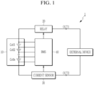
- FIG. 1 illustrates a battery system according to an embodiment.
- the battery system 1 includes a battery 10, a relay 20, a current sensor 30, and a battery management system (BMS) 40.
- BMS battery management system
- the battery 10 includes a plurality of battery cells Cell1 to Celln that are electrically connected.
- the battery cells may be rechargeable batteries.
- a predetermined number of battery cells may be connected in series to constitute a battery module, and a predetermined number of battery modules may be connected in series and parallel to constitute the battery 10 to supply desired power.
- Each of the battery cells Cell1 to Celln is electrically connected to the BMS 40 through wires.
- the battery 10 includes the plurality of battery cells Cell1 to Celln connected in series, and is connected between two output terminals OUT1 and OUT2 of the battery system 1.
- the relay 20 is connected between a positive electrode of the battery 10 and the output terminal OUT1, and the current sensor 30 is connected between a negative electrode of the battery 10 and the output terminal OUT2.
- the constituent elements illustrated in FIG. 1 and a connection relationship between the constituent elements are examples, and the present invention is not limited thereto.
- the relay 20 controls electrical connection between the battery system 1 and an external device.
- the relay 20 When the relay 20 is turned on, the battery system 1 and the external device are electrically connected to perform charging or discharging, and when the relay 20 is turned off, the battery system 1 and the external device are electrically separated.
- the external device may serve as a charger in a charging mode in which the battery 10 is charged by supplying power, or a load in a discharge mode in which power stored in the battery 10 is discharged.
- the current sensor 30 is connected in series to a current path between the battery 10 and the external device.
- the current sensor 30 may measure a current flowing through the battery 10, i.e., a charging current and a discharging current, and may transmit a measurement result to the BMS 40.
- the BMS 40 may collect and analyze various information related to the battery cells Cell1 to Celln to control charging and discharging of the battery cells, cell balancing, a protection operation, and the like, and may control an operation of the relay 20.
- the BMS 40 may control charging of the battery 10 in a normal mode (NORMAL MODE) or an eco-friendly mode (ECO MODE) depending on user selection.
- NVMAL MODE normal mode
- ECO MODE eco-friendly mode
- the battery 10 uses a maximum usable battery capacity (hereinafter, a first battery capacity) within a designed range, and uses a charging method selected by a user among a slow charging method or a rapid charging method to charge the battery 10.
- a first battery capacity a maximum usable battery capacity
- the normal mode is a method of using and managing the battery 10 in an initially designed state.
- the battery 10 uses a narrower battery capacity (hereinafter, second battery capacity) than the maximum usable battery capacity in a designed range, and charges the battery 10 by a slow charging method.
- the eco-friendly mode (ECO MODE) is a battery management method for extending the cycle-life of the battery 10, and may be set by user selection. That is, the eco-friendly mode (ECO MODE) is a battery management method that slows down an aging rate of the battery 10 by limiting excessive use of the battery capacity and the rapid charging method.
- a state of charge (SOC) is an amount of energy that is currently stored in the battery 10, and a unit thereof is percent (%).
- SOC state of charge
- the state of charge SOC is 100 %.
- the state of charge (SOC) is 0 %.
- the state of charge (SOC) decreases to 100 %, 80 %, 60 %, etc. as time elapses.
- the state of charge (SOC) cannot be directly measured, and the BMS 40 may estimate the state of charge (SOC) by an indirect method such as a conventionally known current integration method or a voltage measurement method.
- the BMS 40 may estimate the state of charge (SOC) in a predetermined period or in real time.
- the battery capacity is a total amount of energy that the battery 10 can store, and the unit is ampere-hours (Ah) and represents how long a constant current can flow. For example, when a current of 1 A flows for 1 hour, the battery capacity is 1 AH, and when it flows for 2 hours, the battery capacity is 2 AH.
- the first battery capacity may include a battery capacity having a range between a first lower limit SOC and a first upper limit SOC provided in a design and production process of the battery 10.
- the first battery capacity may include a battery capacity defined as 0 % to 100 %, or substantially in a range of 2 % to 96 % in consideration of a design margin, resistance, calculation error, and the like.
- the second battery capacity may include a battery capacity in a narrower region than the first battery capacity in order to slow the aging rate of the battery 10.
- the second battery capacity may include a battery capacity having a range between a second lower limit SOC that is a predetermined magnitude that is greater than the first lower limit SOC and a second upper limit SOC that is a predetermined magnitude that is smaller than the first upper limit SOC.
- the second battery capacity may include a battery capacity defined as a range between 30 % and 80 %.
- the BMS 40 In the normal mode (NORMAL MODE), the BMS 40 enters a charging mode for supplying power to the battery 10 when the state of charge (SOC) reaches the first lower limit SOC (e.g., 2 %). When a real-time state of charge (SOC) reaches the first upper limit SOC (e.g., 96 %) by supplying power to battery 10, the BMS 40 may end the charging mode.
- the BMS 40 enters a charging mode for supplying power to the battery 10 when the state of charge (SOC) reaches the second lower limit SOC (e.g., 30 %). When a real-time state of charge (SOC) reaches the second upper limit SOC (e.g., 80 %) by supplying power to battery 10, the BMS 40 may end the charging mode.
- Slow charging and rapid charging are battery charging methods that are divided depending on the charging speed.
- the slow charging is a slow charging method for completing the charging of the battery 10 after exceeding a predetermined reference time.
- the rapid charging is a fast charging method for completing the charging of the battery 10 within a predetermined reference time.
- aging of the battery 10 may be accelerated.
- the aging of the battery 10 may be accelerated compared to when the battery 10 is charged by the slow charging method.
- a state of health (SOH) is a performance index that is obtained by comparing an ideal battery state with a current battery state. For example, although the battery 10 initially had a battery capacity of 1000 mAh, the battery capacity may decrease to 850 mAh after use for a predetermined period of time. Then, the battery state of health (SOH) becomes 85 %.
- states of charge (SOC) at the time of full charge and full discharge of the battery 10 are 100 % and 0 %, respectively.
- the states of charge (SOC) at the time of full charge and full discharge of the battery 10 are 100 % and 0 %, respectively. That is, the state of charge (SOC) is 100 % when the energy that can be filled in the battery 10 is fully filled, and is 0 % when the energy is exhausted, regardless of the state of health (SOH) of the battery.
- the battery 10 with a battery state of health (SOH) of 100 % can supply a total of 1000 mAh of energy after being fully charged, whereas the battery 10 with a battery state of health (SOH) of 85 % can only supply a total of 850 mAh energy after being fully charged.
- the battery capacity decreases in response to the battery state of health (SOH).
- SOH battery state of health
- a time when the battery state of health (SOH) is decreased to a predetermined reference value, e.g., 80 %, may be regarded as a battery replacement time.
- a predetermined reference value e.g. 80 %
- the battery capacity is rapidly deteriorated and the battery 10 cannot perform its original role.
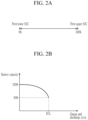
- FIG. 2A and 2B illustrate views for describing a normal mode according to an embodiment
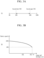
- FIG. 3A and 3B illustrate views for describing an eco-friendly mode according to an embodiment.
- a first key Key_1 for executing the eco-friendly mode may be provided on a user interface (not illustrated).
- the BMS 40 may control the charging of the battery 10 in the eco-friendly mode (ECO MODE) depending on user selection (ON) or the normal mode (NORMAL MODE) depending on non-selection (OFF).
- the BMS 40 may receive a first key-on signal for selecting the first key Key_1 or a first key-off signal for not selecting the first key Key_1 from an electronic control unit (ECU).
- the first key Key_1 for executing the eco-friendly mode (ECO MODE) and a second key Key_2 for executing the normal mode (NORMAL MODE), which can be manipulated by the user may be provided in a user interface.
- the BMS 40 may control the charging of the battery 10 in the eco-friendly mode (ECO MODE).
- the BMS 40 may control the charging of the battery 10 in the normal mode (NORMAL MODE).
- the BMS 40 may receive the first key-on signal for selecting the first key Key_1 or a second key-on signal for selecting the second key Key_2 of the normal mode (NORMAL MODE) from the electronic control unit (ECU).
- the first battery capacity is set to a usable battery capacity (hereinafter, the available battery capacity), and rapid charging is enabled. Accordingly, the BMS 40 may control the charging of the battery 10 in a first battery capacity range by the fast charging or slow charging method depending on the user selection.
- an end of life (EOL) of the battery 10 may be determined as a time when the available battery capacity reaches a predetermined reference value (80 %) compared to an initial state (100 %). That is, when the battery state of health (SOH) reaches 80 %, the battery 10 should be discarded.
- the end of life (EOL) may be determined depending on a number of charge and discharge cycles. For example, a lithium-ion battery is determined to have reached the end of life (EOL) when 300 to 500 charge and discharge cycles have elapsed.
- the second battery capacity is set to an available battery capacity, and the fast charging method is disabled. Accordingly, the BMS 40 may control the charging of the battery 10 in a second battery capacity range by the slow charging method.
- the second battery capacity may be set to a battery capacity in a range that is smaller than the first battery capacity.
- an end of life (EOL+ ⁇ ) of the battery 10 may be extended for a predetermined period of time ⁇ than when the battery 10 is used and managed in the normal mode (NORMAL MODE).
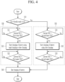
- FIG. 4 illustrates a flowchart describing a method of extending cycle-life of a battery by charging the battery in a normal mode or an eco-friendly mode depending on user selection according to an embodiment.
- the BMS 40 determines whether the eco-friendly mode (ECO MODE) is in an on state by user selection (S10).
- ECO MODE eco-friendly mode
- a first key Key_1 for executing the eco-friendly mode may be provided on a user interface (not illustrated).
- the BMS 40 may determine the eco-friendly mode (ECO MODE), while when the user does not select the first key Key_1, the BMS 40 may determine the normal mode (NORMAL MODE). That is, when the user does not take any action, the BMS 40 may determine the normal mode (NORMAL MODE).
- the BMS 40 may receive a first key-on signal for indicating selection of the first key Key_1 or a first key-off signal for indicating non-selection of the first key Key_1 from an electronic control unit (ECU).
- ECU electronice control unit
- the first key Key_1 for executing the eco-friendly mode (ECO MODE) and a second key Key_2 for executing the normal mode (NORMAL MODE) may be provided in a user interface.
- the BMS 40 may determine the eco-friendly mode (ECO MODE), while when the user does not select the second key Key_2, the BMS 40 may determine the normal mode (NORMAL MODE).
- the BMS 40 may receive the first key-on signal for selecting the first key Key_1 or a second key-on signal for selecting the second key Key_2 of the normal mode (NORMAL MODE) from the electronic control unit (ECU).
- the BMS 40 controls the charging of the battery 10 in the normal mode (NORMAL MODE) (S20).
- step S20 first, the BMS 40 diagnoses whether a current state of charge (SOC) reaches a first lower limit SOC of the first battery capacity (S21).
- SOC current state of charge
- the normal mode is a method of managing the battery 10 as designed.
- the normal mode uses the first battery capacity, which is a maximum battery capacity that is usable in the designed range.
- the first battery capacity may be a battery capacity having a range between a first lower limit SOC and a first upper limit SOC provided in a design and production process of the battery 10. Assuming an ideal state, the first battery capacity may include a battery capacity defined in a range between 0 % and 100 %.
- the BMS 40 may calculate the current state of charge (SOC) by estimating the state of charge (SOC) in a predetermined period or in real time.
- step S20 when the state of charge SOC reaches the first lower limit SOC (S21, Yes), the BMS 40 enters a charging mode for supplying power to the battery 10 (S22).
- the BMS 40 may control the charging of the battery 10 in a first battery capacity range by the fast charging or slow charging method depending on the user selection. For example, when the user selects the rapid charging, the BMS 40 may control power to be supplied to the battery 10 through rapid charging.
- the BMS 40 may request the user to select the charging method through the electronic control unit (ECU).
- the electronic control unit (ECU) may control a message requesting selection of one of the fast charging and the slow charging method to be displayed on a user interface.
- step S20 the BMS 40 diagnoses whether a current state of charge (SOC) reaches a first upper limit SOC of the first battery capacity (S23).
- SOC current state of charge
- the battery 10 receives power from an external device, and the state of charge (SOC) increases as time elapses.
- SOC state of charge
- the state of charge (SOC) may gradually increase to 10 %, 30 %, or 50 % as time elapses.
- the BMS 40 controls the charging of the battery 10 in the eco-friendly mode (ECO MODE) (S30).
- step S30 first, the BMS 40 diagnoses whether the state of charge (SOC) reaches a second lower limit SOC of the second battery capacity (S31).
- the eco-friendly mode is a battery management method for extending the cycle-life of the battery 10, and may be set by user selection.
- the second battery capacity which is a battery capacity in a narrower region than that of the first battery capacity, is used.
- the second battery capacity may include a battery capacity having a range between a second lower limit SOC that is a predetermined magnitude that is greater than the first lower limit SOC and a second upper limit SOC that is a predetermined magnitude that is smaller than the first upper limit SOC.
- the second battery capacity may include a battery capacity defined as a range between 30 % and 80 %.
- the first lower limit SOC of the first battery capacity is smaller than the second lower limit SOC of the second battery capacity, and the first upper limit SOC is greater than the second upper limit SOC of the second battery capacity.
- step S30 when the state of charge SOC reaches the second lower limit SOC (S31, Yes), the BMS 40 enters a charging mode for supplying power to the battery 10 (S32).
- the BMS 40 may control the charging of the battery 10 in the second battery capacity range by the slow charging method.
- SOC state of charge
- the BMS 40 may control the battery 10 to be charged without further discharging.
- step S30 the BMS 40 diagnoses whether the state of charge (SOC) reaches the second upper limit SOC of the second battery capacity (S33).
- the BMS 40 may end the charging mode S40.
- the BMS 40 may end charging of the battery 10(S40). For example, the BMS 40 may end the charging of the battery 10 when the state of charge (SOC) reaches 100 %.
- SOC state of charge
- the BMS 40 may end charging of the battery 10(S40). For example, in the case where charging is started when the state of charge (SOC) is 30 %, the state of charge (SOC) may gradually increase to 30 % or 70 % as time elapses. When the state of charge (SOC) reaches the second upper limit SOC, e.g., 80%, the BMS 40 may end the charging mode such that the battery 10 is no longer charged.
- SOC state of charge
- the second upper limit SOC e.g., 80%
Landscapes
- Engineering & Computer Science (AREA)
- Power Engineering (AREA)
- Transportation (AREA)
- Mechanical Engineering (AREA)
- Sustainable Energy (AREA)
- Sustainable Development (AREA)
- Life Sciences & Earth Sciences (AREA)
- Electrochemistry (AREA)
- General Chemical & Material Sciences (AREA)
- Chemical Kinetics & Catalysis (AREA)
- Chemical & Material Sciences (AREA)
- Manufacturing & Machinery (AREA)
- Microelectronics & Electronic Packaging (AREA)
- Charge And Discharge Circuits For Batteries Or The Like (AREA)
- Secondary Cells (AREA)
- Electric Propulsion And Braking For Vehicles (AREA)
Claims (7)
- Batteriesystem, umfassend:eine Batterie; undein Batterieverwaltungssystem, BMS, das konfiguriert ist zum Steuern von Laden der Batterie abhängig von einem normalen Modus, in dem die Batterie mit einer ersten Batteriekapazität zwischen einem ersten unteren Ladezustandsgrenzwert, SOC, und einem ersten oberen SOC-Grenzwert geladen wird, oder einem umweltfreundlichen Modus, ECO-Modus, in dem die Batterie mit einer zweiten Batteriekapazität zwischen einem zweiten unteren SOC-Grenzwert und einem zweiten oberen SOC-Grenzwert geladen wird,wobei der erste untere SOC-Grenzwert kleiner ist als der zweite untere SOC-Grenzwert, undder erste obere SOC-Grenzwert größer ist als der zweite obere SOC-Grenzwert,wobei das BMS so konfiguriert ist, dass es in einem eingeschalteten Zustand des normalen Modus einen aktuellen SOC berechnet durch Schätzen eines SOC der Batterie in jeder vorbestimmten Zeitspanne, und Laden der Batterie startet, wenn der aktuelle SOC den ersten unteren SOC-Grenzwert erreicht, und Laden der Batterie beendet, wenn der aktuelle SOC den ersten oberen SOC-Grenzwert erreicht,wobei das BMS so konfiguriert ist, dass es in einem eingeschalteten Zustand des normalen Modus Laden der Batterie durch Verwenden eines Schnellladeverfahrens des Ladens der Batterie steuert, um Laden der Batterie von dem Zeitpunkt, an dem der aktuelle SOC den ersten unteren SOC-Grenzwert erreicht, bis zu dem Zeitpunkt, an dem der aktuelle SOC den ersten oberen SOC-Grenzwert erreicht, innerhalb einer vorbestimmten Referenzzeit abzuschließen, oder ein langsames Ladeverfahren des Ladens der Batterie durchführt, um Laden der Batterie von dem Zeitpunkt, an dem der aktuelle SOC den ersten unteren SOC-Grenzwert erreicht, bis zu dem Zeitpunkt, an dem der aktuelle SOC den ersten oberen SOC-Grenzwert erreicht, nach Überschreiten der vorbestimmten Referenzzeit abzuschließen,wobei das BMS so konfiguriert ist, dass es in einem eingeschalteten Zustand des normalen Modus Laden der Batterie durch das Schnellladeverfahren oder das langsame Ladeverfahren abhängig von einer Benutzerauswahl steuert.
- Batteriesystem nach Anspruch 1, wobei das BMS so konfiguriert ist, dass eseinen aktuellen SOC durch Schätzen eines SOC der Batterie in jeder vorbestimmten Zeitspanne berechnet, und in einem eingeschalteten Zustand des umweltfreundlichen ModusLaden der Batterie startet, wenn der aktuelle SOC den zweiten unteren SOC-Grenzwert erreicht, und Laden der Batterie beendet, wenn der aktuelle SOC den zweiten oberen SOC-Grenzwert erreicht.
- Batteriesystem nach Anspruch 2, wobei das BMS so konfiguriert ist, dass esin einem eingeschalteten Zustand des umweltfreundlichen ModusLaden der Batterie durch Verwenden des langsamen Ladeverfahrens zum Laden der Batterie steuert, um Laden der Batterie von dem Zeitpunkt, an dem der aktuelle SOC den zweiten unteren SOC-Grenzwert erreicht, bis zu dem Zeitpunkt, an dem der aktuelle SOC den zweiten oberen SOC-Grenzwert erreicht, nach Überschreiten der vorbestimmten Referenzzeit abzuschließen.
- Batteriesystem nach Anspruch 1, wobei das BMS so konfiguriert ist, dass esbestimmt, dass der umweltfreundliche Modus in einem eingeschalteten Zustand ist, wenn es ein Taste-ein-Signal des ECO-Modus zum Anzeigen der Auswahl des umweltfreundlichen Modus durch einen Benutzer empfängt, undbestimmt, dass der normale Modus in einem eingeschalteten Zustand ist, wenn es ein Taste-aus-Signal des umweltfreundlichen Modus zum Anzeigen der Nicht-Auswahl des umweltfreundlichen Modus durch den Benutzer empfängt.
- Batterieverwaltungsverfahren für ein Batterieverwaltungssystem, BMS, das konfiguriert ist zum Verwalten einer Batterie durch Steuern von Laden der Batterie abhängig von einem normalen Modus, in dem die Batterie mit einer ersten Batteriekapazität zwischen einem ersten unteren Ladezustandsgrenzwert, SOC, und einem ersten oberen SOC-Grenzwert geladen wird, oder einem umweltfreundlichen Modus, in dem die Batterie mit einer zweiten Batteriekapazität zwischen einem zweiten unteren SOC-Grenzwert und einem zweiten oberen SOC-Grenzwert geladen wird, wobei das Verfahren Folgendes umfasst:Bestimmen, ob der umweltfreundliche Modus, ECO-Modus, in einem eingeschalteten Zustand ist;Starten und Steuern des Ladens der Batterie, wenn ein aktueller SOC, der in jeder vorbestimmten Zeitspanne geschätzt wird, den ersten unteren SOC-Grenzwert oder den zweiten unteren SOC-Grenzwert erreicht, abhängig von einem Bestimmungsergebnis davon; undBeenden des Ladens der Batterie, wenn der aktuelle SOC den ersten oberen SOC-Grenzwert oder den zweiten oberen SOC-Grenzwert erreicht,wobei der erste untere SOC-Grenzwert kleiner ist als der zweite untere SOC-Grenzwert, und der erste obere SOC-Grenzwert größer ist als der zweite obere SOC-Grenzwert,wobei Starten und Steuern des Ladens der Batterie Folgendes einschließt:Diagnostizieren als Ergebnis der Bestimmung, ob der aktuelle SOC den ersten unteren SOC-Grenzwert erreicht oder nicht, wenn der normale Modus in einem eingeschalteten Zustand ist;Starten des Ladens der Batterie durch Verwenden eines Schnellladeverfahrens des Ladens der Batterie, um Laden der Batterie von dem Zeitpunkt, an dem der aktuelle SOC den ersten unteren SOC-Grenzwert erreicht, bis zu dem Zeitpunkt, an dem der aktuelle SOC den ersten oberen SOC-Grenzwert erreicht, innerhalb einer vorbestimmten Referenzzeit abzuschließen, oder eines langsamen Ladeverfahrens des Ladens der Batterie, um Laden der Batterie von dem Zeitpunkt, an dem der aktuelle SOC den ersten unteren SOC-Grenzwert erreicht, bis zu dem Zeitpunkt, an dem der aktuelle SOC den ersten oberen SOC-Grenzwert erreicht, nach Überschreiten der vorbestimmten Referenzzeit abzuschließen, wenn er als Ergebnis der Diagnose erreicht wird; undDiagnostizieren, ob der aktuelle SOC den ersten oberen SOC-Grenzwert erreicht,wobei das Starten des Ladens der Batterie Folgendes einschließt:
Steuern des Ladens der Batterie durch das Schnellladeverfahren oder das langsame Ladeverfahren abhängig von einer Benutzerauswahl. - Batterieverwaltungsverfahren nach Anspruch 5, wobei
Starten und Steuern des Ladens der Batterie Folgendes einschließt:Diagnostizieren als Ergebnis der Bestimmung, ob der aktuelle SOC den zweiten unteren SOC-Grenzwert erreicht oder nicht, wenn der umweltfreundliche Modus in einem eingeschalteten Zustand ist;Starten des Ladens der Batterie durch Verwenden des langsamen Ladeverfahrens zum Laden der Batterie, um Laden der Batterie von dem Zeitpunkt, an dem der aktuelle SOC den zweiten unteren SOC-Grenzwert erreicht, bis zu dem Zeitpunkt, an dem der aktuelle SOC den zweiten oberen SOC-Grenzwert erreicht, nach Überschreiten der vorbestimmten Referenzzeit abzuschließen, wenn er als Ergebnis der Diagnose erreicht wird; undDiagnostizieren, ob der aktuelle SOC den zweiten oberen SOC-Grenzwert erreicht. - Batterieverwaltungsverfahren nach Anspruch 5, wobei das Bestimmen, ob der umweltfreundliche Modus, ECO-Modus, in einem eingeschalteten Zustand ist, Folgendes einschließt:
Bestimmen, dass der umweltfreundliche Modus in einem eingeschalteten Zustand ist, wenn ein Taste-ein-Signal des ECO-Modus empfangen wird zum Anzeigen einer Auswahl des umweltfreundlichen Modus durch einen Benutzer, und Bestimmen, dass der normale Modus in einem eingeschalteten Zustand ist, wenn ein Taste-aus-Signal des umweltfreundlichen Modus empfangen wird zum Anzeigen einer Nicht-Auswahl des umweltfreundlichen Modus durch den Benutzer.
Applications Claiming Priority (2)
| Application Number | Priority Date | Filing Date | Title |
|---|---|---|---|
| KR1020200087773A KR20220009273A (ko) | 2020-07-15 | 2020-07-15 | 배터리 관리 방법 및 그 방법을 제공하는 배터리 시스템 |
| PCT/KR2021/008740 WO2022014953A1 (ko) | 2020-07-15 | 2021-07-08 | 배터리 관리 방법 및 그 방법을 제공하는 배터리 시스템 |
Publications (3)
| Publication Number | Publication Date |
|---|---|
| EP4032746A1 EP4032746A1 (de) | 2022-07-27 |
| EP4032746A4 EP4032746A4 (de) | 2023-01-18 |
| EP4032746B1 true EP4032746B1 (de) | 2024-09-18 |
Family
ID=79555532
Family Applications (1)
| Application Number | Title | Priority Date | Filing Date |
|---|---|---|---|
| EP21842305.1A Active EP4032746B1 (de) | 2020-07-15 | 2021-07-08 | Verfahren zur batterieverwaltung und batteriesystem damit |
Country Status (8)
| Country | Link |
|---|---|
| US (1) | US12351058B2 (de) |
| EP (1) | EP4032746B1 (de) |
| JP (1) | JP7509360B2 (de) |
| KR (1) | KR20220009273A (de) |
| CN (1) | CN114616125B (de) |
| ES (1) | ES2994645T3 (de) |
| HU (1) | HUE068438T2 (de) |
| WO (1) | WO2022014953A1 (de) |
Families Citing this family (4)
| Publication number | Priority date | Publication date | Assignee | Title |
|---|---|---|---|---|
| CN114598015B (zh) * | 2022-03-08 | 2025-05-16 | 兰州理工大学 | 用于mmc退役动力电池储能系统的子模块控制方法 |
| EP4680486A1 (de) * | 2023-03-16 | 2026-01-21 | ABB E-mobility B.V. | Systeme und verfahren zur steuerung einer vergebührungssitzung |
| CN116872792B (zh) * | 2023-08-22 | 2024-04-02 | 杭州鸿途智慧能源技术有限公司 | 一种基于快速更换补能动力电池混合动力控制系统 |
| CN119408458A (zh) * | 2024-11-21 | 2025-02-11 | 东风汽车有限公司东风日产乘用车公司 | 动力电池容量修正方法、存储介质和电子设备 |
Family Cites Families (30)
| Publication number | Priority date | Publication date | Assignee | Title |
|---|---|---|---|---|
| JP2000134719A (ja) * | 1998-10-29 | 2000-05-12 | Isuzu Motors Ltd | パラレル・ハイブリッド電気自動車のバッテリ充電制御装置 |
| JP2005312224A (ja) | 2004-04-23 | 2005-11-04 | Toyota Industries Corp | バッテリ充電装置 |
| JP4241837B2 (ja) | 2007-01-15 | 2009-03-18 | トヨタ自動車株式会社 | 車両およびその制御方法 |
| CN101468610B (zh) * | 2007-12-28 | 2011-03-30 | 比亚迪股份有限公司 | 一种用于混合动力车辆的充电控制装置及其方法 |
| JP4805328B2 (ja) | 2008-10-31 | 2011-11-02 | 本田技研工業株式会社 | 電動車両 |
| JP2010201987A (ja) * | 2009-02-27 | 2010-09-16 | Mitsubishi Heavy Ind Ltd | ハイブリッド車両の駆動制御装置 |
| EP2502774B1 (de) | 2009-11-17 | 2015-02-25 | Toyota Jidosha Kabushiki Kaisha | Fahrzeug und steuerungsverfahren für das fahrzeug |
| JP5310855B2 (ja) | 2009-12-01 | 2013-10-09 | 株式会社村田製作所 | アンテナマッチング装置、アンテナ装置及び移動体通信端末 |
| US8629657B2 (en) | 2009-12-31 | 2014-01-14 | Tesla Motors, Inc. | State of charge range |
| JP5732766B2 (ja) | 2010-07-23 | 2015-06-10 | トヨタ自動車株式会社 | 車両の制御装置および制御方法 |
| US8937452B2 (en) | 2011-02-04 | 2015-01-20 | GM Global Technology Operations LLC | Method of controlling a state-of-charge (SOC) of a vehicle battery |
| JP5877360B2 (ja) | 2011-05-26 | 2016-03-08 | パナソニックIpマネジメント株式会社 | 蓄電池制御システム |
| KR101825617B1 (ko) * | 2011-12-27 | 2018-02-06 | 주식회사 엘지화학 | 배터리 사용 영역 가변 장치 및 방법 |
| KR101512879B1 (ko) | 2012-04-25 | 2015-04-16 | 엘에스산전 주식회사 | 전기 자동차의 충전 시스템 |
| CN102856601A (zh) | 2012-08-22 | 2013-01-02 | 杭州杰能动力有限公司 | 汽车充电时调整实时电池容量的方法、系统及电动汽车 |
| JP2014143815A (ja) | 2013-01-23 | 2014-08-07 | Konica Minolta Inc | 電子機器および画像形成装置 |
| JP2014147197A (ja) | 2013-01-29 | 2014-08-14 | Hitachi Automotive Systems Ltd | バッテリ制御装置 |
| KR101488586B1 (ko) | 2013-03-04 | 2015-02-02 | 주식회사 엘지씨엔에스 | 전기차 동적 충전 방법 및 시스템 |
| JP5683627B2 (ja) | 2013-03-22 | 2015-03-11 | トヨタ自動車株式会社 | 電源制御装置 |
| JP5825288B2 (ja) * | 2013-04-08 | 2015-12-02 | トヨタ自動車株式会社 | ハイブリッド車両 |
| KR101592742B1 (ko) | 2014-07-28 | 2016-02-18 | 현대자동차주식회사 | 친환경 자동차의 완속 충전 제어 방법 |
| KR101622194B1 (ko) | 2014-10-31 | 2016-05-18 | 영화테크(주) | 배터리 보호 기능을 갖는 전기 차량용 배터리 충전 장치 |
| US9969293B2 (en) * | 2015-03-30 | 2018-05-15 | Ford Global Technologies, Llc | Battery thermal conditioning to extend battery useful life in electrified vehicles |
| JP6304165B2 (ja) | 2015-07-31 | 2018-04-04 | トヨタ自動車株式会社 | ハイブリッド車両の制御装置 |
| WO2017042973A1 (ja) | 2015-09-11 | 2017-03-16 | 株式会社東芝 | 蓄電池システム、方法及びプログラム |
| CN105818705B (zh) | 2016-03-25 | 2018-11-06 | 郑州宇通客车股份有限公司 | 电动汽车充电控制方法和电动汽车充电控制装置 |
| KR101826617B1 (ko) | 2016-05-26 | 2018-02-08 | 성창산업 주식회사 | 비닐하우스용 양액재배 장치 |
| JP2019030161A (ja) | 2017-08-01 | 2019-02-21 | 大阪瓦斯株式会社 | 分散型電源システム |
| WO2019116586A1 (ja) | 2017-12-15 | 2019-06-20 | 日産自動車株式会社 | ハイブリッド車両の制御方法、及び、制御装置 |
| WO2019120570A1 (en) | 2017-12-22 | 2019-06-27 | Volvo Truck Corporation | A method of controlling a state of charge operation range of a vehicle electrical system |
-
2020
- 2020-07-15 KR KR1020200087773A patent/KR20220009273A/ko active Pending
-
2021
- 2021-07-08 CN CN202180006177.0A patent/CN114616125B/zh active Active
- 2021-07-08 ES ES21842305T patent/ES2994645T3/es active Active
- 2021-07-08 HU HUE21842305A patent/HUE068438T2/hu unknown
- 2021-07-08 JP JP2022520021A patent/JP7509360B2/ja active Active
- 2021-07-08 US US17/769,866 patent/US12351058B2/en active Active
- 2021-07-08 WO PCT/KR2021/008740 patent/WO2022014953A1/ko not_active Ceased
- 2021-07-08 EP EP21842305.1A patent/EP4032746B1/de active Active
Also Published As
| Publication number | Publication date |
|---|---|
| EP4032746A1 (de) | 2022-07-27 |
| JP2022551065A (ja) | 2022-12-07 |
| CN114616125A (zh) | 2022-06-10 |
| ES2994645T3 (en) | 2025-01-28 |
| US20220388417A1 (en) | 2022-12-08 |
| CN114616125B (zh) | 2024-05-14 |
| JP7509360B2 (ja) | 2024-07-02 |
| WO2022014953A1 (ko) | 2022-01-20 |
| US12351058B2 (en) | 2025-07-08 |
| HUE068438T2 (hu) | 2024-12-28 |
| EP4032746A4 (de) | 2023-01-18 |
| KR20220009273A (ko) | 2022-01-24 |
Similar Documents
| Publication | Publication Date | Title |
|---|---|---|
| EP4032746B1 (de) | Verfahren zur batterieverwaltung und batteriesystem damit | |
| JP3964635B2 (ja) | メモリー効果の検出方法およびその解消方法 | |
| US9358899B2 (en) | Method for revitalizing and increasing lithium ion battery capacity | |
| KR101245788B1 (ko) | 배터리의 작동점 제어 방법 및 장치 | |
| JP5341823B2 (ja) | リチウムイオン二次電池の劣化判定システムおよび劣化判定方法 | |
| CN101536285B (zh) | 蓄电元件的异常检测装置以及方法 | |
| JP4670831B2 (ja) | 電気自動車用バッテリ容量検知方法及び装置並びに電気自動車のメンテナンス方法 | |
| US8749201B2 (en) | Battery pack capacity learn algorithm | |
| JP5356439B2 (ja) | 充電制御装置および充電制御方法 | |
| US10574063B2 (en) | Method and system for balancing a battery pack | |
| US8674659B2 (en) | Charge control device and vehicle equipped with the same | |
| EP2993758A1 (de) | Ladungssteuerungsvorrichtung und ladungssteuerungsverfahren | |
| JP2002369391A (ja) | 二次電池の残存容量制御方法および装置 | |
| JP2010098866A (ja) | 不均衡判定回路、不均衡低減回路、電池電源装置、及び不均衡判定方法 | |
| JP2003079059A (ja) | 車載組電池制御装置 | |
| KR101567557B1 (ko) | 이차 전지 셀의 전압 벨런싱 장치 및 방법 | |
| JP2004031014A (ja) | 並列接続電池を含む組電池の最大充放電電力演算方法および装置 | |
| JP2026015351A (ja) | 蓄電装置、蓄電システム、内部抵抗推定方法及びコンピュータプログラム | |
| JP2013031248A (ja) | バッテリ装置のヒステリシス低減システム | |
| WO2013105139A1 (ja) | 二次電池の制御装置および制御方法 | |
| KR20250119192A (ko) | 배터리 관리 장치 및 방법 | |
| KR20250062887A (ko) | 하이브리드 배터리 시스템 | |
| JP5257173B2 (ja) | 車載電源装置 | |
| CN116316935A (zh) | 电源管理方法及车辆辅助电源 |
Legal Events
| Date | Code | Title | Description |
|---|---|---|---|
| STAA | Information on the status of an ep patent application or granted ep patent |
Free format text: STATUS: THE INTERNATIONAL PUBLICATION HAS BEEN MADE |
|
| PUAI | Public reference made under article 153(3) epc to a published international application that has entered the european phase |
Free format text: ORIGINAL CODE: 0009012 |
|
| STAA | Information on the status of an ep patent application or granted ep patent |
Free format text: STATUS: REQUEST FOR EXAMINATION WAS MADE |
|
| 17P | Request for examination filed |
Effective date: 20220420 |
|
| AK | Designated contracting states |
Kind code of ref document: A1 Designated state(s): AL AT BE BG CH CY CZ DE DK EE ES FI FR GB GR HR HU IE IS IT LI LT LU LV MC MK MT NL NO PL PT RO RS SE SI SK SM TR |
|
| A4 | Supplementary search report drawn up and despatched |
Effective date: 20221220 |
|
| RIC1 | Information provided on ipc code assigned before grant |
Ipc: B60L 58/16 20190101ALI20221214BHEP Ipc: H01M 10/42 20060101ALI20221214BHEP Ipc: H02J 7/00 20060101ALI20221214BHEP Ipc: H01M 10/44 20060101ALI20221214BHEP Ipc: B60L 53/10 20190101ALI20221214BHEP Ipc: B60L 58/13 20190101AFI20221214BHEP |
|
| DAV | Request for validation of the european patent (deleted) | ||
| DAX | Request for extension of the european patent (deleted) | ||
| RIC1 | Information provided on ipc code assigned before grant |
Ipc: B60L 58/16 20190101ALI20240322BHEP Ipc: H01M 10/42 20060101ALI20240322BHEP Ipc: H02J 7/00 20060101ALI20240322BHEP Ipc: H01M 10/44 20060101ALI20240322BHEP Ipc: B60L 53/10 20190101ALI20240322BHEP Ipc: B60L 58/13 20190101AFI20240322BHEP |
|
| GRAP | Despatch of communication of intention to grant a patent |
Free format text: ORIGINAL CODE: EPIDOSNIGR1 |
|
| STAA | Information on the status of an ep patent application or granted ep patent |
Free format text: STATUS: GRANT OF PATENT IS INTENDED |
|
| INTG | Intention to grant announced |
Effective date: 20240503 |
|
| GRAS | Grant fee paid |
Free format text: ORIGINAL CODE: EPIDOSNIGR3 |
|
| GRAA | (expected) grant |
Free format text: ORIGINAL CODE: 0009210 |
|
| STAA | Information on the status of an ep patent application or granted ep patent |
Free format text: STATUS: THE PATENT HAS BEEN GRANTED |
|
| AK | Designated contracting states |
Kind code of ref document: B1 Designated state(s): AL AT BE BG CH CY CZ DE DK EE ES FI FR GB GR HR HU IE IS IT LI LT LU LV MC MK MT NL NO PL PT RO RS SE SI SK SM TR |
|
| P01 | Opt-out of the competence of the unified patent court (upc) registered |
Free format text: CASE NUMBER: APP_46768/2024 Effective date: 20240813 |
|
| REG | Reference to a national code |
Ref country code: GB Ref legal event code: FG4D |
|
| REG | Reference to a national code |
Ref country code: CH Ref legal event code: EP |
|
| REG | Reference to a national code |
Ref country code: IE Ref legal event code: FG4D |
|
| REG | Reference to a national code |
Ref country code: DE Ref legal event code: R096 Ref document number: 602021019104 Country of ref document: DE |
|
| REG | Reference to a national code |
Ref country code: HU Ref legal event code: AG4A Ref document number: E068438 Country of ref document: HU |
|
| REG | Reference to a national code |
Ref country code: LT Ref legal event code: MG9D |
|
| PG25 | Lapsed in a contracting state [announced via postgrant information from national office to epo] |
Ref country code: NO Free format text: LAPSE BECAUSE OF FAILURE TO SUBMIT A TRANSLATION OF THE DESCRIPTION OR TO PAY THE FEE WITHIN THE PRESCRIBED TIME-LIMIT Effective date: 20241218 |
|
| PG25 | Lapsed in a contracting state [announced via postgrant information from national office to epo] |
Ref country code: GR Free format text: LAPSE BECAUSE OF FAILURE TO SUBMIT A TRANSLATION OF THE DESCRIPTION OR TO PAY THE FEE WITHIN THE PRESCRIBED TIME-LIMIT Effective date: 20241219 Ref country code: FI Free format text: LAPSE BECAUSE OF FAILURE TO SUBMIT A TRANSLATION OF THE DESCRIPTION OR TO PAY THE FEE WITHIN THE PRESCRIBED TIME-LIMIT Effective date: 20240918 |
|
| PG25 | Lapsed in a contracting state [announced via postgrant information from national office to epo] |
Ref country code: BG Free format text: LAPSE BECAUSE OF FAILURE TO SUBMIT A TRANSLATION OF THE DESCRIPTION OR TO PAY THE FEE WITHIN THE PRESCRIBED TIME-LIMIT Effective date: 20240918 |
|
| PG25 | Lapsed in a contracting state [announced via postgrant information from national office to epo] |
Ref country code: LV Free format text: LAPSE BECAUSE OF FAILURE TO SUBMIT A TRANSLATION OF THE DESCRIPTION OR TO PAY THE FEE WITHIN THE PRESCRIBED TIME-LIMIT Effective date: 20240918 |
|
| PG25 | Lapsed in a contracting state [announced via postgrant information from national office to epo] |
Ref country code: HR Free format text: LAPSE BECAUSE OF FAILURE TO SUBMIT A TRANSLATION OF THE DESCRIPTION OR TO PAY THE FEE WITHIN THE PRESCRIBED TIME-LIMIT Effective date: 20240918 |
|
| REG | Reference to a national code |
Ref country code: NL Ref legal event code: MP Effective date: 20240918 |
|
| PG25 | Lapsed in a contracting state [announced via postgrant information from national office to epo] |
Ref country code: RS Free format text: LAPSE BECAUSE OF FAILURE TO SUBMIT A TRANSLATION OF THE DESCRIPTION OR TO PAY THE FEE WITHIN THE PRESCRIBED TIME-LIMIT Effective date: 20241218 |
|
| REG | Reference to a national code |
Ref country code: ES Ref legal event code: FG2A Ref document number: 2994645 Country of ref document: ES Kind code of ref document: T3 Effective date: 20250128 |
|
| PG25 | Lapsed in a contracting state [announced via postgrant information from national office to epo] |
Ref country code: RS Free format text: LAPSE BECAUSE OF FAILURE TO SUBMIT A TRANSLATION OF THE DESCRIPTION OR TO PAY THE FEE WITHIN THE PRESCRIBED TIME-LIMIT Effective date: 20241218 Ref country code: NO Free format text: LAPSE BECAUSE OF FAILURE TO SUBMIT A TRANSLATION OF THE DESCRIPTION OR TO PAY THE FEE WITHIN THE PRESCRIBED TIME-LIMIT Effective date: 20241218 Ref country code: LV Free format text: LAPSE BECAUSE OF FAILURE TO SUBMIT A TRANSLATION OF THE DESCRIPTION OR TO PAY THE FEE WITHIN THE PRESCRIBED TIME-LIMIT Effective date: 20240918 Ref country code: HR Free format text: LAPSE BECAUSE OF FAILURE TO SUBMIT A TRANSLATION OF THE DESCRIPTION OR TO PAY THE FEE WITHIN THE PRESCRIBED TIME-LIMIT Effective date: 20240918 Ref country code: GR Free format text: LAPSE BECAUSE OF FAILURE TO SUBMIT A TRANSLATION OF THE DESCRIPTION OR TO PAY THE FEE WITHIN THE PRESCRIBED TIME-LIMIT Effective date: 20241219 Ref country code: FI Free format text: LAPSE BECAUSE OF FAILURE TO SUBMIT A TRANSLATION OF THE DESCRIPTION OR TO PAY THE FEE WITHIN THE PRESCRIBED TIME-LIMIT Effective date: 20240918 Ref country code: BG Free format text: LAPSE BECAUSE OF FAILURE TO SUBMIT A TRANSLATION OF THE DESCRIPTION OR TO PAY THE FEE WITHIN THE PRESCRIBED TIME-LIMIT Effective date: 20240918 |
|
| REG | Reference to a national code |
Ref country code: AT Ref legal event code: MK05 Ref document number: 1724425 Country of ref document: AT Kind code of ref document: T Effective date: 20240918 |
|
| PG25 | Lapsed in a contracting state [announced via postgrant information from national office to epo] |
Ref country code: NL Free format text: LAPSE BECAUSE OF FAILURE TO SUBMIT A TRANSLATION OF THE DESCRIPTION OR TO PAY THE FEE WITHIN THE PRESCRIBED TIME-LIMIT Effective date: 20240918 |
|
| PG25 | Lapsed in a contracting state [announced via postgrant information from national office to epo] |
Ref country code: PT Free format text: LAPSE BECAUSE OF FAILURE TO SUBMIT A TRANSLATION OF THE DESCRIPTION OR TO PAY THE FEE WITHIN THE PRESCRIBED TIME-LIMIT Effective date: 20250120 Ref country code: IS Free format text: LAPSE BECAUSE OF FAILURE TO SUBMIT A TRANSLATION OF THE DESCRIPTION OR TO PAY THE FEE WITHIN THE PRESCRIBED TIME-LIMIT Effective date: 20250118 |
|
| PG25 | Lapsed in a contracting state [announced via postgrant information from national office to epo] |
Ref country code: RO Free format text: LAPSE BECAUSE OF FAILURE TO SUBMIT A TRANSLATION OF THE DESCRIPTION OR TO PAY THE FEE WITHIN THE PRESCRIBED TIME-LIMIT Effective date: 20240918 Ref country code: SM Free format text: LAPSE BECAUSE OF FAILURE TO SUBMIT A TRANSLATION OF THE DESCRIPTION OR TO PAY THE FEE WITHIN THE PRESCRIBED TIME-LIMIT Effective date: 20240918 |
|
| PG25 | Lapsed in a contracting state [announced via postgrant information from national office to epo] |
Ref country code: EE Free format text: LAPSE BECAUSE OF FAILURE TO SUBMIT A TRANSLATION OF THE DESCRIPTION OR TO PAY THE FEE WITHIN THE PRESCRIBED TIME-LIMIT Effective date: 20240918 Ref country code: AT Free format text: LAPSE BECAUSE OF FAILURE TO SUBMIT A TRANSLATION OF THE DESCRIPTION OR TO PAY THE FEE WITHIN THE PRESCRIBED TIME-LIMIT Effective date: 20240918 |
|
| PG25 | Lapsed in a contracting state [announced via postgrant information from national office to epo] |
Ref country code: PL Free format text: LAPSE BECAUSE OF FAILURE TO SUBMIT A TRANSLATION OF THE DESCRIPTION OR TO PAY THE FEE WITHIN THE PRESCRIBED TIME-LIMIT Effective date: 20240918 Ref country code: CZ Free format text: LAPSE BECAUSE OF FAILURE TO SUBMIT A TRANSLATION OF THE DESCRIPTION OR TO PAY THE FEE WITHIN THE PRESCRIBED TIME-LIMIT Effective date: 20240918 |
|
| PG25 | Lapsed in a contracting state [announced via postgrant information from national office to epo] |
Ref country code: IT Free format text: LAPSE BECAUSE OF FAILURE TO SUBMIT A TRANSLATION OF THE DESCRIPTION OR TO PAY THE FEE WITHIN THE PRESCRIBED TIME-LIMIT Effective date: 20240918 Ref country code: SK Free format text: LAPSE BECAUSE OF FAILURE TO SUBMIT A TRANSLATION OF THE DESCRIPTION OR TO PAY THE FEE WITHIN THE PRESCRIBED TIME-LIMIT Effective date: 20240918 |
|
| REG | Reference to a national code |
Ref country code: DE Ref legal event code: R097 Ref document number: 602021019104 Country of ref document: DE |
|
| PG25 | Lapsed in a contracting state [announced via postgrant information from national office to epo] |
Ref country code: DK Free format text: LAPSE BECAUSE OF FAILURE TO SUBMIT A TRANSLATION OF THE DESCRIPTION OR TO PAY THE FEE WITHIN THE PRESCRIBED TIME-LIMIT Effective date: 20240918 |
|
| PGFP | Annual fee paid to national office [announced via postgrant information from national office to epo] |
Ref country code: GB Payment date: 20250624 Year of fee payment: 5 |
|
| PGFP | Annual fee paid to national office [announced via postgrant information from national office to epo] |
Ref country code: FR Payment date: 20250624 Year of fee payment: 5 |
|
| PLBE | No opposition filed within time limit |
Free format text: ORIGINAL CODE: 0009261 |
|
| STAA | Information on the status of an ep patent application or granted ep patent |
Free format text: STATUS: NO OPPOSITION FILED WITHIN TIME LIMIT |
|
| PGFP | Annual fee paid to national office [announced via postgrant information from national office to epo] |
Ref country code: HU Payment date: 20250721 Year of fee payment: 5 |
|
| 26N | No opposition filed |
Effective date: 20250619 |
|
| PG25 | Lapsed in a contracting state [announced via postgrant information from national office to epo] |
Ref country code: SE Free format text: LAPSE BECAUSE OF FAILURE TO SUBMIT A TRANSLATION OF THE DESCRIPTION OR TO PAY THE FEE WITHIN THE PRESCRIBED TIME-LIMIT Effective date: 20240918 |
|
| PGFP | Annual fee paid to national office [announced via postgrant information from national office to epo] |
Ref country code: ES Payment date: 20250822 Year of fee payment: 5 |
|
| PGFP | Annual fee paid to national office [announced via postgrant information from national office to epo] |
Ref country code: DE Payment date: 20250624 Year of fee payment: 5 |
|
| PGFP | Annual fee paid to national office [announced via postgrant information from national office to epo] |
Ref country code: BE Payment date: 20250724 Year of fee payment: 5 |