EP4032619B1 - Maschenzerstäuber mit porösem dünnem film und verfahren zur herstellung davon - Google Patents
Maschenzerstäuber mit porösem dünnem film und verfahren zur herstellung davon Download PDFInfo
- Publication number
- EP4032619B1 EP4032619B1 EP21193052.4A EP21193052A EP4032619B1 EP 4032619 B1 EP4032619 B1 EP 4032619B1 EP 21193052 A EP21193052 A EP 21193052A EP 4032619 B1 EP4032619 B1 EP 4032619B1
- Authority
- EP
- European Patent Office
- Prior art keywords
- thin film
- porous thin
- manufacturing
- mesh
- mesh type
- Prior art date
- Legal status (The legal status is an assumption and is not a legal conclusion. Google has not performed a legal analysis and makes no representation as to the accuracy of the status listed.)
- Active
Links
Images


Classifications
-
- B—PERFORMING OPERATIONS; TRANSPORTING
- B29—WORKING OF PLASTICS; WORKING OF SUBSTANCES IN A PLASTIC STATE IN GENERAL
- B29C—SHAPING OR JOINING OF PLASTICS; SHAPING OF MATERIAL IN A PLASTIC STATE, NOT OTHERWISE PROVIDED FOR; AFTER-TREATMENT OF THE SHAPED PRODUCTS, e.g. REPAIRING
- B29C65/00—Joining or sealing of preformed parts, e.g. welding of plastics materials; Apparatus therefor
- B29C65/02—Joining or sealing of preformed parts, e.g. welding of plastics materials; Apparatus therefor by heating, with or without pressure
- B29C65/14—Joining or sealing of preformed parts, e.g. welding of plastics materials; Apparatus therefor by heating, with or without pressure using wave energy, i.e. electromagnetic radiation, or particle radiation
- B29C65/16—Laser beams
-
- A—HUMAN NECESSITIES
- A61—MEDICAL OR VETERINARY SCIENCE; HYGIENE
- A61M—DEVICES FOR INTRODUCING MEDIA INTO, OR ONTO, THE BODY; DEVICES FOR TRANSDUCING BODY MEDIA OR FOR TAKING MEDIA FROM THE BODY; DEVICES FOR PRODUCING OR ENDING SLEEP OR STUPOR
- A61M11/00—Sprayers or atomisers specially adapted for therapeutic purposes
- A61M11/001—Particle size control
- A61M11/003—Particle size control by passing the aerosol trough sieves or filters
-
- A—HUMAN NECESSITIES
- A61—MEDICAL OR VETERINARY SCIENCE; HYGIENE
- A61M—DEVICES FOR INTRODUCING MEDIA INTO, OR ONTO, THE BODY; DEVICES FOR TRANSDUCING BODY MEDIA OR FOR TAKING MEDIA FROM THE BODY; DEVICES FOR PRODUCING OR ENDING SLEEP OR STUPOR
- A61M11/00—Sprayers or atomisers specially adapted for therapeutic purposes
- A61M11/005—Sprayers or atomisers specially adapted for therapeutic purposes using ultrasonics
-
- A—HUMAN NECESSITIES
- A61—MEDICAL OR VETERINARY SCIENCE; HYGIENE
- A61M—DEVICES FOR INTRODUCING MEDIA INTO, OR ONTO, THE BODY; DEVICES FOR TRANSDUCING BODY MEDIA OR FOR TAKING MEDIA FROM THE BODY; DEVICES FOR PRODUCING OR ENDING SLEEP OR STUPOR
- A61M15/00—Inhalators
- A61M15/0085—Inhalators using ultrasonics
-
- B—PERFORMING OPERATIONS; TRANSPORTING
- B05—SPRAYING OR ATOMISING IN GENERAL; APPLYING FLUENT MATERIALS TO SURFACES, IN GENERAL
- B05B—SPRAYING APPARATUS; ATOMISING APPARATUS; NOZZLES
- B05B1/00—Nozzles, spray heads or other outlets, with or without auxiliary devices such as valves, heating means
- B05B1/26—Nozzles, spray heads or other outlets, with or without auxiliary devices such as valves, heating means with means for mechanically breaking-up or deflecting the jet after discharge, e.g. with fixed deflectors; Breaking-up the discharged liquid or other fluent material by impinging jets
-
- B—PERFORMING OPERATIONS; TRANSPORTING
- B05—SPRAYING OR ATOMISING IN GENERAL; APPLYING FLUENT MATERIALS TO SURFACES, IN GENERAL
- B05B—SPRAYING APPARATUS; ATOMISING APPARATUS; NOZZLES
- B05B17/00—Apparatus for spraying or atomising liquids or other fluent materials, not covered by the preceding groups
- B05B17/04—Apparatus for spraying or atomising liquids or other fluent materials, not covered by the preceding groups operating with special methods
- B05B17/06—Apparatus for spraying or atomising liquids or other fluent materials, not covered by the preceding groups operating with special methods using ultrasonic or other kinds of vibrations
- B05B17/0607—Apparatus for spraying or atomising liquids or other fluent materials, not covered by the preceding groups operating with special methods using ultrasonic or other kinds of vibrations generated by electrical means, e.g. piezoelectric transducers
- B05B17/0615—Apparatus for spraying or atomising liquids or other fluent materials, not covered by the preceding groups operating with special methods using ultrasonic or other kinds of vibrations generated by electrical means, e.g. piezoelectric transducers spray being produced at the free surface of the liquid or other fluent material in a container and subjected to the vibrations
-
- B—PERFORMING OPERATIONS; TRANSPORTING
- B05—SPRAYING OR ATOMISING IN GENERAL; APPLYING FLUENT MATERIALS TO SURFACES, IN GENERAL
- B05B—SPRAYING APPARATUS; ATOMISING APPARATUS; NOZZLES
- B05B17/00—Apparatus for spraying or atomising liquids or other fluent materials, not covered by the preceding groups
- B05B17/04—Apparatus for spraying or atomising liquids or other fluent materials, not covered by the preceding groups operating with special methods
- B05B17/06—Apparatus for spraying or atomising liquids or other fluent materials, not covered by the preceding groups operating with special methods using ultrasonic or other kinds of vibrations
- B05B17/0607—Apparatus for spraying or atomising liquids or other fluent materials, not covered by the preceding groups operating with special methods using ultrasonic or other kinds of vibrations generated by electrical means, e.g. piezoelectric transducers
- B05B17/0638—Apparatus for spraying or atomising liquids or other fluent materials, not covered by the preceding groups operating with special methods using ultrasonic or other kinds of vibrations generated by electrical means, e.g. piezoelectric transducers spray being produced by discharging the liquid or other fluent material through a plate comprising a plurality of orifices
- B05B17/0646—Vibrating plates, i.e. plates being directly subjected to the vibrations, e.g. having a piezoelectric transducer attached thereto
-
- B—PERFORMING OPERATIONS; TRANSPORTING
- B23—MACHINE TOOLS; METAL-WORKING NOT OTHERWISE PROVIDED FOR
- B23K—SOLDERING OR UNSOLDERING; WELDING; CLADDING OR PLATING BY SOLDERING OR WELDING; CUTTING BY APPLYING HEAT LOCALLY, e.g. FLAME CUTTING; WORKING BY LASER BEAM
- B23K26/00—Working by laser beam, e.g. welding, cutting or boring
- B23K26/36—Removing material
- B23K26/362—Laser etching
-
- B—PERFORMING OPERATIONS; TRANSPORTING
- B29—WORKING OF PLASTICS; WORKING OF SUBSTANCES IN A PLASTIC STATE IN GENERAL
- B29C—SHAPING OR JOINING OF PLASTICS; SHAPING OF MATERIAL IN A PLASTIC STATE, NOT OTHERWISE PROVIDED FOR; AFTER-TREATMENT OF THE SHAPED PRODUCTS, e.g. REPAIRING
- B29C66/00—General aspects of processes or apparatus for joining preformed parts
- B29C66/70—General aspects of processes or apparatus for joining preformed parts characterised by the composition, physical properties or the structure of the material of the parts to be joined; Joining with non-plastics material
- B29C66/71—General aspects of processes or apparatus for joining preformed parts characterised by the composition, physical properties or the structure of the material of the parts to be joined; Joining with non-plastics material characterised by the composition of the plastics material of the parts to be joined
-
- C—CHEMISTRY; METALLURGY
- C25—ELECTROLYTIC OR ELECTROPHORETIC PROCESSES; APPARATUS THEREFOR
- C25D—PROCESSES FOR THE ELECTROLYTIC OR ELECTROPHORETIC PRODUCTION OF COATINGS; ELECTROFORMING; APPARATUS THEREFOR
- C25D11/00—Electrolytic coating by surface reaction, i.e. forming conversion layers
- C25D11/02—Anodisation
- C25D11/04—Anodisation of aluminium or alloys based thereon
- C25D11/18—After-treatment, e.g. pore-sealing
- C25D11/20—Electrolytic after-treatment
-
- C—CHEMISTRY; METALLURGY
- C25—ELECTROLYTIC OR ELECTROPHORETIC PROCESSES; APPARATUS THEREFOR
- C25D—PROCESSES FOR THE ELECTROLYTIC OR ELECTROPHORETIC PRODUCTION OF COATINGS; ELECTROFORMING; APPARATUS THEREFOR
- C25D5/00—Electroplating characterised by the process; Pretreatment or after-treatment of workpieces
- C25D5/02—Electroplating of selected surface areas
-
- A—HUMAN NECESSITIES
- A61—MEDICAL OR VETERINARY SCIENCE; HYGIENE
- A61M—DEVICES FOR INTRODUCING MEDIA INTO, OR ONTO, THE BODY; DEVICES FOR TRANSDUCING BODY MEDIA OR FOR TAKING MEDIA FROM THE BODY; DEVICES FOR PRODUCING OR ENDING SLEEP OR STUPOR
- A61M2205/00—General characteristics of the apparatus
- A61M2205/02—General characteristics of the apparatus characterised by a particular materials
- A61M2205/0211—Ceramics
-
- A—HUMAN NECESSITIES
- A61—MEDICAL OR VETERINARY SCIENCE; HYGIENE
- A61M—DEVICES FOR INTRODUCING MEDIA INTO, OR ONTO, THE BODY; DEVICES FOR TRANSDUCING BODY MEDIA OR FOR TAKING MEDIA FROM THE BODY; DEVICES FOR PRODUCING OR ENDING SLEEP OR STUPOR
- A61M2205/00—General characteristics of the apparatus
- A61M2205/02—General characteristics of the apparatus characterised by a particular materials
- A61M2205/0238—General characteristics of the apparatus characterised by a particular materials the material being a coating or protective layer
-
- A—HUMAN NECESSITIES
- A61—MEDICAL OR VETERINARY SCIENCE; HYGIENE
- A61M—DEVICES FOR INTRODUCING MEDIA INTO, OR ONTO, THE BODY; DEVICES FOR TRANSDUCING BODY MEDIA OR FOR TAKING MEDIA FROM THE BODY; DEVICES FOR PRODUCING OR ENDING SLEEP OR STUPOR
- A61M2207/00—Methods of manufacture, assembly or production
-
- C—CHEMISTRY; METALLURGY
- C25—ELECTROLYTIC OR ELECTROPHORETIC PROCESSES; APPARATUS THEREFOR
- C25D—PROCESSES FOR THE ELECTROLYTIC OR ELECTROPHORETIC PRODUCTION OF COATINGS; ELECTROFORMING; APPARATUS THEREFOR
- C25D11/00—Electrolytic coating by surface reaction, i.e. forming conversion layers
- C25D11/02—Anodisation
- C25D11/04—Anodisation of aluminium or alloys based thereon
Definitions
- a medical nebulizer is equipped with an atomizer for atomizing liquid medicine into fine particles floating in the air that a patient can inhale through the respiratory system.
- the atomizer may be largely classified into an air jet atomizer, an ultrasonic wave atomizer and a vibrating mesh atomizer according to the liquid atomization mechanism.
- the air jet atomizer sprays a jet of compressed air to the surface of liquid medicine located at the base and forces the medicine floating in the air through nozzles
- the ultrasonic wave atomizer emits ultrasonic waves to the surface of liquid medicine to give vibrations and forces the medicine floating in the air through nozzles. Since the air jet or ultrasonic wave atomizer pushes droplets by mechanical striking, the atomized particle size is not uniform and it is difficult to reduce droplets to a predetermined size or less, resulting in a low rate of absorption into the respiratory system.
- the vibrating mesh atomizer reduces liquid medicine to fine particles through a mesh having very small holes, and causes vibration to release the particles into the air.
- the common vibrating mesh atomizer includes a mesh thin film for producing very small droplets and an ultrasonic transducer for giving ultrasonic vibrations to the mesh thin film to cause the ejection of the droplets.
- the vibrating mesh atomizer has a uniform hole diameter of the mesh, and thus can form uniform particles compared to the air jet or ultrasonic wave atomizer.
- the mesh thin film is usually made through laser drilling (drilling of holes in the thin film by micro-laser irradiation), and a minimum size of hole that can be machined using a laser is about 2.5 micrometers.
- the size of particle atomized through the mesh is at least twice larger than the mesh hole size, so the atomized particle is a minimum of 5 micrometers in size.
- nebulizers Most of medical nebulizers have been developed for asthma patients and medicines for asthma patients are designed to be absorbed into larynx. Since the size of a particle that can be absorbed in larynx is about 4.7 to 7 micrometers, the existing atomizers that produce droplets of about 5 micrometers can be sufficiently used.
- a polyimide film structure atomization sheet which comprises an annular stainless steel ring sheet, a polyimide film structure membrane arranged on one side face of the annular stainless steel sheet and a piezoelectric ceramic ring sheet arranged on the other side face of the annular stainless steel sheet.
- EP 3 476 982 A1 discloses, according to its abstract, a photo-resist that is applied in a pattern of vertical columns having the dimensions of holes or pores of the aperture plate to be produced. This mask pattern provides the apertures which define the aerosol particle size, having up to 2500 holes per square mm. There is electrodeposition of metal into the spaces around the columns. There is further application of a second photo-resist mask of much larger (wider and taller) columns, encompassing the area of a number of first columns. The hole diameter in the second plating layer is chosen according to a desired flow rate.
- JP S60 68071 A CN 202 823 727 U and WO 2017/209336 A1 .
- the present disclosure is directed to a method for manufacturing a mesh type atomizer using a porous thin film.
- a method for manufacturing a mesh type atomizer includes providing a porous thin film having a multi-hole structure, forming a photosensitive layer in a nozzle area in which droplets are to be sprayed through the holes on a surface of the porous thin film, depositing a metal layer on the porous thin film and the photosensitive layer, removing the photosensitive layer from the porous thin film, and combining an ultrasonic transducer with the porous thin film.
- the sprayed droplet size may be precisely adjusted by setting the shape, size and interval of the nozzle according to the atomizer manufacturing process, and the strength of the mesh may be selectively increased by growing the metal material in the hole of the porous thin film through electroplating.
- the embodiments may be applied in various technical fields including, but not limited to, medical fields.
- medical fields including, but not limited to, medical fields.
- FIG. 1 shows the structure of a mesh type atomizer according to an embodiment.
- the atomizer 1 according to an embodiment includes a mesh structure 10 for breaking up a liquid into fine particles and an ultrasonic transducer 20 for vibrating the mesh structure 10 using ultrasonic waves.
- the mesh structure 10 may be divided into at least one nozzle area A where droplets are sprayed and a remaining area B covered with a metal layer.
- the mesh type atomizer may further include essential or optional elements for its operation.
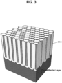
- FIG. 3 shows the porous thin film used to manufacture the mesh structure according to an embodiment.
- the porous thin film 110 includes a plurality of holes having very small diameters of a few nanometers to a few micrometers.
- anodic aluminum oxide having nanometer sized holes may be used.
- the type of the porous thin film or the size of the hole is not limited thereto and various types of porous thin films having holes of various sizes may be used.
- the metal layer 120 covers the remaining area B except the nozzle area A where droplets are sprayed through the holes on the surface of the porous thin film 110. Since the remaining area B is blocked by the metal layer 120, a liquid is only sprayed through the nozzle area A.
- the nozzle area A includes at least one hole, and the droplet sprayed through the nozzle area A has a very small size on the level of a few nanometers to a few micrometers. The droplet size may vary depending on the number of holes in the nozzle area A and the diameter of each hole.
- the size of a droplet passing through a hole is about twice larger than the diameter of the hole, and may become larger when the droplet and droplets of adjacent holes merge, so the actually sprayed droplet size is not equal to the hole size, but the sprayed droplet size may be adjusted by adjusting the size of the nozzle area in the mesh manufacturing process.
- nanometer sized droplets may be formed by using the porous thin film (AAO) including nanometer-level holes and limiting the size of the nozzle.
- the holes in the area B other than the nozzle may be partially filled with the metal material 130 to increase the strength of the mesh or selectively adjust the ultrasonic resonant frequency.
- the metal material in the hole may be grown using electroplating.
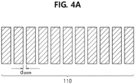
- a porous thin film 110 having a multi-hole structure is provided as shown in FIG. 4A .
- the porous thin film 110 includes a plurality of holes, and the diameter d pore of each hole may be a few nanometers to a few micrometers.
- anodic aluminum oxide having nanometer-sized holes may be used as the porous thin film 110.
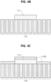
- a photosensitive layer 111 is formed on a part of the surface of the porous thin film 110 as shown in FIG. 4B .
- An area having the photosensitive layer is a nozzle area where droplets will be sprayed through the holes.
- a metal layer 120 is deposited, covering the porous thin film 110 and the photosensitive layer 111 as shown in FIG. 4C .
- the metal layer 120 may be deposited using the existing thin film deposition process, for example, chemical vapor deposition (CVD) and physical vapor deposition (PVD).
- the photosensitive layer 111 is removed from the porous thin film 110 to form a mesh structure.
- the area A in which the photosensitive layer 111 has been formed is exposed and the remaining area B is covered with the metal layer 120.
- the area A is the nozzle area where droplets are sprayed through the holes.
- the mesh structure 10 is formed through the process of FIGS. 4A to 4D , and an ultrasonic transducer 20 is combined with the mesh structure 10 to manufacture an atomizer according to an embodiment as shown in FIG. 4E .
- the ring type ultrasonic transducer 20 may be used.
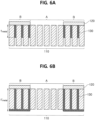
- FIGS. 5A and 5B are diagrams for describing a method for manufacturing a mesh structure with increased strength according to an embodiment.
- a metal material 130 is grown in the hole through oxidation and reduction of metal ions in an electrolyte as shown in FIG. 5B .
- the metal material is not grown in the area having the photosensitive layer 111 (later formed as the nozzle area), and the metal material in the hole is only grown in the remaining area. Accordingly, it is possible to increase the strength of the mesh structure while not inhibiting the liquid atomization function of the porous thin film.
- FIG. 7 shows a photographic image of the mesh type atomizer manufactured according to an embodiment and a scanning electron microscope (SEM) image of the nozzle area having the porous thin film structure.
- A shows the whole structure of the mesh type atomizer 1.
- B is an enlarged photographic image of the mesh structure 10 of the atomizer, and
- C is an enlarged photographic image of one of the nozzle areas A included in the mesh structure.
- one nozzle area includes a plurality of nanometer sized holes through which fine droplets having the size of a few nanometers are sprayed.
- the area other than the nozzle area is covered with the metal layer and droplets are not sprayed there.
- the mesh type atomizer described hereinabove it is possible to atomize a liquid into nanometer-level fine particles using the porous thin film including the nanometer sized holes. It is possible to precisely adjust the sprayed droplet size by setting the shape, size and interval of the nozzle in the manufacturing process, and it is possible to selectively increase the strength of the mesh by growing the metal material in the hole of the porous thin film through electroplating. It is possible to form much smaller droplets compared to the existing mesh drilled by laser drilling, and it can be used in various technical fields including medical nebulizers used to administer fine drug particles, fuel injection systems of automotive engines, filters or the like.
Landscapes
- Engineering & Computer Science (AREA)
- Health & Medical Sciences (AREA)
- Chemical & Material Sciences (AREA)
- Public Health (AREA)
- Veterinary Medicine (AREA)
- General Health & Medical Sciences (AREA)
- Animal Behavior & Ethology (AREA)
- Life Sciences & Earth Sciences (AREA)
- Hematology (AREA)
- Heart & Thoracic Surgery (AREA)
- Biomedical Technology (AREA)
- Anesthesiology (AREA)
- Physics & Mathematics (AREA)
- Electrochemistry (AREA)
- Chemical Kinetics & Catalysis (AREA)
- Organic Chemistry (AREA)
- Metallurgy (AREA)
- Materials Engineering (AREA)
- Optics & Photonics (AREA)
- Mechanical Engineering (AREA)
- Dispersion Chemistry (AREA)
- Pulmonology (AREA)
- Bioinformatics & Cheminformatics (AREA)
- Plasma & Fusion (AREA)
- Electromagnetism (AREA)
- Toxicology (AREA)
- Special Spraying Apparatus (AREA)
- Nozzles (AREA)
Claims (6)
- Verfahren zur Herstellung eines Maschenzerstäubers mit einer porösen Dünnschicht, umfassend:Bereitstellen einer porösen Dünnschicht (110) mit einer Mehrlochstruktur;Bilden einer fotosensitiven Schicht (111) auf einer Oberfläche der porösen Dünnschicht (110) in einem Düsenbereich, in dem Tröpfchen durch Löcher gesprüht werden sollen;Abscheiden einer Metallschicht (120) auf der porösen Dünnschicht (110) und der fotosensitiven Schicht (111);Entfernen der fotosensitiven Schicht (111) von der porösen Dünnschicht (110); undZusammenführen eines Ultraschallwandlers (20) mit der porösen Dünnschicht.
- Verfahren zur Herstellung eines Maschenzerstäubers mit einer porösen Dünnschicht nach Anspruch 1, des Weiteren umfassend:nach dem Abscheiden der Metallschicht (120) auf der porösen Dünnschicht (110) und der fotosensitiven Schicht (111),Verbinden eines galvanischen Metallmaterials (121) mit der Metallschicht (120); undZüchten eines Metallmaterials (130) in dem Loch eines übrigen Bereichs (B) ausschließlich des Düsenbereichs (A) nach einem galvanischen Verfahren.
- Verfahren zur Herstellung eines Maschenzerstäubers mit einer porösen Dünnschicht nach Anspruch 1 oder 2, wobei das Loch der porösen Dünnschicht einen Durchmesser von wenigen Nanometern bis wenigen Mikrometern aufweist.
- Verfahren zur Herstellung eines Maschenzerstäubers mit einer porösen Dünnschicht nach Anspruch 3, wobei die poröse Dünnschicht (110) aus anodischem Aluminiumoxid gebildet ist.
- Verfahren zur Herstellung eines Maschenzerstäubers mit einer porösen Dünnschicht nach einem der Ansprüche 1 bis 4, wobei der Düsenbereich (A) mindestens ein Loch umfasst und das durch den Düsenbereich (A) gesprühte Tröpfchen einen Durchmesser von wenigen Nanometern bis wenigen Mikrometern aufweist.
- Verfahren zur Herstellung eines Maschenzerstäubers mit einer porösen Dünnschicht nach Anspruch 5, wobei ein Abstand zwischen dem Düsenbereich und einem benachbarten Düsenbereich derart eingestellt ist, dass ein Verschmelzen von in den Düsenbereichen jeweils versprühten Tröpfchen verhindert ist.
Applications Claiming Priority (1)
| Application Number | Priority Date | Filing Date | Title |
|---|---|---|---|
| KR1020210010201A KR102581043B1 (ko) | 2021-01-25 | 2021-01-25 | 다공성 박막을 이용한 메쉬형 분무 장치 및 이의 제조방법 |
Publications (3)
| Publication Number | Publication Date |
|---|---|
| EP4032619A1 EP4032619A1 (de) | 2022-07-27 |
| EP4032619B1 true EP4032619B1 (de) | 2025-04-16 |
| EP4032619C0 EP4032619C0 (de) | 2025-04-16 |
Family
ID=77499738
Family Applications (1)
| Application Number | Title | Priority Date | Filing Date |
|---|---|---|---|
| EP21193052.4A Active EP4032619B1 (de) | 2021-01-25 | 2021-08-25 | Maschenzerstäuber mit porösem dünnem film und verfahren zur herstellung davon |
Country Status (3)
| Country | Link |
|---|---|
| US (1) | US20220234301A1 (de) |
| EP (1) | EP4032619B1 (de) |
| KR (1) | KR102581043B1 (de) |
Families Citing this family (2)
| Publication number | Priority date | Publication date | Assignee | Title |
|---|---|---|---|---|
| CN116251174B (zh) * | 2022-12-23 | 2023-09-29 | 北京三元基因药业股份有限公司 | 一种包含人干扰素α1b吸入溶液的药物组件 |
| KR20240157457A (ko) * | 2023-04-25 | 2024-11-01 | (주)포인트엔지니어링 | 양극산화막을 이용한 부품 및 그 제조방법 |
Family Cites Families (13)
| Publication number | Priority date | Publication date | Assignee | Title |
|---|---|---|---|---|
| US3790079A (en) * | 1972-06-05 | 1974-02-05 | Rnb Ass Inc | Method and apparatus for generating monodisperse aerosol |
| JPS55132513A (en) | 1979-04-03 | 1980-10-15 | Mitsubishi Electric Corp | Magnetic disc unit |
| JPS6068071A (ja) * | 1983-09-21 | 1985-04-18 | Matsushita Electric Ind Co Ltd | 霧化ポンプ |
| JPS6415953U (de) | 1987-07-10 | 1989-01-26 | ||
| US8616195B2 (en) * | 2003-07-18 | 2013-12-31 | Novartis Ag | Nebuliser for the production of aerosolized medication |
| DE102008055123B3 (de) * | 2008-12-23 | 2010-07-22 | Robert Bosch Gmbh | Ultraschallwandler zum Einsatz in einem fluiden Medium |
| DE102008055126A1 (de) * | 2008-12-23 | 2010-07-01 | Robert Bosch Gmbh | Ultraschallwandler zum Einsatz in einem fluiden Medium |
| TWM425720U (en) * | 2011-11-08 | 2012-04-01 | Microbase Technology Corp | Atomization structure |
| RU2637737C2 (ru) * | 2012-06-11 | 2017-12-06 | Стэмфорд Девайсиз Лимитед | Способ изготовления дырчатой пластины для распылителя |
| KR102184454B1 (ko) * | 2014-08-25 | 2020-11-30 | 삼성전자주식회사 | 초음파 변환기 모듈, 초음파 변환기 및 초음파 변환기의 제조 방법 |
| KR20170137431A (ko) * | 2016-06-03 | 2017-12-13 | 광운대학교 산학협력단 | 다공성 이중막 및 그의 제조방법 |
| KR102366002B1 (ko) * | 2018-05-23 | 2022-02-22 | (주)포인트엔지니어링 | 압전물질을 이용한 전자 장치 및 그 제조 방법 |
| CN210474459U (zh) * | 2019-07-30 | 2020-05-08 | 深圳梵活能源科技有限公司 | 一种聚酰亚胺膜结构雾化片 |
-
2021
- 2021-01-25 KR KR1020210010201A patent/KR102581043B1/ko active Active
- 2021-08-25 EP EP21193052.4A patent/EP4032619B1/de active Active
- 2021-08-26 US US17/412,265 patent/US20220234301A1/en active Pending
Also Published As
| Publication number | Publication date |
|---|---|
| KR20220107498A (ko) | 2022-08-02 |
| EP4032619C0 (de) | 2025-04-16 |
| US20220234301A1 (en) | 2022-07-28 |
| KR102581043B1 (ko) | 2023-09-22 |
| EP4032619A1 (de) | 2022-07-27 |
Similar Documents
| Publication | Publication Date | Title |
|---|---|---|
| US11905615B2 (en) | Photodefined aperture plate and method for producing the same | |
| EP2886185A1 (de) | Perforierte Membran und Verfahren zu ihrer Herstellung | |
| JP4500477B2 (ja) | 改良されたアパーチャプレートならびにその構築および使用のための方法 | |
| EP4032619B1 (de) | Maschenzerstäuber mit porösem dünnem film und verfahren zur herstellung davon | |
| JP2020096900A (ja) | ネブライザのための開口板を製造する方法 | |
| US11357931B2 (en) | Mesh for use in a nebuliser, and a method of manufacturing the same | |
| JP2015030881A (ja) | 開口プレート | |
| CN104302813B (zh) | 气溶胶发生器 | |
| JP6006647B2 (ja) | 噴霧機用メッシュおよびその製造方法 | |
| JP6244318B2 (ja) | 噴霧機用メッシュおよびその製造方法 | |
| HK1190367B (en) | Photodefined aperture plate and method for producing the same | |
| HK1205770B (en) | Aerosol generators | |
| HK1205770A1 (en) | Aerosol generators |
Legal Events
| Date | Code | Title | Description |
|---|---|---|---|
| PUAI | Public reference made under article 153(3) epc to a published international application that has entered the european phase |
Free format text: ORIGINAL CODE: 0009012 |
|
| STAA | Information on the status of an ep patent application or granted ep patent |
Free format text: STATUS: REQUEST FOR EXAMINATION WAS MADE |
|
| 17P | Request for examination filed |
Effective date: 20210915 |
|
| AK | Designated contracting states |
Kind code of ref document: A1 Designated state(s): AL AT BE BG CH CY CZ DE DK EE ES FI FR GB GR HR HU IE IS IT LI LT LU LV MC MK MT NL NO PL PT RO RS SE SI SK SM TR |
|
| RIN1 | Information on inventor provided before grant (corrected) |
Inventor name: SEONG, HYEJEONG Inventor name: PAHK, KI JOO Inventor name: PARK, JIN SOO Inventor name: KIM, DONG JUN Inventor name: SHIM, SHINYONG Inventor name: KANG, DONG-HYUN Inventor name: LEE, BYUNG CHUL |
|
| REG | Reference to a national code |
Ref country code: DE Ref legal event code: R079 Free format text: PREVIOUS MAIN CLASS: B05B0017000000 Ipc: B05B0017060000 Ref document number: 602021029153 Country of ref document: DE |
|
| GRAP | Despatch of communication of intention to grant a patent |
Free format text: ORIGINAL CODE: EPIDOSNIGR1 |
|
| STAA | Information on the status of an ep patent application or granted ep patent |
Free format text: STATUS: GRANT OF PATENT IS INTENDED |
|
| RIC1 | Information provided on ipc code assigned before grant |
Ipc: C25D 11/04 20060101ALN20241107BHEP Ipc: A61M 15/00 20060101ALN20241107BHEP Ipc: C25D 5/02 20060101ALI20241107BHEP Ipc: A61M 11/00 20060101ALI20241107BHEP Ipc: B05B 17/06 20060101AFI20241107BHEP |
|
| INTG | Intention to grant announced |
Effective date: 20241121 |
|
| GRAS | Grant fee paid |
Free format text: ORIGINAL CODE: EPIDOSNIGR3 |
|
| GRAA | (expected) grant |
Free format text: ORIGINAL CODE: 0009210 |
|
| STAA | Information on the status of an ep patent application or granted ep patent |
Free format text: STATUS: THE PATENT HAS BEEN GRANTED |
|
| AK | Designated contracting states |
Kind code of ref document: B1 Designated state(s): AL AT BE BG CH CY CZ DE DK EE ES FI FR GB GR HR HU IE IS IT LI LT LU LV MC MK MT NL NO PL PT RO RS SE SI SK SM TR |
|
| REG | Reference to a national code |
Ref country code: GB Ref legal event code: FG4D |
|
| REG | Reference to a national code |
Ref country code: CH Ref legal event code: EP Ref country code: DE Ref legal event code: R096 Ref document number: 602021029153 Country of ref document: DE |
|
| REG | Reference to a national code |
Ref country code: IE Ref legal event code: FG4D |
|
| U01 | Request for unitary effect filed |
Effective date: 20250512 |
|
| U07 | Unitary effect registered |
Designated state(s): AT BE BG DE DK EE FI FR IT LT LU LV MT NL PT RO SE SI Effective date: 20250516 |
|
| U20 | Renewal fee for the european patent with unitary effect paid |
Year of fee payment: 5 Effective date: 20250722 |
|
| PG25 | Lapsed in a contracting state [announced via postgrant information from national office to epo] |
Ref country code: ES Free format text: LAPSE BECAUSE OF FAILURE TO SUBMIT A TRANSLATION OF THE DESCRIPTION OR TO PAY THE FEE WITHIN THE PRESCRIBED TIME-LIMIT Effective date: 20250416 |
|
| PG25 | Lapsed in a contracting state [announced via postgrant information from national office to epo] |
Ref country code: GR Free format text: LAPSE BECAUSE OF FAILURE TO SUBMIT A TRANSLATION OF THE DESCRIPTION OR TO PAY THE FEE WITHIN THE PRESCRIBED TIME-LIMIT Effective date: 20250717 Ref country code: NO Free format text: LAPSE BECAUSE OF FAILURE TO SUBMIT A TRANSLATION OF THE DESCRIPTION OR TO PAY THE FEE WITHIN THE PRESCRIBED TIME-LIMIT Effective date: 20250716 |
|
| PG25 | Lapsed in a contracting state [announced via postgrant information from national office to epo] |
Ref country code: PL Free format text: LAPSE BECAUSE OF FAILURE TO SUBMIT A TRANSLATION OF THE DESCRIPTION OR TO PAY THE FEE WITHIN THE PRESCRIBED TIME-LIMIT Effective date: 20250416 |
|
| PG25 | Lapsed in a contracting state [announced via postgrant information from national office to epo] |
Ref country code: HR Free format text: LAPSE BECAUSE OF FAILURE TO SUBMIT A TRANSLATION OF THE DESCRIPTION OR TO PAY THE FEE WITHIN THE PRESCRIBED TIME-LIMIT Effective date: 20250416 |
|
| PG25 | Lapsed in a contracting state [announced via postgrant information from national office to epo] |
Ref country code: RS Free format text: LAPSE BECAUSE OF FAILURE TO SUBMIT A TRANSLATION OF THE DESCRIPTION OR TO PAY THE FEE WITHIN THE PRESCRIBED TIME-LIMIT Effective date: 20250716 |
|
| PG25 | Lapsed in a contracting state [announced via postgrant information from national office to epo] |
Ref country code: IS Free format text: LAPSE BECAUSE OF FAILURE TO SUBMIT A TRANSLATION OF THE DESCRIPTION OR TO PAY THE FEE WITHIN THE PRESCRIBED TIME-LIMIT Effective date: 20250816 |
|
| PG25 | Lapsed in a contracting state [announced via postgrant information from national office to epo] |
Ref country code: SM Free format text: LAPSE BECAUSE OF FAILURE TO SUBMIT A TRANSLATION OF THE DESCRIPTION OR TO PAY THE FEE WITHIN THE PRESCRIBED TIME-LIMIT Effective date: 20250416 |
|
| PG25 | Lapsed in a contracting state [announced via postgrant information from national office to epo] |
Ref country code: CZ Free format text: LAPSE BECAUSE OF FAILURE TO SUBMIT A TRANSLATION OF THE DESCRIPTION OR TO PAY THE FEE WITHIN THE PRESCRIBED TIME-LIMIT Effective date: 20250416 |
|
| PG25 | Lapsed in a contracting state [announced via postgrant information from national office to epo] |
Ref country code: SK Free format text: LAPSE BECAUSE OF FAILURE TO SUBMIT A TRANSLATION OF THE DESCRIPTION OR TO PAY THE FEE WITHIN THE PRESCRIBED TIME-LIMIT Effective date: 20250416 |