EP4032437A1 - Ausziehbares staubett - Google Patents
Ausziehbares staubett Download PDFInfo
- Publication number
- EP4032437A1 EP4032437A1 EP20865486.3A EP20865486A EP4032437A1 EP 4032437 A1 EP4032437 A1 EP 4032437A1 EP 20865486 A EP20865486 A EP 20865486A EP 4032437 A1 EP4032437 A1 EP 4032437A1
- Authority
- EP
- European Patent Office
- Prior art keywords
- drawer
- guide rail
- surrounding edge
- assembly
- pull
- Prior art date
- Legal status (The legal status is an assumption and is not a legal conclusion. Google has not performed a legal analysis and makes no representation as to the accuracy of the status listed.)
- Withdrawn
Links
- 230000007306 turnover Effects 0.000 claims description 10
- 230000003044 adaptive effect Effects 0.000 description 2
- 238000010586 diagram Methods 0.000 description 2
- 239000002184 metal Substances 0.000 description 2
- 239000000428 dust Substances 0.000 description 1
- 230000004048 modification Effects 0.000 description 1
- 238000012986 modification Methods 0.000 description 1
Images

Classifications
-
- A—HUMAN NECESSITIES
- A47—FURNITURE; DOMESTIC ARTICLES OR APPLIANCES; COFFEE MILLS; SPICE MILLS; SUCTION CLEANERS IN GENERAL
- A47C—CHAIRS; SOFAS; BEDS
- A47C17/00—Sofas; Couches; Beds
- A47C17/86—Parts or details specially adapted for beds, sofas or couches not fully covered by any single one of groups A47C17/02 - A47C17/84
-
- A—HUMAN NECESSITIES
- A47—FURNITURE; DOMESTIC ARTICLES OR APPLIANCES; COFFEE MILLS; SPICE MILLS; SUCTION CLEANERS IN GENERAL
- A47C—CHAIRS; SOFAS; BEDS
- A47C19/00—Bedsteads
- A47C19/02—Parts or details of bedsteads not fully covered in a single one of the following subgroups, e.g. bed rails, post rails
- A47C19/021—Bedstead frames
- A47C19/025—Direct mattress support frames, Cross-bars
-
- A—HUMAN NECESSITIES
- A47—FURNITURE; DOMESTIC ARTICLES OR APPLIANCES; COFFEE MILLS; SPICE MILLS; SUCTION CLEANERS IN GENERAL
- A47C—CHAIRS; SOFAS; BEDS
- A47C19/00—Bedsteads
- A47C19/22—Combinations of bedsteads with other furniture or with accessories, e.g. with bedside cabinets
Definitions
- the present disclosure relates to the technical field of furniture, in particular to a pull-out storage bed.
- the present disclosure provides a pull-out storage bed to solve the technical problem that a small-sized bedroom is not suitable for the placement of an electric bed due to the influence of space.
- the present disclosure provides the pull-out storage bed, and the pull-out storage bed includes an electric bed, a surrounding edge assembly, a supporting assembly and a drawer assembly.
- the surrounding edge assembly is of a hollow structure, and the supporting assembly is arranged in the hollow structure of the surrounding edge assembly.
- the electric bed is arranged on the surrounding edge assembly by means of the supporting assembly, and drawer openings through which the drawer assembly passes are formed in a periphery of the surrounding edge assembly.
- the size of the surrounding edge assembly is reduced, then through cooperation with the drawer assembly for storing articles, the floor area of the entire bed is reduced, the space for storing the articles is enlarged, and the space utilization is improved.
- the surrounding edge assembly includes a first surrounding edge, a second surrounding edge, a third surrounding edge and a fourth surrounding edge which are sequentially connected end to end.
- the first surrounding edge is parallel to the third surrounding edge
- the second surrounding edge is parallel to the fourth surrounding edge.
- the supporting assembly includes a first supporting rod, a second supporting rod and a third supporting rod, and two ends of the first supporting rod, two ends of the second supporting rod and two ends of the third supporting rod are respectively connected with the first surrounding edge and the third surrounding edge.
- the drawer openings include a first drawer opening and a second drawer opening
- the drawer assembly includes a first drawer, a second drawer, a first guide rail and a second guide rail.
- the first drawer opening is formed in the first surrounding edge
- the second drawer opening is formed in the third surrounding edge
- the first drawer opening directly faces the second drawer opening.
- the first guide rail is arranged on one side of the first drawer opening and the second drawer opening.
- the second guide rail is arranged on the other side of the first drawer opening and the second drawer opening. Horizontal heights of the first guide rail and the second guide rail are smaller than a height of the supporting assembly.
- the first drawer can be pulled out or pushed back relative to the first drawer opening by means of the first guide rail and the second guide rail
- the second drawer can be pulled out or pushed back relative to the second drawer opening by means of the first guide rail and the second guide rail.
- the drawer openings further include a third drawer opening
- the drawer assembly further includes a third drawer, a third guide rail and a fourth guide rail.
- the third drawer opening is formed in the second surrounding edge.
- One end of the third guide rail and one end of the fourth guide rail are respectively and perpendicularly connected with the second guide rail, and the other end of the third guide rail and the other end of the fourth guide rail are respectively fixed to two sides of the third drawer opening.
- the third drawer can be pulled out or pushed back relative to the third drawer opening by means of the third guide rail and the fourth guide rail.
- the drawer assembly further includes baffles which are arranged on the first guide rail and the second guide rail or on the third guide rail and the fourth guide rail.
- an outer wall of the fourth surrounding edge inclines inwards from top to bottom to form a slanted surface.
- the pull-out storage bed further includes a straight backrest which is vertically arranged on a top of the fourth surrounding edge.
- the electric bed includes a base, a turnover mechanism and a load-bearing mechanism.
- the load-bearing mechanism is horizontally arranged on a top face of the base.
- the turnover mechanism is arranged between the base and the load-bearing mechanism.
- the load-bearing mechanism can be partially turned over relative to the base by means of the turnover mechanism.
- the load-bearing mechanism includes a first bed board, a second bed board, a third bed board and a fourth bed board which are sequentially in pivot connection at junctions.
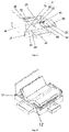
- Fig. 1 is a side view of a pull-out storage bed of an embodiment of the disclosure
- Fig. 2 is a schematic diagram of an internal structure of a pull-out storage bed of an embodiment of the disclosure.
- the pull-out storage bed provided by the present disclosure includes an electric bed 1, a surrounding edge assembly 2, a supporting assembly 3 and a drawer assembly 4.
- the surrounding edge assembly 2 is of a hollow structure
- the supporting assembly 3 is arranged in the hollow structure of the surrounding edge assembly 2.
- the electric bed 1 is arranged on the surrounding edge assembly 2 by means of the supporting assembly 3, and drawer openings through which the drawer assembly 4 passes are formed in a periphery of the surrounding edge assembly 2.
- a closed or semi-closed space is enclosed by the surrounding edge assembly 2, and by additionally forming the drawer openings in the side edges of the surrounding edge assembly 2 to serve as passages of the drawer assembly 4, the drawer assembly 4 can be used for storing articles.
- the drawer assembly 4 In a closed state, the drawer assembly 4 is located in the internal space of the surrounding edge assembly 2; and in an opened state, the drawer assembly 4 is partially or fully located outside the internal space of the surrounding edge assembly 2 to store and take out the articles.
- the surrounding edge assembly 2 is supported by the supporting assembly 3, so that the size of the surrounding edges can be reduced to reduce the floor area.
- the drawer assembly 4 is arranged in a bottom space of the entire bed, and thus storage space of a bedroom is increased and the space utilization is improved.
- the surrounding edge assembly 2 includes a first surrounding edge 21, a second surrounding edge 22, a third surrounding edge 23 and a fourth surrounding edge 24 which are sequentially connected end to end.
- the first surrounding edge 21 is parallel to the third surrounding edge 23, and the second surrounding edge 22 is parallel to the fourth surrounding edge 24.
- the semi-closed space is enclosed by the four independent surrounding edges to support the electric bed 1 and provide an invisible space for storing the articles, which can not only facilitate disassembly and assembly and transportation, but also beautify a bed body.
- the supporting assembly 3 includes a first supporting rod 31, a second supporting rod 32 and a third supporting rod 33. Two ends of the first supporting rod 31, two ends of the second supporting rod 32 and two ends of the third supporting rod 33 are respectively connected with the first surrounding edge 21 and the third surrounding edge 23.
- the first supporting rod 31, the second supporting rod 32 and the third supporting rod 33 are horizontally arranged in the internal space of the surrounding edge assembly 2 in a spaced manner to support the surrounding edge assembly 2 in case of deforming, and to place the electric bed 1.
- the specific position and number for the supporting rods can be adjusted according to actual needs, which is simple and convenient and facilitates disassembly and assembly.
- the drawer openings include a first drawer opening and a second drawer opening
- the drawer assembly 4 includes a first drawer 41, a second drawer 42, a first guide rail 43 and a second guide rail 44.
- the first drawer opening is formed in the first surrounding edge 21, the second drawer opening is formed in the third surrounding edge 23, and the first drawer opening directly faces the second drawer opening.
- the first guide rail 43 is arranged on one side of the first drawer opening and the second drawer opening, the second guide rail 44 is arranged on the other side of the first drawer opening and the second drawer opening.
- the horizontal heights of the first guide rail 43 and the second guide rail 44 are smaller than a height of the supporting assembly 3.
- the first drawer 41 can be pulled out or pushed back relative to the first drawer opening by means of the first guide rail 43 and the second guide rail 44, and the second drawer 42 can be pulled out or pushed back relative to the second drawer opening by means of the first guide rail 43 and the second guide rail 44.
- the first drawer 41 and the second drawer 42 are symmetrically arranged on the two sides of the surrounding edge assembly 2 to store the articles.
- the first drawer 41 and the second drawer 42 are arranged on the first guide rail 43 and the second guide rail 44 and can be pulled out or pushed back along the first guide rail 43 and the second guide rail 44, which is simple and convenient.
- the drawer openings further include a third drawer opening.
- the drawer assembly 4 further includes a third drawer 45, a third guide rail 46 and a fourth guide rail 47.
- the third drawer opening is formed in the second surrounding edge 22.
- One end of the third guide rail 46 and one end of the fourth guide rail 47 are respectively and perpendicularly connected with the second guide rail 44.
- the other ends of the third guide rail 46 and the other end of the fourth guide rail 47 are respectively fixed to two sides of the third drawer opening.
- the third drawer 45 can be pulled out or pushed back relative to the third drawer opening by means of the third guide rail 46 and the fourth guide rail 47.
- the storage space is further increased, and the space utilization is improved.
- the plurality of foregoing guide rails can be directly riveted on metal members used for mounting the guide rails by means of closed blind rivets, and the metal members are fixedly arranged on the corresponding surrounding edges to facilitate positioning during mounting.
- the horizontal heights of the bottom faces of the three drawers are slightly larger than that of the bottom face of the surrounding edge assembly 2, so that the drawers are not in contact with the bottom face of the surrounding edge assembly 2, which can prevent the drawers from being affected with damp and avoid noise generated by the friction with the bottom face of the surrounding edge assembly 2 when the drawers are pulled.
- the drawer assembly 4 further includes baffles 48 which are arranged on the first guide rail 43 and the second guide rail 44 or on the third guide rail 46 and the fourth guide rail 47.
- the corresponding baffles 48 are additionally arranged to shield the openings, so that dust and other garbage can be blocked.
- the outer wall of the fourth surrounding edge 24 inclines inwards from top to bottom to form a slanted surface.
- skirting boards are mounted at s of wall surfaces and the ground to make the whole look more beautiful and have a stereo sense, but this will produce a gap between the bed and the wall, leading the bed unable to be fully fitted to the wall and prone to shaking.
- the fourth surrounding edge 24 is tightly attached to the wall and shaking and damage is avoided.
- the pull-out storage bed also includes a straight backrest 5 which is vertically arranged on a top of the fourth surrounding edge 24.
- the contact area with the wall is increased, and the backrest 5 provides place for people to lean against. Furthermore, the stability of the entire bed is improved, bed shaking is reduced, clothes can also be avoided from getting dirty, and the appearance of the bed is improved.
- Fig. 3 is a perspective view of a pull-out storage bed of an embodiment of the disclosure.
- the electric bed 1 includes a base 11, a turnover mechanism and a load-bearing mechanism 12.
- the load-bearing mechanism 12 is horizontally arranged on a top face of the base 11, the turnover mechanism is arranged between the base 11 and the load-bearing mechanism 12, and the load-bearing mechanism 12 can be partially turned over relative to the base 11 by means of the turnover mechanism.
- the electric bed 1 drives the load-bearing mechanism 12 to move by means of the turnover mechanism, so that the shape of a bed surface is changed to adapt to the curve of a human body so as to make the human body fully supported and have a better rest, which enhances the comfort of the bed.
- the load-bearing mechanism 12 includes a first bed board, a second bed board, a third bed board and a fourth bed board which are sequentially in pivot connection at junctions.
- the load-bearing mechanism 12 are actually the bed boards, and the entire bed board of the electric bed 1 generally consists of the plurality of the bed boards that are in pivot connection. In this way, the load-bearing mechanism 12 can deform only by changing the angles of certain bed boards relative to the base 11, thus realizing a deformation function of the bed surface of the electric bed 1, which is simple and efficient.
Landscapes
- Health & Medical Sciences (AREA)
- General Health & Medical Sciences (AREA)
- Nursing (AREA)
- Drawers Of Furniture (AREA)
Applications Claiming Priority (2)
| Application Number | Priority Date | Filing Date | Title |
|---|---|---|---|
| CN201910882432.2A CN112515401A (zh) | 2019-09-18 | 2019-09-18 | 一种抽拉式储物床 |
| PCT/CN2020/080576 WO2021051768A1 (zh) | 2019-09-18 | 2020-03-23 | 一种抽拉式储物床 |
Publications (2)
| Publication Number | Publication Date |
|---|---|
| EP4032437A1 true EP4032437A1 (de) | 2022-07-27 |
| EP4032437A4 EP4032437A4 (de) | 2023-10-04 |
Family
ID=74883417
Family Applications (1)
| Application Number | Title | Priority Date | Filing Date |
|---|---|---|---|
| EP20865486.3A Withdrawn EP4032437A4 (de) | 2019-09-18 | 2020-03-23 | Ausziehbares staubett |
Country Status (3)
| Country | Link |
|---|---|
| EP (1) | EP4032437A4 (de) |
| CN (1) | CN112515401A (de) |
| WO (1) | WO2021051768A1 (de) |
Families Citing this family (1)
| Publication number | Priority date | Publication date | Assignee | Title |
|---|---|---|---|---|
| WO2023084459A1 (en) | 2021-11-15 | 2023-05-19 | Pfizer Inc. | Methods of treating sars-cov-2 |
Family Cites Families (9)
| Publication number | Priority date | Publication date | Assignee | Title |
|---|---|---|---|---|
| US2462524A (en) * | 1946-10-22 | 1949-02-22 | Mattedi Minnie | Bedstead |
| CN104433474A (zh) * | 2013-09-24 | 2015-03-25 | 成都市鑫木益居家具有限公司 | 一种新型床 |
| CN203953019U (zh) * | 2014-07-24 | 2014-11-26 | 刘文龙 | 床 |
| US20170042336A1 (en) * | 2015-08-11 | 2017-02-16 | Larry J. Craver | Ready-to-Assemble Bed Foundation Kit with Threaded Pin Assembly |
| CN205432948U (zh) * | 2015-12-29 | 2016-08-10 | 宿州学院 | 一种新型家用高档收纳床 |
| US20180064259A1 (en) * | 2016-09-07 | 2018-03-08 | Chuan-Hang Shih | Electric bed |
| TWM562064U (zh) * | 2018-01-23 | 2018-06-21 | Ulife Healthcare Inc | 具有抽屜之電動傢俱床 |
| US10750874B2 (en) * | 2017-12-22 | 2020-08-25 | Ulife Healthcare Inc. | Modular bed assembly |
| CN209058482U (zh) * | 2018-01-26 | 2019-07-05 | 邵阳市舒康美家具有限公司 | 一种床 |
-
2019
- 2019-09-18 CN CN201910882432.2A patent/CN112515401A/zh not_active Withdrawn
-
2020
- 2020-03-23 WO PCT/CN2020/080576 patent/WO2021051768A1/zh not_active Ceased
- 2020-03-23 EP EP20865486.3A patent/EP4032437A4/de not_active Withdrawn
Also Published As
| Publication number | Publication date |
|---|---|
| CN112515401A (zh) | 2021-03-19 |
| EP4032437A4 (de) | 2023-10-04 |
| WO2021051768A1 (zh) | 2021-03-25 |
Similar Documents
| Publication | Publication Date | Title |
|---|---|---|
| US8203854B2 (en) | Display suspending frame device, and assembly of the display suspending frame device, a display, and an electronic device | |
| KR101142161B1 (ko) | 서랍형 침대 프레임 | |
| CN200938944Y (zh) | 可装嵌拆卸的金属储物柜 | |
| EP4032437A1 (de) | Ausziehbares staubett | |
| KR200498377Y1 (ko) | 운송과 조립에 편리한 접이식 거치대 | |
| KR200448107Y1 (ko) | 책상일체형 침대 | |
| CN211021807U (zh) | 一种抽拉式储物床 | |
| KR101460583B1 (ko) | 시스템 가구 | |
| JP2594654Y2 (ja) | 間口方向に伸縮可能な収納家具 | |
| CN213820668U (zh) | 一种储物床架 | |
| JP3140725B2 (ja) | 引き出し支持構造 | |
| CN101004315A (zh) | 可组合的冰箱用双层搁架 | |
| CN205482086U (zh) | 搁物架及具有该搁物架的冰箱 | |
| CN209983844U (zh) | 一种多功能组合床 | |
| CN209068114U (zh) | 一种用于计算机的防震主机托盘 | |
| KR20240046813A (ko) | 침대 기능을 구비한 트레일러 | |
| TW201309439A (zh) | 工具櫃的斜立展示構造 | |
| CN211060462U (zh) | 冷柜及用于制冷设备的储存筐组件 | |
| CN210783725U (zh) | 互动型抽拉景观展现装置 | |
| CN209417377U (zh) | 多芯光缆交接箱 | |
| CN221469496U (zh) | 组合式公寓床 | |
| US20120090511A1 (en) | Table and storage system for coolers | |
| CN207940531U (zh) | 一种可翻转多功能沙发床 | |
| KR100658514B1 (ko) | 수납장과 책상을 겸비한 침대 | |
| CN218186054U (zh) | 一种便于组装的展柜 |
Legal Events
| Date | Code | Title | Description |
|---|---|---|---|
| STAA | Information on the status of an ep patent application or granted ep patent |
Free format text: STATUS: THE INTERNATIONAL PUBLICATION HAS BEEN MADE |
|
| PUAI | Public reference made under article 153(3) epc to a published international application that has entered the european phase |
Free format text: ORIGINAL CODE: 0009012 |
|
| STAA | Information on the status of an ep patent application or granted ep patent |
Free format text: STATUS: REQUEST FOR EXAMINATION WAS MADE |
|
| 17P | Request for examination filed |
Effective date: 20220413 |
|
| AK | Designated contracting states |
Kind code of ref document: A1 Designated state(s): AL AT BE BG CH CY CZ DE DK EE ES FI FR GB GR HR HU IE IS IT LI LT LU LV MC MK MT NL NO PL PT RO RS SE SI SK SM TR |
|
| DAV | Request for validation of the european patent (deleted) | ||
| DAX | Request for extension of the european patent (deleted) | ||
| A4 | Supplementary search report drawn up and despatched |
Effective date: 20230831 |
|
| RIC1 | Information provided on ipc code assigned before grant |
Ipc: A47C 20/04 20060101ALI20230825BHEP Ipc: A47C 19/22 20060101AFI20230825BHEP |
|
| STAA | Information on the status of an ep patent application or granted ep patent |
Free format text: STATUS: THE APPLICATION IS DEEMED TO BE WITHDRAWN |
|
| 18D | Application deemed to be withdrawn |
Effective date: 20240403 |