EP4030243B1 - Verfahren zur kontrolle und zur herstellung von uhrwerk-spiralfedern - Google Patents
Verfahren zur kontrolle und zur herstellung von uhrwerk-spiralfedern Download PDFInfo
- Publication number
- EP4030243B1 EP4030243B1 EP21152144.8A EP21152144A EP4030243B1 EP 4030243 B1 EP4030243 B1 EP 4030243B1 EP 21152144 A EP21152144 A EP 21152144A EP 4030243 B1 EP4030243 B1 EP 4030243B1
- Authority
- EP
- European Patent Office
- Prior art keywords
- spiral
- blank
- predetermined
- frequency
- stiffness
- Prior art date
- Legal status (The legal status is an assumption and is not a legal conclusion. Google has not performed a legal analysis and makes no representation as to the accuracy of the status listed.)
- Active
Links
Images


Classifications
-
- G—PHYSICS
- G04—HOROLOGY
- G04D—APPARATUS OR TOOLS SPECIALLY DESIGNED FOR MAKING OR MAINTAINING CLOCKS OR WATCHES
- G04D7/00—Measuring, counting, calibrating, testing or regulating apparatus
- G04D7/10—Measuring, counting, calibrating, testing or regulating apparatus for hairsprings of balances
-
- G—PHYSICS
- G04—HOROLOGY
- G04D—APPARATUS OR TOOLS SPECIALLY DESIGNED FOR MAKING OR MAINTAINING CLOCKS OR WATCHES
- G04D7/00—Measuring, counting, calibrating, testing or regulating apparatus
- G04D7/12—Timing devices for clocks or watches for comparing the rate of the oscillating member with a standard
- G04D7/1207—Timing devices for clocks or watches for comparing the rate of the oscillating member with a standard only for measuring
- G04D7/1235—Timing devices for clocks or watches for comparing the rate of the oscillating member with a standard only for measuring for the control mechanism only (found from outside the clockwork)
- G04D7/125—Timing devices for clocks or watches for comparing the rate of the oscillating member with a standard only for measuring for the control mechanism only (found from outside the clockwork) for measuring frequency
-
- G—PHYSICS
- G04—HOROLOGY
- G04D—APPARATUS OR TOOLS SPECIALLY DESIGNED FOR MAKING OR MAINTAINING CLOCKS OR WATCHES
- G04D7/00—Measuring, counting, calibrating, testing or regulating apparatus
- G04D7/12—Timing devices for clocks or watches for comparing the rate of the oscillating member with a standard
- G04D7/1257—Timing devices for clocks or watches for comparing the rate of the oscillating member with a standard wherein further adjustment devices are present
- G04D7/1271—Timing devices for clocks or watches for comparing the rate of the oscillating member with a standard wherein further adjustment devices are present for the control mechanism only (from outside the clockwork)
- G04D7/1285—Timing devices for clocks or watches for comparing the rate of the oscillating member with a standard wherein further adjustment devices are present for the control mechanism only (from outside the clockwork) whereby the adjustment device works on the mainspring
Definitions
- the present invention relates to the field of control and manufacture of parts for watchmaking.
- the invention relates more particularly to a method of control and manufacture of watchmaking spiral springs, otherwise called resonators.
- Mechanical watch movements are regulated by means of a mechanical regulator comprising a resonator, i.e. an elastically deformable component whose oscillations determine the running of the watch.
- a mechanical regulator comprising a resonator, i.e. an elastically deformable component whose oscillations determine the running of the watch.
- a regulator comprising a hairspring as a resonator, mounted on the axis of a balance wheel and set into oscillation by an escapement.
- the natural frequency of the balance wheel-hairspring pair is used to regulate the watch and depends in particular on the stiffness of the hairspring.
- the stiffness of the hairspring also defines its intrinsic vibrational characteristics, such as the natural frequency and the resonance frequencies.
- the natural frequency of an elastic system (a resonator alone or a resonator-balance pair) is the frequency at which this system oscillates when it is in free evolution, that is to say without an exciting force.
- a resonance frequency of an elastic system subjected to an exciting force is a frequency at which a local maximum of displacement amplitude can be measured for a given point. of the elastic system.
- the displacement amplitude follows an upward slope before this resonance frequency, and follows a downward slope afterwards, at any point which does not correspond to a vibration node.
- the recording of the displacement amplitude as a function of the excitation frequency presents a displacement amplitude peak or resonance peak which is associated with or which characterizes the resonance frequency.
- the natural frequency of the regulating organ formed by the hairspring of stiffness R coupled to a balance wheel of inertia I is notably proportional to the square root of the stiffness of the hairspring.
- the main specification of a spiral spring is its stiffness, which must be within a well-defined interval in order to be able to be paired with a balance wheel, which forms the inertial element of the oscillator. This pairing operation is essential to precisely adjust the frequency of a mechanical oscillator.
- silicon balance springs can be manufactured on a single wafer using micro-fabrication technologies. It is known in particular to produce a plurality of silicon resonators with very high precision using photolithography and machining/etching processes in a silicon wafer.
- the processes for producing these mechanical resonators generally use monocrystalline silicon wafers, but wafers made of other materials can also be used, for example polycrystalline or amorphous silicon, other semiconductor materials, glass, ceramic, carbon, carbon nanotubes or a composite comprising these materials.
- monocrystalline silicon belongs to the cubic crystalline class m3m whose thermal expansion coefficient (alpha) is isotropic.
- Silicon has a very negative value of the first thermoelastic coefficient, and consequently, the stiffness of a silicon resonator, and therefore its natural frequency, varies greatly depending on the temperature.
- the documents EP1422436 , EP2215531 And WO2016128694 describe a spiral-type mechanical resonator made from a core (or two cores in the case of WO2016128694 ) in monocrystalline silicon and whose temperature variations of the Young's modulus are compensated by a layer of amorphous silicon oxide (SiO2) surrounding the core (or cores), the latter being one of the rare materials presenting a positive thermoelastic coefficient.
- SiO2 amorphous silicon oxide
- the final functional yield will be given by the number of hairsprings whose stiffness corresponds to the pairing interval, divided by the total number of hairsprings on the wafer.
- the micro-manufacturing steps, and more particularly the etching steps, used in the manufacture of hairsprings on a wafer typically result in a significant geometric dispersion between the dimensions of the hairsprings on the same wafer, and therefore a significant dispersion between their stiffnesses, notwithstanding that the etching pattern is the same for each hairspring.
- the measured stiffness dispersion normally follows a Gaussian distribution. In order to optimize the manufacturing yield, we are therefore interested in centering the mean of the Gaussian distribution on a nominal stiffness value and also in reducing the standard deviation of this Gaussian.
- the dispersion of stiffnesses is even greater between hairsprings of two wafers engraved at different times following the same process specifications. This phenomenon is shown in figure 1 where the dispersion curves of the stiffness Rd1, Rd2 and Rd3 for the hairsprings on three different plates are illustrated. Generally, for each plate the distribution of the stiffnesses R (in relation to the number of hairsprings N with this stiffness) follows the normal or Gaussian law, each dispersion curve being centered on its respective mean value Rm1, Rm2 and Rm3.
- the documents WO2015113973 And EP3181938 propose to remedy this problem by forming a hairspring with dimensions greater than the dimensions necessary to obtain a hairspring of a predetermined stiffness, by measuring the stiffness of this hairspring formed by coupling it with a balance wheel having a predetermined inertia, by calculating the thickness of material to be removed to obtain the dimensions necessary to obtain the hairspring with the predetermined stiffness, and by removing this thickness from the hairspring.
- the document EP3181939 proposes to remedy this same problem by forming a spiral according to dimensions smaller than the dimensions necessary to obtain a spiral of a predetermined stiffness, by determining the stiffness of this spiral formed by coupling it with a balance wheel having a predetermined inertia, by calculating the thickness of material to be added to obtain the dimensions necessary to obtain the balance spring with the predetermined stiffness, and by adding this thickness of material to the balance spring.
- the stiffness dispersion curve Rd1, Rd2, etc. can be recentered with respect to a nominal stiffness value Rnom.
- the document CH 281 496 A which relates to a device for automatically adjusting the frequency of a balance-oscillator system, discloses the excitation of a balance-spring in order to detect its deviation from the excitation (reference) frequency.
- the present invention aims to propose an approach free from the above drawbacks, which allows a faster production flow and/or with less risk of pollution(s), and/or a larger sampling, and/or a more precise measurement, and therefore a more individualized correction of the spirals of the wafer.
- the method according to the above implementation comprises a step of vibratory excitation of the hairspring or the hairspring blank and the measurement of a characteristic of a resonance frequency, to then deduce by prediction a stiffness and possibly whether a dimensional correction is necessary.
- the method according to the above implementation therefore makes it possible to test balance spring blanks during manufacture while limiting the risks of pollution or assembly errors. A dimensional correction (of section, height and/or thickness) is then possible.
- the method according to the above implementation also makes it possible to test finished balance springs, for example to carry out a classification by stiffness increments, in order to plan a pairing with a particular balance wheel.
- the frequency range of the spectrum obtained does not only depend on the source of vibration excitation but also on the sensor of the measuring instrument used.
- the frequency range is linked both to the excitation frequency range and to the frequency range over which the oscillation amplitude measuring instrument (vibrometer or other) is sensitive.
- the excitation frequency range will be chosen so as to include at least one resonance frequency of the balance spring or blank under test.
- the predetermined resonant frequency that the finished hairspring must exhibit may be a target natural frequency or a target resonant frequency, or a target natural frequency range, or a target resonant frequency range defined by a tolerance around a target value.
- the dimensional correction predicted by the prediction machine may typically be a correction of the section of the flexible bar forming the hairspring or the hairspring blank, i.e. a correction of either the height or the thickness, or both.
- the characteristic of a resonance frequency is a characteristic of the oscillatory response measured over a predetermined frequency range, comprising at least one resonance frequency.
- a characteristic is typically identified after processing a raw measurement signal (e.g. measuring the amplitudes or speeds or accelerations of displacement of certain points of the balance spring or balance spring blank), the processing possibly including for example a Fourier transform to identify resonance peaks and therefore resonance frequencies.
- the frequency range is applied simultaneously to a plurality of hairsprings or hairspring blanks.
- Speed is improved because the vibration excitation can typically be imposed on a wafer supporting several hundred hairspring blanks, which would for example still be attached to the wafer.
- the hairspring has at least two predetermined resonance frequencies, and the frequency range is predetermined to cover at least the two predetermined resonance frequencies. By covering or sweeping a wide frequency range, multiple resonance peaks (or resonance frequencies) can be measured, which can provide improved accuracy.
- step a comprises the use of a source, such as a piezoelectric source, making it possible to induce or impose an acoustic excitation on a slice of a wafer supporting the balance spring blank, or preferably on, or even under the balance spring or the balance spring blank to be specifically excited.
- a source such as a piezoelectric source
- the acoustic source can be coupled to an excitation cone chosen to excite at least one hairspring or a hairspring blank.
- the acoustic source can be coupled to an excitation cone chosen to excite at least a portion and preferably all of the hairspring blanks.
- step b comprises the use of an optical measuring means, such as a laser vibrometer by Doppler effect.
- step b is based on a measurement over time of an amplitude or a speed, or even an acceleration of movement of at least one point of the hairspring or the hairspring blank, preferably carried out at least partially during step a.
- Measurements of displacements or speeds in several directions allow better identification of resonance peaks and frequencies.
- the mode of vibration in response to vibrational excitation may vary.
- step b comprises a step of processing the measurement signal with for example a Fourier transform, to identify resonance peaks of displacement or speed or acceleration amplitude, and/or phase, as a function of the excitation frequency.
- the resonance frequency is identified based on the width of the resonance or amplitude peak, at half-height of the maximum value of the amplitude resonance peak.
- step c comprises a step of calculating a stiffness of the hairspring or the hairspring blank.
- the calculation of the stiffness makes it possible to determine with improved precision whether a dimensional correction is necessary, and of what value this correction must be. In addition, this also makes it possible to pre-size or choose a balance wheel to couple the hairspring once it is finished manufacturing.
- the method comprises a step: d. calculate, with the prediction machine, the dimensional modification (change of section, height and/or thickness) to be applied from the resonance frequency characteristic identified in step b.
- the prediction machine implements a polynomial formula to predict whether a dimensional correction is necessary.
- a polynomial formula for example, linear regression modeling can be performed.
- the prediction machine implements a classification carried out for example by a neural network to predict whether a dimensional correction is necessary.
- the prediction machine implements a classification based on a partitioning into k-means or k-medians to predict whether a dimensional correction is necessary.
- control method comprises a step of calculating, with the prediction machine, the dimensional modification to be applied to the balance spring blanks of each sector.
- step a comprises a step of modifying a direction of vibrational excitation over time, preferably in a direction pointing to the hairspring or hairspring blank whose resonance frequency characteristic is identified in step b.
- control method comprises a preliminary step of taking into account the material of the hairspring or the hairspring blank, and of adjusting a maximum amplitude of the vibration excitation and/or a frequency range of the predetermined frequency range as a function of the material of the hairspring or the hairspring blank.
- the frequency range obtained extends over a frequency range from 0 Hz to 100 kHz, preferably from 0 Hz to 50 kHz, more preferably from 0 Hz to 40 kHz, and very preferably from 10 kHz to 35 kHz.
- the applicant has noticed that the accuracy of the prediction was better for peaks or resonance frequencies located over a high frequency range. Indeed, if we focus on the stiffness, its influence on the resonance frequency is stronger in high frequency ranges (e.g. between 10 kHz to 35 kHz), so that the sensitivity and accuracy are better over this particular range.
- step a and step b are repeated at least several times for the same measurement point of the hairspring or hairspring blank.
- step a and step b are synchronized.
- Such synchronization provides the possibility of detecting a phase shift, or an attenuation, or a coupling, the taking into account of which can improve the accuracy of the prediction, or make it possible to adjust or recalibrate the source of vibration excitation.
- the dimensions can be corrected by removing or adding material.
- the hairspring or the hairspring blank is formed from silicon, or glass, or ceramic, or metal, or carbon nanotubes.
- the balance spring blank is formed on a wafer, with a plurality of other balance spring blanks.
- the measuring instrument that is sufficiently sensitive over the chosen frequency range, and ensuring that the vibrational behavior of the hairspring can be used over this chosen frequency range.
- Such a step of identifying reference points allows to eliminate points or areas which are nodes (i.e., immobile points) at one or more resonance frequencies.
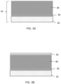
- FIGS. 3A-3F are a simplified representation of a method of manufacturing a mechanical resonator 100 on a wafer 10.
- the resonator is in particular intended to equip a regulating organ of a timepiece and, according to this example, is in the form of a silicon spiral spring 100 which is intended to equip a balance wheel of a mechanical timepiece movement.
- Plate 10 is illustrated in Figure 3A as a SOI (“silicon on insulator”) wafer and comprises a substrate or “handler” 20 carrying a sacrificial silicon oxide (SiO 2 ) layer 30 and a monocrystalline silicon layer 40.
- the substrate 20 may have a thickness of 500 ⁇ m
- the sacrificial layer 30 may have a thickness of 2 ⁇ m
- the silicon layer 40 may have a thickness of 120 ⁇ m.
- the monocrystalline silicon layer 40 may have any crystalline orientation.
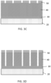
- FIG. 3B A lithography step is shown in Figures 3B And 3C .
- lithography we mean all the operations allowing transferring an image or pattern onto or above the wafer 10 to the latter.
- layer 40 is covered with a protective layer 50, for example made of a polymerizable resin.
- This layer 50 is structured, typically by a photolithography step using an ultraviolet light source as well as, for example, a photomask (or other type of exposure mask) or a stepper and reticle system. This lithographic structuring forms the patterns for the plurality of resonators in layer 50, as illustrated in Figure 3C .
- the patterns are machined, in particular etched, to form the plurality of resonators 100 in the layer 40.
- the etching can be carried out by a deep reactive ion etching technique (also known by the acronym DRIE for “Deep Reactive Ion Etching”). After the etching, the remaining portion of the protective layer 50 is subsequently removed.
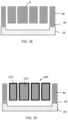
- the resonators are released from the substrate 20 by locally removing the sacrificial layer 30 or even by etching all or part of the silicon of the substrate or handler 20. Smoothing (not shown) of the etched surfaces can also take place before the release step, for example by a thermal oxidation step followed by a deoxidation step, consisting for example of wet etching based on hydrofluoric acid (HF).
- HF hydrofluoric acid
- the turns 110 of the silicon resonator 100 are covered with a layer 120 of silicon oxide (SiO2), typically by a thermal oxidation step to produce a thermo-compensated resonator.
- This layer 120 which generally has a thickness of 2-5 ⁇ m, also affects the final stiffness of the resonator and therefore must be taken into account during the previous steps to obtain vibrational characteristics of the hairspring leading to obtaining a particular natural frequency of the hairspring-balance pair in a given watch mechanism.
- the different resonators formed in the wafer generally exhibit significant geometric dispersion between them and therefore significant dispersion between their stiffnesses, notwithstanding that the steps of pattern formation and machining/engraving through these patterns are the same for all resonators.
- the above description relates to 100% silicon resonators, but it is possible to consider making the resonators in glass, ceramic, carbon nanotubes, or even metal.
- the resonators obtained in step 3E on the wafer 10 in question can be deliberately formed with dimensions d which are different from the dimensions required (for example greater) for obtaining a nominal or target stiffness.
- d the dimensions required (for example greater) for obtaining a nominal or target stiffness.
- the present invention proposes to determine from at least one characteristic of a resonance frequency of a sample of resonators 100 on the wafer in step 3E and whether a geometric correction of the resonators is necessary. If so, the present invention proposes to calculate precisely the thickness of material to be modified (to be removed or added), around each turn, to obtain the dimensions leading to obtaining the vibration characteristics of the resonators (natural frequency and/or resonance frequencies, and/or stiffness) corresponding to target values, according to a more efficient method than the methods of the prior art.
- a predictive method e.g. a numerical model or a classification or categorization method
- the modal properties of the spiral attached to the plate are thus exploited.
- a prediction machine by establishing a predictive model linking the dimensions (in particular the thickness) and/or the stiffness to certain frequencies (natural frequency or resonance frequencies associated with a resonance peak or a width at mid-height) specifically chosen.
- the learning phase is complete (once the modes to be exploited and the excitation frequencies have been determined), it is possible to move on to a prediction phase and use the prediction machine by exploiting the predictive model to control the resonators of a produced wafer, in order to predict whether a correction of the dimensions is necessary, and if so, calculate or predict the exact correction to be made to the dimensions of the resonators (by removal if the blank is produced with dimensions greater than the required final dimensions, or by addition of material if the blank is produced with dimensions smaller than the required final dimensions, for example).
- measurements can be performed following a particular sampling, for example according to a sampling range of 4, 2 or 1 Hz.
- the resolution for processing the acquisition data according to, for example, a Fourier transform depends directly on the duration of this acquisition.
- a signal sampling frequency of at least 100 kHz can be chosen if the frequency range extends up to 50 kHz for example.
- acoustic source to a divergent cone directed towards the resonators to be excited, and to adjust the acoustic source to emit an excitation signal with an amplitude sufficient to impose a vibrational excitation of the resonator(s) and having an amplitude sufficient to be detected and measured precisely by the chosen measuring instruments.
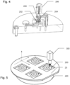
- FIG. 5 schematically represents a silicon wafer 25 on which a plurality of balance spring blanks 200 are formed.
- a vibration excitation source 400 is coupled to the wafer 25, so as to be able to impose a vibration excitation. Consequently, each balance spring blank 200 will vibrate, and a laser vibrometer 300, here focused on a point of the balance spring blank 200 on the right, will be able to measure the vibration amplitudes of the measurement point over time. It is possible to measure the displacements in a direction normal to the plane of the wafer 25, but it is just as possible to measure the displacements in one or more directions contained in the plane of the wafer 25.
- the laser vibrometer 300 can be moved to another measurement point on the balance spring blank 200, or moved to another balance spring blank 200 on the plate 25.
- the balance spring blank 200 can alternatively be moved relative to the laser vibrometer.
- FIG. 6 represents an example of vibrational excitation over time.
- the excitation frequency varies over time, between 0 Hz and 50 kHz, and a succession of rising edges can be imposed, each spaced by a rest period without excitation.
- a plurality of rising edges can be imposed (between 2 rising edges and 60 rising edges), each lasting between 0.5 s and 2 s for example.
- a step can be planned consisting of identifying points of the resonator for which the vibration response is significant. Indeed, in the case of a hairspring to which a vibration is imposed, especially if the frequency varies over time, the vibration response will cause nodes to appear on the hairspring, i.e. particular points of the hairspring whose displacement amplitude is low or zero. If a displacement measurement is carried out on a point of the hairspring which turns out to be a node at one or more particular frequency(ies), the identification of resonant frequency characteristics will be negatively affected.
- a preliminary step of measuring displacement on a plurality of predetermined points of the hairspring for example at least ten predetermined points, preferably at least twenty predetermined points, and very preferably at least thirty predetermined points. It is possible to provide for selecting the predetermined points arranged on an orthonormal X-Y reference frame in the plane of the hairspring.
- this preliminary step of measuring amplitude on the predetermined points it is possible to provide for identifying for each measurement point resonance frequencies, and then a step of selecting reference points for which the measurement of displacement amplitude during the excitation shows that they are not nodes at these resonance frequencies.
- the identified nodes have, at at least one resonance frequency, a displacement amplitude of zero or less than a first threshold peak value, and these points forming nodes are separated from the reference points to be considered for the subsequent measurements.
- the reference points are different depending on the position of the balance spring blank 200 on the plate 25.
- the reference points are far from the part anchored on the plate and naturally have a significant oscillatory displacement capacity, which ensures better precision of the displacement measurement.
- the displacements of a point on the body of the wafer, and/or a point on the excitation source can also be measured to identify or measure, for example, a phase shift or vibration attenuation, or a resonance resulting from vibration coupling or from the wafer.
- At least one resonance peak can be identified for each excited resonator, and it is proposed to determine the resonance frequency not on the basis of the peak of the resonance peak, i.e. on the maximum amplitude, but rather on an area of the curve located between 25% and 75% of the maximum amplitude value of the resonance peak, for example from its width at half-height.
- this processing method which focuses on a part of the curve between 25% and 75% of the maximum amplitude value of the resonance peak makes it possible to limit the errors due to the singularity of the maximum amplitude point and to the approximation calculations to reconstruct the summit part of the resonance peak.
- the area of the curve between 25% and 75% of the maximum amplitude value of the resonance peak has better accuracy than the part above 75% (typically the peak), which provides better accuracy on the exact resonance frequency determined.
- the middle of the segment connecting the two points at mid-height of the resonance peak can be taken to determine the resonance frequency associated with the peak in question.
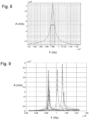
- FIG 7 represents an example of a vibration spectrum for a point of a 200 hairspring sketch of the figure 5 , reconstructed from the displacement amplitude measurements of the measurement point considered in response to the vibration excitation of the figure 6 , between 10 kHz and 15 kHz.
- Three amplitude peaks can be noted, at approximately 11 kHz, 12.3 kHz, and 13.7 kHz.
- Each amplitude peak has a resonance frequency, and the maximum amplitudes vary greatly.
- FIG 8 shows in detail the processing that can be done on an amplitude peak, for example at 11 kHz.
- the aim is to find the resonance frequency and to give it as precise a value as possible.
- the applicant has noticed that better precision can be achieved by determining the length of the segment connecting the rising part and the falling part of the curve, at mid-height of the peak.
- the resonance frequency is typically the value in the middle of this segment.
- an interpolation can be carried out on points in the vicinity of the resonance peak to improve the precision, and to shift the chosen point on the segment, which will not be the middle, in particular if the real position of the resonance peak is shifted for example because of the chosen sampling frequency.
- FIG 9 represents, for the example of an amplitude peak at approximately 10 kHz, the amplitude peaks constructed for about ten 200 balance spring blanks tested. It can be noted that from one balance spring blank to another, the frequency position of the amplitude peak varies (from approximately 9.8 kHz to 10.02 kHz), and that the maximum displacement amplitude varies in a ratio of approximately 1 to 5. Since the peaks of the amplitude peaks are not truly symmetrical, it seems judicious to determine the resonance frequency on the basis of the width of the peak at mid-height.
- a predetermined balance can be coupled directly to the resonator still attached to the plate, and a natural oscillation frequency of the resonator-balance pair can be measured to compare this natural frequency with an expected natural frequency and, above all, to calculate the stiffness actual or actual dimensions based on equations 1 to 3 above.
- the tested resonators can be finished manufacturing, in order to mount or couple them with a balance individually to measure here again a natural oscillation frequency of the resonator-balance pair.
- the stiffness can also be deduced from a measurement of the reaction torque at the collet using a rheometer.
- the acquired signal represents the evolution of the torque as a function of the amplitude. Analysis of the slope of this curve for low amplitudes (linear part) allows the stiffness to be deduced, and then the dimensions of the resonator bar. The dimensions of the hairspring bar can then be determined.
- a high-resolution 3D X-ray tomography approach would allow the extraction of point clouds giving the 3D material density of the hairsprings, and, by means of an adapted reconstruction of the images, a mapping of the hairspring section.
- Another approach is to analyze the forced oscillations of a balance spring on a reference balance with an escapement.
- a laser measurement of the passage times of the balance arms (point clouds), as presented above, makes it possible to measure the frequency and deduce the stiffness.
- An alternative can be considered from an acoustic acquisition (Witschi type microphone) which records the shocks of the different operating phases of the escapement/lever system.
- the measured data are either point clouds of the passage times of the balance arms, or the temporal evolution of the acoustic pressure level.
- oscillation amplitude measurements are performed on physical resonators, and resonance frequencies are identified.
- a correlation phase must be planned during which a predictive model is built.
- This database can also be supplemented by experimental measurements by measuring vibration spectra, oscillation periods and the positions of hairsprings on the plate as well as their associated stiffnesses.
- One of the advantages of this approach is that the learning database is enriched as the tests progress. This can make it possible to have an adaptive model according to the plates and hairsprings and contributes to the reduction of the standard deviation in stiffness on the plates.
- This database can be used to build a prediction model, and several solutions are offered.
- a numerical model for example polynomial, can be constructed to calculate, as a function of a resonance frequency value, a real thickness, a dimensional correction or a real stiffness.
- Categorization can also be performed by performing a k-means partitioning of the input data (the results of vibration measurements, typically the frequency of resonance peaks) and the output data (the stiffness, and/or the dimensions of the resonator bar) and linking them together to establish a correspondence.
- a neural network for example a perceptron
- a classification according to stiffness or dimensions of the bar, the classes being able to be defined by value increments.
- the learning phase includes a test phase (excitation of resonators with measurement of the vibration characteristics to reconstruct a vibration spectrum and identify resonance frequencies).
- a measurement phase of the stiffnesses and/or dimensions of the resonator bar is also carried out.
- the stiffness can therefore be predicted and compared with the actual measured stiffness as shown in the table below, with the first six rows being the data used to build or train the linear regression, and the last four rows being a prediction only: No. F (Hz) R (10 -7 N.mm) measured R (10 -7 N.mm) predicted gap 2 9824 3.89 3.84 -1.20% 9 9824 3.88 3.84 -1.10% 3 9840 3.92 3.87 -1.40% 8 9840 3.9 3.87 -0.90% 7 9848 3.91 3.88 -0.70% 4 9863 3.95 3.9 -1.20% Test 10 10020 4.111 4.136 0.60% 5 10121 4.135 4.288 3.70% 1 10129 4.119 4.3 4.40% 6 10148 4.196 4.328 3.20%
- the established prediction model has good sensitivity, i.e. that for two different input values, the model gives two distinct output values.
- the sensitivity of the prediction model is not the same for all resonance peaks.
- the slope coefficient is 0.0015 10 -7 N.mm/Hz.
- the leading coefficient could be larger for high resonance frequencies, which provides better prediction sensitivity, to predict distinct stiffness or dimensional correction values, even from values of close resonance frequencies.
- the resonance modes in particular the deformation and/or displacement modes of the resonators
- the resonance modes could differ significantly, which can also affect the sensitivity of the stiffness and/or dimensional correction prediction. It is advantageous to provide, during the learning phase, a step of comparing the sensitivity of the prediction in order to choose to subsequently consider this or that resonance frequency and not another in order to predict as accurately as possible a stiffness and/or a dimensional correction as a function of the vibration response.
- the learning phase makes it possible to choose either resonance peaks at high frequencies and/or resonance peaks which correspond to particular resonance modes making it possible to predict precise and reliable values, and the frequency range will be predetermined to include at least one resonance peak and preferably several, in order to be able to make either a single prediction as precise as possible, or several predictions (one per resonance peak deemed interesting) in order to then carry out cross-checks, averages or even adjustments of the predicted values.
- the inspection process can typically be performed on hairspring blanks made on a wafer and still attached to this wafer, so as to estimate the stiffness and/or the dimensions of the bar of the hairsprings of the sample, in order to determine whether a dimensional correction is necessary.
- step 1) and step 2) of the inspection process to check the spring stiffness/dimensions and confirm that the target values are met, within a tolerance threshold, or repeat these steps and the dimensional correction until the spring stiffness/dimensions predicted by the model reach the target values.
- corrections can be made for the entire plate in a homogeneous manner, or differentiated by region, if the results obtained vary from one hairspring to another. This allows the standard deviation of the dispersion of the stiffnesses to be reduced. Furthermore, if the stiffnesses of all the hairsprings are known by applying the model, the optimal correction can be determined to reduce the overall dispersion.
- the correction step then consists of adding material, as for example described in the document EP3181939 above-mentioned.
- the method consisting of identifying resonance frequencies by imposing a vibration excitation on the balance spring blanks alone, makes it possible to quickly obtain measurement data, without having to, for example, carry out balance wheel assembly operations, while limiting measurement errors because only the balance spring blank is tested (there is no error that could be linked to the balance wheel, such as its mass, assembly position, etc.).
Landscapes
- Physics & Mathematics (AREA)
- General Physics & Mathematics (AREA)
- Measurement Of Mechanical Vibrations Or Ultrasonic Waves (AREA)
- Micromachines (AREA)
- Testing Of Devices, Machine Parts, Or Other Structures Thereof (AREA)
Claims (19)
- Verfahren zur Kontrolle einer Spiralfeder oder eines Spiralfederrohlings, der eingerichtet ist, um eine Spiralfeder zu bilden, wobei die Spiralfeder mindestens eine vorbestimmte Resonanzfrequenz aufweisen muss, wobei das Kontrollverfahren die folgenden Schritte aufweist:a. Anwenden einer zeitlich variablen Schwingungsanregung auf die Spiralfeder oder den Spiralfederrohling, um einen vorbestimmten Frequenzbereich abzudecken,b. Identifizieren mindestens eines Merkmals einer Resonanzfrequenz, wie z. B. eines Resonanzpeaks, der Spiralfeder oder des Spiralfederrohlings bei der Schwingungsanregung auf den vorbestimmten Frequenzbereich,c. Unterziehen einer Vorhersagemaschine dem in Schritt b. identifizierten Resonanzfrequenzmerkmal, um eine Steifigkeit der Spiralfeder oder des Spiralfederrohlings zu bestimmen.
- Kontrollverfahren nach Anspruch 1, wobei Schritt c. ferner einen Schritt umfasst, der darin besteht vorherzusagen, ob eine Korrektur der Abmessung der Spiralfeder oder des Spiralfederrohlings notwendig ist, um die vorbestimmte Resonanzfrequenz zu erhalten.
- Kontrollverfahren nach Anspruch 1 oder 2, wobei der Frequenzbereich vorbestimmt ist, um mindestens einen Frequenzbereich einzubeziehen:- der auf die vorbestimmte Resonanzfrequenz zentriert ist, und- in einem Umfang von mindestens 30 % der vorbestimmten Resonanzfrequenz.
- Kontrollverfahren nach einem der Ansprüche 1 bis 3, wobei die Spiralfeder mindestens zwei vorbestimmte Resonanzfrequenzen aufweist, wobei der Frequenzbereich vorbestimmt ist, um mindestens die beiden vorbestimmten Resonanzfrequenzen abzudecken.
- Kontrollverfahren nach einem der Ansprüche 1 bis 4, wobei Schritt b. auf einer zeitlichen Messung einer Amplitude oder einer Geschwindigkeit oder einer Beschleunigung der Verlagerung mindestens eines Punktes der Spiralfeder oder des Spiralfederrohlings basiert, die vorzugsweise zumindest teilweise während Schritt a. durchgeführt wird.
- Kontrollverfahren nach einem der Ansprüche 1 bis 5, wobei die Spiralfeder oder der Spiralfederrohling in einer Basisebene enthalten ist, wobei Schritt b. umfasst:- einen Messschritt b' einer Amplitude oder einer Geschwindigkeit oder einer Beschleunigung der Verlagerung mindestens eines Punktes der Spiralfeder oder des Spiralfederrohlings in einer Richtung senkrecht zur Basisebene, und/oder- einen Messschritt b" einer Amplitude oder einer Geschwindigkeit oder einer Beschleunigung der Verlagerung mindestens eines Punktes der Spiralfeder oder des Spiralfederrohlings in einer in der Grundebene enthaltenen Richtung.
- Kontrollverfahren nach einem der Ansprüche 5 bis 6, wobei Schritt b. umfasst:- einen Schritt des Identifizierens eines Resonanzpeaks der Spiralfeder oder des Spiralfederrohlings in Abhängigkeit von einer Amplitude oder einer Verlagerungsgeschwindigkeit mindestens eines Punktes der Spiralfeder oder des Spiralfederrohlings.
- Kontrollverfahren nach Anspruch 7, wobei die Resonanzfrequenz auf der Basis der Breite des Resonanzpeaks auf halber Höhe des Maximalwerts des Resonanzpeaks identifiziert wird.
- Kontrollverfahren nach Anspruch 2 oder nach einem der Ansprüche 3 bis 8 in ihrer Abhängigkeit von Anspruch 2, wobei, wenn eine Korrektur der Abmessung notwendig ist, dann das Verfahren einen Schritt umfasst:
d. Berechnen der anzuwendenden Änderung der Abmessung mit der Vorhersagemaschine ausgehend von der in Schritt b. identifizierten Resonanzcharakteristik. - Kontrollverfahren nach einem der Ansprüche 1 bis 9, wobei die Vorhersagemaschine eine polynomiale Formel verwendet, um eine reale Steifigkeit vorherzusagen.
- Kontrollverfahren nach einem der Ansprüche 1 bis 9, wobei die Vorhersagemaschine eine Klassifizierung verwendet, die z. B. von einem neuronalen Netz durchgeführt wird, um eine reale Steifigkeit vorherzusagen.
- Kontrollverfahren nach einem der Ansprüche 1 bis 11, wobei der Spiralfederrohling auf einem Wafer gebildet wird, der eine Vielzahl von Spiralfederrohlingen umfasst, die über mehrere Sektoren des Wafers verteilt sind,wobei Schritt b. einen Schritt umfasst, der darin besteht, mindestens ein Merkmal einer Resonanzfrequenz von mindestens einem Spiralfederrohling für jeden Sektor zu identifizieren,und wobei Schritt c. einen Schritt umfasst, der darin besteht, für die Spiralfederrohlinge jedes Sektors eine Steifigkeit zu bestimmen.
- Kontrollverfahren nach einem der Ansprüche 1 bis 12, umfassend einen vorbereitenden Schritt, der darin besteht, das Material der Spiralfeder oder des Spiralfederrohlings zu berücksichtigen und eine maximale Amplitude der Schwingungsanregung und/oder einen Frequenzbereich des vorbestimmten Frequenzbereichs in Abhängigkeit von dem Material der Spiralfeder oder des Spiralfederrohlings einzustellen.
- Kontrollverfahren nach einem der Ansprüche 1 bis 13, wobei sich der Frequenzbereich über einen Frequenzbereich von 0 Hz bis 100 kHz, vorzugsweise von 0 Hz bis 50 kHz, besonders bevorzugt von 0 Hz bis 40 kHz und ganz besonders bevorzugt von 10 kHz bis 35 kHz erstreckt.
- Verfahren zur Herstellung einer Spiralfeder, die mindestens eine vorbestimmte Resonanzfrequenz aufweist, umfassend die Schritte, die darin bestehen:- Bilden mindestens einer Spiralfeder oder eines Spiralfederrohlings mit Abmessungen innerhalb vorbestimmter Toleranzen, die zum Erreichen der vorbestimmten Resonanzfrequenz notwendig sind,- Kontrollieren der Spiralfeder oder des Spiralfederrohlings gemäß dem Kontrollverfahren nach einem der vorhergehenden Ansprüche.
- Herstellungsverfahren nach vorhergehendem Anspruch, umfassend einen Schritt, der darin besteht:- Korrigieren mindestens einer Abmessung des in Schritt a. gebildeten Spiralfederrohlings gemäß der Berechnung in Schritt d. von Anspruch 9, um eine Spiralfeder mit der vorbestimmten Resonanzfrequenz zu erhalten.
- Herstellungsverfahren nach einem der Ansprüche 15 bis 16, wobei der Spiralfederrohlings auf einem Wafer zusammen mit einer Vielzahl anderer Spiralfederrohlinge gebildet wird.
- Verfahren zum Trainieren einer Vorhersagemaschine zur Durchführung von Schritt c. des Kontrollverfahrens nach einem der Ansprüche 1 bis 14, umfassend die Schritte, die darin bestehen:i- Bilden von Spiralfedern oder Spiralfederrohlingen,ii- Anwenden einer zeitlich variablen Schwingungsanregung auf jede der Spiralfedern oder jeden der Spiralfederrohlinge, um einen vorbestimmten Frequenzbereich abzudecken,iii- Identifizieren mindestens eines Merkmals einer Resonanzfrequenz jeder Spiralfeder oder jedes Spiralfederrohlings bei der Anwendung des vorbestimmten Frequenzbereichs,iv'- Anbringen einer Vielzahl von Spiralfedern oder von Spiralfederrohlingen in einem Schwingmechanismus, der eine vorbestimmte Trägheit aufweist, so dass für jede Spiralfeder oder jeden Spiralfederrohling eine freie Schwingungsfrequenz oder eine Steifigkeit gemessen wird,
und/oderiv"- Modellieren in einem Simulationswerkzeug einer Vielzahl von Spiralfedern oder von Spiralfederrohlingen in einem Schwingmechanismus, der eine vorbestimmte Trägheit aufweist, so dass für jede Spiralfeder oder jeden Spiralfederrohling eine freie Schwingungsfrequenz oder eine Steifigkeit berechnet wird.v- Bereitstellen, für die Vorhersagemaschine und für jede Spiralfeder oder jeden Rohling:- der in Schritt iii- identifizierten Resonanzfrequenzcharakteristik;- der in Schritt iv'- gemessenen und/oder in Schritt iv"- berechneten freien Schwingungsfrequenz oder Steifigkeit. - Trainingsverfahren nach vorhergehendem Anspruch, wobei Schritt iii- eine Vorphase der Identifizierung von Referenzmesspunkten umfasst mit:- dem Messen einer Verlagerung einer Vielzahl vorbestimmter Punkte der Spiralfeder oder des Spiralfederrohlings,- dem Identifizieren von Knoten aus der Vielzahl vorbestimmter Punkte, die bei mindestens einer Resonanzfrequenz oder -peak eine Verlagerungsamplitude von null oder unter einem ersten Schwellenpeakwert aufweisen,- dem Auswählen von bei der Kontrolle zu messenden Referenzpunkten aus der Vielzahl vorbestimmter Punkte, die von den identifizierten Knoten verschieden sind und die vorzugsweise jeweils einen Verlagerungsamplitudenpeak aufweisen, der höher als ein zweiter Schwellenpeakwert ist.
Priority Applications (6)
| Application Number | Priority Date | Filing Date | Title |
|---|---|---|---|
| EP21152144.8A EP4030243B1 (de) | 2021-01-18 | 2021-01-18 | Verfahren zur kontrolle und zur herstellung von uhrwerk-spiralfedern |
| JP2023542990A JP2024507061A (ja) | 2021-01-18 | 2022-01-14 | 時計用ぜんまいばねの試験及び製造方法 |
| CN202280010309.1A CN116783558A (zh) | 2021-01-18 | 2022-01-14 | 一种钟表游丝的检测和制造方法 |
| EP22700645.9A EP4278234B1 (de) | 2021-01-18 | 2022-01-14 | Verfahren zur kontrolle und zur herstellung von uhrwerk-spiralfedern |
| US18/261,472 US20240069496A1 (en) | 2021-01-18 | 2022-01-14 | Method for testing and manufacturing spiral springs for a timepiece |
| PCT/EP2022/050760 WO2022152857A1 (fr) | 2021-01-18 | 2022-01-14 | Procédé de controle et de fabrication de ressorts spiraux d'horlogerie |
Applications Claiming Priority (1)
| Application Number | Priority Date | Filing Date | Title |
|---|---|---|---|
| EP21152144.8A EP4030243B1 (de) | 2021-01-18 | 2021-01-18 | Verfahren zur kontrolle und zur herstellung von uhrwerk-spiralfedern |
Publications (2)
| Publication Number | Publication Date |
|---|---|
| EP4030243A1 EP4030243A1 (de) | 2022-07-20 |
| EP4030243B1 true EP4030243B1 (de) | 2024-09-25 |
Family
ID=74187192
Family Applications (2)
| Application Number | Title | Priority Date | Filing Date |
|---|---|---|---|
| EP21152144.8A Active EP4030243B1 (de) | 2021-01-18 | 2021-01-18 | Verfahren zur kontrolle und zur herstellung von uhrwerk-spiralfedern |
| EP22700645.9A Active EP4278234B1 (de) | 2021-01-18 | 2022-01-14 | Verfahren zur kontrolle und zur herstellung von uhrwerk-spiralfedern |
Family Applications After (1)
| Application Number | Title | Priority Date | Filing Date |
|---|---|---|---|
| EP22700645.9A Active EP4278234B1 (de) | 2021-01-18 | 2022-01-14 | Verfahren zur kontrolle und zur herstellung von uhrwerk-spiralfedern |
Country Status (5)
| Country | Link |
|---|---|
| US (1) | US20240069496A1 (de) |
| EP (2) | EP4030243B1 (de) |
| JP (1) | JP2024507061A (de) |
| CN (1) | CN116783558A (de) |
| WO (1) | WO2022152857A1 (de) |
Families Citing this family (7)
| Publication number | Priority date | Publication date | Assignee | Title |
|---|---|---|---|---|
| EP4303668A1 (de) * | 2022-07-05 | 2024-01-10 | Richemont International S.A. | Verfahren zur bestimmung der steifigkeit einer spiralfeder |
| DE102023133827B4 (de) * | 2023-01-03 | 2024-12-05 | Damasko Präzisionstechnik GmbH & Co. KG | Optisches Messverfahren für archimedische Flachspiralen und Spiralfeder mit dafür optimierter Geometrie |
| EP4398046A1 (de) * | 2023-01-03 | 2024-07-10 | Damasko Präzisionstechnik GmbH & Co. KG | Optisches messverfahren für archimedische flachspiralen und spiralfeder mit dafür optimierter geometrie |
| EP4471508A1 (de) * | 2023-05-30 | 2024-12-04 | Richemont International S.A. | Verfahren zur messung oder detektion eines fehlers in einem uhrwerk |
| EP4553586A1 (de) | 2023-11-08 | 2025-05-14 | Patek Philippe SA Genève | Verfahren zur herstellung einer rückstellfeder mit genauer steifigkeit für einen uhrresonator |
| EP4582879A1 (de) | 2024-01-03 | 2025-07-09 | Richemont International S.A. | Vibrationsprüfvorrichtung für eine uhr |
| CN119514292B (zh) * | 2025-01-20 | 2025-04-25 | 中国航发湖南动力机械研究所 | 涡轴发动机外部管路振动评估方法及系统、设备、介质 |
Family Cites Families (18)
| Publication number | Priority date | Publication date | Assignee | Title |
|---|---|---|---|---|
| CH263072A (de) * | 1947-10-30 | 1949-08-15 | Greiner Rudolf | Einrichtung zur Eichung eines Gangreglers für ein Uhrwerk. |
| DE921320C (de) * | 1948-11-30 | 1954-12-16 | Epsylon Res & Dev Company Ltd | Vorrichtung zum Abstimmen von Unruhspiralen |
| CH281496A (de) * | 1949-01-04 | 1952-03-15 | Smith & Sons Ltd S | Einrichtung für das selbsttätige Regulieren der Frequenz eines Systems Unruhe-Spiralfeder. |
| CH347491A (de) * | 1957-06-08 | 1960-06-30 | Kienzle Uhrenfabriken Ag | Verfahren zum Abstimmen von Schwingsystemen von Uhren |
| CH1342866A4 (de) * | 1966-09-15 | 1969-08-29 | ||
| ATE307990T1 (de) | 2002-11-25 | 2005-11-15 | Suisse Electronique Microtech | Spiraluhrwerkfeder und verfahren zu deren herstellung |
| ATE501467T1 (de) | 2007-11-28 | 2011-03-15 | Manuf Et Fabrique De Montres Et De Chronometres Ulysse Nardin Le Locle S A | Mechanischer oszillator mit einem optimierten thermoelastischen koeffizienten |
| EP2565727A1 (de) * | 2011-09-05 | 2013-03-06 | Nivarox-FAR S.A. | Verfahren zum Zusammenbau einer Uhrteilgruppe von Unruh - Spiralfeder und Einstellung in der Schwingungsfrequenz |
| CN103105769B (zh) * | 2011-11-09 | 2015-10-28 | 天津海鸥表业集团有限公司 | 一种摆轮游丝系统周期及摆幅光电测量仪 |
| WO2015113973A1 (fr) | 2014-01-29 | 2015-08-06 | Cartier Création Studio Sa | Ressort spiral thermocompensé en céramique comprenant l' élément silicium dans sa composition et son procédé de réglage |
| JP6486697B2 (ja) * | 2014-02-26 | 2019-03-20 | シチズン時計株式会社 | ひげぜんまいの製造方法及びひげぜんまい |
| WO2016086138A1 (en) * | 2014-11-25 | 2016-06-02 | Stream Mosaic, Inc. | Improved process control techniques for semiconductor manufacturing processes |
| FR3032810B1 (fr) | 2015-02-13 | 2017-02-24 | Tronic's Microsystems | Oscillateur mecanique et procede de realisation associe |
| EP3181938B1 (de) | 2015-12-18 | 2019-02-20 | CSEM Centre Suisse d'Electronique et de Microtechnique SA - Recherche et Développement | Herstellungsverfahren einer spiralfeder mit einer vorbestimmten steifigkeit durch wegnahme von material |
| EP3181939B1 (de) | 2015-12-18 | 2019-02-20 | CSEM Centre Suisse d'Electronique et de Microtechnique SA - Recherche et Développement | Herstellungsverfahren einer spiralfeder mit einer vorbestimmten steifigkeit durch zugabe von material |
| EP3534222B1 (de) * | 2018-03-01 | 2025-11-05 | Rolex Sa | Herstellungsverfahren eines thermokompensierten oszillators |
| CH716605A1 (fr) * | 2019-09-16 | 2021-03-31 | Richemont Int Sa | Procédé de fabrication d'une pluralité de résonateurs sur une plaquette. |
| JP2025500967A (ja) * | 2021-12-22 | 2025-01-15 | リシュモン アンテルナシオナル ソシエテ アノニム | 時計用ひげぜんまいを試験及び製造するための方法 |
-
2021
- 2021-01-18 EP EP21152144.8A patent/EP4030243B1/de active Active
-
2022
- 2022-01-14 EP EP22700645.9A patent/EP4278234B1/de active Active
- 2022-01-14 WO PCT/EP2022/050760 patent/WO2022152857A1/fr not_active Ceased
- 2022-01-14 JP JP2023542990A patent/JP2024507061A/ja active Pending
- 2022-01-14 CN CN202280010309.1A patent/CN116783558A/zh active Pending
- 2022-01-14 US US18/261,472 patent/US20240069496A1/en active Pending
Also Published As
| Publication number | Publication date |
|---|---|
| EP4278234B1 (de) | 2024-12-18 |
| WO2022152857A1 (fr) | 2022-07-21 |
| EP4030243A1 (de) | 2022-07-20 |
| CN116783558A (zh) | 2023-09-19 |
| JP2024507061A (ja) | 2024-02-16 |
| EP4278234A1 (de) | 2023-11-22 |
| US20240069496A1 (en) | 2024-02-29 |
Similar Documents
| Publication | Publication Date | Title |
|---|---|---|
| EP4030243B1 (de) | Verfahren zur kontrolle und zur herstellung von uhrwerk-spiralfedern | |
| EP4031936B1 (de) | Verfahren zur herstellung einer mehrzahl von resonatoren in einem wafer | |
| EP4558866A1 (de) | Verfahren zum testen und herstellen von ausgleichsfedern für uhren | |
| WO2023117350A1 (fr) | Procédé de controle et de fabrication de ressorts spiraux d'horlogerie | |
| EP3071976B1 (de) | Sensor mit beweglichem empfindlichem element mit gemischtem vibrierendem und pendelartigem betrieb und verfahren zur steuerung solch eines sensors | |
| FR2827040A1 (fr) | Systeme d'elimination de decalage pour un gyroscope vibrant | |
| CH719668A2 (fr) | Procédé de fabrication de composants horlogers. | |
| EP4202576A1 (de) | Verfahren zur kontrolle und herstellung von uhrwerk-spiralfedern | |
| EP4567531A1 (de) | Verfahren zur überwachung und herstellung von trägheitselementen einer uhr | |
| EP4273632A1 (de) | Verfahren zur herstellung von uhrenkomponenten | |
| EP4589392A1 (de) | Verfahren zur steuerung von trägheitselementen einer uhr | |
| EP4185841B1 (de) | Verfahren zur kalibrierung eines vibrierenden inertialsensors | |
| EP4471508A1 (de) | Verfahren zur messung oder detektion eines fehlers in einem uhrwerk | |
| EP4030241A1 (de) | Verfahren zur herstellung von uhrwerk-spiralfedern | |
| WO2023066614A1 (fr) | Procede de determination d'une valeur de repere et procede de reglage d'une valeur de repere | |
| EP4614242A1 (de) | Herstellung und paarung von uhrenkomponenten | |
| HK40100807B (en) | Method for monitoring and manufacturing timepiece hairsprings | |
| HK40100807A (en) | Method for monitoring and manufacturing timepiece hairsprings | |
| CH719864A2 (fr) | Dispositif de détermination de la raideur d'un spiral. | |
| EP4575665A1 (de) | Verfahren zur herstellung von spiralfedern einer uhr | |
| CH721422A2 (fr) | Procédé de fabrication d'un lot de ressorts spiraux d'horlogerie | |
| EP4650882A1 (de) | Verfahren zur herstellung von uhren-spirux | |
| EP4459383A1 (de) | Erkennung eines defekts eines zahns einer uhrenkomponente | |
| EP4538807A1 (de) | Verfahren zur bestimmung eines signierten bezugswertes eines oszillators für eine uhr | |
| EP3889617A1 (de) | Verfahren zur steuerung eines sensors |
Legal Events
| Date | Code | Title | Description |
|---|---|---|---|
| PUAI | Public reference made under article 153(3) epc to a published international application that has entered the european phase |
Free format text: ORIGINAL CODE: 0009012 |
|
| STAA | Information on the status of an ep patent application or granted ep patent |
Free format text: STATUS: THE APPLICATION HAS BEEN PUBLISHED |
|
| AK | Designated contracting states |
Kind code of ref document: A1 Designated state(s): AL AT BE BG CH CY CZ DE DK EE ES FI FR GB GR HR HU IE IS IT LI LT LU LV MC MK MT NL NO PL PT RO RS SE SI SK SM TR |
|
| STAA | Information on the status of an ep patent application or granted ep patent |
Free format text: STATUS: REQUEST FOR EXAMINATION WAS MADE |
|
| 17P | Request for examination filed |
Effective date: 20230120 |
|
| RBV | Designated contracting states (corrected) |
Designated state(s): AL AT BE BG CH CY CZ DE DK EE ES FI FR GB GR HR HU IE IS IT LI LT LU LV MC MK MT NL NO PL PT RO RS SE SI SK SM TR |
|
| GRAP | Despatch of communication of intention to grant a patent |
Free format text: ORIGINAL CODE: EPIDOSNIGR1 |
|
| STAA | Information on the status of an ep patent application or granted ep patent |
Free format text: STATUS: GRANT OF PATENT IS INTENDED |
|
| INTG | Intention to grant announced |
Effective date: 20240502 |
|
| GRAS | Grant fee paid |
Free format text: ORIGINAL CODE: EPIDOSNIGR3 |
|
| GRAA | (expected) grant |
Free format text: ORIGINAL CODE: 0009210 |
|
| STAA | Information on the status of an ep patent application or granted ep patent |
Free format text: STATUS: THE PATENT HAS BEEN GRANTED |
|
| AK | Designated contracting states |
Kind code of ref document: B1 Designated state(s): AL AT BE BG CH CY CZ DE DK EE ES FI FR GB GR HR HU IE IS IT LI LT LU LV MC MK MT NL NO PL PT RO RS SE SI SK SM TR |
|
| REG | Reference to a national code |
Ref country code: GB Ref legal event code: FG4D Free format text: NOT ENGLISH |
|
| REG | Reference to a national code |
Ref country code: CH Ref legal event code: EP |
|
| REG | Reference to a national code |
Ref country code: DE Ref legal event code: R096 Ref document number: 602021019136 Country of ref document: DE |
|
| REG | Reference to a national code |
Ref country code: IE Ref legal event code: FG4D Free format text: LANGUAGE OF EP DOCUMENT: FRENCH Ref country code: NL Ref legal event code: FP |
|
| REG | Reference to a national code |
Ref country code: LT Ref legal event code: MG9D |
|
| PG25 | Lapsed in a contracting state [announced via postgrant information from national office to epo] |
Ref country code: NO Free format text: LAPSE BECAUSE OF FAILURE TO SUBMIT A TRANSLATION OF THE DESCRIPTION OR TO PAY THE FEE WITHIN THE PRESCRIBED TIME-LIMIT Effective date: 20241225 |
|
| PG25 | Lapsed in a contracting state [announced via postgrant information from national office to epo] |
Ref country code: GR Free format text: LAPSE BECAUSE OF FAILURE TO SUBMIT A TRANSLATION OF THE DESCRIPTION OR TO PAY THE FEE WITHIN THE PRESCRIBED TIME-LIMIT Effective date: 20241226 Ref country code: FI Free format text: LAPSE BECAUSE OF FAILURE TO SUBMIT A TRANSLATION OF THE DESCRIPTION OR TO PAY THE FEE WITHIN THE PRESCRIBED TIME-LIMIT Effective date: 20240925 |
|
| PG25 | Lapsed in a contracting state [announced via postgrant information from national office to epo] |
Ref country code: BG Free format text: LAPSE BECAUSE OF FAILURE TO SUBMIT A TRANSLATION OF THE DESCRIPTION OR TO PAY THE FEE WITHIN THE PRESCRIBED TIME-LIMIT Effective date: 20240925 |
|
| PG25 | Lapsed in a contracting state [announced via postgrant information from national office to epo] |
Ref country code: LV Free format text: LAPSE BECAUSE OF FAILURE TO SUBMIT A TRANSLATION OF THE DESCRIPTION OR TO PAY THE FEE WITHIN THE PRESCRIBED TIME-LIMIT Effective date: 20240925 |
|
| PG25 | Lapsed in a contracting state [announced via postgrant information from national office to epo] |
Ref country code: RS Free format text: LAPSE BECAUSE OF FAILURE TO SUBMIT A TRANSLATION OF THE DESCRIPTION OR TO PAY THE FEE WITHIN THE PRESCRIBED TIME-LIMIT Effective date: 20241225 |
|
| PG25 | Lapsed in a contracting state [announced via postgrant information from national office to epo] |
Ref country code: RS Free format text: LAPSE BECAUSE OF FAILURE TO SUBMIT A TRANSLATION OF THE DESCRIPTION OR TO PAY THE FEE WITHIN THE PRESCRIBED TIME-LIMIT Effective date: 20241225 Ref country code: NO Free format text: LAPSE BECAUSE OF FAILURE TO SUBMIT A TRANSLATION OF THE DESCRIPTION OR TO PAY THE FEE WITHIN THE PRESCRIBED TIME-LIMIT Effective date: 20241225 Ref country code: LV Free format text: LAPSE BECAUSE OF FAILURE TO SUBMIT A TRANSLATION OF THE DESCRIPTION OR TO PAY THE FEE WITHIN THE PRESCRIBED TIME-LIMIT Effective date: 20240925 Ref country code: GR Free format text: LAPSE BECAUSE OF FAILURE TO SUBMIT A TRANSLATION OF THE DESCRIPTION OR TO PAY THE FEE WITHIN THE PRESCRIBED TIME-LIMIT Effective date: 20241226 Ref country code: FI Free format text: LAPSE BECAUSE OF FAILURE TO SUBMIT A TRANSLATION OF THE DESCRIPTION OR TO PAY THE FEE WITHIN THE PRESCRIBED TIME-LIMIT Effective date: 20240925 Ref country code: BG Free format text: LAPSE BECAUSE OF FAILURE TO SUBMIT A TRANSLATION OF THE DESCRIPTION OR TO PAY THE FEE WITHIN THE PRESCRIBED TIME-LIMIT Effective date: 20240925 |
|
| REG | Reference to a national code |
Ref country code: AT Ref legal event code: MK05 Ref document number: 1727151 Country of ref document: AT Kind code of ref document: T Effective date: 20240925 |
|
| PGFP | Annual fee paid to national office [announced via postgrant information from national office to epo] |
Ref country code: NL Payment date: 20250121 Year of fee payment: 5 |
|
| PG25 | Lapsed in a contracting state [announced via postgrant information from national office to epo] |
Ref country code: IS Free format text: LAPSE BECAUSE OF FAILURE TO SUBMIT A TRANSLATION OF THE DESCRIPTION OR TO PAY THE FEE WITHIN THE PRESCRIBED TIME-LIMIT Effective date: 20250125 Ref country code: PT Free format text: LAPSE BECAUSE OF FAILURE TO SUBMIT A TRANSLATION OF THE DESCRIPTION OR TO PAY THE FEE WITHIN THE PRESCRIBED TIME-LIMIT Effective date: 20250127 |
|
| PGFP | Annual fee paid to national office [announced via postgrant information from national office to epo] |
Ref country code: DE Payment date: 20250121 Year of fee payment: 5 |
|
| PG25 | Lapsed in a contracting state [announced via postgrant information from national office to epo] |
Ref country code: SM Free format text: LAPSE BECAUSE OF FAILURE TO SUBMIT A TRANSLATION OF THE DESCRIPTION OR TO PAY THE FEE WITHIN THE PRESCRIBED TIME-LIMIT Effective date: 20240925 Ref country code: RO Free format text: LAPSE BECAUSE OF FAILURE TO SUBMIT A TRANSLATION OF THE DESCRIPTION OR TO PAY THE FEE WITHIN THE PRESCRIBED TIME-LIMIT Effective date: 20240925 |
|
| PG25 | Lapsed in a contracting state [announced via postgrant information from national office to epo] |
Ref country code: ES Free format text: LAPSE BECAUSE OF FAILURE TO SUBMIT A TRANSLATION OF THE DESCRIPTION OR TO PAY THE FEE WITHIN THE PRESCRIBED TIME-LIMIT Effective date: 20240925 |
|
| PG25 | Lapsed in a contracting state [announced via postgrant information from national office to epo] |
Ref country code: EE Free format text: LAPSE BECAUSE OF FAILURE TO SUBMIT A TRANSLATION OF THE DESCRIPTION OR TO PAY THE FEE WITHIN THE PRESCRIBED TIME-LIMIT Effective date: 20240925 Ref country code: AT Free format text: LAPSE BECAUSE OF FAILURE TO SUBMIT A TRANSLATION OF THE DESCRIPTION OR TO PAY THE FEE WITHIN THE PRESCRIBED TIME-LIMIT Effective date: 20240925 |
|
| PGFP | Annual fee paid to national office [announced via postgrant information from national office to epo] |
Ref country code: CH Payment date: 20250201 Year of fee payment: 5 |
|
| PG25 | Lapsed in a contracting state [announced via postgrant information from national office to epo] |
Ref country code: PL Free format text: LAPSE BECAUSE OF FAILURE TO SUBMIT A TRANSLATION OF THE DESCRIPTION OR TO PAY THE FEE WITHIN THE PRESCRIBED TIME-LIMIT Effective date: 20240925 Ref country code: CZ Free format text: LAPSE BECAUSE OF FAILURE TO SUBMIT A TRANSLATION OF THE DESCRIPTION OR TO PAY THE FEE WITHIN THE PRESCRIBED TIME-LIMIT Effective date: 20240925 |
|
| PGFP | Annual fee paid to national office [announced via postgrant information from national office to epo] |
Ref country code: FR Payment date: 20250128 Year of fee payment: 5 |
|
| PG25 | Lapsed in a contracting state [announced via postgrant information from national office to epo] |
Ref country code: IT Free format text: LAPSE BECAUSE OF FAILURE TO SUBMIT A TRANSLATION OF THE DESCRIPTION OR TO PAY THE FEE WITHIN THE PRESCRIBED TIME-LIMIT Effective date: 20240925 Ref country code: SK Free format text: LAPSE BECAUSE OF FAILURE TO SUBMIT A TRANSLATION OF THE DESCRIPTION OR TO PAY THE FEE WITHIN THE PRESCRIBED TIME-LIMIT Effective date: 20240925 |
|
| PGFP | Annual fee paid to national office [announced via postgrant information from national office to epo] |
Ref country code: GB Payment date: 20250128 Year of fee payment: 5 |
|
| REG | Reference to a national code |
Ref country code: DE Ref legal event code: R097 Ref document number: 602021019136 Country of ref document: DE |
|
| PG25 | Lapsed in a contracting state [announced via postgrant information from national office to epo] |
Ref country code: DK Free format text: LAPSE BECAUSE OF FAILURE TO SUBMIT A TRANSLATION OF THE DESCRIPTION OR TO PAY THE FEE WITHIN THE PRESCRIBED TIME-LIMIT Effective date: 20240925 |
|
| PLBE | No opposition filed within time limit |
Free format text: ORIGINAL CODE: 0009261 |
|
| STAA | Information on the status of an ep patent application or granted ep patent |
Free format text: STATUS: NO OPPOSITION FILED WITHIN TIME LIMIT |
|
| 26N | No opposition filed |
Effective date: 20250626 |
|
| PG25 | Lapsed in a contracting state [announced via postgrant information from national office to epo] |
Ref country code: SE Free format text: LAPSE BECAUSE OF FAILURE TO SUBMIT A TRANSLATION OF THE DESCRIPTION OR TO PAY THE FEE WITHIN THE PRESCRIBED TIME-LIMIT Effective date: 20240925 |
|
| PG25 | Lapsed in a contracting state [announced via postgrant information from national office to epo] |
Ref country code: LU Free format text: LAPSE BECAUSE OF NON-PAYMENT OF DUE FEES Effective date: 20250118 Ref country code: MC Free format text: LAPSE BECAUSE OF FAILURE TO SUBMIT A TRANSLATION OF THE DESCRIPTION OR TO PAY THE FEE WITHIN THE PRESCRIBED TIME-LIMIT Effective date: 20240925 |
|
| PG25 | Lapsed in a contracting state [announced via postgrant information from national office to epo] |
Ref country code: BE Free format text: LAPSE BECAUSE OF NON-PAYMENT OF DUE FEES Effective date: 20250131 |
|
| REG | Reference to a national code |
Ref country code: BE Ref legal event code: MM Effective date: 20250131 |