EP4030116A1 - Outdoor unit and refrigeration cycle device - Google Patents
Outdoor unit and refrigeration cycle device Download PDFInfo
- Publication number
- EP4030116A1 EP4030116A1 EP19944704.6A EP19944704A EP4030116A1 EP 4030116 A1 EP4030116 A1 EP 4030116A1 EP 19944704 A EP19944704 A EP 19944704A EP 4030116 A1 EP4030116 A1 EP 4030116A1
- Authority
- EP
- European Patent Office
- Prior art keywords
- refrigerant
- compressor
- flow rate
- flow path
- control valve
- Prior art date
- Legal status (The legal status is an assumption and is not a legal conclusion. Google has not performed a legal analysis and makes no representation as to the accuracy of the status listed.)
- Granted
Links
Images


Classifications
-
- F—MECHANICAL ENGINEERING; LIGHTING; HEATING; WEAPONS; BLASTING
- F25—REFRIGERATION OR COOLING; COMBINED HEATING AND REFRIGERATION SYSTEMS; HEAT PUMP SYSTEMS; MANUFACTURE OR STORAGE OF ICE; LIQUEFACTION SOLIDIFICATION OF GASES
- F25B—REFRIGERATION MACHINES, PLANTS OR SYSTEMS; COMBINED HEATING AND REFRIGERATION SYSTEMS; HEAT PUMP SYSTEMS
- F25B40/00—Subcoolers, desuperheaters or superheaters
-
- F—MECHANICAL ENGINEERING; LIGHTING; HEATING; WEAPONS; BLASTING
- F25—REFRIGERATION OR COOLING; COMBINED HEATING AND REFRIGERATION SYSTEMS; HEAT PUMP SYSTEMS; MANUFACTURE OR STORAGE OF ICE; LIQUEFACTION SOLIDIFICATION OF GASES
- F25B—REFRIGERATION MACHINES, PLANTS OR SYSTEMS; COMBINED HEATING AND REFRIGERATION SYSTEMS; HEAT PUMP SYSTEMS
- F25B2400/00—Component parts or details not otherwise provided for in this subclass
- F25B2400/13—Economisers
-
- F—MECHANICAL ENGINEERING; LIGHTING; HEATING; WEAPONS; BLASTING
- F25—REFRIGERATION OR COOLING; COMBINED HEATING AND REFRIGERATION SYSTEMS; HEAT PUMP SYSTEMS; MANUFACTURE OR STORAGE OF ICE; LIQUEFACTION SOLIDIFICATION OF GASES
- F25B—REFRIGERATION MACHINES, PLANTS OR SYSTEMS; COMBINED HEATING AND REFRIGERATION SYSTEMS; HEAT PUMP SYSTEMS
- F25B2400/00—Component parts or details not otherwise provided for in this subclass
- F25B2400/19—Pumping down refrigerant from one part of the cycle to another part of the cycle, e.g. when the cycle is changed from cooling to heating, or before a defrost cycle is started
-
- F—MECHANICAL ENGINEERING; LIGHTING; HEATING; WEAPONS; BLASTING
- F25—REFRIGERATION OR COOLING; COMBINED HEATING AND REFRIGERATION SYSTEMS; HEAT PUMP SYSTEMS; MANUFACTURE OR STORAGE OF ICE; LIQUEFACTION SOLIDIFICATION OF GASES
- F25B—REFRIGERATION MACHINES, PLANTS OR SYSTEMS; COMBINED HEATING AND REFRIGERATION SYSTEMS; HEAT PUMP SYSTEMS
- F25B2400/00—Component parts or details not otherwise provided for in this subclass
- F25B2400/23—Separators
-
- F—MECHANICAL ENGINEERING; LIGHTING; HEATING; WEAPONS; BLASTING
- F25—REFRIGERATION OR COOLING; COMBINED HEATING AND REFRIGERATION SYSTEMS; HEAT PUMP SYSTEMS; MANUFACTURE OR STORAGE OF ICE; LIQUEFACTION SOLIDIFICATION OF GASES
- F25B—REFRIGERATION MACHINES, PLANTS OR SYSTEMS; COMBINED HEATING AND REFRIGERATION SYSTEMS; HEAT PUMP SYSTEMS
- F25B2600/00—Control issues
- F25B2600/23—Time delays
-
- F—MECHANICAL ENGINEERING; LIGHTING; HEATING; WEAPONS; BLASTING
- F25—REFRIGERATION OR COOLING; COMBINED HEATING AND REFRIGERATION SYSTEMS; HEAT PUMP SYSTEMS; MANUFACTURE OR STORAGE OF ICE; LIQUEFACTION SOLIDIFICATION OF GASES
- F25B—REFRIGERATION MACHINES, PLANTS OR SYSTEMS; COMBINED HEATING AND REFRIGERATION SYSTEMS; HEAT PUMP SYSTEMS
- F25B2600/00—Control issues
- F25B2600/25—Control of valves
-
- F—MECHANICAL ENGINEERING; LIGHTING; HEATING; WEAPONS; BLASTING
- F25—REFRIGERATION OR COOLING; COMBINED HEATING AND REFRIGERATION SYSTEMS; HEAT PUMP SYSTEMS; MANUFACTURE OR STORAGE OF ICE; LIQUEFACTION SOLIDIFICATION OF GASES
- F25B—REFRIGERATION MACHINES, PLANTS OR SYSTEMS; COMBINED HEATING AND REFRIGERATION SYSTEMS; HEAT PUMP SYSTEMS
- F25B2700/00—Sensing or detecting of parameters; Sensors therefor
- F25B2700/19—Pressures
- F25B2700/193—Pressures of the compressor
- F25B2700/1931—Discharge pressures
-
- F—MECHANICAL ENGINEERING; LIGHTING; HEATING; WEAPONS; BLASTING
- F25—REFRIGERATION OR COOLING; COMBINED HEATING AND REFRIGERATION SYSTEMS; HEAT PUMP SYSTEMS; MANUFACTURE OR STORAGE OF ICE; LIQUEFACTION SOLIDIFICATION OF GASES
- F25B—REFRIGERATION MACHINES, PLANTS OR SYSTEMS; COMBINED HEATING AND REFRIGERATION SYSTEMS; HEAT PUMP SYSTEMS
- F25B2700/00—Sensing or detecting of parameters; Sensors therefor
- F25B2700/19—Pressures
- F25B2700/193—Pressures of the compressor
- F25B2700/1933—Suction pressures
Definitions
- the present disclosure relates to an outdoor unit and a refrigeration cycle apparatus.
- Japanese Patent Laying-Open No. 2014-01917 discloses a refrigeration apparatus having an intermediate injection flow path and a suction injection flow path.
- a portion of refrigerant flowing from a condenser toward an evaporator can be merged with the intermediate pressure refrigerant in a compressor using the intermediate injection flow path, and can also be merged with the low pressure refrigerant to be suctioned into the compressor in a suction flow path using the suction injection flow path. Accordingly, in a case where using the intermediate injection flow path leads to deterioration of operation efficiency, the suction injection flow path can be used to decrease the discharge temperature of the compressor.
- a pump down operation is an operation to transfer refrigerant from a load device to an outdoor unit and store the refrigerant therein, by placing an on-off valve or the like on a pipe through which liquid refrigerant flows in a main refrigerant circuit, and operating a compressor with the pipe being blocked.
- An object of the present disclosure is to provide an outdoor unit and a refrigeration cycle apparatus with reduced refrigerant recovery time during a pump down operation.
- the present disclosure relates to an outdoor unit of a refrigeration cycle apparatus, the outdoor unit being connectable to a load device including a first expansion device and an evaporator.
- the outdoor unit includes: a first flow path configured to form a circulation flow path through which refrigerant circulates, by being connected to the load device; a compressor and a condenser disposed on the first flow path; a second flow path configured to branch from a branch point on the first flow path downstream of the condenser in a direction in which the refrigerant circulates, and to return, to the compressor, the refrigerant that has passed through the condenser; a second expansion device, a receiver, and a flow rate control valve disposed on the second flow path in order from the branch point; and a heat exchanger having a first passage and a second passage and configured to exchange heat between the refrigerant flowing in the first passage and the refrigerant flowing in the second passage.
- the first passage of the heat exchanger is disposed between the condenser and the branch point on the first flow path.
- the second passage of the heat exchanger is disposed between the flow rate control valve and the compressor on the second flow path.
- the flow rate control valve is configured to adjust an exhaust flow rate of liquid refrigerant from the receiver.
- the outdoor unit of the present disclosure even when refrigerant recovery progresses and a condensation temperature becomes close to an outside air temperature during a pump down operation, the refrigerant is condensed with the efficiency of the heat exchanger being maintained. This can reduce time required for the refrigerant recovery.
- Fig. 1 is an overall configuration diagram of a refrigeration cycle apparatus according to the present embodiment. It should be noted that Fig. 1 functionally shows the connection relation and the arrangement configuration of devices in the refrigeration cycle apparatus, and does not necessarily show an arrangement in a physical space.
- a refrigeration cycle apparatus 1 includes an outdoor unit 2, a load device 3, and pipes 84 and 88.
- Outdoor unit 2 has a refrigerant outlet port PO2 and a refrigerant inlet port P12 for connecting to load device 3.
- Load device 3 has a refrigerant outlet port PO3 and a refrigerant inlet port P13 for connecting to outdoor unit 2.
- Pipe 84 connects refrigerant outlet port PO2 of outdoor unit 2 to refrigerant inlet port PI3 of load device 3.
- Pipe 88 connects refrigerant outlet port PO3 of load device 3 to refrigerant inlet port PI2 of outdoor unit 2.
- Outdoor unit 2 of refrigeration cycle apparatus 1 is connectable to load device 3.
- Outdoor unit 2 includes a compressor 10 having a suction port G1, a discharge port G2, and an intermediate pressure port G3, a condenser 20, a fan 22, a heat exchanger 30, and pipes 80 to 82 and 89.
- Heat exchanger 30 has a first passage H1 and a second passage H2, and is configured to exchange heat between refrigerant flowing in first passage H1 and the refrigerant flowing in second passage H2.
- Load device 3 includes a first expansion valve 50, an evaporator 60, pipes 85, 86, and 87, and an on-off valve 28.
- Evaporator 60 is configured to perform heat exchange between air and the refrigerant. In refrigeration cycle apparatus 1, evaporator 60 evaporates the refrigerant by absorbing heat from the air in a space to be cooled.
- First expansion valve 50 is, for example, a temperature expansion valve controlled independently of outdoor unit 2. It should be noted that first expansion valve 50 may be an electronic expansion valve which can decompress the refrigerant.
- On-off valve 28 is closed when load device 3 stops operation, to block the refrigerant.
- Compressor 10 compresses the refrigerant suctioned from pipe 89, and discharges the compressed refrigerant to pipe 80.
- Compressor 10 can arbitrarily change a drive frequency by inverter control.
- compressor 10 is provided with intermediate pressure port G3, and allows the refrigerant from intermediate pressure port G3 to flow into an intermediate portion of a compression process.
- Compressor 10 is configured to adjust a rotation speed according to a control signal from a controller 100. By adjusting the rotation speed of compressor 10, a circulation amount of the refrigerant is adjusted, and the capability of refrigeration cycle apparatus 1 can be adjusted.
- various types of compressors can be adopted, and for example, a compressor of scroll type, rotary type, screw type, or the like can be adopted.
- Condenser 20 is configured such that the high-temperature, high-pressure gas refrigerant discharged from compressor 10 performs heat exchange with outside air (heat dissipation). By this heat exchange, the refrigerant is condensed and transforms into a liquid phase.
- the refrigerant discharged from compressor 10 to pipe 80 is condensed and liquefied in condenser 20, and flows into pipe 81.
- Fan 22 for blowing the outside air is attached to condenser 20 in order to increase the efficiency of heat exchange.
- Fan 22 supplies condenser 20 with the outside air with which the refrigerant performs heat exchange in condenser 20. By adjusting the number of revolutions of fan 22, a refrigerant pressure on a discharge side of compressor 10 (a high pressure-side pressure) can be adjusted.
- the refrigerant used for a refrigerant circuit of refrigeration cycle apparatus 1 is CO 2 .
- another refrigerant may be used.
- condenser 20 a device which cools the refrigerant such as CO 2 in a supercritical state
- condenser 20 an amount of decrease from a reference temperature of the refrigerant in the supercritical state
- subcool an amount of decrease from a reference temperature of the refrigerant in the supercritical state
- a first flow path F1 from refrigerant inlet port PI2 to refrigerant outlet port PO2 via compressor 10, condenser 20, and first passage H1 of heat exchanger 30 forms, together with a first flow path F1 on which first expansion valve 50 and evaporator 60 of load device 3 are disposed, a circulation flow path through which the refrigerant circulates.
- this circulation flow path will also be referred to as a "main refrigerant circuit" of a refrigeration cycle.
- Outdoor unit 2 further includes pipes 91, 92, and 94 configured to cause the refrigerant to flow from a portion of the circulation flow path between an outlet of first passage H1 and refrigerant outlet port PO2 to an inlet of second passage H2, and pipe 96 configured to cause the refrigerant to flow from an outlet of second passage H2 to suction port G1 or intermediate pressure port G3 of compressor 10.
- a second flow path F2 that branches from the main refrigerant circuit and delivers the refrigerant to compressor 10 via second passage H2 will also be referred to as an "injection flow path".
- Outdoor unit 2 further includes a receiver 73 disposed on second flow path F2 and configured to store the refrigerant.
- a second expansion valve 71 is disposed between pipes 91 and 92, pipe 91 branching from the portion of the circulation flow path between the outlet of first passage H1 and refrigerant outlet port PO2, and pipe 92 connected to an inlet of receiver 73.
- Outdoor unit 2 further includes a degassing pipe 93 that connects a gas exhaust outlet of receiver 73 to second passage H2 and is configured to exhaust a refrigerant gas within receiver 73, a throttle device 70 disposed between degassing pipe 93 and pipe 94 leading to second passage H2, and a flow rate control valve 72 configured to adjust a flow rate of the refrigerant in pipe 94 connected to a liquid refrigerant exhaust outlet of receiver 73.
- Pipe 91 is a pipe that branches from the main refrigerant circuit and causes the refrigerant to flow into receiver 73.
- Second expansion valve 71 is an electronic expansion valve which can decrease the pressure of the refrigerant at a high pressure portion of the main refrigerant circuit to an intermediate pressure.
- Receiver 73 is a container in which the refrigerant decompressed and having two phases is separated into a gas phase and a liquid phase, and which can store the refrigerant and adjust the circulation amount of the refrigerant in the main refrigerant circuit.
- Degassing pipe 93 connected to an upper portion of receiver 73 and pipe 94 connected to a lower portion of receiver 73 are pipes for taking out the refrigerant separated into gas refrigerant and liquid refrigerant within receiver 73, in a separated state.
- Flow rate control valve 72 adjusts the amount of the liquid refrigerant to be exhausted from pipe 94, and thereby can adjust the amount of the refrigerant in receiver 73.
- receiver 73 By providing receiver 73 on the injection flow path as described above, it becomes easy to ensure a subcool in pipes 82 and 83 which are liquid pipes. This is because, since receiver 73 generally includes the gas refrigerant therein and a refrigerant temperature reaches a saturation temperature, it is not possible to ensure a subcool if receiver 73 is disposed on pipe 82.
- receiver 73 is provided at an intermediate pressure portion, it becomes possible to store the intermediate pressure liquid refrigerant within receiver 73 even when the pressure at the high pressure portion of the main refrigerant circuit is high and the refrigerant is in the supercritical state.
- the design pressure of the container of receiver 73 can be set to be lower than that of the high pressure portion, and cost reduction by thinning the container can also be achieved.
- Outdoor unit 2 further includes pressure sensors 110 and 111, temperature sensors 120 to 123, and controller 100 configured to control compressor 10, second expansion valve 71, and flow rate control valve 72.
- Pressure sensor 110 detects a pressure PL at the suction port portion of compressor 10, and outputs a detection value thereof to controller 100.
- Pressure sensor 111 detects a discharge pressure PH of compressor 10, and outputs a detection value thereof to controller 100.
- Temperature sensor 120 detects a discharge temperature TH of compressor 10, and outputs a detection value thereof to controller 100.
- Temperature sensor 121 detects a refrigerant temperature T1 in pipe 81 at an outlet of condenser 20, and outputs a detection value thereof to controller 100.
- Temperature sensor 122 detects a refrigerant temperature T2 at the outlet of first passage H1 on a cooled side of heat exchanger 30, and outputs a detection value thereof to controller 100.
- Temperature sensor 123 detects an outside air temperature TA, which is an ambient temperature of outdoor unit 2, and outputs a detection value thereof to controller 100.
- second flow path F2 controls discharge temperature TH of compressor 10 by causing the refrigerant decompressed and having two phases to flow into compressor 10.
- the amount of the refrigerant in the main refrigerant circuit can be adjusted by receiver 73 placed on second flow path F2.
- second flow path F2 also ensures supercooling of the refrigerant in the main refrigerant circuit by heat exchange by heat exchanger 30.
- Controller 100 includes a CPU (Central Processing Unit) 102, a memory 104 (a ROM (Read Only Memory) and a RAM (Random Access Memory)), input/output buffers (not shown) for inputting/outputting various signals, and the like.
- CPU 102 expands programs stored in the ROM onto the RAM or the like and executes the programs.
- the programs stored in the ROM are programs describing processing procedures of controller 100. According to these programs, controller 100 performs control of the devices in outdoor unit 2. This control can be processed not only by software but also by dedicated hardware (electronic circuitry).
- Controller 100 feedback-controls second expansion valve 71 such that discharge temperature TH of compressor 10 matches a target temperature.
- Fig. 2 is a flowchart for illustrating control of second expansion valve 71.
- controller 100 increases a degree of opening of second expansion valve 71 (S22).
- the refrigerant flowing into intermediate pressure port G3 via receiver 73 increases, and thus discharge temperature TH decreases.
- controller 100 decreases the degree of opening of second expansion valve 71 (S24). Thereby, the refrigerant flowing into intermediate pressure port G3 via receiver 73 decreases, and thus discharge temperature TH increases.
- controller 100 When discharge temperature TH is equal to the target temperature (NO in S21 and NO in S23), controller 100 maintains the degree of opening of second expansion valve 71 in the present state.
- controller 100 controls the degree of opening of second expansion valve 71 such that discharge temperature TH of compressor 10 approaches the target temperature.
- controller 100 feedback-controls flow rate control valve 72 such that refrigerant temperature T1 at the outlet of condenser 20 matches a target temperature, in order to ensure a subcool SC of the refrigerant at the outlet of condenser 20.
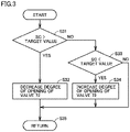
- Fig. 3 is a flowchart for illustrating control of flow rate control valve 72.
- controller 100 increases the degree of opening of flow rate control valve 72 (S34).
- the amount of the liquid refrigerant to be exhausted from receiver 73 increases and the amount of the liquid refrigerant stored in receiver 73 decreases, and thus the amount of the refrigerant circulating through the main refrigerant circuit increases. Accordingly, refrigerant temperature T1 decreases, and thus subcool SC increases.
- controller 100 When subcool SC is equal to the target value (NO in S31 and NO in S33), controller 100 maintains the degree of opening of flow rate control valve 72 in the present state.
- controller 100 controls the degree of opening of flow rate control valve 72 such that refrigerant temperature T1 at the outlet of condenser 20 approaches the target temperature.
- controller 100 feedback-controls flow rate control valve 72 such that refrigerant temperature T1 at the outlet of condenser 20 matches the target temperature, in order to ensure subcool SC of the refrigerant at the outlet of condenser 20, and in a pump down operation, controller 100 closes flow rate control valve 72 to recover the liquid refrigerant to receiver 73.
- the pump down operation is an operation to transfer the refrigerant from load device 3 to outdoor unit 2 and store the refrigerant therein, by placing on-off valve 28 or the like on pipe 85 through which the liquid refrigerant flows in the main refrigerant circuit, and operating compressor 10 with pipe 85 being blocked.
- the pump down operation is performed, for example, by closing first expansion valve 50 or on-off valve 28 before stopping operation, and thereafter operating compressor 10.
- a signal for instructing to start the pump down operation is not transmitted particularly from load device 3 to outdoor unit 2, and the pump down operation is performed in outdoor unit 2 by continuing the normal operation when pressure PL at the low pressure portion detected by pressure sensor 110 decreases to a threshold value PA.
- controller 100 In the pump down operation, when on-off valve 28 is closed and pressure PL at the low pressure portion detected by pressure sensor 110 decreases to a threshold value PB, controller 100 is configured to stop compressor 10 and stop a pump down. Since compressor 10 is configured such that the refrigerant may not pass therethrough when it is stopped, the refrigerant does not flow back to load device 3.
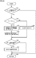
- Fig. 4 is a flowchart for illustrating control during the pump down operation.
- controller 100 determines whether or not pressure PL at the low pressure portion detected by pressure sensor 110 is lower than threshold value PA.
- threshold value PA When PL ⁇ threshold value PA is satisfied (YES in S41), the pump down operation in and after step S42 is performed.
- PL ⁇ threshold value PA is not satisfied (NO in S41), the pump down operation is not performed, and the control is returned to the processing in the normal operation in step S47.
- step S42 controller 100 determines whether or not refrigerant temperature T1 in condenser 20 is lower than TA+ ⁇ .
- ⁇ indicates a temperature difference between the refrigerant and the outside air that may cause a significant reduction in the efficiency of condensing the refrigerant in condenser 20 if the temperature difference becomes further smaller, and is a value determined as appropriate.
- step S43 controller 100 closes flow rate control valve 72. Thereby, the gas refrigerant is exhausted from receiver 73 through degassing pipe 93, and the liquid refrigerant is recovered to receiver 73.
- step S44 controller 100 slightly increases the degree of opening of flow rate control valve 72. Thereby, the liquid refrigerant stored in receiver 73 flows to second passage H2 of heat exchanger 30.
- flow rate control valve 72 is closed, the gas refrigerant flows to second passage H2 of heat exchanger 30 through degassing pipe 93. In the state where the gas refrigerant flows, the coefficient of heat transfer between the heat exchanger and the refrigerant in second passage H2 is low.
- the coefficient of heat transfer between the heat exchanger and the refrigerant in second passage H2 is improved by 10 times or more.
- the refrigerant which has become less condensed in condenser 20 at a stage in which the recovery of the liquid refrigerant has progressed to some extent is condensed in heat exchanger 30, and thus the recovery of the liquid refrigerant can progress.
- the degree of opening of flow rate control valve 72 in step S44 is set to fall within a range in which the amount of the recovered liquid refrigerant in receiver 73 increases.
- controller 100 increases the rotation speed of compressor 10, although controller 100 does not necessarily have to perform this step. This can reduce time for recovering the remaining refrigerant which has become less condensed due to the progress of recovery.
- step S46 controller 100 determines whether or not pressure PL at the low pressure portion detected by pressure sensor 110 decreases to threshold value PB.
- Threshold value PB is a value lower than threshold value PA, and is a determination value for determining that the recovery of the refrigerant in load device 3 is completed. As long as pressure PL does not decrease to threshold value PB (NO in S46), controller 100 continues the operation of compressor 10 and continues the pump down operation.
- step S47 controller 100 stops compressor 10 and terminates the pump down.
- controller 100 closes flow rate control valve 72 to store the liquid refrigerant in receiver 73. Then, at a second time point when the amount of the liquid refrigerant in receiver 73 increases and the efficiency of condenser 20 decreases, controller 100 slightly opens flow rate control valve 72 to improve the efficiency of heat exchanger 30 and promote condensation of the refrigerant in first passage H1. This can reduce time taken to complete the pump down operation.
- the present disclosure relates to outdoor unit 2 of refrigeration cycle apparatus 1, outdoor unit 2 being connectable to load device 3 including first expansion valve 50 corresponding to the "first expansion device” and evaporator 60.
- Outdoor unit 2 includes: first flow path F1 configured to form a circulation flow path through which refrigerant circulates, by being connected to load device 3; compressor 10 and condenser 20 disposed on first flow path F1; second flow path F2 configured to branch from a branch point on first flow path F1 downstream of condenser 20 in a direction in which the refrigerant circulates, and to return, to compressor 10, the refrigerant that has passed through condenser 20; second expansion valve 71 corresponding to the "second expansion device", receiver 73, and flow rate control valve 72 disposed on second flow path F2 in order from the branch point; heat exchanger 30 having first passage H1 and second passage H2 and configured to exchange heat between the refrigerant flowing in first passage H1 and the refrigerant flowing in second passage H2; and controller 100.
- first flow path F1 configured to form a circulation flow path through which refrigerant circulates, by being connected to load device 3
- compressor 10 and condenser 20 disposed on first flow path F1
- First passage H1 of heat exchanger 30 is disposed between condenser 20 and the branch point on first flow path F1.
- Second passage H2 of heat exchanger 30 is disposed between flow rate control valve 72 and compressor 10 on second flow path F2.
- Flow rate control valve 72 is configured to adjust an exhaust flow rate of liquid refrigerant from receiver 73.
- Controller 100 is configured to control compressor 10 and flow rate control valve 72.
- controller 100 When a pump down operation for recovering the refrigerant to receiver 73 is started, controller 100 is configured to control a control state of compressor 10 and flow rate control valve 72, at a first time point, to a first state in which flow rate control valve 72 is closed while compressor 10 is operated.
- controller 100 is configured to transition, at a second time point after the first time point, the control state from the first state to a second state in which flow rate control valve 72 is opened while compressor 10 is operated.
- the amount of the liquid refrigerant in receiver 73 at the second time point is larger than the amount of the liquid refrigerant in receiver 73 at the first time point.
- controller 100 controls the control state of compressor 10 and flow rate control valve 72 to the second state.
- controller 100 controls the control state of compressor 10 and flow rate control valve 72 to the second state.
- controller 100 is configured to set the rotation speed of compressor 10 in the second state to be higher than the rotation speed of compressor 10 in the first state. This can reduce time for recovering the remaining refrigerant which has become less condensed due to the progress of recovery.
- refrigeration cycle apparatus 1 may be utilized in an air conditioner or the like.
- 1 refrigeration cycle apparatus; 2: outdoor unit; 3: load device; 10: compressor; 20: condenser; 22: fan; 28: on-off valve; 30: heat exchanger; 71: second expansion valve; 50: first expansion valve; 60: evaporator; 70: device; 72: flow rate control valve; 73: receiver; 74: flow path switching unit; 80, 81, 82, 83, 84, 85, 88, 89, 91, 92, 94, 96: pipe; 93: degassing pipe; 100: controller; 104: memory; 110, 111: pressure sensor; 120, 121, 122, 123: temperature sensor; F1: first flow path; F2: second flow path; G1: suction port; G2: discharge port; G3: intermediate pressure port; H1: first passage; H2: second passage.
Landscapes
- Engineering & Computer Science (AREA)
- Physics & Mathematics (AREA)
- Mechanical Engineering (AREA)
- Thermal Sciences (AREA)
- General Engineering & Computer Science (AREA)
- Air Conditioning Control Device (AREA)
- Compression-Type Refrigeration Machines With Reversible Cycles (AREA)
Abstract
Description
- The present disclosure relates to an outdoor unit and a refrigeration cycle apparatus.
-
Japanese Patent Laying-Open No. 2014-01917 - PTL 1:
Japanese Patent Laying-Open No. 2014-01917 - A pump down operation is an operation to transfer refrigerant from a load device to an outdoor unit and store the refrigerant therein, by placing an on-off valve or the like on a pipe through which liquid refrigerant flows in a main refrigerant circuit, and operating a compressor with the pipe being blocked.
- In the refrigeration apparatus described in
Japanese Patent Laying-Open No. 2014-01917 - An object of the present disclosure is to provide an outdoor unit and a refrigeration cycle apparatus with reduced refrigerant recovery time during a pump down operation.
- The present disclosure relates to an outdoor unit of a refrigeration cycle apparatus, the outdoor unit being connectable to a load device including a first expansion device and an evaporator. The outdoor unit includes: a first flow path configured to form a circulation flow path through which refrigerant circulates, by being connected to the load device; a compressor and a condenser disposed on the first flow path; a second flow path configured to branch from a branch point on the first flow path downstream of the condenser in a direction in which the refrigerant circulates, and to return, to the compressor, the refrigerant that has passed through the condenser; a second expansion device, a receiver, and a flow rate control valve disposed on the second flow path in order from the branch point; and a heat exchanger having a first passage and a second passage and configured to exchange heat between the refrigerant flowing in the first passage and the refrigerant flowing in the second passage. The first passage of the heat exchanger is disposed between the condenser and the branch point on the first flow path. The second passage of the heat exchanger is disposed between the flow rate control valve and the compressor on the second flow path. The flow rate control valve is configured to adjust an exhaust flow rate of liquid refrigerant from the receiver. When a pump down operation for recovering the refrigerant to the receiver is started, a control state of the compressor and the flow rate control valve is set, at a first time point, to a first state in which the flow rate control valve is closed while the compressor is operated. During the pump down operation, at a second time point after the first time point, the control state transitions from the first state to a second state in which the flow rate control valve is opened while the compressor is operated.
- According to the outdoor unit of the present disclosure, even when refrigerant recovery progresses and a condensation temperature becomes close to an outside air temperature during a pump down operation, the refrigerant is condensed with the efficiency of the heat exchanger being maintained. This can reduce time required for the refrigerant recovery.
-
-
Fig. 1 is an overall configuration diagram of a refrigeration cycle apparatus according to the present embodiment. -
Fig. 2 is a flowchart for illustrating control of asecond expansion valve 71. -
Fig. 3 is a flowchart for illustrating control of a flowrate control valve 72. -
Fig. 4 is a flowchart for illustrating control during a pump down operation. - Hereinafter, embodiments of the present disclosure will be described in detail with reference to the drawings. Although a plurality of embodiments will be described below, it is originally intended from the time of filing the present application to combine features described in the embodiments as appropriate. It should be noted that identical or corresponding parts in the drawings will be designated by the same reference characters, and the description thereof will not be repeated.
-
Fig. 1 is an overall configuration diagram of a refrigeration cycle apparatus according to the present embodiment. It should be noted thatFig. 1 functionally shows the connection relation and the arrangement configuration of devices in the refrigeration cycle apparatus, and does not necessarily show an arrangement in a physical space. - Referring to
Fig. 1 , arefrigeration cycle apparatus 1 includes anoutdoor unit 2, a load device 3, andpipes Outdoor unit 2 has a refrigerant outlet port PO2 and a refrigerant inlet port P12 for connecting to load device 3. Load device 3 has a refrigerant outlet port PO3 and a refrigerant inlet port P13 for connecting tooutdoor unit 2.Pipe 84 connects refrigerant outlet port PO2 ofoutdoor unit 2 to refrigerant inlet port PI3 of load device 3.Pipe 88 connects refrigerant outlet port PO3 of load device 3 to refrigerant inlet port PI2 ofoutdoor unit 2. -
Outdoor unit 2 ofrefrigeration cycle apparatus 1 is connectable to load device 3.Outdoor unit 2 includes acompressor 10 having a suction port G1, a discharge port G2, and an intermediate pressure port G3, acondenser 20, afan 22, aheat exchanger 30, andpipes 80 to 82 and 89.Heat exchanger 30 has a first passage H1 and a second passage H2, and is configured to exchange heat between refrigerant flowing in first passage H1 and the refrigerant flowing in second passage H2. - Load device 3 includes a
first expansion valve 50, anevaporator 60,pipes valve 28.Evaporator 60 is configured to perform heat exchange between air and the refrigerant. Inrefrigeration cycle apparatus 1,evaporator 60 evaporates the refrigerant by absorbing heat from the air in a space to be cooled.First expansion valve 50 is, for example, a temperature expansion valve controlled independently ofoutdoor unit 2. It should be noted thatfirst expansion valve 50 may be an electronic expansion valve which can decompress the refrigerant. On-offvalve 28 is closed when load device 3 stops operation, to block the refrigerant. -
Compressor 10 compresses the refrigerant suctioned frompipe 89, and discharges the compressed refrigerant topipe 80.Compressor 10 can arbitrarily change a drive frequency by inverter control. Further,compressor 10 is provided with intermediate pressure port G3, and allows the refrigerant from intermediate pressure port G3 to flow into an intermediate portion of a compression process.Compressor 10 is configured to adjust a rotation speed according to a control signal from acontroller 100. By adjusting the rotation speed ofcompressor 10, a circulation amount of the refrigerant is adjusted, and the capability ofrefrigeration cycle apparatus 1 can be adjusted. Ascompressor 10, various types of compressors can be adopted, and for example, a compressor of scroll type, rotary type, screw type, or the like can be adopted. -
Condenser 20 is configured such that the high-temperature, high-pressure gas refrigerant discharged fromcompressor 10 performs heat exchange with outside air (heat dissipation). By this heat exchange, the refrigerant is condensed and transforms into a liquid phase. The refrigerant discharged fromcompressor 10 topipe 80 is condensed and liquefied incondenser 20, and flows intopipe 81.Fan 22 for blowing the outside air is attached tocondenser 20 in order to increase the efficiency of heat exchange.Fan 22 supplies condenser 20 with the outside air with which the refrigerant performs heat exchange incondenser 20. By adjusting the number of revolutions offan 22, a refrigerant pressure on a discharge side of compressor 10 (a high pressure-side pressure) can be adjusted. - Here, it is assumed that the refrigerant used for a refrigerant circuit of
refrigeration cycle apparatus 1 is CO2. However, when there occurs a state where a subcool is less likely to be ensured, another refrigerant may be used. - It should be noted that, in the present specification, for ease of description, a device which cools the refrigerant such as CO2 in a supercritical state will also be referred to as
condenser 20. Further, in the present specification, for ease of description, an amount of decrease from a reference temperature of the refrigerant in the supercritical state will also be referred to as a subcool. - A first flow path F1 from refrigerant inlet port PI2 to refrigerant outlet port PO2 via
compressor 10,condenser 20, and first passage H1 ofheat exchanger 30 forms, together with a first flow path F1 on whichfirst expansion valve 50 andevaporator 60 of load device 3 are disposed, a circulation flow path through which the refrigerant circulates. Hereinafter, this circulation flow path will also be referred to as a "main refrigerant circuit" of a refrigeration cycle. -
Outdoor unit 2 further includespipes pipe 96 configured to cause the refrigerant to flow from an outlet of second passage H2 to suction port G1 or intermediate pressure port G3 ofcompressor 10. Hereinafter, a second flow path F2 that branches from the main refrigerant circuit and delivers the refrigerant tocompressor 10 via second passage H2 will also be referred to as an "injection flow path". -
Outdoor unit 2 further includes areceiver 73 disposed on second flow path F2 and configured to store the refrigerant. Asecond expansion valve 71 is disposed betweenpipes pipe 91 branching from the portion of the circulation flow path between the outlet of first passage H1 and refrigerant outlet port PO2, andpipe 92 connected to an inlet ofreceiver 73.Outdoor unit 2 further includes adegassing pipe 93 that connects a gas exhaust outlet ofreceiver 73 to second passage H2 and is configured to exhaust a refrigerant gas withinreceiver 73, athrottle device 70 disposed betweendegassing pipe 93 andpipe 94 leading to second passage H2, and a flowrate control valve 72 configured to adjust a flow rate of the refrigerant inpipe 94 connected to a liquid refrigerant exhaust outlet ofreceiver 73. -
Pipe 91 is a pipe that branches from the main refrigerant circuit and causes the refrigerant to flow intoreceiver 73.Second expansion valve 71 is an electronic expansion valve which can decrease the pressure of the refrigerant at a high pressure portion of the main refrigerant circuit to an intermediate pressure.Receiver 73 is a container in which the refrigerant decompressed and having two phases is separated into a gas phase and a liquid phase, and which can store the refrigerant and adjust the circulation amount of the refrigerant in the main refrigerant circuit. Degassingpipe 93 connected to an upper portion ofreceiver 73 andpipe 94 connected to a lower portion ofreceiver 73 are pipes for taking out the refrigerant separated into gas refrigerant and liquid refrigerant withinreceiver 73, in a separated state. Flowrate control valve 72 adjusts the amount of the liquid refrigerant to be exhausted frompipe 94, and thereby can adjust the amount of the refrigerant inreceiver 73. - By providing
receiver 73 on the injection flow path as described above, it becomes easy to ensure a subcool inpipes 82 and 83 which are liquid pipes. This is because, sincereceiver 73 generally includes the gas refrigerant therein and a refrigerant temperature reaches a saturation temperature, it is not possible to ensure a subcool ifreceiver 73 is disposed onpipe 82. - Further, if
receiver 73 is provided at an intermediate pressure portion, it becomes possible to store the intermediate pressure liquid refrigerant withinreceiver 73 even when the pressure at the high pressure portion of the main refrigerant circuit is high and the refrigerant is in the supercritical state. Thus, the design pressure of the container ofreceiver 73 can be set to be lower than that of the high pressure portion, and cost reduction by thinning the container can also be achieved. -
Outdoor unit 2 further includespressure sensors temperature sensors 120 to 123, andcontroller 100 configured to controlcompressor 10,second expansion valve 71, and flowrate control valve 72. -
Pressure sensor 110 detects a pressure PL at the suction port portion ofcompressor 10, and outputs a detection value thereof tocontroller 100.Pressure sensor 111 detects a discharge pressure PH ofcompressor 10, and outputs a detection value thereof tocontroller 100. -
Temperature sensor 120 detects a discharge temperature TH ofcompressor 10, and outputs a detection value thereof tocontroller 100.Temperature sensor 121 detects a refrigerant temperature T1 inpipe 81 at an outlet ofcondenser 20, and outputs a detection value thereof tocontroller 100.Temperature sensor 122 detects a refrigerant temperature T2 at the outlet of first passage H1 on a cooled side ofheat exchanger 30, and outputs a detection value thereof tocontroller 100.Temperature sensor 123 detects an outside air temperature TA, which is an ambient temperature ofoutdoor unit 2, and outputs a detection value thereof tocontroller 100. - In the present embodiment, second flow path F2 controls discharge temperature TH of
compressor 10 by causing the refrigerant decompressed and having two phases to flow intocompressor 10. In addition, the amount of the refrigerant in the main refrigerant circuit can be adjusted byreceiver 73 placed on second flow path F2. Further, second flow path F2 also ensures supercooling of the refrigerant in the main refrigerant circuit by heat exchange byheat exchanger 30. -
Controller 100 includes a CPU (Central Processing Unit) 102, a memory 104 (a ROM (Read Only Memory) and a RAM (Random Access Memory)), input/output buffers (not shown) for inputting/outputting various signals, and the like.CPU 102 expands programs stored in the ROM onto the RAM or the like and executes the programs. The programs stored in the ROM are programs describing processing procedures ofcontroller 100. According to these programs,controller 100 performs control of the devices inoutdoor unit 2. This control can be processed not only by software but also by dedicated hardware (electronic circuitry). -
Controller 100 feedback-controlssecond expansion valve 71 such that discharge temperature TH ofcompressor 10 matches a target temperature. -
Fig. 2 is a flowchart for illustrating control ofsecond expansion valve 71. When discharge temperature TH ofcompressor 10 is higher than the target temperature (YES in S21),controller 100 increases a degree of opening of second expansion valve 71 (S22). Thereby, the refrigerant flowing into intermediate pressure port G3 viareceiver 73 increases, and thus discharge temperature TH decreases. - On the other hand, when discharge temperature TH of
compressor 10 is lower than the target temperature (NO in S21 and YES in S23),controller 100 decreases the degree of opening of second expansion valve 71 (S24). Thereby, the refrigerant flowing into intermediate pressure port G3 viareceiver 73 decreases, and thus discharge temperature TH increases. - When discharge temperature TH is equal to the target temperature (NO in S21 and NO in S23),
controller 100 maintains the degree of opening ofsecond expansion valve 71 in the present state. - Thus,
controller 100 controls the degree of opening ofsecond expansion valve 71 such that discharge temperature TH ofcompressor 10 approaches the target temperature. - Further, in a normal operation,
controller 100 feedback-controls flowrate control valve 72 such that refrigerant temperature T1 at the outlet ofcondenser 20 matches a target temperature, in order to ensure a subcool SC of the refrigerant at the outlet ofcondenser 20. -
Fig. 3 is a flowchart for illustrating control of flowrate control valve 72. When subcool SC determined by refrigerant temperature T1 at the outlet ofcondenser 20 and a pressure in condenser 20 (approximated by PH) is larger than a target value (YES in S31),controller 100 decreases a degree of opening of flow rate control valve 72 (S32). Thereby, the amount of the liquid refrigerant to be exhausted fromreceiver 73 decreases and the amount of the liquid refrigerant withinreceiver 73 increases, and thus the amount of the refrigerant circulating through the main refrigerant circuit decreases. Accordingly, refrigerant temperature T1 increases, and thus subcool SC decreases. - On the other hand, when subcool SC determined by refrigerant temperature T1 at the outlet of
condenser 20 and the pressure in condenser 20 (approximated by PH) is smaller than the target value (NO in S31 and YES in S33),controller 100 increases the degree of opening of flow rate control valve 72 (S34). Thereby, the amount of the liquid refrigerant to be exhausted fromreceiver 73 increases and the amount of the liquid refrigerant stored inreceiver 73 decreases, and thus the amount of the refrigerant circulating through the main refrigerant circuit increases. Accordingly, refrigerant temperature T1 decreases, and thus subcool SC increases. - When subcool SC is equal to the target value (NO in S31 and NO in S33),
controller 100 maintains the degree of opening of flowrate control valve 72 in the present state. - Thus,
controller 100 controls the degree of opening of flowrate control valve 72 such that refrigerant temperature T1 at the outlet ofcondenser 20 approaches the target temperature. - Further, in the normal operation,
controller 100 feedback-controls flowrate control valve 72 such that refrigerant temperature T1 at the outlet ofcondenser 20 matches the target temperature, in order to ensure subcool SC of the refrigerant at the outlet ofcondenser 20, and in a pump down operation,controller 100 closes flowrate control valve 72 to recover the liquid refrigerant toreceiver 73. - The pump down operation is an operation to transfer the refrigerant from load device 3 to
outdoor unit 2 and store the refrigerant therein, by placing on-offvalve 28 or the like onpipe 85 through which the liquid refrigerant flows in the main refrigerant circuit, and operatingcompressor 10 withpipe 85 being blocked. The pump down operation is performed, for example, by closingfirst expansion valve 50 or on-offvalve 28 before stopping operation, and thereafter operatingcompressor 10. - Generally, a signal for instructing to start the pump down operation is not transmitted particularly from load device 3 to
outdoor unit 2, and the pump down operation is performed inoutdoor unit 2 by continuing the normal operation when pressure PL at the low pressure portion detected bypressure sensor 110 decreases to a threshold value PA. - In the pump down operation, when on-off
valve 28 is closed and pressure PL at the low pressure portion detected bypressure sensor 110 decreases to a threshold value PB,controller 100 is configured to stopcompressor 10 and stop a pump down. Sincecompressor 10 is configured such that the refrigerant may not pass therethrough when it is stopped, the refrigerant does not flow back to load device 3. -
Fig. 4 is a flowchart for illustrating control during the pump down operation. First, in step S41,controller 100 determines whether or not pressure PL at the low pressure portion detected bypressure sensor 110 is lower than threshold value PA. When PL < threshold value PA is satisfied (YES in S41), the pump down operation in and after step S42 is performed. On the other hand, when PL < threshold value PA is not satisfied (NO in S41), the pump down operation is not performed, and the control is returned to the processing in the normal operation in step S47. - In step S42,
controller 100 determines whether or not refrigerant temperature T1 incondenser 20 is lower than TA+α. Here, α indicates a temperature difference between the refrigerant and the outside air that may cause a significant reduction in the efficiency of condensing the refrigerant incondenser 20 if the temperature difference becomes further smaller, and is a value determined as appropriate. - When T1 < TA+α is not satisfied (NO in S42), in step S43,
controller 100 closes flowrate control valve 72. Thereby, the gas refrigerant is exhausted fromreceiver 73 throughdegassing pipe 93, and the liquid refrigerant is recovered toreceiver 73. - On the other hand, when T1 < TA+α is satisfied (YES in S42), in step S44,
controller 100 slightly increases the degree of opening of flowrate control valve 72. Thereby, the liquid refrigerant stored inreceiver 73 flows to second passage H2 ofheat exchanger 30. When flowrate control valve 72 is closed, the gas refrigerant flows to second passage H2 ofheat exchanger 30 throughdegassing pipe 93. In the state where the gas refrigerant flows, the coefficient of heat transfer between the heat exchanger and the refrigerant in second passage H2 is low. - Here, if the liquid refrigerant is mixed by slightly opening flow
rate control valve 72, the coefficient of heat transfer between the heat exchanger and the refrigerant in second passage H2 is improved by 10 times or more. Thereby, the refrigerant which has become less condensed incondenser 20 at a stage in which the recovery of the liquid refrigerant has progressed to some extent is condensed inheat exchanger 30, and thus the recovery of the liquid refrigerant can progress. It should be noted that, since the amount of the recovered liquid refrigerant does not increase if the degree of opening of flowrate control valve 72 is increased too much, the degree of opening of flowrate control valve 72 in step S44 is set to fall within a range in which the amount of the recovered liquid refrigerant inreceiver 73 increases. - Preferably, further in step S37,
controller 100 increases the rotation speed ofcompressor 10, althoughcontroller 100 does not necessarily have to perform this step. This can reduce time for recovering the remaining refrigerant which has become less condensed due to the progress of recovery. - Subsequently, in step S46,
controller 100 determines whether or not pressure PL at the low pressure portion detected bypressure sensor 110 decreases to threshold value PB. Threshold value PB is a value lower than threshold value PA, and is a determination value for determining that the recovery of the refrigerant in load device 3 is completed. As long as pressure PL does not decrease to threshold value PB (NO in S46),controller 100 continues the operation ofcompressor 10 and continues the pump down operation. - On the other hand, when pressure PL decreases to threshold value PB (YES in S46), in step S47,
controller 100 stopscompressor 10 and terminates the pump down. - Through such control, at a first time point when the pump down operation is started,
controller 100 closes flowrate control valve 72 to store the liquid refrigerant inreceiver 73. Then, at a second time point when the amount of the liquid refrigerant inreceiver 73 increases and the efficiency ofcondenser 20 decreases,controller 100 slightly opens flowrate control valve 72 to improve the efficiency ofheat exchanger 30 and promote condensation of the refrigerant in first passage H1. This can reduce time taken to complete the pump down operation. - Finally, the present embodiment will be summarized with reference to the drawings again. As shown in
Fig. 1 , the present disclosure relates tooutdoor unit 2 ofrefrigeration cycle apparatus 1,outdoor unit 2 being connectable to load device 3 includingfirst expansion valve 50 corresponding to the "first expansion device" andevaporator 60.Outdoor unit 2 includes: first flow path F1 configured to form a circulation flow path through which refrigerant circulates, by being connected to load device 3;compressor 10 andcondenser 20 disposed on first flow path F1; second flow path F2 configured to branch from a branch point on first flow path F1 downstream ofcondenser 20 in a direction in which the refrigerant circulates, and to return, tocompressor 10, the refrigerant that has passed throughcondenser 20;second expansion valve 71 corresponding to the "second expansion device",receiver 73, and flowrate control valve 72 disposed on second flow path F2 in order from the branch point;heat exchanger 30 having first passage H1 and second passage H2 and configured to exchange heat between the refrigerant flowing in first passage H1 and the refrigerant flowing in second passage H2; andcontroller 100. - First passage H1 of
heat exchanger 30 is disposed betweencondenser 20 and the branch point on first flow path F1. Second passage H2 ofheat exchanger 30 is disposed between flowrate control valve 72 andcompressor 10 on second flow path F2. Flowrate control valve 72 is configured to adjust an exhaust flow rate of liquid refrigerant fromreceiver 73. -
Controller 100 is configured to controlcompressor 10 and flowrate control valve 72. When a pump down operation for recovering the refrigerant toreceiver 73 is started,controller 100 is configured to control a control state ofcompressor 10 and flowrate control valve 72, at a first time point, to a first state in which flowrate control valve 72 is closed whilecompressor 10 is operated. During the pump down operation,controller 100 is configured to transition, at a second time point after the first time point, the control state from the first state to a second state in which flowrate control valve 72 is opened whilecompressor 10 is operated. - As the pump down operation progresses, recovery of the refrigerant to
receiver 73 progresses, and thus the amount of the liquid refrigerant inreceiver 73 gradually increases. Accordingly, the amount of the liquid refrigerant inreceiver 73 at the second time point is larger than the amount of the liquid refrigerant inreceiver 73 at the first time point. - Preferably, when a difference between an outside air temperature and a condensation temperature of the refrigerant in
condenser 20 becomes smaller than a threshold value,controller 100 controls the control state ofcompressor 10 and flowrate control valve 72 to the second state. Thereby, even when the difference between outside air temperature TA and refrigerant temperature T1 incondenser 20 becomes smaller and the efficiency ofcondenser 20 is reduced at the stage in which the recovery of the liquid refrigerant toreceiver 73 has progressed, it is possible to improve the efficiency ofheat exchanger 30 and further progress the recovery of the liquid refrigerant. - It should be noted that, when the degree of opening of flow
rate control valve 72 in the second state is set to full open for a long time, the amount of the liquid refrigerant inreceiver 73 decreases. Accordingly, in the second state, it is only necessary to open flowrate control valve 72 by a slight degree of opening which may cause an annular flow of the liquid refrigerant in second passage H2 ofheat exchanger 30, or to repeat opening flowrate control valve 72 for a short time and closing flowrate control valve 72. Thereby, the efficiency of heat exchange inheat exchanger 30 is improved, and the refrigerant passing through first passage H1 inheat exchanger 30 is condensed, promoting the recovery of the liquid refrigerant. - More preferably,
controller 100 is configured to set the rotation speed ofcompressor 10 in the second state to be higher than the rotation speed ofcompressor 10 in the first state. This can reduce time for recovering the remaining refrigerant which has become less condensed due to the progress of recovery. - Although the present embodiment has been described by illustrating a refrigerating machine including
refrigeration cycle apparatus 1,refrigeration cycle apparatus 1 may be utilized in an air conditioner or the like. - It should be understood that the embodiment disclosed herein is illustrative and non-restrictive in every respect. The scope of the present disclosure is defined by the scope of the claims, rather than the description of the embodiment described above, and is intended to include any modifications within the scope and meaning equivalent to the scope of the claims.
- 1: refrigeration cycle apparatus; 2: outdoor unit; 3: load device; 10: compressor; 20: condenser; 22: fan; 28: on-off valve; 30: heat exchanger; 71: second expansion valve; 50: first expansion valve; 60: evaporator; 70: device; 72: flow rate control valve; 73: receiver; 74: flow path switching unit; 80, 81, 82, 83, 84, 85, 88, 89, 91, 92, 94, 96: pipe; 93: degassing pipe; 100: controller; 104: memory; 110, 111: pressure sensor; 120, 121, 122, 123: temperature sensor; F1: first flow path; F2: second flow path; G1: suction port; G2: discharge port; G3: intermediate pressure port; H1: first passage; H2: second passage.
Claims (5)
- An outdoor unit of a refrigeration cycle apparatus, the outdoor unit being connectable to a load device including a first expansion device and an evaporator, the outdoor unit comprising:a first flow path configured to form a circulation flow path through which refrigerant circulates, by being connected to the load device;a compressor and a condenser disposed on the first flow path;a second flow path configured to branch from a branch point on the first flow path downstream of the condenser in a direction in which the refrigerant circulates, and to return, to the compressor, the refrigerant that has passed through the condenser;a second expansion device, a receiver, and a flow rate control valve disposed on the second flow path in order from the branch point; anda heat exchanger having a first passage and a second passage and configured to exchange heat between the refrigerant flowing in the first passage and the refrigerant flowing in the second passage, whereinthe first passage of the heat exchanger is disposed between the condenser and the branch point on the first flow path,the second passage of the heat exchanger is disposed between the flow rate control valve and the compressor on the second flow path,the flow rate control valve is configured to adjust an exhaust flow rate of liquid refrigerant from the receiver,when a pump down operation for recovering the refrigerant to the receiver is started, a control state of the compressor and the flow rate control valve is set, at a first time point, to a first state in which the flow rate control valve is closed while the compressor is operated, andduring the pump down operation, at a second time point after the first time point, the control state transitions from the first state to a second state in which the flow rate control valve is opened while the compressor is operated.
- The outdoor unit according to claim 1, wherein, when a difference between an outside air temperature and a condensation temperature of the refrigerant in the condenser becomes smaller than a threshold value, the control state of the compressor and the flow rate control valve is set to the second state.
- The outdoor unit according to claim 2, wherein a rotation speed of the compressor in the second state is higher than a rotation speed of the compressor in the first state.
- The outdoor unit according to claim 1, wherein an amount of the liquid refrigerant in the receiver at the second time point is larger than an amount of the liquid refrigerant in the receiver at the first time point.
- A refrigeration cycle apparatus comprising:the outdoor unit according to any one of claims 1 to 4; andthe load device.
Applications Claiming Priority (1)
| Application Number | Priority Date | Filing Date | Title |
|---|---|---|---|
| PCT/JP2019/035373 WO2021048901A1 (en) | 2019-09-09 | 2019-09-09 | Outdoor unit and refrigeration cycle device |
Publications (3)
| Publication Number | Publication Date |
|---|---|
| EP4030116A1 true EP4030116A1 (en) | 2022-07-20 |
| EP4030116A4 EP4030116A4 (en) | 2022-09-07 |
| EP4030116B1 EP4030116B1 (en) | 2023-10-11 |
Family
ID=74866219
Family Applications (1)
| Application Number | Title | Priority Date | Filing Date |
|---|---|---|---|
| EP19944704.6A Active EP4030116B1 (en) | 2019-09-09 | 2019-09-09 | Outdoor unit and refrigeration cycle device |
Country Status (7)
| Country | Link |
|---|---|
| EP (1) | EP4030116B1 (en) |
| JP (1) | JP7224480B2 (en) |
| CN (1) | CN114341567B (en) |
| DK (1) | DK4030116T3 (en) |
| ES (1) | ES2964488T3 (en) |
| FI (1) | FI4030116T3 (en) |
| WO (1) | WO2021048901A1 (en) |
Cited By (1)
| Publication number | Priority date | Publication date | Assignee | Title |
|---|---|---|---|---|
| EP4411278A4 (en) * | 2021-10-18 | 2025-01-15 | Mitsubishi Heavy Industries Thermal Systems, Ltd. | FREEZING DEVICE |
Families Citing this family (3)
| Publication number | Priority date | Publication date | Assignee | Title |
|---|---|---|---|---|
| CN113294925A (en) * | 2021-05-21 | 2021-08-24 | 浙江国祥股份有限公司 | Evaporative condensation type water chilling unit with combined economizer |
| WO2023199511A1 (en) * | 2022-04-15 | 2023-10-19 | 三菱電機株式会社 | Refrigeration cycle device |
| WO2024023993A1 (en) * | 2022-07-27 | 2024-02-01 | 三菱電機株式会社 | Refrigeration cycle device |
Family Cites Families (10)
| Publication number | Priority date | Publication date | Assignee | Title |
|---|---|---|---|---|
| US5187940A (en) * | 1991-02-19 | 1993-02-23 | Standard Motor Products, Inc. | Refrigerant recovery and purification system |
| JP4734161B2 (en) * | 2006-04-19 | 2011-07-27 | 日立アプライアンス株式会社 | Refrigeration cycle apparatus and air conditioner |
| EP2147264B1 (en) * | 2007-04-24 | 2019-01-16 | Carrier Corporation | Refrigerant vapor compression system |
| JP4687710B2 (en) * | 2007-12-27 | 2011-05-25 | 三菱電機株式会社 | Refrigeration equipment |
| CN201892359U (en) * | 2010-11-30 | 2011-07-06 | 青岛金华工业集团有限公司 | Refrigerant recycling filling machine with two cooling modes |
| JP5500240B2 (en) | 2012-05-23 | 2014-05-21 | ダイキン工業株式会社 | Refrigeration equipment |
| JP6112388B2 (en) | 2012-11-16 | 2017-04-12 | パナソニックIpマネジメント株式会社 | Refrigeration equipment |
| US10168068B2 (en) * | 2013-03-12 | 2019-01-01 | Mitsubishi Electric Corporation | Air-conditioning apparatus |
| JPWO2017175299A1 (en) | 2016-04-05 | 2018-10-25 | 三菱電機株式会社 | Refrigeration cycle equipment |
| JP6935720B2 (en) * | 2017-10-12 | 2021-09-15 | ダイキン工業株式会社 | Refrigeration equipment |
-
2019
- 2019-09-09 FI FIEP19944704.6T patent/FI4030116T3/en active
- 2019-09-09 ES ES19944704T patent/ES2964488T3/en active Active
- 2019-09-09 JP JP2021544990A patent/JP7224480B2/en active Active
- 2019-09-09 EP EP19944704.6A patent/EP4030116B1/en active Active
- 2019-09-09 DK DK19944704.6T patent/DK4030116T3/en active
- 2019-09-09 WO PCT/JP2019/035373 patent/WO2021048901A1/en not_active Ceased
- 2019-09-09 CN CN201980099962.8A patent/CN114341567B/en not_active Expired - Fee Related
Cited By (1)
| Publication number | Priority date | Publication date | Assignee | Title |
|---|---|---|---|---|
| EP4411278A4 (en) * | 2021-10-18 | 2025-01-15 | Mitsubishi Heavy Industries Thermal Systems, Ltd. | FREEZING DEVICE |
Also Published As
| Publication number | Publication date |
|---|---|
| DK4030116T3 (en) | 2023-11-13 |
| JP7224480B2 (en) | 2023-02-17 |
| CN114341567A (en) | 2022-04-12 |
| FI4030116T3 (en) | 2023-11-02 |
| EP4030116B1 (en) | 2023-10-11 |
| WO2021048901A1 (en) | 2021-03-18 |
| ES2964488T3 (en) | 2024-04-08 |
| JPWO2021048901A1 (en) | 2021-03-18 |
| CN114341567B (en) | 2024-01-02 |
| EP4030116A4 (en) | 2022-09-07 |
Similar Documents
| Publication | Publication Date | Title |
|---|---|---|
| EP4030116B1 (en) | Outdoor unit and refrigeration cycle device | |
| EP3954947B1 (en) | Outdoor unit, refrigeration cycle device, and refrigerating machine | |
| US11384965B2 (en) | Refrigeration cycle apparatus performing a refrigerant circulation operation using a liquid pump | |
| US10900695B2 (en) | Refrigeration cycle apparatus | |
| EP3617617B1 (en) | Outdoor unit and method for controlling same | |
| JP7378561B2 (en) | Outdoor unit and refrigeration cycle equipment | |
| EP4030117B1 (en) | Outdoor unit and refrigeration cycle device | |
| EP4130615B1 (en) | Outdoor unit and refrigeration cycle device | |
| EP3614071B1 (en) | Refrigeration cycle device | |
| JP7400857B2 (en) | air conditioner | |
| CN109579332B (en) | Refrigeration system | |
| EP4015939B1 (en) | Refrigeration device | |
| EP4033178A1 (en) | Heat source unit and refrigeration device | |
| US20220146165A1 (en) | Air conditioning apparatus | |
| EP4030122B1 (en) | Outdoor unit and refrigeration cycle apparatus | |
| JP2018119707A (en) | Refrigerant circuit system and control method | |
| JP7381850B2 (en) | Heat source unit and refrigeration equipment | |
| JP7460877B2 (en) | Heat source unit and refrigeration equipment equipped with it | |
| US20250027694A1 (en) | Refrigeration cycle apparatus | |
| WO2024023993A1 (en) | Refrigeration cycle device | |
| JPH02203177A (en) | Refrigerator |
Legal Events
| Date | Code | Title | Description |
|---|---|---|---|
| STAA | Information on the status of an ep patent application or granted ep patent |
Free format text: STATUS: THE INTERNATIONAL PUBLICATION HAS BEEN MADE |
|
| PUAI | Public reference made under article 153(3) epc to a published international application that has entered the european phase |
Free format text: ORIGINAL CODE: 0009012 |
|
| STAA | Information on the status of an ep patent application or granted ep patent |
Free format text: STATUS: REQUEST FOR EXAMINATION WAS MADE |
|
| 17P | Request for examination filed |
Effective date: 20220302 |
|
| AK | Designated contracting states |
Kind code of ref document: A1 Designated state(s): AL AT BE BG CH CY CZ DE DK EE ES FI FR GB GR HR HU IE IS IT LI LT LU LV MC MK MT NL NO PL PT RO RS SE SI SK SM TR |
|
| A4 | Supplementary search report drawn up and despatched |
Effective date: 20220805 |
|
| RIC1 | Information provided on ipc code assigned before grant |
Ipc: F25B 40/00 20060101ALI20220801BHEP Ipc: F25B 1/00 20060101AFI20220801BHEP |
|
| DAV | Request for validation of the european patent (deleted) | ||
| DAX | Request for extension of the european patent (deleted) | ||
| GRAP | Despatch of communication of intention to grant a patent |
Free format text: ORIGINAL CODE: EPIDOSNIGR1 |
|
| STAA | Information on the status of an ep patent application or granted ep patent |
Free format text: STATUS: GRANT OF PATENT IS INTENDED |
|
| INTG | Intention to grant announced |
Effective date: 20230502 |
|
| GRAS | Grant fee paid |
Free format text: ORIGINAL CODE: EPIDOSNIGR3 |
|
| GRAA | (expected) grant |
Free format text: ORIGINAL CODE: 0009210 |
|
| STAA | Information on the status of an ep patent application or granted ep patent |
Free format text: STATUS: THE PATENT HAS BEEN GRANTED |
|
| AK | Designated contracting states |
Kind code of ref document: B1 Designated state(s): AL AT BE BG CH CY CZ DE DK EE ES FI FR GB GR HR HU IE IS IT LI LT LU LV MC MK MT NL NO PL PT RO RS SE SI SK SM TR |
|
| REG | Reference to a national code |
Ref country code: GB Ref legal event code: FG4D |
|
| REG | Reference to a national code |
Ref country code: CH Ref legal event code: EP |
|
| REG | Reference to a national code |
Ref country code: FI Ref legal event code: FGE Ref country code: DE Ref legal event code: R096 Ref document number: 602019039410 Country of ref document: DE |
|
| REG | Reference to a national code |
Ref country code: IE Ref legal event code: FG4D |
|
| REG | Reference to a national code |
Ref country code: DK Ref legal event code: T3 Effective date: 20231107 |
|
| REG | Reference to a national code |
Ref country code: SE Ref legal event code: TRGR |
|
| REG | Reference to a national code |
Ref country code: NO Ref legal event code: T2 Effective date: 20231011 |
|
| REG | Reference to a national code |
Ref country code: LT Ref legal event code: MG9D |
|
| REG | Reference to a national code |
Ref country code: NL Ref legal event code: MP Effective date: 20231011 |
|
| REG | Reference to a national code |
Ref country code: AT Ref legal event code: MK05 Ref document number: 1620581 Country of ref document: AT Kind code of ref document: T Effective date: 20231011 |
|
| PG25 | Lapsed in a contracting state [announced via postgrant information from national office to epo] |
Ref country code: NL Free format text: LAPSE BECAUSE OF FAILURE TO SUBMIT A TRANSLATION OF THE DESCRIPTION OR TO PAY THE FEE WITHIN THE PRESCRIBED TIME-LIMIT Effective date: 20231011 |
|
| PG25 | Lapsed in a contracting state [announced via postgrant information from national office to epo] |
Ref country code: GR Free format text: LAPSE BECAUSE OF FAILURE TO SUBMIT A TRANSLATION OF THE DESCRIPTION OR TO PAY THE FEE WITHIN THE PRESCRIBED TIME-LIMIT Effective date: 20240112 |
|
| REG | Reference to a national code |
Ref country code: ES Ref legal event code: FG2A Ref document number: 2964488 Country of ref document: ES Kind code of ref document: T3 Effective date: 20240408 |
|
| PG25 | Lapsed in a contracting state [announced via postgrant information from national office to epo] |
Ref country code: IS Free format text: LAPSE BECAUSE OF FAILURE TO SUBMIT A TRANSLATION OF THE DESCRIPTION OR TO PAY THE FEE WITHIN THE PRESCRIBED TIME-LIMIT Effective date: 20240211 |
|
| PG25 | Lapsed in a contracting state [announced via postgrant information from national office to epo] |
Ref country code: LT Free format text: LAPSE BECAUSE OF FAILURE TO SUBMIT A TRANSLATION OF THE DESCRIPTION OR TO PAY THE FEE WITHIN THE PRESCRIBED TIME-LIMIT Effective date: 20231011 |
|
| PG25 | Lapsed in a contracting state [announced via postgrant information from national office to epo] |
Ref country code: AT Free format text: LAPSE BECAUSE OF FAILURE TO SUBMIT A TRANSLATION OF THE DESCRIPTION OR TO PAY THE FEE WITHIN THE PRESCRIBED TIME-LIMIT Effective date: 20231011 |
|
| PG25 | Lapsed in a contracting state [announced via postgrant information from national office to epo] |
Ref country code: LT Free format text: LAPSE BECAUSE OF FAILURE TO SUBMIT A TRANSLATION OF THE DESCRIPTION OR TO PAY THE FEE WITHIN THE PRESCRIBED TIME-LIMIT Effective date: 20231011 Ref country code: IS Free format text: LAPSE BECAUSE OF FAILURE TO SUBMIT A TRANSLATION OF THE DESCRIPTION OR TO PAY THE FEE WITHIN THE PRESCRIBED TIME-LIMIT Effective date: 20240211 Ref country code: GR Free format text: LAPSE BECAUSE OF FAILURE TO SUBMIT A TRANSLATION OF THE DESCRIPTION OR TO PAY THE FEE WITHIN THE PRESCRIBED TIME-LIMIT Effective date: 20240112 Ref country code: BG Free format text: LAPSE BECAUSE OF FAILURE TO SUBMIT A TRANSLATION OF THE DESCRIPTION OR TO PAY THE FEE WITHIN THE PRESCRIBED TIME-LIMIT Effective date: 20240111 Ref country code: AT Free format text: LAPSE BECAUSE OF FAILURE TO SUBMIT A TRANSLATION OF THE DESCRIPTION OR TO PAY THE FEE WITHIN THE PRESCRIBED TIME-LIMIT Effective date: 20231011 Ref country code: PT Free format text: LAPSE BECAUSE OF FAILURE TO SUBMIT A TRANSLATION OF THE DESCRIPTION OR TO PAY THE FEE WITHIN THE PRESCRIBED TIME-LIMIT Effective date: 20240212 |
|
| PG25 | Lapsed in a contracting state [announced via postgrant information from national office to epo] |
Ref country code: RS Free format text: LAPSE BECAUSE OF FAILURE TO SUBMIT A TRANSLATION OF THE DESCRIPTION OR TO PAY THE FEE WITHIN THE PRESCRIBED TIME-LIMIT Effective date: 20231011 Ref country code: PL Free format text: LAPSE BECAUSE OF FAILURE TO SUBMIT A TRANSLATION OF THE DESCRIPTION OR TO PAY THE FEE WITHIN THE PRESCRIBED TIME-LIMIT Effective date: 20231011 Ref country code: LV Free format text: LAPSE BECAUSE OF FAILURE TO SUBMIT A TRANSLATION OF THE DESCRIPTION OR TO PAY THE FEE WITHIN THE PRESCRIBED TIME-LIMIT Effective date: 20231011 Ref country code: HR Free format text: LAPSE BECAUSE OF FAILURE TO SUBMIT A TRANSLATION OF THE DESCRIPTION OR TO PAY THE FEE WITHIN THE PRESCRIBED TIME-LIMIT Effective date: 20231011 |
|
| REG | Reference to a national code |
Ref country code: DE Ref legal event code: R097 Ref document number: 602019039410 Country of ref document: DE |
|
| PG25 | Lapsed in a contracting state [announced via postgrant information from national office to epo] |
Ref country code: CZ Free format text: LAPSE BECAUSE OF FAILURE TO SUBMIT A TRANSLATION OF THE DESCRIPTION OR TO PAY THE FEE WITHIN THE PRESCRIBED TIME-LIMIT Effective date: 20231011 |
|
| PG25 | Lapsed in a contracting state [announced via postgrant information from national office to epo] |
Ref country code: SK Free format text: LAPSE BECAUSE OF FAILURE TO SUBMIT A TRANSLATION OF THE DESCRIPTION OR TO PAY THE FEE WITHIN THE PRESCRIBED TIME-LIMIT Effective date: 20231011 |
|
| PG25 | Lapsed in a contracting state [announced via postgrant information from national office to epo] |
Ref country code: SM Free format text: LAPSE BECAUSE OF FAILURE TO SUBMIT A TRANSLATION OF THE DESCRIPTION OR TO PAY THE FEE WITHIN THE PRESCRIBED TIME-LIMIT Effective date: 20231011 Ref country code: SK Free format text: LAPSE BECAUSE OF FAILURE TO SUBMIT A TRANSLATION OF THE DESCRIPTION OR TO PAY THE FEE WITHIN THE PRESCRIBED TIME-LIMIT Effective date: 20231011 Ref country code: RO Free format text: LAPSE BECAUSE OF FAILURE TO SUBMIT A TRANSLATION OF THE DESCRIPTION OR TO PAY THE FEE WITHIN THE PRESCRIBED TIME-LIMIT Effective date: 20231011 Ref country code: EE Free format text: LAPSE BECAUSE OF FAILURE TO SUBMIT A TRANSLATION OF THE DESCRIPTION OR TO PAY THE FEE WITHIN THE PRESCRIBED TIME-LIMIT Effective date: 20231011 Ref country code: CZ Free format text: LAPSE BECAUSE OF FAILURE TO SUBMIT A TRANSLATION OF THE DESCRIPTION OR TO PAY THE FEE WITHIN THE PRESCRIBED TIME-LIMIT Effective date: 20231011 |
|
| PLBE | No opposition filed within time limit |
Free format text: ORIGINAL CODE: 0009261 |
|
| STAA | Information on the status of an ep patent application or granted ep patent |
Free format text: STATUS: NO OPPOSITION FILED WITHIN TIME LIMIT |
|
| P01 | Opt-out of the competence of the unified patent court (upc) registered |
Free format text: CASE NUMBER: APP_42164/2024 Effective date: 20240717 |
|
| 26N | No opposition filed |
Effective date: 20240712 |
|
| PGFP | Annual fee paid to national office [announced via postgrant information from national office to epo] |
Ref country code: FI Payment date: 20240912 Year of fee payment: 6 Ref country code: DE Payment date: 20240730 Year of fee payment: 6 |
|
| PGFP | Annual fee paid to national office [announced via postgrant information from national office to epo] |
Ref country code: DK Payment date: 20240913 Year of fee payment: 6 |
|
| PGFP | Annual fee paid to national office [announced via postgrant information from national office to epo] |
Ref country code: GB Payment date: 20240801 Year of fee payment: 6 |
|
| PGFP | Annual fee paid to national office [announced via postgrant information from national office to epo] |
Ref country code: FR Payment date: 20240808 Year of fee payment: 6 |
|
| PG25 | Lapsed in a contracting state [announced via postgrant information from national office to epo] |
Ref country code: SI Free format text: LAPSE BECAUSE OF FAILURE TO SUBMIT A TRANSLATION OF THE DESCRIPTION OR TO PAY THE FEE WITHIN THE PRESCRIBED TIME-LIMIT Effective date: 20231011 |
|
| PG25 | Lapsed in a contracting state [announced via postgrant information from national office to epo] |
Ref country code: SI Free format text: LAPSE BECAUSE OF FAILURE TO SUBMIT A TRANSLATION OF THE DESCRIPTION OR TO PAY THE FEE WITHIN THE PRESCRIBED TIME-LIMIT Effective date: 20231011 |
|
| PGFP | Annual fee paid to national office [announced via postgrant information from national office to epo] |
Ref country code: NO Payment date: 20240910 Year of fee payment: 6 Ref country code: IT Payment date: 20240812 Year of fee payment: 6 Ref country code: SE Payment date: 20240812 Year of fee payment: 6 |
|
| PGFP | Annual fee paid to national office [announced via postgrant information from national office to epo] |
Ref country code: ES Payment date: 20241001 Year of fee payment: 6 |
|
| PG25 | Lapsed in a contracting state [announced via postgrant information from national office to epo] |
Ref country code: MC Free format text: LAPSE BECAUSE OF FAILURE TO SUBMIT A TRANSLATION OF THE DESCRIPTION OR TO PAY THE FEE WITHIN THE PRESCRIBED TIME-LIMIT Effective date: 20231011 |
|
| REG | Reference to a national code |
Ref country code: CH Ref legal event code: PL |
|
| PG25 | Lapsed in a contracting state [announced via postgrant information from national office to epo] |
Ref country code: LU Free format text: LAPSE BECAUSE OF NON-PAYMENT OF DUE FEES Effective date: 20240909 |
|
| REG | Reference to a national code |
Ref country code: BE Ref legal event code: MM Effective date: 20240930 |
|
| PG25 | Lapsed in a contracting state [announced via postgrant information from national office to epo] |
Ref country code: BE Free format text: LAPSE BECAUSE OF NON-PAYMENT OF DUE FEES Effective date: 20240930 |
|
| PG25 | Lapsed in a contracting state [announced via postgrant information from national office to epo] |
Ref country code: CH Free format text: LAPSE BECAUSE OF NON-PAYMENT OF DUE FEES Effective date: 20240930 |
|
| PG25 | Lapsed in a contracting state [announced via postgrant information from national office to epo] |
Ref country code: IE Free format text: LAPSE BECAUSE OF NON-PAYMENT OF DUE FEES Effective date: 20240909 |
|
| PG25 | Lapsed in a contracting state [announced via postgrant information from national office to epo] |
Ref country code: CY Free format text: LAPSE BECAUSE OF FAILURE TO SUBMIT A TRANSLATION OF THE DESCRIPTION OR TO PAY THE FEE WITHIN THE PRESCRIBED TIME-LIMIT; INVALID AB INITIO Effective date: 20190909 |
|
| PG25 | Lapsed in a contracting state [announced via postgrant information from national office to epo] |
Ref country code: HU Free format text: LAPSE BECAUSE OF FAILURE TO SUBMIT A TRANSLATION OF THE DESCRIPTION OR TO PAY THE FEE WITHIN THE PRESCRIBED TIME-LIMIT; INVALID AB INITIO Effective date: 20190909 |
|
| PG25 | Lapsed in a contracting state [announced via postgrant information from national office to epo] |
Ref country code: FI Free format text: LAPSE BECAUSE OF NON-PAYMENT OF DUE FEES Effective date: 20250909 |
|
| REG | Reference to a national code |
Ref country code: DK Ref legal event code: EBP Effective date: 20250930 |