EP4030088B1 - Kupplung bestimmt für einen druckluftmotor - Google Patents
Kupplung bestimmt für einen druckluftmotor Download PDFInfo
- Publication number
- EP4030088B1 EP4030088B1 EP22151410.2A EP22151410A EP4030088B1 EP 4030088 B1 EP4030088 B1 EP 4030088B1 EP 22151410 A EP22151410 A EP 22151410A EP 4030088 B1 EP4030088 B1 EP 4030088B1
- Authority
- EP
- European Patent Office
- Prior art keywords
- compressed air
- piston
- housing
- channel
- seal
- Prior art date
- Legal status (The legal status is an assumption and is not a legal conclusion. Google has not performed a legal analysis and makes no representation as to the accuracy of the status listed.)
- Active
Links
Images


Classifications
-
- F—MECHANICAL ENGINEERING; LIGHTING; HEATING; WEAPONS; BLASTING
- F16—ENGINEERING ELEMENTS AND UNITS; GENERAL MEASURES FOR PRODUCING AND MAINTAINING EFFECTIVE FUNCTIONING OF MACHINES OR INSTALLATIONS; THERMAL INSULATION IN GENERAL
- F16L—PIPES; JOINTS OR FITTINGS FOR PIPES; SUPPORTS FOR PIPES, CABLES OR PROTECTIVE TUBING; MEANS FOR THERMAL INSULATION IN GENERAL
- F16L29/00—Joints with fluid cut-off means
- F16L29/02—Joints with fluid cut-off means with a cut-off device in one of the two pipe ends, the cut-off device being automatically opened when the coupling is applied
-
- F—MECHANICAL ENGINEERING; LIGHTING; HEATING; WEAPONS; BLASTING
- F16—ENGINEERING ELEMENTS AND UNITS; GENERAL MEASURES FOR PRODUCING AND MAINTAINING EFFECTIVE FUNCTIONING OF MACHINES OR INSTALLATIONS; THERMAL INSULATION IN GENERAL
- F16L—PIPES; JOINTS OR FITTINGS FOR PIPES; SUPPORTS FOR PIPES, CABLES OR PROTECTIVE TUBING; MEANS FOR THERMAL INSULATION IN GENERAL
- F16L37/00—Couplings of the quick-acting type
- F16L37/28—Couplings of the quick-acting type with fluid cut-off means
- F16L37/38—Couplings of the quick-acting type with fluid cut-off means with fluid cut-off means in only one of two pipe-end fittings
- F16L37/40—Couplings of the quick-acting type with fluid cut-off means with fluid cut-off means in only one of two pipe-end fittings with a lift valve being opened automatically when the coupling is applied
- F16L37/42—Couplings of the quick-acting type with fluid cut-off means with fluid cut-off means in only one of two pipe-end fittings with a lift valve being opened automatically when the coupling is applied the valve having an axial bore communicating with lateral apertures
-
- F—MECHANICAL ENGINEERING; LIGHTING; HEATING; WEAPONS; BLASTING
- F16—ENGINEERING ELEMENTS AND UNITS; GENERAL MEASURES FOR PRODUCING AND MAINTAINING EFFECTIVE FUNCTIONING OF MACHINES OR INSTALLATIONS; THERMAL INSULATION IN GENERAL
- F16L—PIPES; JOINTS OR FITTINGS FOR PIPES; SUPPORTS FOR PIPES, CABLES OR PROTECTIVE TUBING; MEANS FOR THERMAL INSULATION IN GENERAL
- F16L19/00—Joints in which sealing surfaces are pressed together by means of a member, e.g. a swivel nut, screwed on, or into, one of the joint parts
- F16L19/02—Pipe ends provided with collars or flanges, integral with the pipe or not, pressed together by a screwed member
- F16L19/0206—Pipe ends provided with collars or flanges, integral with the pipe or not, pressed together by a screwed member the collar not being integral with the pipe
-
- F—MECHANICAL ENGINEERING; LIGHTING; HEATING; WEAPONS; BLASTING
- F16—ENGINEERING ELEMENTS AND UNITS; GENERAL MEASURES FOR PRODUCING AND MAINTAINING EFFECTIVE FUNCTIONING OF MACHINES OR INSTALLATIONS; THERMAL INSULATION IN GENERAL
- F16L—PIPES; JOINTS OR FITTINGS FOR PIPES; SUPPORTS FOR PIPES, CABLES OR PROTECTIVE TUBING; MEANS FOR THERMAL INSULATION IN GENERAL
- F16L37/00—Couplings of the quick-acting type
- F16L37/56—Couplings of the quick-acting type for double-walled or multi-channel pipes or pipe assemblies
- F16L37/565—Concentric pipes
Definitions
- the invention relates to a coupling for connecting a compressed air source to a compressed air motor, comprising a housing with a housing channel leading to a compressed air connection, a piston which is axially adjustable in the housing channel and is subjected to force by a spring element and has an axially extending piston channel, wherein the coupling is designed to pass into a connecting channel leading to the compressed air motor when the coupling is connected to the compressed air motor, wherein the piston can be adjusted in the direction of the compressed air connection by means of a pin element of the compressed air motor against the force applied by the spring element, wherein when there is no interaction between the pin element and the piston, the piston is in a first position due to the force applied by the spring element, in which the housing channel is blocked off from the piston channel via a first seal running between the piston and the housing channel by the first seal resting on a contact surface in the housing channel, and wherein the coupling is further designed such that when the coupling is connected to the compressed air motor, in a second position of the piston there is a
- Pneumatic motors are used, for example, to drive tools. If they are made of stainless steel, they are particularly suitable for the food and chemical industries, as they meet hygienic requirements and work reliably. To clean, such as disinfect, the housing of the pneumatic motors, the connection to the compressed air source must be removed. This is often time-consuming. The same applies if one compressed air supply is to be used for several compressed air motors.
- the DE 1 756 105 U1 is a structurally complex self-closing valve for compressed air lines, which has a spherical valve body with a conical attachment, with a Seal runs.
- the valve body is connected to a sleeve.
- the sleeve is acted upon by a spring element which is supported between a housing part and a shoulder extending from the sleeve.
- the sleeve is guided by sections of housing parts which can be assembled.
- the DE 68 09 307 U1 provides for a compressed air coupling attached to a wall or ceiling, which is connected via a hose to a compressed air tool using a bayonet lock, by means of which a compressed air channel is released.
- a plug-in coupling for compressed air lines is used in the DE 24 43 249 A1 described.
- the present invention is based on the object of providing a coupling for a compressed air motor which enables both rapid release and connection to a compressed air source without causing disadvantages when supplying the compressed air.
- the coupling should be able to be aligned to the desired extent with respect to a compressed air motor, i.e. the coupling should be able to be positioned in a movable manner.
- Another aspect is that it should be possible to direct the exhaust air away in a targeted manner.
- the invention essentially provides that a distance between the contact area of the first seal on the contact surface and the second seal is determined such that when the first seal rests on the contact surface, an abutment surface between the piston and the pin element runs between the contact surface and the second seal.
- the invention is characterized characterized in that the piston has a first section running on the compressed air motor side and a second section running on the compressed air connection side, that the first section has a cylindrical geometry on the outside and the piston channel runs within it, that the second section has a larger cross-section than the first section and runs at a distance from the inner surface of the housing channel, that the spring element is supported on the one hand on the compressed air connection side, preferably on the compressed air connection, and on the other hand on the second section, that a first seal runs in the second section or in the transition area between the first and the second section, that the housing channel has a contact surface, that the first seal rests on the contact surface when there is no interaction between the pin element and the piston, and that the piston channel has radially running openings in its compressed air connection side area, which run in relation to the contact surface in such a way that when the seal does not rest on the contact surface there is a connection between the housing channel and the piston channel, and when the seal rests on the contact surface the connection is blocked.
- a coupling which can be connected to a compressed air motor, wherein the housing of the coupling has a compressed air connection and a piston is adjustable within the housing, which in a first position in which the housing, i.e. the coupling, is detached from the motor connection, blocks compressed air present in the housing, and in a second position in which there is a connection to the compressed air motor, the compressed air can flow to the compressed air motor.
- the housing has at least one, preferably two connections running in the longitudinal axis direction, such as channels or holes in the Housing wall, via which the exhaust air from the compressed air motor is led away.
- the air is led away via a hose which, for example, has a length of more than two, preferably more than three meters, and is connected to a silencer in order to achieve noise reduction.
- the first seal which originates in particular from the piston, either rests against a contact surface formed in the inner surface of the housing or is spaced apart from it. In this area, the piston runs at a distance from the inner surface of the housing, so to speak, an annular space is formed to allow compressed air to flow to the required extent.
- the spring element acts on the front area of the piston on the compressed air connection side results in a simple construction, in particular the spring element is easy to insert and replace.
- the housing does not have to be disassembled. Instead, it is only necessary to detach the air pressure connection from the housing.
- the contact surface has a conical shape, i.e. the geometry of a cone.
- the piston consists of a first section running on the compressed air motor side with a cylinder geometry and a second section running on the compressed air connection side, which is expanded compared to the first section, i.e. has an effective cross-section that is larger than that of the first section.
- the first seal can start from the second section.
- the first seal runs in the transition area between the first and second sections, in particular in a groove via which the first section merges into the second section.
- the second section preferably has a T-geometry in longitudinal section with a cross leg, on the surface of which on the compressed air connection side the spring element is supported with one of its ends.
- the other end of the spring element which is in particular a helical spring, should be supported on the inner surface of the compressed air connection connected to the housing.
- the spring element surrounds the longitudinal leg of the second section of the piston, which, as mentioned, preferably has a T-geometry in longitudinal section.
- the invention provides that the second seal runs parallel to the first seal in the inner surface of the housing, via which the pin element can be sealed against the housing, wherein the distance of the contact surface for the first seal, specifically in the area on which the first seal rests when the coupling is locked, from the second seal is set in such a way that when the first seal rests on the contact surface, the impact surface between the piston and the pin element runs between the contact surface, i.e. the contact area of the first seal on the contact surface, and the second seal. This ensures that when the coupling is open, i.e.
- a third seal is provided which creates a seal between the outer surface of the housing and the section of the pneumatic motor which accommodates the coupling.
- the invention is particularly characterized by the fact that in the housing, ie its wall, at least one exhaust air connection to an exhaust air opening of the compressed air motor.
- This at least one exhaust air connection opens into a first hose that is connected to the housing of the coupling.
- a second hose runs inside the first hose and leads to the compressed air connection.
- the invention also relates to a pneumatic motor with a clutch, with one or more of the features explained above.
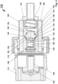
- a coupling 10 which can be referred to as a quick coupling, is connected to a section 12 of a pneumatic motor via a union nut 14, as is self-explanatory.
- the coupling 10 has a housing 16 with a pin-shaped connection 18 that can be connected to it for a connecting element generally referred to as a hose, which leads to a compressed air source in order to supply the compressed air motor with
- the connection 18 extends centrally from the front area 20 of the housing 16, which can also be referred to as the distal area in relation to the compressed air motor.
- connection 18 opens into an interior space 22 of the housing 16, which can be referred to as a housing channel, in which a piston 24 is adjustable in the longitudinal axis direction of the housing 16, which piston is subjected to force in the direction of the proximal region of the housing 16, i.e. the region of the connection with the pneumatic motor, by means of a spring, such as a coil spring 26.
- a spring such as a coil spring 26.
- the piston 24 runs with a pressure connection-side section at a distance from the inner wall 28 of the interior 22, so that an annular space 30 is present in which the compressed air is present or through which the compressed air can flow.
- the adjoining section of the piston 24, which runs on the compressed air motor connection side, is guided axially in the housing 16, as is also self-explanatory to see from the figures.
- the piston 24 has, in its region 30 close to the pneumatic motor, a central recess, such as bore 32, which can also be referred to as a piston channel, from which radially extending openings 34, 36 extend, which penetrate the piston 24 peripherally, as is also self-explanatory from the drawing.
- a central recess such as bore 32, which can also be referred to as a piston channel, from which radially extending openings 34, 36 extend, which penetrate the piston 24 peripherally, as is also self-explanatory from the drawing.
- the piston 24 is sealed against the inner wall 28 by at least one circumferential seal 38, which, depending on the position of the piston 24, either blocks a connection between the openings 34, 36 and the annular space 30 ( Fig.2 ) or releases ( Fig.1 ).
- the latter is the case when the coupling 10 is connected to the pneumatic motor 12 by means of the union nut 14 and the piston 24 is adjusted in the direction of the distal area, i.e. the front area 20, of the housing 16, against the spring force and the compressed air acting on it.
- a pressure element such as a pin element or pin 40, extends from the pneumatic motor 12, which extends in or through the connection 15 of the pneumatic motor 12, onto which the union nut 14 is screwed, in such a way that when the coupling 10 is connected to the pneumatic motor 12, the pressure element or the pin 40 interacts with the motor-side front area 33 of the piston 24 in such a way that it is adjusted in the direction of the distal area of the housing 16, i.e.
- the spring 26 is compressed, as can be seen from the Fig.1 In this second position, the openings 34, 36 are connected to the annular space 30, so that compressed air can flow via the openings 34, 36 and 41, the bore 32 in the piston 24 and an axially extending recess such as a bore in the pressure element 40, which merges into this and is connected to the compressed air motor for its actuation.
- the bore 41 can also be referred to as a connecting channel.
- pressure element or pin 40 is to be understood as a synonym for corresponding possible solutions.
- the force acting on the piston 24 causes it to be displaced in the housing 16 such that the openings 34, 36 are located between the proximal region of the housing 16 and the seal 38, in the so-called first position, so that the connection to the annular space 30 is blocked and thus compressed air can no longer flow through the bore 32 in the direction of the compressed air motor 12.
- the housing 16 there are two channels or bores 42, 44 running in the longitudinal direction of the housing 16, which are connected to or merge into exhaust air bores 46, 48 of the pneumatic motor 12 when the coupling 10 is connected to it.
- the channels 42, 44 pass through the front surface area of the housing 16 so that when the peripheral wall 50 of the housing 16 is surrounded by a hose, the exhaust air can be discharged.
- the corresponding hose initially coaxially surrounds the hose connected to the compressed air source and extending from the pin section 18.
- the hose carrying the exhaust air can be connected to a silencer in order to reduce the noise level.
- the coupling 10 is preferably made of stainless material such as steel, so that hygiene requirements can also be met in this respect.
- Another seal is located between the union nut 14 and the housing 16 of the coupling 10.
- a seal also runs between the pressure element 40 and the inner wall 28 of the housing 16.
- a coupling 110 corresponding to the invention can be seen, which can be used in particular for a pneumatic motor in the food industry, without this being a restriction of the teaching of the invention.
- the coupling 110 - like the coupling 10 - is not tied to a specific location, so that a connection to pneumatic motors that are operated by hand, for example, can be made without any problem.
- a direct connection of the coupling to an air motor or a section 112 of the air motor a direct connection of the coupling to an air motor or a section 112 of the air motor.
- a union nut 114 is provided which receives the section 112 and extends from the coupling 100, as the drawings illustrate.
- a compressed air connection 118 can be connected to the housing 116 of the coupling 110, which in particular passes through the front side 120 of the housing 116 and can be screwed into it.
- the housing 116 is designed in such a way that an interior space is created, which can be referred to as a housing channel 122, via which compressed air can flow in a similar manner via the connection 118 through the coupling 110 to the compressed air motor.
- a piston 124 is adjustable within the housing channel 122 and in the axial direction, which is subjected to force by means of a spring element 126, preferably designed as a helical spring, towards the proximal region of the coupling 110, i.e. in the direction of the region in which the pneumatic motor or the section 112 is connected to the coupling 110.
- the opposite front region 120 is to be referred to as the distal region of the coupling 110.
- the piston 124 consists of a first section 126 with a cylindrical geometry and a second section 128 which has a T-geometry in longitudinal section.
- the piston channel 130 In the first section 126 there is a central bore which is referred to as the piston channel 130. which in its base area merges into radially extending openings 134, 136 which penetrate the piston wall in order to allow compressed air to flow, depending on the position of the piston 124, either via the connection 118, the housing channel 122 and the piston channel 130 to a connecting channel 138 running in the section 112 for actuating the pneumatic motor, which runs within a hollow pin - also called a pin element 140 - or to shut off the compressed air ( Fig.4 ) when the coupling 110 is separated from the pneumatic motor.
- a first seal 142 is provided, which runs in the transition region between the first section 126 and the second section 128 of the piston 124, specifically in a groove 144.
- the first seal 142 rests against the proximal outer surface 146 of the cross leg 148 of the second section 128 of the piston 124.
- the spring 126 rests at one end on the opposite distal outer surface 150 of the cross leg 146. The opposite end rests on the inside of the compressed air connection 118 that can be screwed into the housing 116.
- the first seal 142 is assigned a contact surface 152 in the inner wall of the housing 116 of the coupling 110, against which the first seal 142 rests when the compressed air flow is to be shut off, i.e. when the compressed air motor is separated from the coupling 110.
- the spring 126 acts on the piston 124 in such a way that it is adjusted in the direction of the area on the compressed air motor connection side to such an extent that the first seal 142 rests sealingly on the contact surface 152. Since the radially extending openings 134, 136 of the piston 124 are located between the proximal area of the housing 116, i.e. the end face on the compressed air motor side, and the contact surface 142 when the first seal 142 rests on the contact surface 152, compressed air cannot flow through the openings 134, 136.
- the pin 140 acts with its front face on the facing front face of the first section 126 of the piston 124 with the result that when the piston 124 is axially adjusted - by turning the union nut 114 - in the direction of the compressed air connection 118, the force caused by the spring 126 is overcome and thus the first seal 142 is spaced from the contact surface 152.
- the radially extending openings 134, 136 reach the area of the housing channel 122, in which the contact surface 142, which has a conical geometry, runs with the result that compressed air can flow via the housing channel 130 and the openings 134, 136 into the connecting channel 138 and thus to the pneumatic motor.
- the connecting channel 138 runs in the pin 140, which can also be referred to as a sleeve.
- the contact surface between the pin 140 and the first section 126 of the piston 124 is in Fig.3 marked with the reference number 154.
- a second seal 156 is embedded in the inner wall of the housing 116, by means of which the housing 116 is sealed against the pin 140 until the first seal 142 seals against the contact surface 152. Accordingly, the distance between the second seal 156 and the contact surface 152 is coordinated with respect to the length of the piston 124 and thus the abutment surface 154 with respect to the distance between the first seal 142 and the abutment surface 154.
- a third seal 157 seals the section 122 from the housing 116, which is preferably embedded in the housing wall.
- Exhaust air ducts 160, 162 run inside the housing wall, through which air returned from the compressed air motor can flow.
- the exhaust air is guided away by a hose element 164 that surrounds the housing 116.
- Inside the corresponding hose 164 runs a hose 166 connected to the compressed air connection 118.
- Couplings 10 and 110 are therefore available, which allow compressed air to be supplied and exhausted.
- the noise level when using the compressed air motor is reduced at the same time, especially if the exhaust air is led away via a hose, e.g. 3 metres long, and then passes through a silencer.
- the first hose element 164 i.e. the hose through which the exhaust air is led away, opens into a housing that is made in particular of plastic.
- the supply air hose 166 which carries the compressed air, is led through the middle of the housing and sealed with an O-ring.
- the exhaust air emerging from the exhaust air hose can escape via silencers that are installed in or on the housing.
- the invention relates to a coupling 10, 110 for connecting a compressed air source to a compressed air motor, comprising a housing 16, 116 with a housing channel leading to a compressed air connection 18, 118, a piston 24, 124 which is axially adjustable in the housing channel 22, 122 and is acted upon by a spring element 26, 126 and has an axially extending piston channel 30, 132 which, when the coupling is connected to the compressed air motor, merges into a connecting channel 41, 138 present in a pin element 40, 140 of the compressed air motor, wherein the piston can be adjusted in the direction of the compressed air connection by means of the pin element against the force applied by the spring element, wherein, in the absence of interaction between the pin element and the piston, the piston is in a first position due to the force applied by the spring element, in which the housing channel is offset relative to the piston channel via a extending first seal 38, 142 is blocked off, and when the coupling is connected to the compressed air motor in a second position of the piston there is a compressed air connection between the
- the invention relates to a coupling 10, 110 for connecting a compressed air source to a compressed air motor, comprising a housing 16, 116 with a housing channel leading to a compressed air connection 18, 118, a piston 24, 124 which is axially adjustable in the housing channel 22, 122 and is acted upon by a spring element 26, 126 and has an axially extending piston channel 30, 132 which, when the coupling is connected to the compressed air motor, merges into a connecting channel 41, 138 present in a pin element 40, 140 of the compressed air motor, wherein the piston is displaced in the direction of the compressed air connection is adjustable by means of the pin element, wherein in the absence of interaction between the pin element and the piston, the piston is in a first position due to the application of force by the spring element, in which the housing channel is blocked off from the piston channel via a first seal 38, 142 running between the piston and the housing channel, and when the coupling is connected to the compressed air motor, in a second position of the piston there is a compressed air connection between the
- the invention provides in particular that the contact surface 152 has a conical shape.
- first section 126 merges via a groove 144 into the second section 128 in which the first seal 142 runs.
- the invention is also characterized in that the second section 128 has a T-shape in longitudinal section with a transverse leg 148, wherein the spring element, such as a helical spring, is preferably attached on the one hand to the compressed air connection side 146 of the cross leg and on the other hand on the inner surface of the compressed air connection 118 connected to the housing 116.
- the spring element such as a helical spring
- the housing channel 122 has on its inside a circumferential second seal 156 running parallel to the first seal 142, via which the pin element 140 can be sealed against the housing channel 122, wherein the distance between the contact area of the first seal on the contact surface 152 and the second seal is set such that when the first seal rests on the contact surface, the abutment surface 154 between the piston 124 and the pin element runs between the contact surface and the second seal.
- the invention is also characterized in that in the wall of the housing 116 at least one exhaust air connection 160, 162, such as a channel or bore, extending from the compressed air motor runs through the compressed air connection-side region of the wall, in particular its front side 120.
- at least one exhaust air connection 160, 162 such as a channel or bore, extending from the compressed air motor runs through the compressed air connection-side region of the wall, in particular its front side 120.
- the invention is further characterized in that the housing 16, 116 is connected to a first hose element 164 into which the at least one exhaust air connection opens.
- the invention is characterized in that the compressed air connection 18, 118 extends from the front region of the housing 16, 116 remote from the compressed air motor connection, which is designed such that a second hose element 166 can be connected to it, which is partially surrounded by the first hose element 164.
- first hose element 164 is designed or connected to a device in order to be connected to a silencer.
- the first hose element 164 has a length of at least 200 cm, preferably at least 300 cm.
- the first hose element 164 opens into a housing, preferably made of plastic.
- the drain exits the first hose element 164 and then passes through silencers that are attached to or in the housing. This results in a significant reduction in noise.
- the hose 166 supplying the compressed air is guided through the housing and sealed against it using, for example, an O-ring. This makes it easy to route the compressed air hose 166 and the exhaust air hose 164 coaxially.
- the invention provides that the coupling 10, 110 is not arranged in a fixed location, but can be connected to a compressed air motor at a desired location.
- the invention is also characterized by a pneumatic motor with a clutch which is characterized by at least some of the features described above.
Landscapes
- Engineering & Computer Science (AREA)
- General Engineering & Computer Science (AREA)
- Mechanical Engineering (AREA)
- Compressor (AREA)
- Hydraulic Clutches, Magnetic Clutches, Fluid Clutches, And Fluid Joints (AREA)
Description
- Die Erfindung bezieht sich auf eine Kupplung zum Verbinden einer Druckluftquelle mit einem Druckluftmotor, umfassend ein Gehäuse mit einem zu einem Druckluftanschluss führenden Gehäusekanal, einen axial in dem Gehäusekanal verstellbaren von einem Federelement kraftbeaufschlagten Kolben mit einem axial verlaufenden Kolbenkanal, wobei die Kupplung ausgebildet ist, um bei mit dem Druckluftmotor verbundener Kupplung in einen zu dem Druckluftmotor führenden Verbindungskanal überzugehen, wobei der Kolben entgegen der Kraftbeaufschlagung durch das Federelement in Richtung des Druckluftanschlusses mittels eines Zapfelements des Druckluftmotors verstellbar ist, wobei bei fehlendem Wechselwirken zwischen dem Zapfenelement und dem Kolben sich der Kolben in einer ersten Stellung durch die Kraftbeaufschlagung durch das Federelement befindet, in der der Gehäusekanal gegenüber dem Kolbenkanal über eine zwischen dem Kolben und dem Gehäusekanal verlaufende erste Dichtung durch Anliegen der ersten Dichtung an einer Anlagefläche in dem Gehäusekanal abgesperrt ist, und wobei die Kupplung des Weiteren derart ausgebildet ist, dass bei mit dem Druckluftmotor verbundener Kupplung in einer zweiten Stellung des Kolbens eine Druckluftverbindung zwischen dem Gehäusekanal, dem Kolbenkanal und dem Verbindungskanal besteht, wobei das Federelement zwischen dem Druckluftanschluss und druckluftanschlussseitigem Bereich des Kolbens verläuft, wobei von dem druckluftanschlussseitigen Bereich des Kolbenkanals radial verlaufende Öffnungen ausgehen, über die in der zweiten Stellung des Kolbens die Druckluft strömt, und wobei in der Wandung des Gehäuses zumindest ein Abluftkanal verläuft, der die Wandung in ihrem druckluftanschlussseitigen Bereich durchsetzt, wobei die Kupplung derart ausgebildet ist, dass der Abluftkanal mit dem Druckluftmotor verbindbar ist, wobei der Kolben mittels des den Verbindungskanal aufweisenden Zapfenelements des Druckluftmotors verstellbar ist, der Gehäusekanal in seiner Innenseite eine parallel zu der ersten Dichtung verlaufende umlaufende zweite Dichtung aufweist, über die das Zapfenelement gegenüber dem Gehäusekanal abdichtbar ist.
- Druckluftmotoren werden z.B. zum Antrieb von Werkzeugen eingesetzt. Bestehen diese aus rostfreiem Stahl, so ist insbesondere eine Eignung in der Nahrungsmittel- und chemischen Industrie gegeben, da diese hygienischen Anforderungen genügen und zuverlässig arbeiten. Zum Reinigen, wie z.B. Desinfizieren, des Gehäuses entsprechender Druckluftmotoren muss die Verbindung zur Druckluftquelle entfernt werden. Dies ist häufig zeitaufwendig. Gleiches gilt für den Fall, wenn eine Druckluftzuführung für mehrere Druckluftmotoren benutzt werden soll.
- Der
DE 1 756 105 U1 ist ein konstruktiv aufwendiges Selbstschlussventil für Druckluftleitungen zu entnehmen, das einen kugelförmigen Ventilkörper mit konusförmigem Ansatz aufweist, wobei zwischen dem Ansatz und dem Körper eine Dichtung verläuft. Der Ventilkörper ist mit einer Hülse verbunden. Auf die Hülse wirkt ein Federelement, das sich zwischen einem Gehäuseteil und einer von der Hülse ausgehenden Schulter abstützt. Die Führung der Hülse erfolgt über zusammensetzbare Abschnitte von Gehäuseteilen. - Die
DE 68 09 307 U1 sieht eine an einer Wandung oder einer Decke befestigte Druckluftkupplung vor, die über einen Schlauch mit einem Druckluftwerkzeug unter Verwendung eines Bajonettverschlusses verbunden wird, mittels dessen ein Druckluftkanal freigegeben wird. - Der
US 2020/0132233 A1 ist eine Stecker-Schlauch-Verbindung zu entnehmen, um eine Nagelpistole betreiben zu können. - Um einen Schlauch mit einem Ventil zu verbinden, wird nach der
US 2,628,850 A eine Kupplung vorgeschlagen, die dann ein Fluid absperrt, wenn die Kupplung von dem Ventil gelöst ist. - Eine Steckkupplung für Druckluftleitungen wird in der
DE 24 43 249 A1 beschrieben. - Der
US 9,528,650 B2 - Der vorliegenden Erfindung liegt die Aufgabe zugrunde, eine Kupplung für einen Druckluftmotor zur Verfügung zu stellen, die sowohl ein schnelles Lösen als auch ein Verbinden mit einer Druckluftquelle ermöglicht, ohne dass sich Nachteile beim Zuführen der Druckluft ergeben. Dabei soll die Kupplung im gewünschten Umfang zu einem Druckluftmotor ausrichtbar, also die Kupplung ortsveränderlich positionierbar sein.
- Nach einem weiteren Aspekt soll die Möglichkeit gegeben sein, die Abluft gezielt wegzuführen.
- Auch soll die Möglichkeit eröffnet sein, eine Reduzierung des Schallpegels zu erreichen, der bei Druckluftmotoren recht hoch ist.
- Zur Lösung der Aufgabe sieht die Erfindung im Wesentlichen vor, dass ein Abstand zwischen dem Kontaktbereich der ersten Dichtung auf der Anlagefläche zu der zweiten Dichtung derart festgelegt ist, dass beim Anliegen der ersten Dichtung an der Anlagefläche eine Stoßfläche zwischen dem Kolben und dem Zapfenelement zwischen der Anlagefläche und der zweiten Dichtung verläuft.
- Insbesondere zeichnet sich die Erfindung dadurch aus, dass der Kolben einen druckluftmotorseitig verlaufenden ersten Abschnitt und einen druckluftanschlussseitig verlaufenden zweiten Abschnitt aufweist, dass der erste Abschnitt außenseitig eine Zylindergeometrie aufweist und innerhalb von diesem der Kolbenkanal verläuft, dass der zweite Abschnitt im Vergleich zu dem ersten Abschnitt einen größeren Querschnitt aufweist und beabstandet zur Innenfläche des Gehäusekanals verläuft, dass das Federelement zum einen druckluftranschlussseitig, vorzugsweise an dem Druckluftanschluss, und zum anderen an dem zweiten Abschnitt abgestützt ist, dass im zweiten Abschnitt oder im Übergangsbereich zwischen dem ersten und dem zweiten Abschnitt eine erste Dichtung verläuft, dass der Gehäusekanal eine Anlagefläche aufweist, dass die erste Dichtung bei fehlendem Wechselwirken zwischen dem Zapfenelement und dem Kolben an der Anlagefläche anliegt, und dass der Kolbenkanal in seinem druckluftanschlussseitigen Bereich radial verlaufende Öffnungen aufweist, die derart in Bezug auf die Anlagefläche verlaufen, dass bei fehlendem Anliegen der Dichtung an der Anlagefläche eine Verbindung zwischen dem Gehäusekanal und dem Kolbenkanal besteht, und beim Anliegen der Dichtung an der Anlagefläche die Verbindung gesperrt ist.
- Erfindungsgemäß wird eine Kupplung vorgeschlagen, die mit einem Druckluftmotor verbindbar ist, wobei das Gehäuse der Kupplung einen Druckluftanschluss aufweist und innerhalb des Gehäuses ein Kolben verstellbar ist, der in einer ersten Stellung, in der das Gehäuse, also die Kupplung von dem Motoranschluss gelöst ist, in dem Gehäuse anstehende Druckluft absperrt, und in einer zweiten Stellung, in der eine Verbindung zu dem Druckluftmotor besteht, die Druckluft zu dem Druckluftmotor strömen kann.
- Dabei ist insbesondere vorgesehen, dass das Gehäuse zumindest eine, vorzugsweise zwei in Längsachsenrichtung verlaufende Verbindungen, wie Kanäle oder Bohrungen in der Gehäusewandung, aufweist, über die von dem Druckluftmotor stammende Abluft weggeführt wird. Bevorzugterweise erfolgt das Wegführen über einen Schlauch, der z.B. eine Länge von mehr als zwei, vorzugsweise von mehr als drei Meter aufweist, mit einem Schalldämpfer verbunden ist, um eine Geräuschreduzierung zu erzielen. Hierdurch ergibt sich der Vorteil, dass die von dem Druckluftmotor stammende Abluft nicht unmittelbar im Bereich des Druckluftmotors ausströmt, wodurch eine unerwünschte Geräuschbildung auftreten würde.
- Um wahlweise die Druckluft abzusperren oder diese mit dem Druckluftmotor zu verbinden, liegt die insbesondere von dem Kolben ausgehende erste Dichtung entweder an einer in der Innenfläche des Gehäuses ausgebildeten Anlagefläche an oder ist zu dieser beabstandet. In diesem Bereich verläuft der Kolben beabstandet zur Innenfläche des Gehäuses, quasi ein Ringraum wird ausgebildet, um im erforderlichen Umfang Druckluft strömen zu lassen.
- Dadurch, dass das Federelement auf den druckluftanschlussseitigen Stirnbereich des Kolbens einwirkt, ergibt sich eine einfache Konstruktion, insbesondere ein einfaches Einsetzen und Austauschen des Federelements. Das Gehäuse muss nicht auseinandergenommen werden. Vielmehr ist es nur erforderlich, den Luftdruckanschluss von dem Gehäuse zu lösen.
- Insbesondere ist vorgesehen, dass die Anlagefläche eine Konusform, also die Geometrie eines Kegels aufweist.
- Ferner ist besonders hervorzuheben, dass der Kolben aus einem druckluftmotorseitig verlaufenden ersten Abschnitt mit einer Zylindergeometrie und einem druckluftanschlussseitig verlaufenden zweiten Abschnitt besteht, der gegenüber dem ersten Abschnitt erweitert ist, also einen wirksamen Querschnitt aufweist, der größer als der des ersten Abschnitts ist.
- Die erste Dichtung kann von dem zweiten Abschnitt ausgehen. Insbesondere ist jedoch vorgesehen, dass die erste Dichtung im Übergangsbereich zwischen dem ersten und dem zweiten Abschnitt verläuft, insbesondere in einer Nut, über die der erste Abschnitt in den zweiten Abschnitt übergeht.
- Hervorzuheben ist des Weiteren, dass der zweite Abschnitt im Längsschnitt vorzugsweise eine T-Geometrie mit einem Querschenkel aufweist, an dessen druckluftanschlussseitiger Fläche das Federelement mit einer seiner Enden abgestützt ist. Das andere Ende des Federelementes, bei dem es sich insbesondere um eine Schraubenfeder handelt, sollte an der Innenfläche des mit dem Gehäuse verbundenen Druckluftanschlusses abgestützt sein.
- Zur sicheren Fixierung des Federelementes umgibt dieses den Längsschenkel des zweiten Abschnitts des Kolbens, der erwähntermaßen bevorzugterweise im Längsschnitt eine T-Geometrie aufweist.
- Um auszuschließen, dass Druckluft zwischen Zapfenelement und Kupplung bzw. deren Innenseite entweichen kann, sieht die Erfindung vor, dass parallel zur ersten Dichtung in der Innenfläche des Gehäuses die zweite Dichtung verläuft, über die das Zapfenelement gegenüber dem Gehäuse abdichtbar ist, wobei der Abstand der Anlagefläche für die erste Dichtung, und zwar in dem Bereich, auf dem die erste Dichtung bei sperrender Kupplung aufliegt, zu der zweiten Dichtung derart festgelegt ist, dass beim Anliegen der ersten Dichtung an der Anlagefläche die Stoßfläche zwischen dem Kolben und dem Zapfenelement zwischen der Anlagefläche, d.h. dem Kontaktbereich der ersten Dichtung auf der Anlagefläche, und der zweiten Dichtung verläuft. Somit ist sichergestellt, dass bei geöffneter Kupplung, also dann, wenn mittels des Zapfenelementes der Kolben entgegen der von dem Federelement hervorgerufenen Kraft in Richtung des Druckluftanschlusses verstellt wird, um die erste Dichtung zu der Anlagefläche zu beabstanden, Falschluft nicht austreten kann. Die Abdichtung der zweiten Dichtung wirkt stets, bis die erste Dichtung die gewünschte Dichtwirkung zeigt. In dieser Position des Kolbens kann Druckluft nicht mehr über die radial verlaufenden Öffnungen und den Kolbenkanal strömen.
- Des Weiteren ist eine dritte Dichtung vorgesehen, über die eine Abdichtung zwischen der Gehäuseaußenfläche und dem Abschnitt des Druckluftmotors erfolgt, der die Kupplung aufnimmt.
- Erwähntermaßen zeichnet sich die Erfindung insbesondere auch dadurch aus, dass in dem Gehäuse, d.h. dessen Wandung, zumindest eine Abluftverbindung zu einer Abluftöffnung des Druckluftmotors verläuft. Diese zumindest eine Abluftverbindung mündet in einem ersten Schlauch, der mit dem Gehäuse der Kupplung verbunden ist. Innerhalb des ersten Schlauchs verläuft ein zu dem Druckluftanschluss führender zweiter Schlauch.
- Gegenstand der Erfindung ist auch ein Druckluftmotor mit einer Kupplung, mit einem oder mehreren der zuvor erläuterten Merkmalen.
- Weitere Einzelheiten, Vorteile und Merkmale der Erfindung ergeben sich nicht nur aus den Ansprüchen, den diesen zu entnehmenden Merkmalen - für sich und/oder in Kombination -, sondern auch aus der nachfolgenden Beschreibung von bevorzugten Ausführungsbeispielen.
- Es zeigen:
- Fig. 1
- eine erste Ausführungsform einer auf einen Druckluftmotor aufgeschraubten Schnellkupplung,
- Fig. 2
- die Schnellkupplung nach
Fig. 1 , - Fig. 3
- eine zweite Ausführungsform einer ortsveränderbar positionierbaren Kupplung verbunden mit einem Druckluftmotor und
- Fig. 4
- die Kupplung gemäß
Fig. 3 mit beabstandetem Druckluftmotor. - Anhand der Figuren soll die erfindungsgemäße Lehre beschrieben werden, die sich auf eine Kupplung zum Verbinden einer Druckluftquelle mit einem Druckluftmotor bzw. einen Druckluftmotor mit Kupplung bezieht. Die Ausführungsform der
Fig. 1 und2 ist von der Lehre des Anspruchs 1 nicht erfasst. - In einer ersten Ausführungsform gemäß der
Fig. 1 und2 ist eine Kupplung 10, die als Schnellkupplung bezeichnet werden kann, mit einem Abschnitt 12 eines Druckluftmotors über eine Überwurfmutter 14 verbunden, wie selbsterklärend derFig. 1 zu entnehmen ist. Die Kupplung 10 weist ein Gehäuse 16 mit einem mit diesem verbindbaren zapfenförmigen Anschluss 18 für ein allgemein als Schlauch bezeichnetes Verbindungselement auf, das zu einer Druckluftquelle führt, um den Druckluftmotor mit Druckluft zu versorgen. Der Anschluss 18 geht mittig vom stirnseitigen Bereich 20 des Gehäuses 16 aus, der auch in Bezug auf den Druckluftmotor als distaler Bereich bezeichnet werden kann. - Der Anschluss 18 mündet in einem als Gehäusekanal zu bezeichnenden Innenraum 22 des Gehäuses 16, in dem in Längsachsenrichtung des Gehäuses 16 ein Kolben 24 verstellbar ist, der in Richtung proximalen Bereichs des Gehäuses 16, also des Bereichs des Anschlusses mit dem Druckluftmotor, mittels einer Feder, wie Schraubenfeder 26, kraftbeaufschlag ist.
- Der Kolben 24 verläuft mit einem druckanschlussseitigen Abschnitt beabstandet zur Innenwandung 28 des Innenraums 22, so dass ein Ringraum 30 vorliegt, in dem die Druckluft ansteht bzw. durch den die Druckluft strömen kann. Der sich anschließende Abschnitt des Kolbens 24, der druckluftmotoranschlussseitig verläuft, wird im Gehäuse 16 axial geführt, wie gleichfalls selbsterklärend aus den Fig. erkennbar ist.
- Der Kolben 24 weist in seinem dem Druckluftmotor naheliegenden Bereich 30 eine zentrale Ausnehmung, wie Bohrung 32, auf, die auch als Kolbenkanal zu bezeichnen ist, von der radial sich erstreckende Öffnungen 34, 36 ausgehen, die den Kolben 24 peripher durchsetzen, wie sich gleichfalls aus der zeichnerischen Darstellung selbsterklärend ergibt.
- Der Kolben 24 ist gegenüber der Innenwandung 28 über zumindest eine umlaufende Dichtung 38 abgedichtet, die in Abhängigkeit von der Stellung des Kolbens 24 entweder eine Verbindung zwischen den Öffnungen 34, 36 und dem Ringraum 30 absperrt (
Fig. 2 ) oder freigibt (Fig. 1 ). Letzteres ist dann der Fall, wenn die Kupplung 10 mittels der Überwurfmutter 14 mit dem Druckluftmotor 12 verbunden ist und der Kolben 24 entgegen der Federkraft und auf diesen einwirkender Druckluft in Richtung distalen Bereichs, also den Stirnbereich 20, des Gehäuses 16 verstellt ist. Dies wird dadurch ermöglicht, dass von dem Druckluftmotor 12 ein Druckelement, wie Zapfenelement oder Zapfen 40, ausgeht, das sich derart in dem bzw. durch den Anschluss 15 des Druckluftmotors 12, auf den die Überwurfmutter 14 geschraubt wird, erstreckt, dass bei mit dem Druckluftmotor 12 verbundener Kupplung 10 das Druckelement bzw. der Zapfen 40 mit dem motorseitigen Stirnbereich 33 des Kolbens 24 derart wechselwirkt, dass dieser in Richtung distalen Bereichs des Gehäuses 16 verstellt wird, also entsprechend die Feder 26 zusammengedrückt wird, wie sich aus derFig. 1 ergibt. In dieser zweiten Stellung sind die Öffnungen 34, 36 mit dem Ringraum 30 verbunden, so dass Druckluft über die Öffnungen 34, 36 und 41 die Bohrung 32 in dem Kolben 24 und eine in diese übergehende axial verlaufende Aussparung wie Bohrung in dem Druckelement 40 strömen kann, die mit dem Druckluftmotor zu dessen Betätigung verbunden ist. Die Bohrung 41 kann auch als Verbindungskanal bezeichnet werden. - Anstelle des Zapfens 40 kann auch eine andere konstruktive Lösung vorgesehen sein, um bei mit dem Druckluftmotor verbundener Schnellkupplung 10 den Kolben 24 zu verstellen. Insoweit ist Druckelement bzw. Zapfen 40 für entsprechende Lösungsmöglichkeiten als Synonym zu verstehen.
- Wird die Kupplung 10 demontiert, also in der zeichnerischen Darstellung der
Fig. 1 nach rechts bewegt, so wird aufgrund der auf den Kolben 24 einwirkenden Kraft dieser in dem Gehäuse 16 derart verschoben, dass sich die Öffnungen 34, 36 zwischen proximalen Bereich des Gehäuses 16 und der Dichtung 38 befinden, in der sogenannten ersten Stellung, so dass die Verbindung zu dem Ringraum 30 unterbunden ist und somit Druckluft nicht mehr durch die Bohrung 32 in Richtung des Druckluftmotors 12 strömen kann. - Aus den zeichnerischen Darstellungen ergibt sich des Weiteren, dass innerhalb des Gehäuses 16, und zwar im Ausführungsbeispiel zwei Kanäle oder Bohrungen 42, 44 in Längsrichtung des Gehäuses 16 verlaufend vorgesehen sind, die mit Abluftbohrungen 46, 48 des Druckluftmotors 12 bei mit diesem verbundener Kupplung 10 verbunden sind bzw. in diese übergehen. Die Kanäle 42, 44 durchsetzen den Stirnflächenbereich des Gehäuses 16, so dass dann, wenn die Umfangswandung 50 des Gehäuses 16 von einem Schlauch umgeben ist, die Abluft abgeführt werden kann. Dabei umgibt der entsprechende Schlauch zunächst koaxial den mit der Druckluftquelle verbundenen und von dem Zapfenabschnitt 18 ausgehenden Schlauch. Der die Abluft führende Schlauch kann mit einem Schalldämpfer verbunden werden, um den Geräuschpegel zu reduzieren.
- Die Kupplung 10 besteht vorzugsweise aus nichtrostendem Material wie Stahl, so dass auch insoweit Hygieneanforderungen entsprochen werden kann.
- Eine weitere Dichtung befindet sich zwischen der Überwurfmutter 14 und dem Gehäuse 16 der Kupplung 10. Auch verläuft eine Abdichtung zwischen dem Druckelement 40 und der Innenwandung 28 des Gehäuses 16.
- Den
Fig. 3 und4 ist eine der Erfindung entsprechende Ausführungsform einer Kupplung 110 zu entnehmen, die insbesondere für einen Druckluftmotor im Bereich der Lebensmittelindustrie eingesetzt werden kann, ohne dass hierdurch eine Einschränkung der erfindungsgemäßen Lehre erfolgen soll. Unabhängig hiervon ist die Kupplung 110 - wie die Kupplung 10 - nicht ortsgebunden, so dass problemlos eine Verbindung zu Druckluftmotoren erfolgen kann, die z.B. von Hand betätigt werden. Dabei erfolgt - wie bei dem Ausfiihrungsbeispiel derFig. 1 und2 - eine unmittelbare Verbindung der Kupplung mit einem Druckluftmotor bzw. einem Abschnitt 112 des Druckluftmotors. - Zum Verbinden des Abschnitts 112 ist eine Überwurfmutter 114 vorgesehen, die den Abschnitt 112 aufnimmt und von der Kupplung 100 ausgeht, wie die zeichnerischen Darstellungen verdeutlichen.
- Mit dem Gehäuse 116 der Kupplung 110 ist ein Druckluftanschluss 118 verbindbar, der insbesondere die Stirnseite 120 des Gehäuses 116 durchsetzt und in dieses einschraubbar ist. In diesem Bereich ist das Gehäuse 116 derart ausgebildet, dass sich ein als Gehäusekanal 122 zu bezeichnender Innenraum ergibt, über den in nahestehender Weise über den Anschluss 118 Druckluft durch die Kupplung 110 hindurch zu dem Druckluftmotor strömen kann.
- Innerhalb des Gehäusekanals 122 und in axialer Richtung ist ein Kolben 124 verstellbar, der mittels eines vorzugsweise als Schraubenfeder ausgebildeten Federelements 126 zum proximalen Bereich der Kupplung 110 hin kraftbeaufschlagt wird, also in Richtung des Bereichs, in dem der Druckluftmotor bzw. der Abschnitt 112 mit der Kupplung 110 verbunden ist. Der gegenüberliegende Stirnbereich 120 ist als distaler Bereich der Kupplung 110 zu bezeichnen.
- Der Kolben 124 besteht aus einem ersten Abschnitt 126 zylinderförmiger Geometrie und einem zweiten Abschnitt 128, der im Längsschnitt eine T-Geometrie aufweist. Im ersten Abschnitt 126 verläuft eine zentrale Bohrung, die als Kolbenkanal 130 zu bezeichnen ist, die in ihrem Bodenbereich in radial sich erstreckende Öffnungen 134, 136 übergeht, die die Kolbenwandung durchsetzt, um in Abhängigkeit von der Stellung des Kolbens 124 entweder Druckluft über den Anschluss 118, den Gehäusekanal 122 und den Kolbenkanal 130 zu einem in dem Abschnitt 112 zum Betätigen des Druckluftmotors verlaufenden Verbindungskanal 138 strömen zu lassen, der innerhalb eines Hohlzapfens - auch Zapfenelement 140 genannt - verläuft, oder die Druckluft abzusperren (
Fig. 4 ), wenn die Kupplung 110 von dem Druckluftmotor getrennt wird. Hierzu ist eine erste Dichtung 142 vorgesehen, die im Übergangsbereich zwischen dem ersten Abschnitt 126 und dem zweiten Abschnitt 128 des Kolbens 124 verläuft, und zwar in einer Nut 144. - Dabei liegt die erste Dichtung 142 an der proximalen Außenfläche 146 des Querschenkels 148 des zweiten Abschnitts 128 des Kolbens 124 an. An der gegenüberliegenden distalen Außenfläche 150 des Querschenkels 146 stützt sich die Feder 126 mit einem Ende ab. Das gegenüberliegende Ende stützt sich an der Innenseite des in das Gehäuse 116 einschraubbaren Druckluftanschlusses 118 ab.
- Der ersten Dichtung 142 ist eine Anlagefläche 152 in der Innenwandung des Gehäuses 116 der Kupplung 110 zugeordnet, an der die erste Dichtung 142 dann anliegt, wenn der Druckluftdurchfluss abgesperrt werden soll, also der Druckluftmotor von der Kupplung 110 getrennt ist. In diesem Fall beaufschlagt die Feder 126 den Kolben 124 derart, dass dieser in Richtung des druckluftmotoranschlussseitigen Bereichs in einem Umfang verstellt wird, dass die erste Dichtung 142 dichtend an der Anlagefläche 152 anliegt. Da sich die radial verlaufenden Öffnungen 134, 136 des Kolbens 124 beim Anliegen der ersten Dichtung 142 an der Anlagefläche 152 zwischen proximalem Bereich des Gehäuses 116, also der druckluftmotorseitig verlaufenden Stirnfläche, und der Anlagefläche 142 befinden, kann Druckluft nicht über die Öffnungen 134, 136 strömen.
- Ist entsprechend der
Fig. 3 die Kupplung 110 mit dem Abschnitt 112 des Druckluftmotors verbunden, so wirkt der Zapfen 140 mit seiner Stirnfläche auf die zugewandte Stirnfläche des ersten Abschnitts 126 des Kolbens 124 mit der Folge ein, dass bei einem axialen Verstellen des Kolbens 124 - durch Drehen der Überwurfmutter 114 - in Richtung des Druckluftanschluss 118 die von der Feder 126 hervorgerufene Kraft überwunden wird und somit die erste Dichtung 142 von der Anlagefläche 152 beabstandet wird. Gleichzeitig gelangen die radial verlaufenden Öffnungen 134, 136 in den Bereich des Gehäusekanals 122, in dem die Anlagefläche 142, die eine Kegelgeometrie aufweist, verläuft mit der Folge, dass Druckluft über den Gehäusekanal 130 und die Öffnungen 134, 136 in den Verbindungskanal 138 und somit zum Druckluftmotor strömen kann. Der Verbindungskanal 138 verläuft in dem auch als Hülse zu bezeichnenden Zapfen 140. Die Stoßfläche zwischen dem Zapfen 140 und dem ersten Abschnitt 126 des Kolbens 124 ist inFig. 3 mit dem Bezugszeichen 154 gekennzeichnet. - In der Innenwandung des Gehäuses 116 ist eine zweite Dichtung 156 eingelassen, über die das Gehäuse 116 gegenüber dem Zapfen 140 abgedichtet wird, und zwar solange, bis die erste Dichtung 142 dichtend an der Anlagefläche 152 anliegt. Entsprechend ist der Abstand zwischen der zweiten Dichtung 156 und der Anlagefläche 152 in Bezug auf die Länge des Kolbens 124 und somit der Stoßfläche 154 in Bezug auf den Abstand zwischen der ersten Dichtung 142 und der Stoßfläche 154 abgestimmt.
- Eine dritte Dichtung 157 dichtet den Abschnitt 122 gegenüber dem Gehäuse 116 ab, die bevorzugt in der Gehäusewandung eingelassen ist.
- Wie bei dem Ausführungsbeispiel in den
Fig. 1 und2 verlaufen innerhalb der Gehäusewandung Abluftkanäle 160, 162, über die von dem Druckluftmotor rückgeführte Luft strömen kann. Die Abluft wird von einem Schlauchelement 164 weggeführt, das das Gehäuse 116 umgibt. Innerhalb des entsprechenden Schlauchs 164 verläuft ein mit dem Druckluftanschluss 118 verbundener Schlauch 166. - Somit stehen Kupplungen 10, 110 zur Verfügung, die eine Druckluftzuführung und eine Abluftführung ermöglichen. Der Geräuschpegel bei der Nutzung des Druckluftmotors wird gleichzeitig reduziert, insbesondere wenn die Abluft über einen z.B. 3 Meter langen Schlauch weggeführt wird und sodann einen Schalldämpfer durchsetzt.
- Zur Geräuschreduzierung ist insbesondere vorgesehen, dass das erste Schlauchelement 164, also der Schlauch, über den die Abluft weggeführt wird, in einem Gehäuse mündet, das insbesondere aus Kunststoff besteht. Der die Druckluft führende Zuluftschlauch 166 wird insbesondere in der Mitte des Gehäuses hindurchgeführt und mit einem O-Ring abgedichtet. Die aus dem Abluftschlauch austretende Abluft kann über Schalldämpfer entweichen, die im oder am Gehäuse angebracht sind.
- Die Erfindung bezieht sich auf eine Kupplung 10, 110 zum Verbinden einer Druckluftquelle mit einem Druckluftmotor, umfassend ein Gehäuse 16, 116 mit einem zu einem Druckluftanschluss 18, 118 führenden Gehäusekanal, einen axial in dem Gehäusekanal 22, 122 verstellbaren von einem Federelement 26, 126 kraftbeaufschlagten Kolben 24, 124 mit einem axial verlaufenden Kolbenkanal 30, 132, der bei mit dem Druckluftmotor verbundener Kupplung in einen in einem Zapfenelement 40, 140 des Druckluftmotors vorhandenen Verbindungskanal 41, 138 übergeht, wobei der Kolben entgegen der Kraftbeaufschlagung durch das Federelement in Richtung des Druckluftanschlusses mittels des Zapfenelements verstellbar ist, wobei bei fehlendem Wechselwirken zwischen dem Zapfenelement und dem Kolben sich der Kolben in einer ersten Stellung durch die Kraftbeaufschlagung durch das Federelement befindet, in der der Gehäusekanal gegenüber dem Kolbenkanal über eine zwischen dem Kolben und dem Gehäusekanal verlaufende erste Dichtung 38, 142 abgesperrt ist, und bei mit dem Druckluftmotor verbundener Kupplung in einer zweiten Stellung des Kolbens eine Druckluftverbindung zwischen dem Gehäusekanal, dem Kolbenkanal und dem Verbindungskanal besteht, wobei sich die Kupplung dadurch auszeichnet, dass das Federelement 26, 126 zwischen dem Druckluftanschluss 18, 118 und druckluftanschlussseitigem Bereich des Kolbens 24, 124 verläuft, dass von dem druckluftanschlussseitigen Bereich des Kolbenkanals 30, 132 radial verlaufende Öffnungen 34, 36, 134, 136 ausgehen, über die in der zweiten Stellung des Kolbens die Druckluft strömt, und dass in der Wandung des Gehäuses 16, 116 zumindest ein mit dem Druckluftmotor verbundener Abluftkanal 42, 44, 160, 162 verläuft, der die Wandung in ihrem druckluftanschlussseitigen Bereich, insbesondere Stirnfläche des Gehäuses, durchsetzt.
- Insbesondere bezieht sich die Erfindung auf eine Kupplung 10, 110 zum Verbinden einer Druckluftquelle mit einem Druckluftmotor, umfassend ein Gehäuse 16, 116 mit einem zu einem Druckluftanschluss 18, 118 führenden Gehäusekanal, einen axial in dem Gehäusekanal 22, 122 verstellbaren von einem Federelement 26, 126 kraftbeaufschlagten Kolben 24, 124 mit einem axial verlaufenden Kolbenkanal 30, 132, der bei mit dem Druckluftmotor verbundener Kupplung in einen in einem Zapfenelement 40, 140 des Druckluftmotors vorhandenen Verbindungskanal 41, 138 übergeht, wobei der Kolben entgegen der Kraftbeaufschlagung durch das Federelement in Richtung des Druckluftanschlusses mittels des Zapfenelements verstellbar ist, wobei bei fehlendem Wechselwirken zwischen dem Zapfenelement und dem Kolben sich der Kolben in einer ersten Stellung durch die Kraftbeaufschlagung durch das Federelement befindet, in der der Gehäusekanal gegenüber dem Kolbenkanal über eine zwischen dem Kolben und dem Gehäusekanal verlaufende erste Dichtung 38, 142 abgesperrt ist, und bei mit dem Druckluftmotor verbundener Kupplung in einer zweiten Stellung des Kolbens eine Druckluftverbindung zwischen dem Gehäusekanal, dem Kolbenkanal und dem Verbindungskanal besteht, wobei sich die Kupplung dadurch auszeichnet, dass der Kolben 24, 124 einen druckluftmotorseitig verlaufenden ersten Abschnitt 126 und einen druckluftanschlussseitig verlaufenden zweiten Abschnitt 128 aufweist, dass der erste Abschnitt außenseitig eine Zylindergeometrie aufweist und innerhalb von diesem der Kolbenkanal 132 verläuft, dass der zweite Abschnitt im Vergleich zu dem ersten Abschnitt einen größeren Querschnitt aufweist und beabstandet zur Innenfläche des Gehäusekanals 122 verläuft, dass das Federelement 126 zum einen druckluftanschlusseitig, insbesondere an dem Druckluftanschluss 118, und zum anderen an dem ersten Abschnitt abgestützt ist, dass im zweiten Abschnitt oder im Übergangsbereich zwischen dem ersten und dem zweiten Abschnitt eine erste Dichtung 142 verläuft, dass der Gehäusekanal eine Anlagefläche 152 aufweist, dass die erste Dichtung bei fehlendem Wechselwirken zwischen dem Zapfenelement 140 und dem Kolben an der Anlagefläche anliegt, und dass der Kolbenkanal in seinem druckluftanschlussseitigen Bereich radial verlaufende Öffnungen 134, 136 aufweist, die derart in Bezug auf die Anlagefläche verlaufen, dass bei fehlendem Anliegen der Dichtung an der Anlagefläche eine Verbindung zwischen dem Gehäusekanal und dem Kolbenkanal besteht, und beim Anliegen der Dichtung an der Anlagefläche die Verbindung gesperrt ist.
- Dabei sieht die Erfindung insbesondere vor, dass die Anlagefläche 152 eine Konusform aufweist.
- Ferner ist vorgesehen, dass der erste Abschnitt 126 über eine Nut 144 in den zweiten Abschnitt 128 übergeht, in der die erste Dichtung 142 verläuft.
- Auch zeichnet sich die Erfindung dadurch aus, dass der zweite Abschnitt 128 im Längsschnitt eine T-Form mit einem Querschenkel 148 aufweist, wobei das Federelement, wie Schraubenfeder, vorzugsweise zum einen an druckluftanschlussseitiger Seite 146 des Querschenkels und zum anderen an Innenfläche des mit dem Gehäuse 116 verbundenen Druckluftanschlusses 118 abgestützt ist.
- Bevorzugter Weise ist vorgesehen, dass der Gehäusekanal 122 in seiner Innenseite eine parallel zu der ersten Dichtung 142 verlaufende umlaufende zweite Dichtung 156 aufweist, über die das Zapfenelement 140 gegenüber dem Gehäusekanal 122 abdichtbar ist, wobei Abstand zwischen Kontaktbereich der ersten Dichtung auf der Anlagefläche 152 zu der zweiten Dichtung derart festgelegt ist, dass beim Anliegen der ersten Dichtung an der Anlagefläche Stoßfläche 154 zwischen dem Kolben 124 und dem Zapfenelement zwischen der Anlagefläche und der zweiten Dichtung verläuft.
- Die Erfindung ist auch dadurch gekennzeichnet, dass in der Wandung des Gehäuses 116 zumindest eine vom dem Druckluftmotor ausgehende Abluftverbindung 160, 162, wie Kanal oder Bohrung, verläuft, die druckluftanschlussseitigen Bereich der Wandung, insbesondere deren Stirnseite 120, durchsetzt.
- Die Erfindung zeichnet sich des Weiteren dadurch aus, dass das Gehäuse 16, 116 mit einem ersten Schlauchelement 164 verbunden ist, in dem die zumindest eine Abluftverbindung mündet.
- Insbesondere zeichnet sich die Erfindung dadurch aus, dass vom druckluftmotoranschlussfernliegenden Stirnbereich des Gehäuses 16, 116 der Druckluftanschluss 18, 118 ausgeht, der derart ausgebildet ist, dass mit diesem ein zweites Schlauchelement 166 verbindbar ist, dass bereichsweise von dem ersten Schlauchelement 164 umgeben ist.
- Kennzeichnend für die Erfindung ist auch, dass das erste Schlauchelement 164 ausgebildet oder mit einer Einrichtung verbunden ist, um mit einem Schalldämpfer verbunden zu werden.
- Bevorzugterweise ist vorgesehen, dass das erste Schlauchelement 164 eine Länge von zumindest 200 cm, vorzugsweise von zumindest 300 cm, aufweist.
- Insbesondere mündet das erste Schlauchelement 164 in einem vorzugsweise aus Kunststoff bestehenden Gehäuse. In diesem tritt die Ablauft aus dem ersten Schlauchelement 164 aus und durchsetzt sodann Schalldämpfer, die am oder im Gehäuse angebracht sind. Hierdurch ergibt sich eine erhebliche Geräuschreduzierung.
- Des Weiteren wird der die Druckluft zuführende Schlauch 166 durch das Gehäuse hindurchgeführt, und gegenüber diesem über z.B. einem O-Ring abgedichtet. Somit ist auf einfache Weise eine koaxiale Führung des Druckluftschlauchs 166 und des Abluftschlauchs 164 möglich.
- Insbesondere sieht die Erfindung vor, dass die Kupplung 10, 110 nicht ortsfest angeordnet ist, vielmehr an einem gewünschten Ort mit einem Druckluftmotor verbindbar.
- Auch zeichnet sich die Erfindung durch einen Druckluftmotor mit einer Kupplung aus, die durch zumindest einige der Merkmale gekennzeichnet ist, die zuvor beschrieben worden sind.
Claims (12)
- Kupplung (110) zum Verbinden einer Druckluftquelle mit einem Druckluftmotor, umfassend ein Gehäuse (116) mit einem zu einem Druckluftanschluss (118) führenden Gehäusekanal, einen axial in dem Gehäusekanal (122) verstellbaren von einem Federelement (126) kraftbeaufschlagten Kolben (124) mit einem axial verlaufenden Kolbenkanal (132), wobei die Kupplung ausgebildet ist, um bei mit dem Druckluftmotor verbundener Kupplung in einen zu dem Druckluftmotor führenden Verbindungskanal (138) überzugehen, wobei der Kolben entgegen der Kraftbeaufschlagung durch das Federelement in Richtung des Druckluftanschlusses verstellbar ist, wobei bei fehlendem Wechselwirken zwischen einem Zapfenelement des Druckluftmotors und dem Kolben sich der Kolben in einer ersten Stellung durch die Kraftbeaufschlagung durch das Federelement befindet, in der der Gehäusekanal gegenüber dem Kolbenkanal über eine zwischen dem Kolben und dem Gehäusekanal verlaufende erste Dichtung (142) durch Anliegen der ersten Dichtung an einer Anlagefläche (152) in dem Gehäusekanal abgesperrt ist, und wobei die Kupplung des Weiteren derart ausgebildet ist, dass bei mit dem Druckluftmotor verbundener Kupplung in einer zweiten Stellung des Kolbens eine Druckluftverbindung zwischen dem Gehäusekanal, dem Kolbenkanal und dem Verbindungskanal besteht, wobei das Federelement (126) zwischen dem Druckluftanschluss (118) und druckluftanschlussseitigem Bereich des Kolbens (124) verläuft, wobei von dem druckluftanschlussseitigen Bereich des Kolbenkanals (132) radial verlaufende Öffnungen (134, 136) ausgehen, über die in der zweiten Stellung des Kolbens die Druckluft strömt, und wobei in der Wandung des Gehäuses (116) zumindest ein Abluftkanal (160, 162) verläuft, der die Wandung in ihrem druckluftanschlussseitigen Bereich durchsetzt, wobei die Kupplung derart ausgebildet ist, dass der Abluftkanal mit dem Druckluftmotor verbindbar ist,wobei der Kolben (124) mittels des den Verbindungskanal (138) aufweisenden Zapfenelements (140) des Druckluftmotors verstellbar ist, dass der Gehäusekanal (122) in seiner Innenseite eine parallel zu der ersten Dichtung (142) verlaufende umlaufende zweite Dichtung (156) aufweist, über die das Zapfenelement (140) gegenüber dem Gehäusekanal (122) abdichtbar ist,dadurch gekennzeichnet, dass ein Abstand zwischen einem Kontaktbereich der ersten Dichtung auf der Anlagefläche (152) zu der zweiten Dichtung derart festgelegt ist, dass beim Anliegen der ersten Dichtung an der Anlagefläche eine Stoßfläche (154) zwischen dem Kolben (124) und dem Zapfenelement zwischen der Anlagefläche und der zweiten Dichtung verläuft.
- Kupplung nach Anspruch 1,
dadurch gekennzeichnet,dass der Kolben (124) einen druckluftmotorseitig verlaufenden ersten Abschnitt (126) und einen druckluftanschlussseitig verlaufenden zweiten Abschnitt (128) aufweist,dass der erste Abschnitt außenseitig eine Zylindergeometrie aufweist und innerhalb von diesem der Kolbenkanal (132) verläuft,dass der zweite Abschnitt im Vergleich zu dem ersten Abschnitt einen größeren Querschnitt aufweist und beabstandet zur Innenfläche des Gehäusekanals (122) verläuft,dass das Federelement (126) zum einen druckluftaschlussseitig und zum anderen an dem zweiten Abschnitt abgestützt ist,dass im zweiten Abschnitt oder im Übergangsbereich zwischen dem ersten und dem zweiten Abschnitt die erste Dichtung (142) verläuft,dass die erste Dichtung bei fehlendem Wechselwirken zwischen dem Zapfenelement (140) und dem Kolben an der Anlagefläche (152) anliegt,und dass der Kolbenkanal in seinem druckluftanschlussseitigen Bereich radial verlaufende Öffnungen (134, 136) aufweist, die derart in Bezug auf die Anlagefläche verlaufen, dass bei fehlendem Anliegen der Dichtung an der Anlagefläche eine Verbindung zwischen dem Gehäusekanal und dem Kolbenkanal besteht, und beim Anliegen der Dichtung an der Anlagefläche die Verbindung gesperrt ist. - Kupplung nach Anspruch 1 oder 2,
dadurch gekennzeichnet,
dass der Abluftkanal (160, 162) Stirnfläche des Gehäuses (116) durchsetzt. - Kupplung nach Anspruch 2,
dadurch gekennzeichnet,
dass die Anlagefläche (152) eine Konusform aufweist. - Kupplung nach zumindest einem der Ansprüche 1 bis 4,
dadurch gekennzeichnet,
dass der erste Abschnitt (126) über eine Nut (144) in den zweiten Abschnitt (128) übergeht, in der die erste Dichtung (142) verläuft. - Kupplung nach zumindest einem der Ansprüche 2 bis 5,
dadurch gekennzeichnet,
dass der zweite Abschnitt (128) im Längsschnitt eine T-Form mit einem Querschenkel (148) aufweist, wobei das Federelement, wie Schraubenfeder, vorzugsweise zum einen an druckluftanschlussseitiger Seite (146) des Querschenkels und zum anderen an Innenfläche des mit dem Gehäuse (116) verbundenen Druckluftanschlusses (118) abgestützt ist. - Kupplung nach zumindest einem der vorhergehenden Ansprüche,
dadurch gekennzeichnet,
dass das Gehäuse (116) mit einem ersten Schlauchelement (164) verbunden ist, in dem die zumindest eine Abluftverbindung (160, 162) mündet. - Kupplung nach zumindest Anspruch 7,
dadurch gekennzeichnet,
dass vom druckluftmotoranschlussfernliegenden Stirnbereich des Gehäuses (116) der Druckluftanschluss (118) ausgeht, der derart ausgebildet ist, dass mit diesem ein zweites Schlauchelement (166) verbindbar ist, das bereichsweise von dem ersten Schlauchelement (164) umgeben ist. - Kupplung nach zumindest Anspruch 7,
dadurch gekennzeichnet,
dass das erste Schlauchelement (164) ausgebildet oder mit einer Einrichtung verbunden ist, um mit einem Schalldämpfer verbunden zu werden. - Kupplung nach zumindest Anspruch 7
dadurch gekennzeichnet,
dass das erste Schlauchelement (164) eine Länge von zumindest 200 cm, vorzugsweise von zumindest 300 cm, aufweist. - Kupplung nach zumindest Anspruch 7,
dadurch gekennzeichnet,
dass das erste Schlauchelement (164) in einem Gehäuse mündet, in dem oder an dem zumindest ein von der Abluft durchsetzter Schalldämpfer vorgesehen ist. - Kupplung nach zumindest Anspruch 8,
dadurch gekennzeichnet,
dass das zweite Schlauchelement (166) durch das Gehäuse hindurchgeführt und gegenüber diesem abgedichtet ist.
Applications Claiming Priority (2)
| Application Number | Priority Date | Filing Date | Title |
|---|---|---|---|
| DE202021100170.4U DE202021100170U1 (de) | 2021-01-15 | 2021-01-15 | Anordnung zum Verbinden einer Druckluftquelle mit einem Druckluftmotor |
| DE102021006376.7A DE102021006376A1 (de) | 2021-01-15 | 2021-12-28 | Kupplung bestimmt für einen Druckluftmotor |
Publications (3)
| Publication Number | Publication Date |
|---|---|
| EP4030088A1 EP4030088A1 (de) | 2022-07-20 |
| EP4030088C0 EP4030088C0 (de) | 2024-09-04 |
| EP4030088B1 true EP4030088B1 (de) | 2024-09-04 |
Family
ID=82017086
Family Applications (1)
| Application Number | Title | Priority Date | Filing Date |
|---|---|---|---|
| EP22151410.2A Active EP4030088B1 (de) | 2021-01-15 | 2022-01-13 | Kupplung bestimmt für einen druckluftmotor |
Country Status (2)
| Country | Link |
|---|---|
| US (1) | US11913583B2 (de) |
| EP (1) | EP4030088B1 (de) |
Citations (1)
| Publication number | Priority date | Publication date | Assignee | Title |
|---|---|---|---|---|
| DE6809307U (de) * | 1968-11-29 | 1969-04-17 | Feinmechanik Vormals Jetter & | Anschluss-kupplung fuer zufuehrung von druckluft und abfuehrung der abluft fuer druckluftwerkzeuge |
Family Cites Families (11)
| Publication number | Priority date | Publication date | Assignee | Title |
|---|---|---|---|---|
| US2628850A (en) | 1949-03-19 | 1953-02-17 | Donald V Summerville | Releasable conduit connection with automatic valving |
| US2805089A (en) * | 1954-12-30 | 1957-09-03 | Hansen Mfg Co | Pipe coupling with wedged spring ring detent means |
| US3336053A (en) * | 1964-07-31 | 1967-08-15 | Bar Master Inc | Pressure release fitting |
| DE1756105A1 (de) | 1968-04-04 | 1970-02-26 | Herbert Rey | Auftriebseinrichtung fuer Land- und Wasserfahrzeuge |
| CH575568A5 (de) | 1973-09-11 | 1976-05-14 | Ensmenger Helmut | |
| US4660803A (en) * | 1986-02-26 | 1987-04-28 | Suncast Corporation | Quick coupling connector for connecting flexible liquid conduits |
| US4863201A (en) * | 1986-11-03 | 1989-09-05 | Hall Surgical Division Of Zimmer, Inc. | Coupling assembly |
| US4967999A (en) * | 1989-11-28 | 1990-11-06 | Nippon Air Brake Kabushiki Kaisha | Flow passage coupling unit |
| JP2511932Y2 (ja) * | 1990-03-06 | 1996-09-25 | 株式会社ナブコ | 流路接続装置 |
| FR3003331B1 (fr) * | 2013-03-12 | 2015-09-18 | Staubli Sa Ets | Element femelle de raccord rapide et raccord rapide incluant un tel element femelle |
| JP6712389B2 (ja) | 2017-06-15 | 2020-06-24 | ダイセン株式会社 | ソケットおよびそれを有する管継手 |
-
2022
- 2022-01-13 US US17/574,800 patent/US11913583B2/en active Active
- 2022-01-13 EP EP22151410.2A patent/EP4030088B1/de active Active
Patent Citations (1)
| Publication number | Priority date | Publication date | Assignee | Title |
|---|---|---|---|---|
| DE6809307U (de) * | 1968-11-29 | 1969-04-17 | Feinmechanik Vormals Jetter & | Anschluss-kupplung fuer zufuehrung von druckluft und abfuehrung der abluft fuer druckluftwerkzeuge |
Also Published As
| Publication number | Publication date |
|---|---|
| EP4030088C0 (de) | 2024-09-04 |
| US11913583B2 (en) | 2024-02-27 |
| US20220228687A1 (en) | 2022-07-21 |
| EP4030088A1 (de) | 2022-07-20 |
Similar Documents
| Publication | Publication Date | Title |
|---|---|---|
| DE20205833U1 (de) | Steckkupplung für fluidische Systeme | |
| DE2432967B2 (de) | Aseptisches Ventil | |
| EP0064653B1 (de) | Vorrichtung zum Absperren von Gasleitungen | |
| DE10324307B3 (de) | Schnellkupplungseinheit mit integriertem Rückschlagventil | |
| DE202015005444U1 (de) | Frostsichere Außenarmatur | |
| DE102020102277B4 (de) | Fluidanschluss, umfassend eine Anschlussarmatur und eine Ventil- und/oder Messkupplung für fluidische Systeme zur Erfassung von Arbeitsdrücken von fluidischen Medien | |
| DE3877901T2 (de) | Gegen den leitungsdruck verbindbare rohrkupplung. | |
| WO2001071228A1 (de) | Sitzreinigungsfähiges aseptisches doppeldichtventil mit leckkontrolle | |
| DE60306786T2 (de) | Schnellverbindung für einen mit gewinde versehener fluidbauteil | |
| WO2024188788A1 (de) | Fitting und system zum verbinden von rohren mit einer funktionseinheit | |
| EP4030088A1 (de) | Kupplung bestimmt für einen druckluftmotor | |
| DE102021006376A1 (de) | Kupplung bestimmt für einen Druckluftmotor | |
| DE10147663B4 (de) | Rohrhalterung mit einer Verstärkungsanordnung in einem Kraftfahrzeug | |
| DE10052505A1 (de) | Unterflurhydrant mit rohrförmigem Ventilsitzring | |
| EP1703185B1 (de) | Coaxialventil | |
| DE4416076A1 (de) | Druckminderventil | |
| EP1357320B1 (de) | Mehrwegventilanordnung | |
| DE8909376U1 (de) | Steckarmatur zum lösbaren Anschluß von Rohrleitungen | |
| DE102006022212A1 (de) | Federanordnung | |
| DE2248761C3 (de) | Einloch-Mischbatterie für Spültische mit zusätzlichem Wasseranschluß von Haushaltsmaschinen | |
| DE19734549C1 (de) | Entsperrbares Rückschlagventil, insbesondere für pneumatische Kanäle | |
| DE9418176U1 (de) | Steckkupplung für Leitungen | |
| DE102017211238A1 (de) | Fluidbetätigter Linearantrieb und Verfahren zu seiner Herstellung | |
| DE9301145U1 (de) | Anordnung zur Bildung einer Rohrabzweigung | |
| DE102021127467A1 (de) | Entleerungsventil |
Legal Events
| Date | Code | Title | Description |
|---|---|---|---|
| PUAI | Public reference made under article 153(3) epc to a published international application that has entered the european phase |
Free format text: ORIGINAL CODE: 0009012 |
|
| STAA | Information on the status of an ep patent application or granted ep patent |
Free format text: STATUS: THE APPLICATION HAS BEEN PUBLISHED |
|
| AK | Designated contracting states |
Kind code of ref document: A1 Designated state(s): AL AT BE BG CH CY CZ DE DK EE ES FI FR GB GR HR HU IE IS IT LI LT LU LV MC MK MT NL NO PL PT RO RS SE SI SK SM TR |
|
| STAA | Information on the status of an ep patent application or granted ep patent |
Free format text: STATUS: REQUEST FOR EXAMINATION WAS MADE |
|
| 17P | Request for examination filed |
Effective date: 20230110 |
|
| RBV | Designated contracting states (corrected) |
Designated state(s): AL AT BE BG CH CY CZ DE DK EE ES FI FR GB GR HR HU IE IS IT LI LT LU LV MC MK MT NL NO PL PT RO RS SE SI SK SM TR |
|
| STAA | Information on the status of an ep patent application or granted ep patent |
Free format text: STATUS: EXAMINATION IS IN PROGRESS |
|
| 17Q | First examination report despatched |
Effective date: 20230808 |
|
| GRAP | Despatch of communication of intention to grant a patent |
Free format text: ORIGINAL CODE: EPIDOSNIGR1 |
|
| STAA | Information on the status of an ep patent application or granted ep patent |
Free format text: STATUS: GRANT OF PATENT IS INTENDED |
|
| RIC1 | Information provided on ipc code assigned before grant |
Ipc: F16L 37/56 20060101ALN20240307BHEP Ipc: F16L 29/02 20060101ALI20240307BHEP Ipc: F16L 19/02 20060101AFI20240307BHEP |
|
| RIC1 | Information provided on ipc code assigned before grant |
Ipc: F16L 37/56 20060101ALN20240308BHEP Ipc: F16L 29/02 20060101ALI20240308BHEP Ipc: F16L 19/02 20060101AFI20240308BHEP |
|
| INTG | Intention to grant announced |
Effective date: 20240327 |
|
| GRAS | Grant fee paid |
Free format text: ORIGINAL CODE: EPIDOSNIGR3 |
|
| GRAA | (expected) grant |
Free format text: ORIGINAL CODE: 0009210 |
|
| STAA | Information on the status of an ep patent application or granted ep patent |
Free format text: STATUS: THE PATENT HAS BEEN GRANTED |
|
| AK | Designated contracting states |
Kind code of ref document: B1 Designated state(s): AL AT BE BG CH CY CZ DE DK EE ES FI FR GB GR HR HU IE IS IT LI LT LU LV MC MK MT NL NO PL PT RO RS SE SI SK SM TR |
|
| REG | Reference to a national code |
Ref country code: GB Ref legal event code: FG4D Free format text: NOT ENGLISH |
|
| REG | Reference to a national code |
Ref country code: CH Ref legal event code: EP |
|
| REG | Reference to a national code |
Ref country code: IE Ref legal event code: FG4D Free format text: LANGUAGE OF EP DOCUMENT: GERMAN |
|
| REG | Reference to a national code |
Ref country code: DE Ref legal event code: R096 Ref document number: 502022001588 Country of ref document: DE |
|
| U01 | Request for unitary effect filed |
Effective date: 20241002 |
|
| U07 | Unitary effect registered |
Designated state(s): AT BE BG DE DK EE FI FR IT LT LU LV MT NL PT RO SE SI Effective date: 20241024 |
|
| PG25 | Lapsed in a contracting state [announced via postgrant information from national office to epo] |
Ref country code: NO Free format text: LAPSE BECAUSE OF FAILURE TO SUBMIT A TRANSLATION OF THE DESCRIPTION OR TO PAY THE FEE WITHIN THE PRESCRIBED TIME-LIMIT Effective date: 20241204 |
|
| PG25 | Lapsed in a contracting state [announced via postgrant information from national office to epo] |
Ref country code: GR Free format text: LAPSE BECAUSE OF FAILURE TO SUBMIT A TRANSLATION OF THE DESCRIPTION OR TO PAY THE FEE WITHIN THE PRESCRIBED TIME-LIMIT Effective date: 20241205 Ref country code: PL Free format text: LAPSE BECAUSE OF FAILURE TO SUBMIT A TRANSLATION OF THE DESCRIPTION OR TO PAY THE FEE WITHIN THE PRESCRIBED TIME-LIMIT Effective date: 20240904 |
|
| PG25 | Lapsed in a contracting state [announced via postgrant information from national office to epo] |
Ref country code: HR Free format text: LAPSE BECAUSE OF FAILURE TO SUBMIT A TRANSLATION OF THE DESCRIPTION OR TO PAY THE FEE WITHIN THE PRESCRIBED TIME-LIMIT Effective date: 20240904 |
|
| PG25 | Lapsed in a contracting state [announced via postgrant information from national office to epo] |
Ref country code: ES Free format text: LAPSE BECAUSE OF FAILURE TO SUBMIT A TRANSLATION OF THE DESCRIPTION OR TO PAY THE FEE WITHIN THE PRESCRIBED TIME-LIMIT Effective date: 20240904 Ref country code: RS Free format text: LAPSE BECAUSE OF FAILURE TO SUBMIT A TRANSLATION OF THE DESCRIPTION OR TO PAY THE FEE WITHIN THE PRESCRIBED TIME-LIMIT Effective date: 20241204 |
|
| PG25 | Lapsed in a contracting state [announced via postgrant information from national office to epo] |
Ref country code: RS Free format text: LAPSE BECAUSE OF FAILURE TO SUBMIT A TRANSLATION OF THE DESCRIPTION OR TO PAY THE FEE WITHIN THE PRESCRIBED TIME-LIMIT Effective date: 20241204 Ref country code: PL Free format text: LAPSE BECAUSE OF FAILURE TO SUBMIT A TRANSLATION OF THE DESCRIPTION OR TO PAY THE FEE WITHIN THE PRESCRIBED TIME-LIMIT Effective date: 20240904 Ref country code: NO Free format text: LAPSE BECAUSE OF FAILURE TO SUBMIT A TRANSLATION OF THE DESCRIPTION OR TO PAY THE FEE WITHIN THE PRESCRIBED TIME-LIMIT Effective date: 20241204 Ref country code: HR Free format text: LAPSE BECAUSE OF FAILURE TO SUBMIT A TRANSLATION OF THE DESCRIPTION OR TO PAY THE FEE WITHIN THE PRESCRIBED TIME-LIMIT Effective date: 20240904 Ref country code: GR Free format text: LAPSE BECAUSE OF FAILURE TO SUBMIT A TRANSLATION OF THE DESCRIPTION OR TO PAY THE FEE WITHIN THE PRESCRIBED TIME-LIMIT Effective date: 20241205 Ref country code: ES Free format text: LAPSE BECAUSE OF FAILURE TO SUBMIT A TRANSLATION OF THE DESCRIPTION OR TO PAY THE FEE WITHIN THE PRESCRIBED TIME-LIMIT Effective date: 20240904 |
|
| U20 | Renewal fee for the european patent with unitary effect paid |
Year of fee payment: 4 Effective date: 20250128 |
|
| PG25 | Lapsed in a contracting state [announced via postgrant information from national office to epo] |
Ref country code: IS Free format text: LAPSE BECAUSE OF FAILURE TO SUBMIT A TRANSLATION OF THE DESCRIPTION OR TO PAY THE FEE WITHIN THE PRESCRIBED TIME-LIMIT Effective date: 20250104 |
|
| PG25 | Lapsed in a contracting state [announced via postgrant information from national office to epo] |
Ref country code: SM Free format text: LAPSE BECAUSE OF FAILURE TO SUBMIT A TRANSLATION OF THE DESCRIPTION OR TO PAY THE FEE WITHIN THE PRESCRIBED TIME-LIMIT Effective date: 20240904 |
|
| PG25 | Lapsed in a contracting state [announced via postgrant information from national office to epo] |
Ref country code: CZ Free format text: LAPSE BECAUSE OF FAILURE TO SUBMIT A TRANSLATION OF THE DESCRIPTION OR TO PAY THE FEE WITHIN THE PRESCRIBED TIME-LIMIT Effective date: 20240904 |
|
| PG25 | Lapsed in a contracting state [announced via postgrant information from national office to epo] |
Ref country code: SK Free format text: LAPSE BECAUSE OF FAILURE TO SUBMIT A TRANSLATION OF THE DESCRIPTION OR TO PAY THE FEE WITHIN THE PRESCRIBED TIME-LIMIT Effective date: 20240904 |
|
| PLBE | No opposition filed within time limit |
Free format text: ORIGINAL CODE: 0009261 |
|
| STAA | Information on the status of an ep patent application or granted ep patent |
Free format text: STATUS: NO OPPOSITION FILED WITHIN TIME LIMIT |
|
| 26N | No opposition filed |
Effective date: 20250605 |
|
| REG | Reference to a national code |
Ref country code: CH Ref legal event code: PL |
|
| PG25 | Lapsed in a contracting state [announced via postgrant information from national office to epo] |
Ref country code: MC Free format text: LAPSE BECAUSE OF FAILURE TO SUBMIT A TRANSLATION OF THE DESCRIPTION OR TO PAY THE FEE WITHIN THE PRESCRIBED TIME-LIMIT Effective date: 20240904 |
|
| PG25 | Lapsed in a contracting state [announced via postgrant information from national office to epo] |
Ref country code: CH Free format text: LAPSE BECAUSE OF NON-PAYMENT OF DUE FEES Effective date: 20250131 |
|
| PG25 | Lapsed in a contracting state [announced via postgrant information from national office to epo] |
Ref country code: IE Free format text: LAPSE BECAUSE OF NON-PAYMENT OF DUE FEES Effective date: 20250113 |
|
| U20 | Renewal fee for the european patent with unitary effect paid |
Year of fee payment: 5 Effective date: 20260129 |