EP4030030B1 - Lüfter - Google Patents
Lüfter Download PDFInfo
- Publication number
- EP4030030B1 EP4030030B1 EP21151572.1A EP21151572A EP4030030B1 EP 4030030 B1 EP4030030 B1 EP 4030030B1 EP 21151572 A EP21151572 A EP 21151572A EP 4030030 B1 EP4030030 B1 EP 4030030B1
- Authority
- EP
- European Patent Office
- Prior art keywords
- face
- ventilator
- window frame
- frame profile
- opening
- Prior art date
- Legal status (The legal status is an assumption and is not a legal conclusion. Google has not performed a legal analysis and makes no representation as to the accuracy of the status listed.)
- Active
Links
Images

Classifications
-
- E—FIXED CONSTRUCTIONS
- E06—DOORS, WINDOWS, SHUTTERS, OR ROLLER BLINDS IN GENERAL; LADDERS
- E06B—FIXED OR MOVABLE CLOSURES FOR OPENINGS IN BUILDINGS, VEHICLES, FENCES OR LIKE ENCLOSURES IN GENERAL, e.g. DOORS, WINDOWS, BLINDS, GATES
- E06B7/00—Special arrangements or measures in connection with doors or windows
- E06B7/02—Special arrangements or measures in connection with doors or windows for providing ventilation, e.g. through double windows; Arrangement of ventilation roses
- E06B7/10—Special arrangements or measures in connection with doors or windows for providing ventilation, e.g. through double windows; Arrangement of ventilation roses by special construction of the frame members
-
- E—FIXED CONSTRUCTIONS
- E06—DOORS, WINDOWS, SHUTTERS, OR ROLLER BLINDS IN GENERAL; LADDERS
- E06B—FIXED OR MOVABLE CLOSURES FOR OPENINGS IN BUILDINGS, VEHICLES, FENCES OR LIKE ENCLOSURES IN GENERAL, e.g. DOORS, WINDOWS, BLINDS, GATES
- E06B7/00—Special arrangements or measures in connection with doors or windows
- E06B7/02—Special arrangements or measures in connection with doors or windows for providing ventilation, e.g. through double windows; Arrangement of ventilation roses
-
- E—FIXED CONSTRUCTIONS
- E06—DOORS, WINDOWS, SHUTTERS, OR ROLLER BLINDS IN GENERAL; LADDERS
- E06B—FIXED OR MOVABLE CLOSURES FOR OPENINGS IN BUILDINGS, VEHICLES, FENCES OR LIKE ENCLOSURES IN GENERAL, e.g. DOORS, WINDOWS, BLINDS, GATES
- E06B7/00—Special arrangements or measures in connection with doors or windows
- E06B7/14—Measures for draining-off condensed water or water leaking-in frame members for draining off condensation water, throats at the bottom of a sash
-
- F—MECHANICAL ENGINEERING; LIGHTING; HEATING; WEAPONS; BLASTING
- F24—HEATING; RANGES; VENTILATING
- F24F—AIR-CONDITIONING; AIR-HUMIDIFICATION; VENTILATION; USE OF AIR CURRENTS FOR SCREENING
- F24F13/00—Details common to, or for air-conditioning, air-humidification, ventilation or use of air currents for screening
- F24F13/08—Air-flow control members, e.g. louvres, grilles, flaps or guide plates
- F24F13/18—Air-flow control members, e.g. louvres, grilles, flaps or guide plates specially adapted for insertion in flat panels, e.g. in door or window-pane
-
- F—MECHANICAL ENGINEERING; LIGHTING; HEATING; WEAPONS; BLASTING
- F24—HEATING; RANGES; VENTILATING
- F24F—AIR-CONDITIONING; AIR-HUMIDIFICATION; VENTILATION; USE OF AIR CURRENTS FOR SCREENING
- F24F13/00—Details common to, or for air-conditioning, air-humidification, ventilation or use of air currents for screening
- F24F13/22—Means for preventing condensation or evacuating condensate
- F24F13/222—Means for preventing condensation or evacuating condensate for evacuating condensate
Definitions
- the present invention relates to a ventilator for a window frame profile and in particular a ventilation unit for ventilating a hollow part of a window frame.
- window frames may include hollow constructions or profiles, manufactured for example from aluminium extrusions or plastics like UPVC.
- the overall window frame houses a glazing unit such as a double- or triple-glazed unit, which is sealed.
- the glazing unit is held in place within the frame and there is a gasket between the glass and a rim of the frame which substantially prevents water and dirt from entering the hollow interior construction of the frame.
- frame to refer to the overall window frame and "profile” or "frame profile” to mean a part of the frame such as a side extrusion.
- window frame profiles may be provided with drainage slots or so-called "weep holes" provided toward the bottom of a frame profile to allow water to escape.
- weep holes may be provided on the front face of a frame profile, on the exterior of a building, or concealed under the lower-most edge of the frame profile. The weep holes may additionally allow air to enter the profile as well as to allow water to flow out.
- the problem of water passing between the gasket and entering the frame profile may be caused by regular precipitation, especially if the gasket is not tightly sealed, but especially due to wind-driven rain or if the window is washed using high pressure water.
- the type of ventilation to the window frame profile depends on the manner of construction of the frame profile and how the frame profile is installed in a building.
- holes are provided on the front face of a window frame profile to allow water drainage as explained above and also to allow air to enter the profile.
- Front-facing vents may, however, be considered unsightly and may disturb the aesthetic quality of the window frame.
- Front-facing vents also require caps or covers to prevent water and dirt from entering the frame profile. These easily fall off the frame profile and may be blocked with dirt.
- a relevant ventilator for a window frame profile is known from DE 20 2010 016 800 U1 .
- the ventilator disclosed in DE 20 2009 017 463 U1 corresponds to the preamble of claim 1.
- the present invention provides a solution to the inconvenient and unsightly front-facing drainage and ventilation holes in window frame profiles.
- the invention provides a discrete method of ventilating window frame profiles which is architecturally pleasing and which may be applied to window frame profiles without the need for redesigning existing window frame systems.
- the ventilation holes provided by the invention are preferably slots which are inconspicuous and the ventilator of the invention allows for the provision of ventilation holes at the edge of a window frame profile where they are less visible.
- the invention allows for a smaller number of ventilation points to be used per window.
- two ventilation points may be provided per window frame.
- a window system with multiple panes of glass mounted in a frame would require two front-facing weep-holes per pane, which is unsightly.
- the ventilation holes are situated toward the wall of a building, in the shadow line of the building reveal or even in the interface seal.
- the air passage opening is provided with an upstanding rim (9) dimensioned and configured for projecting through the window frame profile opening.
- the air intake opening is provided in a forward-protruding rim (10) on the front face so that the remaining front face is relatively recessed.
- the side face is further provided with a fixing means (11) for attaching the ventilator to a side portion of the window frame profile.
- the fixing means comprises at least one longitudinal groove for engagement with a corresponding projection (103) of the window frame profile, wherein the longitudinal axis is defined in the direction between the top face and the bottom face.
- the at least one side face is substantially perpendicular to the front face.
- the housing is substantially rectangular in cross-section taken between the upper face and the bottom face and wherein the dimension of the front face is less than the dimension of the side face.
- the ventilator further comprises a second side face (12) substantially parallel with the first side face and a back face (13) substantially parallel with the front face.
- the bottom face slopes downwardly in the direction of the front face.
- the air intake opening and/or the air passage opening are longitudinal slots.
- the invention also provides a window frame system comprising a window frame profile (100) having at least one hollow side member (101) comprising an opening (102) and at least one ventilator (1) according to the invention, wherein the or each ventilator is engaged with the or each hollow side member such that the air passage opening (8) is aligned with and/or engaged with the hollow member opening to allow passage of air therethrough.
- the window frame profile comprises two hollow side members and the system comprises a ventilator engaged with each hollow side member.
- the air intake opening is provided in a protruding rim (10) on the front face (3) and wherein the front edge of the rim is substantially flush with a front surface (104) of the window frame profile.
- the protruding rim is positioned adjacent to the front surface of the window frame profile.
- the protruding rim is seated in a corresponding cut-out portion (105) of the front surface.
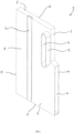
- the ventilator 1 of the present invention comprises a housing 2.
- the housing 2 is generally a sealed unit but has air inlets and outlets which will be described further below.
- the ventilator 1 is designed to be installed to the side of a window frame profile 100. It is therefore advantageous that the ventilator 1 should have as narrow a profile as possible.
- the arrangement depicted in figure 1 is generally rectangular having a relatively narrow front face 3 and wider side faces 4 and 12. While not intending to limit the present invention to any particular dimensions, a suitable width (thickness) of the housing can be in the order of up to 10 mm and preferably 5 mm. The inventors have found that this thickness is sufficient to allow adequate air into the ventilator while still maintaining a discrete and low-profile air inlet.
- the depth of the ventilator housing should be sufficient to provide a face which abuts with the side of a window frame profile element as described below, so as to provide a junction between the window frame profile element and the housing.
- the housing can be deep enough so as to allow for a fixing means 11 for attaching the ventilator to the window frame profile.
- the housing is substantially rectangular so that the side faces are substantially perpendicular to the front face and rear face, but the invention is not limited to this arrangement.
- the housing should provide a front face which, in use, is parallel with the front face of a window frame profile installation.
- the side face 4 does not necessarily need to be perpendicular to the front face 3, as long as it is dimensioned and configured to abut with a corresponding side face of the window frame profile to be ventilated.
- the front face 3 is substantially perpendicular to at least one side face 4.
- the depicted ventilator 1 is intended for injecting air into the right-hand side of a window frame profile 100.
- air enters the housing via the air intake opening 7 provided in the front face 3 of the housing 2, being substantially parallel with a front face of the window frame profile system.
- Air passes through the housing 2 and is inserted into the window frame profile out of the air passage opening 8 in the side face.
- this ventilator is intended for placement to the right side of a window frame profile 100, with air to be injected through the right side.
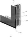
- the remaining figures 2 to 5 illustrate a ventilator 1 according to the invention intended to similarly inject air into a window frame profile via the right hand side of the window frame profile.
- the front face 3 is provided with an air intake opening 7.
- the air intake opening 7 is in the form of a longitudinal slot i.e. a slot which travels over the height of the housing.
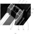
- the air intake opening 7 may simply be provided on the front face of the housing but, as shown, the air intake opening 7 is provided in a protruding rim 10 on the front face. This is advantageous because the region of the front face which is not part of the protruding rim is, in consequence, recessed. Therefore when the ventilator 1 is installed against the window frame profile 100, the non-rim recessed area of the front face can be filled with sealant material 106 as shown in figures 2 to 6. Therefore in the arrangement of figure 1 , the only visible part of the ventilator 1 once the ventilator 1 is installed is the rim 10 of the air intake opening 7.
- the width of the air intake opening 7 is substantially the same as the width of the housing (less the thickness of the material constituting the sidewalls). However it is not necessary that the width of the air intake opening 7 be substantially the same as the width of the housing. Rather, the width of the air intake opening 7 can be any width sufficient to allow entry of air into the housing and ultimately into the window frame profile.
- the height of the air intake opening 7 should be adequate to allow air into the housing and then into the window frame profile 100 to be ventilated. While not wishing to be limited to any particular dimensions, the present inventors have found that a height of around 30 to 60 mm is adequate.
- the air intake opening 7 may be described as a slot, meaning being a narrow aperture having a height greater than its width (which may be up to 10 mm and preferably around 5 mm) and preferably a height several times greater than its width.
- the air intake opening 7 should extend right down to the bottom face 6 of the housing. This is to prevent water (from condensation or rain) from becoming trapped inside the housing 6. For example, if the air intake opening 7 did not extend right down to the bottom face 6 of the housing 2, the housing 2 would effectively present a trough which could contain water.
- the bottom face 6 of the housing may be sloped downwardly in the direction of the front face 3. Therefore if any water was to enter the housing, for example due to driving rain, such water would flow out of the housing through the air intake opening 7.
- the bottom face 6 it may be preferred for the bottom face 6 to be substantially perpendicular to the other faces so that the overall housing 2 is cuboid. This is because, as above, window frame profile constructions are often rectangular so that the housing 2 should present a perpendicular face. Nevertheless should the bottom face 6 present a sloped surface this can also be achieved by including a sloped insert or sloped solid portion of housing (not illustrated).
- the air passage opening 8 is located higher up on the housing 2 than the air intake opening 7. This refers to the height of the ventilator 1 in the intended installed position.
- the air intake opening 7 is located in an area of the front face 3 toward the bottom face 6 (and preferably meets with the bottom face 6 as described above) whereas the air passage opening 8 is located in an area on the side face 4 that is toward the upper face 5 of the housing 2.
- the air passage opening 8 does not necessarily need to contact with the top face 5 because the same water draining effect is not required for the air passage opening 8.
- an area toward the bottom or top face it is generally meant that the openings are located relatively close to the bottom or top faces respectively, that is closer to the top face than the bottom face or closer than the bottom face than the top face.
- the air intake opening 7 may be provided in a position below half-height of the front face 3 and the air passage opening 8 may be provided in a position above half-height of the side face 4.
- the housing should be tall enough i.e. have a height great enough to prevent water from entering the housing to via the air intake opening and passing into the window frame profile via the air passage opening.
- the present inventors have found that a suitable height for the overall housing construction is approximately 80-100 mm and preferably 90 mm.
- the housing can optionally be provided with internal baffles (projections projecting from alternate interior sides of the housing) to help deflect water carried by air and prevent water from entering the profile.
- the air passage opening 8 is essentially an opening in the side face 4 of the housing 2. As shown, the air passage opening 8 is provided with an upstanding rim 9, which will be described in more detail below. However it is not necessary that the air intake opening 9 should have any upstanding rim or other similar upstanding features. All that is necessary is for the aperture of the air passage opening 8 to line up with a correspondingly dimensioned and configured opening in a hollow member of the window frame profile.
- the window frame profile assembly includes a hollow member 101.
- This hollow member 101 is the region of the window frame profile which needs to be ventilated to allow pressure equalisation so that water can escape, as already explained above in the background of the invention.
- This hollow member 101 may be an aluminium extrusion.
- this hollow member 101 also prevents a front surface 104 of the window frame profile, which may also be aluminium. Thus the front surface 104 is visible on an exterior or interior of a building and the remainder of the hollow member 101 is hidden within the window frame profile construction.
- the hollow member 101 has an opening or aperture 102 which forms an air passage together with the air passage opening 8 of the ventilator 1.
- This opening 102 may be pre-formed in the hollow member 101 or may be drilled out or otherwise formed in the hollow member 101 during installation, to match the air passage opening 8 of the ventilator 1.
- the opening 102 and the air passage opening 8 are also slot-like and rounded but this is just illustrative and in practice the opening can be of any shape or dimension, although again slots (elongate apertures) are preferred.
- the air passage opening 8 is provided with an upstanding rim 9 which is dimensioned and configured for projecting through the opening 102 in the hollow member 101 of the window frame profile 100.
- the rim may project up to 10mm from face 4 and preferably around 5 mm. This is preferred because the upstanding rim 9 allows for a positive engagement of the ventilator 1 through the opening 102 of the window frame profile, as shown in figure 4 .
- the housing 2 abuts the side of the window frame profile construction including abutting against the hollow member 101 of the window frame profile.
- the ventilator 1 may be installed for example by gluing.
- the housing 2 of the ventilator 1 may be provided with a fixing means for allowing a mechanical fixing between the housing 2 and the window frame profile 100.
- the window frame profile 100 presents a substantially T-shaped rail 103 and the housing 2 is provided with a longitudinal groove for engaging with corresponding projection 103 (rail) of the window frame profile. Therefore during installation, the groove 11 can be lined up with the projection 103 and slid along the projection to the base of the window frame profile arrangement.
- other mechanical fixing means are contemplated and may be used.
- the housing 2 when installed, is placed against the side of the window frame profile 100 so that the air intake opening 7 is presented to the right-hand side of the window frame profile 100 i.e. the air intake opening 7 extends to the side of the window frame profile to the extent of the thickness of the housing.
- the area between the window frame profile 100 and a wall is typically filled with sealant material 106 and this also surrounds the air intake opening 7, providing discrete ventilation.
- sealant material 106 As already explained, as the air intake opening 7 projects forward from the rest of the housing front face the remainder of the front face is recessed in comparison and may be filled with sealant.
- the housing 2 including the air intake opening 7 may be constructed of plastic or any other suitable material such as aluminium or fibreglass.
- the colour of the material used to manufacture the air intake opening matches either the colour of the finished window frame profile 100 or the colour of the sealant.
- a sealant may be black, white or anthracite in colour and the air intake opening 7 may be a corresponding colour so that the air intake opening 7 does not visually disturb.
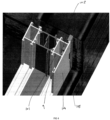
- the window frame profile 100 is provided with a cut-out portion 105 which is of a corresponding dimension to the air intake opening 7. Therefore the ventilator 1 is still seated against the side of the window frame profile 100 but rather than the air intake opening 7 extending beyond the periphery of the window frame profile (as in figure 3 ) the air intake opening is presented at the periphery but within the boundary of the window frame profile 100. Therefore if a customer prefers to have the ventilating slot in the window frame profile material itself rather than outside of the periphery of the window frame profile, the present invention also makes this possible. This may also be useful where there is no or insufficient sealing material 106 around the periphery of the window frame profile.
- the present invention provides the ventilator 1 herein described as a separate item.
- the ventilator 1 can be installed against already manufactured window frame profiles 100 without further modification other than the requirement to provide an aperture in the side of a hollow member to be ventilated, to correspond with the air passage opening 8 of the housing. That is, the ventilator 1 can be fitted to window frame systems purchased off-the-shelf that are not specially manufactured to match the ventilator.
- the invention provides a window frame system which includes the window frame profile 100 having at least one hollow side member 101 having an opening 102 for forming an air passage with the air passage opening of a ventilator, and the ventilator.
- the present invention also envisages a kit comprising a window frame system or components required to construct a window frame system together with at least one ventilator 1 as herein described and optionally a sealant material 106.
- a particular window frame system may be provided with more than one ventilator 1.
- the ventilator(s) of the invention may, in use, be mounted on any side of a window frame i.e. any of the top, bottom or side profiles, as desired.
- the accompanying drawings show side mountings but this is not limiting. However side mounting may be preferred because, as explained the height of the ventilator front face prevents water ingress. Also the ventilator(s) may be mounted at any point along a given profile, depending on aesthetic need.
- ventilators of the present invention have been described and depicted as facing an exterior of a building it is also possible for the ventilators to face an interior of a building, that is, the air intake opening or openings may be located at the interior of a building.
Landscapes
- Engineering & Computer Science (AREA)
- Civil Engineering (AREA)
- Structural Engineering (AREA)
- Chemical & Material Sciences (AREA)
- Combustion & Propulsion (AREA)
- Mechanical Engineering (AREA)
- General Engineering & Computer Science (AREA)
- Specific Sealing Or Ventilating Devices For Doors And Windows (AREA)
Claims (15)
- Ventilator (1) für ein Fensterrahmenprofil (100), der Ventilator umfassend:ein Gehäuse (2), aufweisend eine Vorderfläche (3), zumindest eine Seitenfläche (4), eine obere Fläche (5), eine untere Fläche (6), eine Lufteinlassöffnung (7) und eine Luftdurchtrittsöffnung (8), dadurch gekennzeichnet,dass die Vorderfläche mit der Lufteinlassöffnung (7) in einem Bereich der Vorderfläche in Richtung der unteren Fläche vorgesehen ist,dass die Seitenfläche mit der Luftdurchtrittsöffnung (8) in einem Bereich der Seitenfläche in Richtung der oberen Fläche vorgesehen ist, unddass die Luftdurchtrittsöffnung zum Ermöglichen eines Luftdurchtritts durch eine entsprechend dimensionierte und konfigurierte Öffnung (102) in einem hohlen Seitenelement (101) des Fensterrahmenprofils dimensioniert und konfiguriert ist.
- Ventilator nach Anspruch 1, wobei die Luftdurchtrittsöffnung mit einem zum Vorstehen durch die Fensterrahmenprofilöffnung dimensionierten und konfigurierten aufrechten Rand (9) vorgesehen ist.
- Ventilator nach Anspruch 1 oder Anspruch 2, wobei die Lufteinlassöffnung in einem nach vorne vorstehenden Rand (10) an der Vorderfläche vorgesehen ist, sodass die übrige Vorderfläche relativ zurückgesetzt ist.
- Ventilator nach einem der vorhergehenden Ansprüche, wobei die Seitenfläche ferner mit einem Befestigungsmittel (11) zum Befestigen des Ventilators an einem Seitenabschnitt des Fensterrahmenprofils vorgesehen ist.
- Ventilator nach Anspruch 4, wobei das Befestigungsmittel zumindest eine Längsnut für den Eingriff mit einem entsprechenden Vorsprung (103) des Fensterrahmenprofils umfasst, wobei die Längsachse in der Richtung zwischen der oberen Fläche und der unteren Fläche definiert ist.
- Ventilator nach einem der vorhergehenden Ansprüche, wobei die zumindest eine Seitenfläche im Wesentlichen senkrecht zu der Vorderfläche ist.
- Ventilator nach einem der vorhergehenden Ansprüche, wobei das Gehäuse in einem zwischen der oberen Fläche und der unteren Fläche gemessenen Querschnitt im Wesentlichen rechteckig ist und wobei die Abmessung der Vorderfläche geringer ist als die Abmessung der Seitenfläche.
- Ventilator nach einem der vorhergehenden Ansprüche, ferner umfassend eine zu der ersten Seitenfläche im Wesentlichen parallele zweite Seitenfläche (12) und eine zu der Vorderfläche im Wesentlichen parallele Rückfläche (13).
- Ventilator nach einem der vorhergehenden Ansprüche, wobei die untere Fläche in Richtung der Vorderfläche nach unten geneigt ist.
- Ventilator nach einem der vorhergehenden Ansprüche, wobei die Lufteinlassöffnung und/oder die Luftdurchtrittsöffnung Längsschlitze sind.
- Fensterrahmensystem, umfassend ein Fensterrahmenprofil (100) mit zumindest einem hohlen Seitenelement (101), umfassend eine Öffnung (102), und zumindest einen Ventilator (1) nach einem der vorhergehenden Ansprüche, wobei der oder jeder Ventilator mit dem oder jedem hohlen Seitenelement in Eingriff steht, sodass die Luftdurchtrittsöffnung (8) mit der Öffnung des hohlen Elements ausgerichtet ist und/oder mit dieser in Eingriff steht, um den Durchtritt von Luft durch diese zu ermöglichen.
- System nach Anspruch 11, wobei das Fensterrahmenprofil zwei hohle Seitenelemente umfasst und das System einen mit jedem hohlen Seitenelement in Eingriff stehenden Ventilator umfasst.
- System nach Anspruch 11 oder Anspruch 12, wobei die Lufteinlassöffnung in einem vorstehenden Rand (10) an der Vorderfläche (3) vorgesehen ist und wobei die Vorderkante des Randes im Wesentlichen bündig mit einer Vorderfläche (104) des Fensterrahmenprofils ist.
- System nach Anspruch 13, wobei der vorstehende Rand angrenzend an die Vorderfläche des Fensterrahmenprofils angeordnet ist.
- System nach Anspruch 13, wobei der vorstehende Rand in einem entsprechenden Aussparungsabschnitt (105) der Vorderfläche sitzt.
Priority Applications (4)
| Application Number | Priority Date | Filing Date | Title |
|---|---|---|---|
| ES21151572T ES2975565T3 (es) | 2021-01-14 | 2021-01-14 | Ventilador |
| EP21151572.1A EP4030030B1 (de) | 2021-01-14 | 2021-01-14 | Lüfter |
| CA3132677A CA3132677A1 (en) | 2021-01-14 | 2021-10-26 | Ventilator |
| US17/554,473 US12049785B2 (en) | 2021-01-14 | 2021-12-17 | Window frame ventilator |
Applications Claiming Priority (1)
| Application Number | Priority Date | Filing Date | Title |
|---|---|---|---|
| EP21151572.1A EP4030030B1 (de) | 2021-01-14 | 2021-01-14 | Lüfter |
Publications (2)
| Publication Number | Publication Date |
|---|---|
| EP4030030A1 EP4030030A1 (de) | 2022-07-20 |
| EP4030030B1 true EP4030030B1 (de) | 2024-03-20 |
Family
ID=74184448
Family Applications (1)
| Application Number | Title | Priority Date | Filing Date |
|---|---|---|---|
| EP21151572.1A Active EP4030030B1 (de) | 2021-01-14 | 2021-01-14 | Lüfter |
Country Status (4)
| Country | Link |
|---|---|
| US (1) | US12049785B2 (de) |
| EP (1) | EP4030030B1 (de) |
| CA (1) | CA3132677A1 (de) |
| ES (1) | ES2975565T3 (de) |
Family Cites Families (10)
| Publication number | Priority date | Publication date | Assignee | Title |
|---|---|---|---|---|
| US3314201A (en) * | 1964-11-23 | 1967-04-18 | Ador Corp | Weep hole construction for windows and the like |
| DE3427545A1 (de) * | 1984-07-26 | 1986-02-06 | Georg Jäger & Sohn KG, 6310 Grünberg | Fensterfluegel |
| BE1009282A3 (nl) * | 1995-03-31 | 1997-01-07 | Marc Speecke | Kozijn omvattende een ventilatie-inrichting, alsmede ventilatie-inrichting toepasbaar in het kozijn. |
| US5822934A (en) * | 1997-04-15 | 1998-10-20 | O'donnell; Richard | Drain |
| US6374557B1 (en) * | 2000-06-30 | 2002-04-23 | Ashland Products, Inc. | Weep hole construction |
| DE10335389A1 (de) * | 2003-07-25 | 2005-02-10 | Maico Holding Gmbh | Fenster-Lüftungsvorrichtung |
| DE202009017463U1 (de) * | 2009-12-28 | 2010-03-25 | Schwab, Harald | Vorrichtung zur Verringerung der Luftfeuchtigkeit in einem geschlossenen Gebäuderaum |
| EP2386710B1 (de) * | 2010-05-12 | 2017-09-27 | Kawneer France SAS | Fenster mit Entwässerungsöffnung |
| DE202010016800U1 (de) * | 2010-12-18 | 2011-03-10 | Norsk Hydro Asa | Fenster- oder Türkonstruktion in bevorzugt wärmegedämmter Ausführung |
| FR2981389B1 (fr) * | 2011-10-13 | 2014-08-08 | Composants Architecturaux Industrialises Pour Le Batiment | Accessoire de type buse, destine a equiper un profile de menuiserie, pour l'ecoulement de l'eau susceptible de s'accumuler dans une chambre dudit profile |
-
2021
- 2021-01-14 EP EP21151572.1A patent/EP4030030B1/de active Active
- 2021-01-14 ES ES21151572T patent/ES2975565T3/es active Active
- 2021-10-26 CA CA3132677A patent/CA3132677A1/en active Pending
- 2021-12-17 US US17/554,473 patent/US12049785B2/en active Active
Also Published As
| Publication number | Publication date |
|---|---|
| US20220220799A1 (en) | 2022-07-14 |
| CA3132677A1 (en) | 2022-07-14 |
| US12049785B2 (en) | 2024-07-30 |
| ES2975565T3 (es) | 2024-07-09 |
| EP4030030A1 (de) | 2022-07-20 |
Similar Documents
| Publication | Publication Date | Title |
|---|---|---|
| EP1186740B1 (de) | Anpassbares Zargensystem | |
| EP0870097B1 (de) | Entwässerungssystem für horizontal gleitende verschliesselemente | |
| US6374557B1 (en) | Weep hole construction | |
| KR102060165B1 (ko) | 유리난간대 및 이를 구비한 창호 | |
| US6769214B1 (en) | Strip for retaining storm door window elements | |
| US6170207B1 (en) | Frame with water stop and method of installation | |
| CA2009435C (en) | Window structure | |
| US4553361A (en) | Tiered drain channel for extruded door insert | |
| US20110139379A1 (en) | Door assembly | |
| US20220106827A1 (en) | Modular Sill | |
| KR102064578B1 (ko) | 창틀프레임의 배수를 원활하게 시키면서 외풍도 차단할 수 있는 방풍 및 배수구조 | |
| US20040128925A1 (en) | Continuous head and sill assembly and combined spacing member and side panel support therefore | |
| US12049785B2 (en) | Window frame ventilator | |
| US5836120A (en) | Door having integrally formed weep hole for drainage | |
| JPH05506897A (ja) | 換気装置付き引き戸組立体 | |
| KR200411850Y1 (ko) | 결로수 배수 구조를 구비한 창호 | |
| KR101366456B1 (ko) | 실외 장착형 글레이징 비드를 구비한 창호 및 그 조립 방법 | |
| GB2296320A (en) | Window frame element | |
| KR200394726Y1 (ko) | 폐 합성수지 폼을 이용한 루버창 | |
| JP2001317271A (ja) | 建物外壁の開口部周辺構造 | |
| JPS6316461Y2 (de) | ||
| EP4737670A1 (de) | Tür | |
| JPS6215437Y2 (de) | ||
| WO2004027193A1 (en) | Window or door structure | |
| US20060037261A1 (en) | Window cover system |
Legal Events
| Date | Code | Title | Description |
|---|---|---|---|
| PUAI | Public reference made under article 153(3) epc to a published international application that has entered the european phase |
Free format text: ORIGINAL CODE: 0009012 |
|
| STAA | Information on the status of an ep patent application or granted ep patent |
Free format text: STATUS: THE APPLICATION HAS BEEN PUBLISHED |
|
| AK | Designated contracting states |
Kind code of ref document: A1 Designated state(s): AL AT BE BG CH CY CZ DE DK EE ES FI FR GB GR HR HU IE IS IT LI LT LU LV MC MK MT NL NO PL PT RO RS SE SI SK SM TR |
|
| STAA | Information on the status of an ep patent application or granted ep patent |
Free format text: STATUS: REQUEST FOR EXAMINATION WAS MADE |
|
| 17P | Request for examination filed |
Effective date: 20230120 |
|
| RBV | Designated contracting states (corrected) |
Designated state(s): AL AT BE BG CH CY CZ DE DK EE ES FI FR GB GR HR HU IE IS IT LI LT LU LV MC MK MT NL NO PL PT RO RS SE SI SK SM TR |
|
| P01 | Opt-out of the competence of the unified patent court (upc) registered |
Effective date: 20230517 |
|
| GRAP | Despatch of communication of intention to grant a patent |
Free format text: ORIGINAL CODE: EPIDOSNIGR1 |
|
| STAA | Information on the status of an ep patent application or granted ep patent |
Free format text: STATUS: GRANT OF PATENT IS INTENDED |
|
| INTG | Intention to grant announced |
Effective date: 20231218 |
|
| GRAS | Grant fee paid |
Free format text: ORIGINAL CODE: EPIDOSNIGR3 |
|
| GRAA | (expected) grant |
Free format text: ORIGINAL CODE: 0009210 |
|
| STAA | Information on the status of an ep patent application or granted ep patent |
Free format text: STATUS: THE PATENT HAS BEEN GRANTED |
|
| AK | Designated contracting states |
Kind code of ref document: B1 Designated state(s): AL AT BE BG CH CY CZ DE DK EE ES FI FR GB GR HR HU IE IS IT LI LT LU LV MC MK MT NL NO PL PT RO RS SE SI SK SM TR |
|
| REG | Reference to a national code |
Ref country code: GB Ref legal event code: FG4D |
|
| REG | Reference to a national code |
Ref country code: CH Ref legal event code: EP |
|
| REG | Reference to a national code |
Ref country code: IE Ref legal event code: FG4D Ref country code: NL Ref legal event code: FP |
|
| REG | Reference to a national code |
Ref country code: DE Ref legal event code: R096 Ref document number: 602021010526 Country of ref document: DE |
|
| PG25 | Lapsed in a contracting state [announced via postgrant information from national office to epo] |
Ref country code: LT Free format text: LAPSE BECAUSE OF FAILURE TO SUBMIT A TRANSLATION OF THE DESCRIPTION OR TO PAY THE FEE WITHIN THE PRESCRIBED TIME-LIMIT Effective date: 20240320 |
|
| REG | Reference to a national code |
Ref country code: ES Ref legal event code: FG2A Ref document number: 2975565 Country of ref document: ES Kind code of ref document: T3 Effective date: 20240709 |
|
| REG | Reference to a national code |
Ref country code: LT Ref legal event code: MG9D |
|
| PG25 | Lapsed in a contracting state [announced via postgrant information from national office to epo] |
Ref country code: GR Free format text: LAPSE BECAUSE OF FAILURE TO SUBMIT A TRANSLATION OF THE DESCRIPTION OR TO PAY THE FEE WITHIN THE PRESCRIBED TIME-LIMIT Effective date: 20240621 |
|
| PG25 | Lapsed in a contracting state [announced via postgrant information from national office to epo] |
Ref country code: RS Free format text: LAPSE BECAUSE OF FAILURE TO SUBMIT A TRANSLATION OF THE DESCRIPTION OR TO PAY THE FEE WITHIN THE PRESCRIBED TIME-LIMIT Effective date: 20240620 Ref country code: HR Free format text: LAPSE BECAUSE OF FAILURE TO SUBMIT A TRANSLATION OF THE DESCRIPTION OR TO PAY THE FEE WITHIN THE PRESCRIBED TIME-LIMIT Effective date: 20240320 |
|
| PG25 | Lapsed in a contracting state [announced via postgrant information from national office to epo] |
Ref country code: RS Free format text: LAPSE BECAUSE OF FAILURE TO SUBMIT A TRANSLATION OF THE DESCRIPTION OR TO PAY THE FEE WITHIN THE PRESCRIBED TIME-LIMIT Effective date: 20240620 Ref country code: NO Free format text: LAPSE BECAUSE OF FAILURE TO SUBMIT A TRANSLATION OF THE DESCRIPTION OR TO PAY THE FEE WITHIN THE PRESCRIBED TIME-LIMIT Effective date: 20240620 Ref country code: LT Free format text: LAPSE BECAUSE OF FAILURE TO SUBMIT A TRANSLATION OF THE DESCRIPTION OR TO PAY THE FEE WITHIN THE PRESCRIBED TIME-LIMIT Effective date: 20240320 Ref country code: HR Free format text: LAPSE BECAUSE OF FAILURE TO SUBMIT A TRANSLATION OF THE DESCRIPTION OR TO PAY THE FEE WITHIN THE PRESCRIBED TIME-LIMIT Effective date: 20240320 Ref country code: GR Free format text: LAPSE BECAUSE OF FAILURE TO SUBMIT A TRANSLATION OF THE DESCRIPTION OR TO PAY THE FEE WITHIN THE PRESCRIBED TIME-LIMIT Effective date: 20240621 Ref country code: FI Free format text: LAPSE BECAUSE OF FAILURE TO SUBMIT A TRANSLATION OF THE DESCRIPTION OR TO PAY THE FEE WITHIN THE PRESCRIBED TIME-LIMIT Effective date: 20240320 Ref country code: BG Free format text: LAPSE BECAUSE OF FAILURE TO SUBMIT A TRANSLATION OF THE DESCRIPTION OR TO PAY THE FEE WITHIN THE PRESCRIBED TIME-LIMIT Effective date: 20240320 |
|
| REG | Reference to a national code |
Ref country code: AT Ref legal event code: MK05 Ref document number: 1667969 Country of ref document: AT Kind code of ref document: T Effective date: 20240320 |
|
| PG25 | Lapsed in a contracting state [announced via postgrant information from national office to epo] |
Ref country code: SE Free format text: LAPSE BECAUSE OF FAILURE TO SUBMIT A TRANSLATION OF THE DESCRIPTION OR TO PAY THE FEE WITHIN THE PRESCRIBED TIME-LIMIT Effective date: 20240320 Ref country code: LV Free format text: LAPSE BECAUSE OF FAILURE TO SUBMIT A TRANSLATION OF THE DESCRIPTION OR TO PAY THE FEE WITHIN THE PRESCRIBED TIME-LIMIT Effective date: 20240320 |
|
| PG25 | Lapsed in a contracting state [announced via postgrant information from national office to epo] |
Ref country code: IS Free format text: LAPSE BECAUSE OF FAILURE TO SUBMIT A TRANSLATION OF THE DESCRIPTION OR TO PAY THE FEE WITHIN THE PRESCRIBED TIME-LIMIT Effective date: 20240720 |
|
| PG25 | Lapsed in a contracting state [announced via postgrant information from national office to epo] |
Ref country code: SM Free format text: LAPSE BECAUSE OF FAILURE TO SUBMIT A TRANSLATION OF THE DESCRIPTION OR TO PAY THE FEE WITHIN THE PRESCRIBED TIME-LIMIT Effective date: 20240320 Ref country code: PT Free format text: LAPSE BECAUSE OF FAILURE TO SUBMIT A TRANSLATION OF THE DESCRIPTION OR TO PAY THE FEE WITHIN THE PRESCRIBED TIME-LIMIT Effective date: 20240722 |
|
| PG25 | Lapsed in a contracting state [announced via postgrant information from national office to epo] |
Ref country code: EE Free format text: LAPSE BECAUSE OF FAILURE TO SUBMIT A TRANSLATION OF THE DESCRIPTION OR TO PAY THE FEE WITHIN THE PRESCRIBED TIME-LIMIT Effective date: 20240320 Ref country code: CZ Free format text: LAPSE BECAUSE OF FAILURE TO SUBMIT A TRANSLATION OF THE DESCRIPTION OR TO PAY THE FEE WITHIN THE PRESCRIBED TIME-LIMIT Effective date: 20240320 |
|
| PG25 | Lapsed in a contracting state [announced via postgrant information from national office to epo] |
Ref country code: AT Free format text: LAPSE BECAUSE OF FAILURE TO SUBMIT A TRANSLATION OF THE DESCRIPTION OR TO PAY THE FEE WITHIN THE PRESCRIBED TIME-LIMIT Effective date: 20240320 |
|
| PG25 | Lapsed in a contracting state [announced via postgrant information from national office to epo] |
Ref country code: PL Free format text: LAPSE BECAUSE OF FAILURE TO SUBMIT A TRANSLATION OF THE DESCRIPTION OR TO PAY THE FEE WITHIN THE PRESCRIBED TIME-LIMIT Effective date: 20240320 |
|
| PG25 | Lapsed in a contracting state [announced via postgrant information from national office to epo] |
Ref country code: SK Free format text: LAPSE BECAUSE OF FAILURE TO SUBMIT A TRANSLATION OF THE DESCRIPTION OR TO PAY THE FEE WITHIN THE PRESCRIBED TIME-LIMIT Effective date: 20240320 |
|
| PG25 | Lapsed in a contracting state [announced via postgrant information from national office to epo] |
Ref country code: SM Free format text: LAPSE BECAUSE OF FAILURE TO SUBMIT A TRANSLATION OF THE DESCRIPTION OR TO PAY THE FEE WITHIN THE PRESCRIBED TIME-LIMIT Effective date: 20240320 Ref country code: SK Free format text: LAPSE BECAUSE OF FAILURE TO SUBMIT A TRANSLATION OF THE DESCRIPTION OR TO PAY THE FEE WITHIN THE PRESCRIBED TIME-LIMIT Effective date: 20240320 Ref country code: RO Free format text: LAPSE BECAUSE OF FAILURE TO SUBMIT A TRANSLATION OF THE DESCRIPTION OR TO PAY THE FEE WITHIN THE PRESCRIBED TIME-LIMIT Effective date: 20240320 Ref country code: PT Free format text: LAPSE BECAUSE OF FAILURE TO SUBMIT A TRANSLATION OF THE DESCRIPTION OR TO PAY THE FEE WITHIN THE PRESCRIBED TIME-LIMIT Effective date: 20240722 Ref country code: PL Free format text: LAPSE BECAUSE OF FAILURE TO SUBMIT A TRANSLATION OF THE DESCRIPTION OR TO PAY THE FEE WITHIN THE PRESCRIBED TIME-LIMIT Effective date: 20240320 Ref country code: IS Free format text: LAPSE BECAUSE OF FAILURE TO SUBMIT A TRANSLATION OF THE DESCRIPTION OR TO PAY THE FEE WITHIN THE PRESCRIBED TIME-LIMIT Effective date: 20240720 Ref country code: EE Free format text: LAPSE BECAUSE OF FAILURE TO SUBMIT A TRANSLATION OF THE DESCRIPTION OR TO PAY THE FEE WITHIN THE PRESCRIBED TIME-LIMIT Effective date: 20240320 Ref country code: CZ Free format text: LAPSE BECAUSE OF FAILURE TO SUBMIT A TRANSLATION OF THE DESCRIPTION OR TO PAY THE FEE WITHIN THE PRESCRIBED TIME-LIMIT Effective date: 20240320 Ref country code: AT Free format text: LAPSE BECAUSE OF FAILURE TO SUBMIT A TRANSLATION OF THE DESCRIPTION OR TO PAY THE FEE WITHIN THE PRESCRIBED TIME-LIMIT Effective date: 20240320 |
|
| PG25 | Lapsed in a contracting state [announced via postgrant information from national office to epo] |
Ref country code: IT Free format text: LAPSE BECAUSE OF FAILURE TO SUBMIT A TRANSLATION OF THE DESCRIPTION OR TO PAY THE FEE WITHIN THE PRESCRIBED TIME-LIMIT Effective date: 20240320 |
|
| REG | Reference to a national code |
Ref country code: DE Ref legal event code: R097 Ref document number: 602021010526 Country of ref document: DE |
|
| PG25 | Lapsed in a contracting state [announced via postgrant information from national office to epo] |
Ref country code: IT Free format text: LAPSE BECAUSE OF FAILURE TO SUBMIT A TRANSLATION OF THE DESCRIPTION OR TO PAY THE FEE WITHIN THE PRESCRIBED TIME-LIMIT Effective date: 20240320 |
|
| PG25 | Lapsed in a contracting state [announced via postgrant information from national office to epo] |
Ref country code: DK Free format text: LAPSE BECAUSE OF FAILURE TO SUBMIT A TRANSLATION OF THE DESCRIPTION OR TO PAY THE FEE WITHIN THE PRESCRIBED TIME-LIMIT Effective date: 20240320 |
|
| PLBE | No opposition filed within time limit |
Free format text: ORIGINAL CODE: 0009261 |
|
| STAA | Information on the status of an ep patent application or granted ep patent |
Free format text: STATUS: NO OPPOSITION FILED WITHIN TIME LIMIT |
|
| PG25 | Lapsed in a contracting state [announced via postgrant information from national office to epo] |
Ref country code: DK Free format text: LAPSE BECAUSE OF FAILURE TO SUBMIT A TRANSLATION OF THE DESCRIPTION OR TO PAY THE FEE WITHIN THE PRESCRIBED TIME-LIMIT Effective date: 20240320 |
|
| 26N | No opposition filed |
Effective date: 20241223 |
|
| PG25 | Lapsed in a contracting state [announced via postgrant information from national office to epo] |
Ref country code: SI Free format text: LAPSE BECAUSE OF FAILURE TO SUBMIT A TRANSLATION OF THE DESCRIPTION OR TO PAY THE FEE WITHIN THE PRESCRIBED TIME-LIMIT Effective date: 20240320 |
|
| REG | Reference to a national code |
Ref country code: CH Ref legal event code: PL |
|
| PG25 | Lapsed in a contracting state [announced via postgrant information from national office to epo] |
Ref country code: LU Free format text: LAPSE BECAUSE OF NON-PAYMENT OF DUE FEES Effective date: 20250114 Ref country code: MC Free format text: LAPSE BECAUSE OF FAILURE TO SUBMIT A TRANSLATION OF THE DESCRIPTION OR TO PAY THE FEE WITHIN THE PRESCRIBED TIME-LIMIT Effective date: 20240320 |
|
| PG25 | Lapsed in a contracting state [announced via postgrant information from national office to epo] |
Ref country code: CH Free format text: LAPSE BECAUSE OF NON-PAYMENT OF DUE FEES Effective date: 20250131 |
|
| PG25 | Lapsed in a contracting state [announced via postgrant information from national office to epo] |
Ref country code: IE Free format text: LAPSE BECAUSE OF NON-PAYMENT OF DUE FEES Effective date: 20250114 |
|
| PGFP | Annual fee paid to national office [announced via postgrant information from national office to epo] |
Ref country code: NL Payment date: 20260126 Year of fee payment: 6 |
|
| PGFP | Annual fee paid to national office [announced via postgrant information from national office to epo] |
Ref country code: GB Payment date: 20260127 Year of fee payment: 6 |
|
| PGFP | Annual fee paid to national office [announced via postgrant information from national office to epo] |
Ref country code: ES Payment date: 20260202 Year of fee payment: 6 |
|
| PGFP | Annual fee paid to national office [announced via postgrant information from national office to epo] |
Ref country code: DE Payment date: 20260128 Year of fee payment: 6 |
|
| PGFP | Annual fee paid to national office [announced via postgrant information from national office to epo] |
Ref country code: BE Payment date: 20260127 Year of fee payment: 6 |
|
| PGFP | Annual fee paid to national office [announced via postgrant information from national office to epo] |
Ref country code: FR Payment date: 20260126 Year of fee payment: 6 |