EP4029697B1 - Schätzverfahren, druckverfahren und druckvorrichtung - Google Patents
Schätzverfahren, druckverfahren und druckvorrichtung Download PDFInfo
- Publication number
- EP4029697B1 EP4029697B1 EP21216278.8A EP21216278A EP4029697B1 EP 4029697 B1 EP4029697 B1 EP 4029697B1 EP 21216278 A EP21216278 A EP 21216278A EP 4029697 B1 EP4029697 B1 EP 4029697B1
- Authority
- EP
- European Patent Office
- Prior art keywords
- base material
- expansion
- data
- learning
- printing
- Prior art date
- Legal status (The legal status is an assumption and is not a legal conclusion. Google has not performed a legal analysis and makes no representation as to the accuracy of the status listed.)
- Active
Links
Images


Classifications
-
- B—PERFORMING OPERATIONS; TRANSPORTING
- B41—PRINTING; LINING MACHINES; TYPEWRITERS; STAMPS
- B41J—TYPEWRITERS; SELECTIVE PRINTING MECHANISMS, i.e. MECHANISMS PRINTING OTHERWISE THAN FROM A FORME; CORRECTION OF TYPOGRAPHICAL ERRORS
- B41J2/00—Typewriters or selective printing mechanisms characterised by the printing or marking process for which they are designed
- B41J2/005—Typewriters or selective printing mechanisms characterised by the printing or marking process for which they are designed characterised by bringing liquid or particles selectively into contact with a printing material
- B41J2/01—Ink jet
- B41J2/21—Ink jet for multi-colour printing
- B41J2/2132—Print quality control characterised by dot disposition, e.g. for reducing white stripes or banding
- B41J2/2135—Alignment of dots
-
- B—PERFORMING OPERATIONS; TRANSPORTING
- B41—PRINTING; LINING MACHINES; TYPEWRITERS; STAMPS
- B41J—TYPEWRITERS; SELECTIVE PRINTING MECHANISMS, i.e. MECHANISMS PRINTING OTHERWISE THAN FROM A FORME; CORRECTION OF TYPOGRAPHICAL ERRORS
- B41J11/00—Devices or arrangements of selective printing mechanisms, e.g. ink-jet printers or thermal printers, for supporting or handling copy material in sheet or web form
- B41J11/0015—Devices or arrangements of selective printing mechanisms, e.g. ink-jet printers or thermal printers, for supporting or handling copy material in sheet or web form for treating before, during or after printing or for uniform coating or laminating the copy material before or after printing
- B41J11/002—Curing or drying the ink on the copy materials, e.g. by heating or irradiating
-
- B—PERFORMING OPERATIONS; TRANSPORTING
- B41—PRINTING; LINING MACHINES; TYPEWRITERS; STAMPS
- B41J—TYPEWRITERS; SELECTIVE PRINTING MECHANISMS, i.e. MECHANISMS PRINTING OTHERWISE THAN FROM A FORME; CORRECTION OF TYPOGRAPHICAL ERRORS
- B41J11/00—Devices or arrangements of selective printing mechanisms, e.g. ink-jet printers or thermal printers, for supporting or handling copy material in sheet or web form
- B41J11/008—Controlling printhead for accurately positioning print image on printing material, e.g. with the intention to control the width of margins
-
- B—PERFORMING OPERATIONS; TRANSPORTING
- B41—PRINTING; LINING MACHINES; TYPEWRITERS; STAMPS
- B41J—TYPEWRITERS; SELECTIVE PRINTING MECHANISMS, i.e. MECHANISMS PRINTING OTHERWISE THAN FROM A FORME; CORRECTION OF TYPOGRAPHICAL ERRORS
- B41J11/00—Devices or arrangements of selective printing mechanisms, e.g. ink-jet printers or thermal printers, for supporting or handling copy material in sheet or web form
- B41J11/36—Blanking or long feeds; Feeding to a particular line, e.g. by rotation of platen or feed roller
- B41J11/42—Controlling printing material conveyance for accurate alignment of the printing material with the printhead; Print registering
- B41J11/46—Controlling printing material conveyance for accurate alignment of the printing material with the printhead; Print registering by marks or formations on the paper being fed
-
- B—PERFORMING OPERATIONS; TRANSPORTING
- B41—PRINTING; LINING MACHINES; TYPEWRITERS; STAMPS
- B41J—TYPEWRITERS; SELECTIVE PRINTING MECHANISMS, i.e. MECHANISMS PRINTING OTHERWISE THAN FROM A FORME; CORRECTION OF TYPOGRAPHICAL ERRORS
- B41J2/00—Typewriters or selective printing mechanisms characterised by the printing or marking process for which they are designed
- B41J2/005—Typewriters or selective printing mechanisms characterised by the printing or marking process for which they are designed characterised by bringing liquid or particles selectively into contact with a printing material
- B41J2/01—Ink jet
- B41J2/21—Ink jet for multi-colour printing
- B41J2/2132—Print quality control characterised by dot disposition, e.g. for reducing white stripes or banding
- B41J2/2146—Print quality control characterised by dot disposition, e.g. for reducing white stripes or banding for line print heads
-
- C—CHEMISTRY; METALLURGY
- C09—DYES; PAINTS; POLISHES; NATURAL RESINS; ADHESIVES; COMPOSITIONS NOT OTHERWISE PROVIDED FOR; APPLICATIONS OF MATERIALS NOT OTHERWISE PROVIDED FOR
- C09D—COATING COMPOSITIONS, e.g. PAINTS, VARNISHES OR LACQUERS; FILLING PASTES; CHEMICAL PAINT OR INK REMOVERS; INKS; CORRECTING FLUIDS; WOODSTAINS; PASTES OR SOLIDS FOR COLOURING OR PRINTING; USE OF MATERIALS THEREFOR
- C09D11/00—Inks
- C09D11/30—Inkjet printing inks
- C09D11/40—Ink-sets specially adapted for multi-colour inkjet printing
-
- G—PHYSICS
- G06—COMPUTING OR CALCULATING; COUNTING
- G06N—COMPUTING ARRANGEMENTS BASED ON SPECIFIC COMPUTATIONAL MODELS
- G06N3/00—Computing arrangements based on biological models
- G06N3/02—Neural networks
- G06N3/04—Architecture, e.g. interconnection topology
- G06N3/0499—Feedforward networks
-
- G—PHYSICS
- G06—COMPUTING OR CALCULATING; COUNTING
- G06N—COMPUTING ARRANGEMENTS BASED ON SPECIFIC COMPUTATIONAL MODELS
- G06N3/00—Computing arrangements based on biological models
- G06N3/02—Neural networks
- G06N3/08—Learning methods
-
- G—PHYSICS
- G06—COMPUTING OR CALCULATING; COUNTING
- G06N—COMPUTING ARRANGEMENTS BASED ON SPECIFIC COMPUTATIONAL MODELS
- G06N3/00—Computing arrangements based on biological models
- G06N3/02—Neural networks
- G06N3/08—Learning methods
- G06N3/09—Supervised learning
-
- B—PERFORMING OPERATIONS; TRANSPORTING
- B41—PRINTING; LINING MACHINES; TYPEWRITERS; STAMPS
- B41J—TYPEWRITERS; SELECTIVE PRINTING MECHANISMS, i.e. MECHANISMS PRINTING OTHERWISE THAN FROM A FORME; CORRECTION OF TYPOGRAPHICAL ERRORS
- B41J15/00—Devices or arrangements of selective printing mechanisms, e.g. ink-jet printers or thermal printers, specially adapted for supporting or handling copy material in continuous form, e.g. webs
- B41J15/04—Supporting, feeding, or guiding devices; Mountings for web rolls or spindles
-
- G—PHYSICS
- G06—COMPUTING OR CALCULATING; COUNTING
- G06N—COMPUTING ARRANGEMENTS BASED ON SPECIFIC COMPUTATIONAL MODELS
- G06N3/00—Computing arrangements based on biological models
- G06N3/02—Neural networks
- G06N3/04—Architecture, e.g. interconnection topology
- G06N3/044—Recurrent networks, e.g. Hopfield networks
-
- G—PHYSICS
- G06—COMPUTING OR CALCULATING; COUNTING
- G06N—COMPUTING ARRANGEMENTS BASED ON SPECIFIC COMPUTATIONAL MODELS
- G06N7/00—Computing arrangements based on specific mathematical models
- G06N7/01—Probabilistic graphical models, e.g. probabilistic networks
Definitions
- the present invention relates to a technique for estimating the expansion/contraction state of an elongated strip-shaped base material in a printing apparatus that ejects ink onto a surface of the base material while transporting the base material in a longitudinal direction thereof.
- An inkjet printing apparatus for printing an image on an elongated strip-shaped base material by ejecting ink from a plurality of heads while transporting the base material in a longitudinal direction thereof has heretofore been known.
- the inkjet printing apparatus ejects inks of different colors from the respective heads.
- the inkjet printing apparatus prints a multi-color image on a surface of the base material by superimposing single-color images formed by the respective inks of the different colors.
- Such a conventional printing apparatus is disclosed, for example, in Japanese Patent Application Laid-Open No. 2004-268361 .
- the base material expands or contracts slightly when the base material absorbs the inks or when the inks on the base material become dry. As a result, a printed image formed on the surface of the base material is distorted. Also, there are cases in which the position of the inks ejected from the heads is improper due to the expansion and contraction of the base material. In conventional techniques, various parameters for the printing apparatus have been set to minimize the degradation in print quality resulting from the expansion and contraction of the base material.
- the amount of expansion/contraction of the base material varies depending on various conditions such as the tension applied to the base material, the type of base material, and the type of ink.
- the amount of expansion/contraction of the base material varies between printing apparatuses of the same type due to differences between machines. For these reasons, it has been difficult to set the aforementioned parameters uniquely.
- the expansion/contraction state of the base material which varies depending on image data to be printed, cannot be known prior to printing in conventional techniques.
- US 2020/307279 A1 discloses a method implemented in a duplex printer for determining a model parameter for predicting a shrinkage of a media sheet after printing the front side.
- the shrinkage of the media sheet after the front side has been printed is measured based on an outer contour of the media sheet and an outer contour of the printed front side image.
- the corresponding contours are obtained by a scanner.
- a printing position of a back side image is adjusted without adjusting the printing position of the front side image.
- Further prior documents are US 2021 /014379 A1 and US 2021 /014379 A1 .
- a first aspect of the present invention is intended for a method of estimating the expansion/contraction state of an elongated strip-shaped base material in a printing apparatus that ejects ink onto a surface of the base material while transporting the base material in a longitudinal direction thereof.
- the method comprises: a) a data acquisition step for acquiring submitted data that is image data to be printed; and b) an estimation step for outputting an estimation result indicating the expansion/contraction state of the base material resulting from ink, based on the submitted data, prior to printing of the submitted data.
- a second aspect of the present invention is intended for the method of the first aspect, which further comprises c) a learning step for generating an estimation model that is able to estimate the expansion/contraction state of the base material by means of machine learning using learning data that is image data for learning as an input variable and the expansion/contraction state of the base material at the time of printing of the learning data in the printing apparatus as teacher data, wherein the submitted data is inputted to the estimation model, and the expansion/contraction state outputted from the estimation model is used as the estimation result in the estimation step (the step b)).
- a third aspect of the present invention is intended for the method of the second aspect, wherein the learning data in the step c) is image data in which a plurality of marks arranged in spaced apart relation are incorporated, and wherein the expansion/contraction state that becomes the teacher data is measured in the learning step (the step c)) based on the positions of the marks on the base material at the time of printing of the learning data in the printing apparatus.
- a fourth aspect of the present invention is intended for the method of the third aspect, wherein each of the marks includes: a base figure of a first color; and a mark figure of a second color different from the first color, the mark figure being in a position overlaid on the base figure.
- a fifth aspect of the present invention is intended for the method of the fourth aspect, wherein the first color is white, and the second color is black.
- a sixth aspect of the present invention is intended for the method of any one of the third to fifth aspects, wherein the teacher data indicates a change in distance between adjacent ones of the marks.
- a seventh aspect of the present invention is intended for the method of any one of the third to fifth aspects, wherein the teacher data indicates the amount of displacement of each of the marks.
- An eighth aspect of the present invention is intended for the method of any one of the second to seventh aspects, wherein the learning data is image data including a plurality of regions different in density value or coverage rate.
- a ninth aspect of the present invention is intended for a method of printing using the estimation method as recited in any one of the first to eighth aspects.
- the method further comprises d) a printing step for ejecting ink onto the surface of the base material while correcting the ejection position of ink onto the base material, based on the estimation result, the step d) being performed after the data acquisition step (the step a)) and the estimation step (the step b)).
- a tenth aspect of the present invention is intended for a printing apparatus, which comprises: a data acquisition part for acquiring submitted data that is image data to be printed; a transport mechanism for transporting an elongated strip-shaped base material along a predetermined transport path in a longitudinal direction thereof; a head for ejecting ink onto a surface of the base material being transported by the transport mechanism, based on the submitted data; and an estimation part for outputting an estimation result indicating the expansion/contraction state of the base material resulting from the ink, based on the submitted data, prior to printing of the submitted data.
- An eleventh aspect of the present invention is intended for the printing apparatus of the tenth aspect, which further comprises: a camera for photographing a printing surface of the base material in a position downstream from the head along the transport path; an expansion/contraction state measurement part for measuring the expansion/contraction state of the base material, based on a photographic image from the camera; and a learning part for generating an estimation model that is able to estimate the expansion/contraction state of the base material by means of machine learning using learning data that is image data for learning as an input variable and the expansion/contraction state at the time of printing of the learning data as teacher data, wherein the estimation part inputs the submitted data to the estimation model, and uses the expansion/contraction state outputted from the estimation model as the estimation result.
- a twelfth aspect of the present invention is intended for the printing apparatus of the tenth or eleventh aspect, which further comprises: a correction value calculation part for calculating a correction value, based on the estimation result; and an operation control part for controlling the transport mechanism and the head so as to eject the ink onto the surface of the base material while correcting the ejection position of the ink onto the base material, based on the correction value.
- the expansion/contraction state of the base material resulting from the ink is estimated, based on the submitted data, prior to the printing. This provides the estimation result of the expansion/contraction state in accordance with the submitted data. Thus, the submitted data is printed in consideration of the estimation result of the expansion/contraction state.
- the use of the machine learning makes it easy to respond to changes in conditions, as compared with the process of calculating the estimation result of the expansion/contraction state based on a formula or table indicating a relationship between the image data and the expansion/contraction state.
- the plurality of marks incorporated in the learning data make it easy to obtain the expansion/contraction state of the base material that becomes the teacher data.
- the mark figure is recognizable regardless of the color of the image serving as a background.
- the teacher data represents the local amount of expansion/contraction for each region.
- the teacher data which does not represent the accumulated amount of displacement, is easy to handle in the machine learning.
- the teacher data represents changes in coordinate position of each portion of the base material.
- the estimation result outputted from the estimation model also represents changes in coordinate position of each portion of the base material.
- the coordinate position of the ink for ejection onto the base material is easily corrected based on the estimation result.
- the amount of expansion/contraction of the base material in accordance with the density value or the coverage rate is learned.
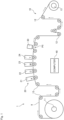
- Fig. 1 is a diagram showing a configuration of a printing apparatus 1 according to a preferred embodiment of the present invention.
- the printing apparatus 1 is an apparatus for printing an image on a surface of an elongated strip-shaped base material 9 by ejecting ink droplets from a plurality of heads 21 to 24 toward the base material 9 while transporting the base material 9.
- the base material 9 may be printing paper or a resin film.
- the base material 9 may also be metal foil or a glass base material.
- the printing apparatus 1 includes a transport mechanism 10, a printing part 20, a camera 30, and a computer 40.
- the transport mechanism 10 is a mechanism for transporting the base material 9 in a transport direction extending along the length of the base material 9.
- the transport mechanism 10 of the present preferred embodiment includes an unwinder 11, a plurality of transport rollers 12, and a winder 13.
- the base material 9 is unwound from the unwinder 11, and is transported along a transport path formed by the transport rollers 12.
- Each of the transport rollers 12 rotates about an axis extending in a direction perpendicular to the transport direction to guide the base material 9 downstream along the transport path.
- the transported base material 9 is wound and collected on the winder 13.
- the base material 9 is tensioned in the transport direction. This suppresses slack and wrinkles in the base material 9 during the transport.
- the printing part 20 is a processing part for ejecting droplets of inks (ink droplets) toward the base material 9 being transported by the transport mechanism 10.
- the printing part 20 of the present preferred embodiment includes a first head 21, a second head 22, a third head 23, and a fourth head 24.
- the first head 21, the second head 22, the third head 23, and the fourth head 24 are arranged in spaced apart relation in the transport direction of the base material 9.
- the base material 9 is transported under the four heads 21 to 24, with a printing surface thereof facing upward.
- Fig. 2 is a partial top view of the printing apparatus 1 in the vicinity of the printing part 20.
- each of the heads 21 to 24 has a lower surface provided with a plurality of nozzles 201 arranged parallel to the width direction of the base material 9.
- the first, second, third, and fourth heads 21, 22, 23, and 24 eject ink droplets of four colors, i.e., K (black), C (cyan), M (magenta), and Y (yellow), respectively, which serve as color components of a multi-color image from the nozzles 201 toward an upper surface of the base material 9.
- the first head 21 ejects K-color ink droplets toward the upper surface of the base material 9 in a first printing position P1 lying on the transport path.
- the second head 22 ejects C-color ink droplets toward the upper surface of the base material 9 in a second printing position P2.
- the second printing position P2 is downstream from the first printing position P1.
- the third head 23 ejects M-color ink droplets toward the upper surface of the base material 9 in a third printing position P3.
- the third printing position P3 is downstream from the second printing position P2.
- the fourth head 24 ejects Y-color ink droplets toward the upper surface of the base material 9 in a fourth printing position P4.
- the fourth printing position P4 is downstream from the third printing position P3.
- a fixing part for fixing the inks on the printing surface of the base material 9 may be further provided downstream of the heads 21 to 24 as seen in the transport direction.
- the fixing part for example, blows a heated gas toward the base material 9 to dry the inks adhering to the base material 9.
- the fixing part may be of the type which irradiates UV-curable inks with UV light to cure the inks.
- the camera 30 is an imaging device for photographing the printing surface of the base material 9 having passed the printing part 20.
- the camera 30 is disposed in opposed relation to the printing surface of the base material 9 in a photographing position P5 downstream from the four heads 21 to 24 along the transport path.
- a line sensor including a plurality of imaging elements, such as CCD, CMOS, and other imaging elements, arranged in the width direction is used as the camera 30.
- the camera 30 photographs the printing surface of the base material 9 to thereby acquire a photographic image. Then, the camera 30 sends the acquired photographic image to the computer 40.
- the computer 40 is an information processing device for controlling the printing apparatus 1.
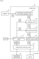
- Fig. 3 is a block diagram showing connections between the computer 40 and the components of the printing apparatus 1.
- the computer 40 includes a processor 401 such as a CPU, a memory 402 such as a RAM, and a storage part 403 such as a hard disk drive.
- a computer program 404 for execution of a learning process and a printing process to be described later is stored in the storage part 403.
- the computer 40 is connected to the transport mechanism 10, the four heads 21 to 24, and the camera 30 for communication therewith.
- the computer 40 is also connected to a server 2 that is an external storage device for communication therewith.
- Submitted data D1 is stored in the server 2.
- the submitted data D1 is image data to be printed in the printing apparatus 1 for obtainment of a printed product.
- the computer 40 acquires the submitted data D 1 from the server 2, and controls the operations of the transport mechanism 10 and the four heads 21 to 24, based on the submitted data D1.
- a large number of learning data D2 for use in the learning process to be described later are also stored in the server 2.
- each of the four heads 21 to 24 ejects ink droplets to thereby print a single-color image on the upper surface of the base material 9.
- a multi-color image is formed on the upper surface of the base material 9 by superimposing the four single-color images. If the ink droplets ejected from the four heads 21 to 24 are out of position relative to each other on the base material 9, the image quality of a printed product is lowered. Controlling such misalignment (misregistration) between the single-color images on the base material 9 within an allowable range is an important factor for obtainment of high-quality printed products.
- the base material 9 expands and contracts non-uniformly when the inks are absorbed by the base material 9 or when the inks on the base material 9 become dry.
- the occurrence of such expansion and contraction of the base material 9 distorts a printed image formed on the printing surface.
- the occurrence of such expansion and contraction of the base material 9 also makes the aforementioned misregistration prone to occur.
- the computer 40 of the printing apparatus 1 has the function of estimating the expansion/contraction state of the base material 9 prior to printing based on the submitted data D1 to perform printing while correcting the ejection positions of the ink droplets through the use of the estimation result.
- Fig. 4 is a block diagram conceptually showing functions of the computer 40.
- the computer 40 includes a data acquisition part 41, an expansion/contraction state measurement part 42, a learning part 43, an estimation part 44, a correction value calculation part 45, and an operation control part 46.
- Functions of the data acquisition part 41, the expansion/contraction state measurement part 42, the learning part 43, the estimation part 44, the correction value calculation part 45, and the operation control part 46 are implemented by the processor 401 of the computer 40 operating in accordance with the computer program 404.
- the data acquisition part 41 is a processing part for acquiring the submitted data D1 and the learning data D2.
- the data acquisition part 41 reads the submitted data D1 and the learning data D2 from the server 2.
- the data acquisition part 41 inputs the read learning data D2 to the learning part 43 and the operation control part 46.
- the data acquisition part 41 also inputs the read submitted data D1 to the estimation part 44 and the operation control part 46.
- the expansion/contraction state measurement part 42 is a processing part for measuring the expansion/contraction state of the base material 9, based on a photographic image D3 sent from the camera 30. A method of measuring the expansion/contraction state of the base material 9 will be described later.
- the expansion/contraction state measurement part 42 inputs a measured expansion/contraction state D4 of the base material 9 to the learning part 43.
- the learning part 43 is a processing part for learning a relationship between image data and the expansion/contraction state of the base material 9 which will result when the image data is printed.
- This printing apparatus 1 performs the learning process by means of the learning part 43 prior to the printing of the submitted data D1 for obtainment of a printed product.
- the learning data D2 is inputted to the aforementioned operation control part 46 and the learning part 43.
- the operation control part 46 controls the operations of the transport mechanism 10 and the printing part 20, based on the learning data D2.
- the learning data D2 is printed on the printing surface of the base material 9.
- the camera 30 photographs the base material 9 subjected to the printing.
- the learning part 43 uses the learning data D2 as an input variable and the expansion/contraction state D4 measured by the expansion/contraction state measurement part 42 as teacher data to perform the learning process by means of a supervised machine learning algorithm.
- the learning part 43 repeats such a learning process until a predetermined termination condition is satisfied.
- the learning part 43 generates an estimation model M.
- the estimation model M outputs an estimation result indicating the expansion/contraction state of the base material 9, based on the inputted image data. The details on the learning process will be described later.
- the learning part 43 uses, for example, deep learning (a multi-layer neural network) as the machine learning algorithm.
- deep learning a multi-layer neural network
- the machine learning algorithm used by the learning part 43 is not limited to the deep learning.
- Other machine learning algorithms such as Markov random fields (MRFs) and Boltzmann machines may be used in place of the deep learning.
- MRFs Markov random fields
- Boltzmann machines may be used in place of the deep learning.
- the estimation part 44 is a processing part for estimating the expansion/contraction state of the base material 9 which will result when the submitted data D1 is printed, based on the submitted data D1.
- the estimation part 44 uses the estimation model M generated by the learning part 43 to perform an estimation process.
- the estimation part 44 inputs the submitted data D1 acquired by the data acquisition part 41 to the estimation model M.
- the expansion/contraction state of the base material 9 corresponding to the submitted data D1 is outputted from the estimation model M.
- the estimation part 44 uses the expansion/contraction state outputted from the estimation model M as an estimation result D5.
- the correction value calculation part 45 is a processing part for calculating a correction value D6, based on the estimation result D5.
- the correction value calculation part 45 calculates the correction value D6 in a direction for canceling the amount of expansion/contraction of the base material 9 indicated by the estimation result D5.
- the calculated correction value D6 is inputted to the operation control part 46.
- the operation control part 46 is a processing part for controlling the operations of the transport mechanism 10 and the four heads 21 to 24.
- the operation control part 46 When printing the aforementioned learning data D2, the operation control part 46 outputs a command value based on the learning data D2 to the transport mechanism 10 and the four heads 21 to 24.
- the operation control part 46 brings the transport mechanism 10 and the four heads 21 to 24 into operation to print the learning data D2 on the printing surface of the base material 9.
- the operation control part 46 corrects a command value based on the submitted data D1 with the use of the correction value D6.
- the operation control part 46 outputs the corrected command value to the transport mechanism 10 and the four heads 21 to 24.
- the operation control part 46 brings the transport mechanism 10 and the four heads 21 to 24 into operation to correct and print the submitted data D1 on the printing surface of the base material 9.
- Fig. 5 is a flow diagram showing a procedure for the learning process. This learning process is performed prior to the printing of the submitted data D1 for obtainment of a printed product.
- the data acquisition part 41 initially reads the learning data D2 from the server 2, as shown in Fig. 5 . Then, the data acquisition part 41 inputs the learning data D2 to the learning part 43 and the operation control part 46 (Step S1).
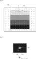
- Fig. 6 is a view showing an example of the learning data D2.
- the learning data D2 is image data in which a plurality of grid marks 52 are incorporated in an image 51 such as a picture or a pattern.
- the multiple learning data D2 have respective images 51 different from each other.
- the amount of expansion/contraction of the base material 9 varies depending on the amounts of inks ejected onto the base material 9. It is hence desirable that the image 51 of the learning data D2 is an image including a plurality of regions different in density value or coverage rate. This allows the learning of the amount of expansion/contraction of the base material 9 in accordance with the density value or the coverage rate.
- Each of the grid marks 52 is a mark indicating a predetermined coordinate position in the learning data D2.
- the grid marks 52 are arranged over the entire learning data D2.
- the grid marks 52 are also arranged in spaced apart relation in the transport direction and the width direction of the base material 9.
- the grid marks 52 are disposed on the front side of the image 51.
- Fig. 7 is an enlarged view of one part of the learning data D2.
- a grid mark 52 of the present preferred embodiment is comprised of a base figure 521 and a mark figure 522.
- the base figure 521 is a rectangular figure filled in with white (0% density value).
- the mark figure 522 is a black (100% density value) cross-shaped figure overlaid on the front side of the base figure 521.
- the grid mark 52 is placed on a black background.
- the mark figure 522 is recognizable because the mark figure 522 is on the white base figure 521 while the background and the mark figure 522 are of the same black color.
- the grid mark 52 is placed on a white background. In such a case, a boundary between the base figure 521 and the background which are of the same white color is not recognizable, but the black mark figure 522 is recognizable.
- the grid mark 52 is comprised of the white base figure 521 and the black mark figure 522 that is overlaid on the front side of the base figure 521 in this manner. This makes the mark figure 522 recognizable regardless of the color of the image 51 serving as the background.
- Step S1 the operation control part 46 controls the operations of the transport mechanism 10 and the four heads 21 to 24, based on the learning data D2.
- the plurality of grid marks 52 together with the image 51 are printed on the printing surface of the base material 9.
- the camera 30 photographs the printing surface of the base material 9 on which the learning data D2 is printed (Step S3).
- the photographic image D3 obtained by the photographing is sent from the camera 30 to the computer 40 and inputted to the expansion/contraction state measurement part 42.
- the expansion/contraction state measurement part 42 measures the expansion/contraction state of the base material 9, based on the photographic image D3 sent from the camera 30 (Step S4). Specifically, the expansion/contraction state measurement part 42 extracts the positions of the grid marks 52 on the base material 9 from the photographic image D3. Then, the expansion/contraction state measurement part 42 measures the expansion/contraction state of the base material 9, based on the positions of the grid marks 52. As mentioned above, each of the grid marks 52 is comprised of the white base figure 521 and the black mark figure 522. This makes the positions of all of the grid marks 52 recognizable regardless of the color and density of the image 51 serving as the background. Thus, the expansion/contraction state of the base material 9 is measured with accuracy.
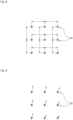
- Fig. 8 is a view showing an example of a method of measuring the expansion/contraction state of the base material 9.
- the expansion/contraction state measurement part 42 measures a distance between adjacent ones of the grid marks 52 in the photographic image D3. Then, the expansion/contraction state measurement part 42 calculates a difference between the measured distance between the grid marks 52 and the distance between the grid marks 52 in the learning data D2 as the amount of expansion/contraction. In other words, a change in the distance between the adjacent grid marks 52 is measured as the amount of expansion/contraction in the method of Fig. 8 .
- the expansion/contraction state measurement part 42 performs such a measurement of the amount of expansion/contraction for all of the adjacent grid marks 52 in the photographic image D3. As a result, a heat map showing a distribution of the amounts of expansion/contraction on the base material 9 is provided.
- the amount of displacement of each region on the base material 9 is influenced not only by the amount of expansion/contraction of that region but also by the amount of expansion/contraction of other regions, and becomes the accumulation value of these amounts of expansion/contraction.
- the heat map provided by the measurement method of Fig. 8 represents the local amount of expansion/contraction for each region of the base material 9. Thus, this heat map is easy to handle as teacher data in Step S5 to be described below.
- Fig. 9 is a view showing another example of the method of measuring the expansion/contraction state of the base material 9.
- the expansion/contraction state measurement part 42 measures the position of each of the grid marks 52 in the photographic image D3. Specifically, the expansion/contraction state measurement part 42 uses a specific grid mark 52 in the photographic image D3 as an origin to measure the coordinate position of each of the remaining grid marks 52 with respect to the origin. Then, the expansion/contraction state measurement part 42 calculates a difference between the measured coordinate position and the coordinate position of each of the grid marks 52 in the learning data D2 as the amount of expansion/contraction.
- the amount of displacement of each of the grid marks 52 on the base material 9 is measured as the amount of expansion/contraction in the method of Fig. 9 .
- the expansion/contraction state measurement part 42 performs such a measurement of the amount of expansion/contraction for all of the grid marks 52 in the photographic image D3.
- a vector map showing a distribution of the amounts of expansion/contraction on the base material 9 is provided.
- the vector map provided by the measurement method of Fig. 9 represents the amount of displacement of the coordinate position of each portion of the base material 9.
- the estimation result outputted from the estimation model M to be described later also represents the amount of displacement of the coordinate position of each portion of the base material 9.
- the expansion/contraction state measurement part 42 inputs the provided heat map or vector map as the expansion/contraction state D4 of the base material 9 to the learning part 43.
- the learning part 43 uses the learning data D2 inputted from the data acquisition part 41 in Step S1 as an input variable and the expansion/contraction state D4 of the base material 9 measured in Step S4 as teacher data to perform machine learning using a supervised machine learning program.
- the learning part 43 prepares the estimation model M for estimating the expansion/contraction state of the base material 9, based on the image data.
- the estimation model M outputs the estimation result of the expansion/contraction state, based on the inputted learning data D2.
- the learning part 43 adjusts parameters of the estimation model M so that the estimation result outputted from the estimation model M is closer to the expansion/contraction state D4 that is the teacher data (Step S5; a learning process).
- the learning part 43 judges whether a predetermined termination condition is satisfied or not (Step S6).
- the termination condition may be, for example, that a difference between the estimation result and the teacher data is less than a preset threshold value. Alternatively, the termination condition may be that the number of repetitions of Steps S 1 to S5 reaches a preset threshold value. If the termination condition is not satisfied (No in Step S6), the computer 40 repeats the process of Steps S1 to S5 described above. At this time, the learning data D2 may be that from a different image 51.
- the estimation accuracy of the estimation model M is improved by repeating the learning process of Steps S1 to S5. Then, when the termination condition is satisfied (Yes in Step S6), the learning part 43 terminates the learning process. This generates a learned estimation model M with high estimation accuracy. In other words, the learned estimation model M is able to accurately estimate the expansion/contraction state of the base material 9 which will result when the inputted image data is printed, based on the inputted image data.
- the learning part 43 provides the generated estimation model M to the estimation part 44.
- a predetermined number of learning data D2 may be used as a single learning data set. Then, the learning process may be performed on a plurality of learning data sets. In this case, while a predetermined number of learning data D2 included in the single learning data set are printed, the process of Steps S1 to S5 may be repeated without judging the termination condition in Step S6. Then, when the process of Steps S1 to S5 is completed for all of the learning data D2 included in the single learning data set, the judgment of the termination condition in Step S6 may be made. If the termination condition is not satisfied in Step S6, the learning process of Steps S1 to S5 may be performed on another learning data set.
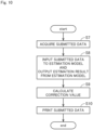
- Fig. 10 is a flow diagram showing a procedure for the printing process.
- the submitted data D1 to be printed is initially acquired (Step S7; a data acquisition step), as shown in Fig. 10 .
- the data acquisition part 41 reads the submitted data D1 from the server 2. Then, the data acquisition part 41 inputs the submitted data D1 to the estimation part 44 and the operation control part 46.
- the estimation part 44 inputs the submitted data D 1 to the estimation model M generated by the learning part 43. Then, the estimation model M outputs the estimation result D5 of the expansion/contraction state of the base material 9 (Step S8; an estimation step).
- the estimation result D5 indicates an estimated value of the expansion/contraction state of the base material 9 resulting from inks when the submitted data D1 is printed in the printing apparatus 1.
- the estimation part 44 outputs the obtained estimation result D5 to the correction value calculation part 45.
- the correction value calculation part 45 calculates the correction value D6, based on the estimation result D5 outputted from the estimation part 44 (Step S9).
- This correction value D6 is a control value for fine adjustment of the ejection position of ink droplets onto the base material 9.
- the correction value calculation part 45 sets the correction value D6 in a direction for canceling the expansion/contraction state of the base material 9 indicated by the estimation result D5. For example, if a portion of the base material 9 is estimated to be displaced toward one side in the width direction thereof due to the expansion and contraction of the base material 9, the correction value calculation part 45 calculates the correction value D6 so that the ejection position of ink droplets is corrected toward the other side in the width direction. Then, the correction value calculation part 45 inputs the calculated correction value D6 to the operation control part 46.
- the operation control part 46 controls the operations of the transport mechanism 10 and the four heads 21 to 24, based on the submitted data D1 acquired from the data acquisition part 41 and the correction value D6 acquired from the correction value calculation part 45. In this process, the operation control part 46 corrects the ink ejection position specified by the submitted data D1 in accordance with the correction value D6. This correction is made, for example, for each pixel of the submitted data D1. Then, ink droplets are ejected at the corrected ejection position on the printing surface of the base material 9. Thus, the submitted data D1 is printed on the printing surface of the base material 9 (Step S10; a printing step).
- the printing apparatus 1 estimates the expansion/contraction state of the base material 9 resulting from inks, based on the submitted data D1, prior to the printing of the submitted data D1.
- the printing apparatus 1 is capable of ejecting ink droplets onto the printing surface of the base material 9 while correcting the ink ejection position in consideration of the estimation result.
- the printing apparatus 1 provides high-quality printed products with less distortion of the printed image and with less misregistration.
- the grid marks 52 are arranged in equally spaced apart relation in the learning data D2.
- the grid marks 52 need not necessarily be equally spaced apart from each other.
- the grid marks 52 may be arranged more densely in a portion of the image 51 where a change in density value or in coverage rate is larger than in other portions thereof.
- each of the grid marks 52 is comprised of the white base figure 521 and the black mark figure 522.
- the color of the base figure 521 is not necessarily limited to white.
- the color of the mark figure 522 is not necessarily limited to black.
- the base figure 521 may be black and the mark figure 522 may be white.
- the base figure 521 and the mark figure 522 may also be of other colors. It is only necessary that each of the grid marks 52 is comprised of the base figure 521 of a first color and the mark figure 522 of a second color different from the first color.
- the shapes of the base figure 521 and the mark figure 522 may be different from those of the aforementioned preferred embodiment.
- the only information inputted to the estimation model M in the learning process is the learning data D2.
- additional information such as detected values from various sensors in the printing apparatus 1 and the type of the base material 9 in addition to the learning data D2 may be inputted to the estimation model M.
- the aforementioned additional information in addition to the submitted data D1 may be inputted to the estimation model M in the printing process. This allows the estimation model M to output the estimation result D5 with higher accuracy in consideration of the additional information.
- the expansion/contraction state of the base material 9 is estimated based on the estimation model M generated by machine learning.
- the expansion/contraction state of the base material 9 may be estimated by other methods. For example, a relationship between the density value or coverage rate of each region included in the submitted data D1 and the expansion/contraction state of the base material 9 may be formulated. Also, a correspondence relationship between the density value or coverage rate of each region included in the submitted data D1 and the expansion/contraction state of the base material 9 may be specified using a table. Then, prior to the printing of the submitted data D1, an estimation result indicating the expansion/contraction state of the base material 9 may be outputted based on the submitted data D1 and the aforementioned formula or table.
- the formula or table is used, it is necessary to modify the formula or table each time the state of the printing apparatus 1 or the type of the base material 9 is changed. This process of modifying the formula or table places a heavy burden on a user because consideration is required from various viewpoints.
- the use of machine learning as in the aforementioned preferred embodiment allows the estimation model M to be re-created by performing a certain learning process even when the state of the printing apparatus 1 or the type of the base material 9 is changed.
- the aforementioned preferred embodiment is capable of easily responding to changes in conditions.
- the nozzles 201 are arranged in a line in the width direction in each of the heads 21 to 24.
- the nozzles 201 may be arranged in two or more lines in each of the heads 21 to 24 as shown in Fig. 2 .
- the printing apparatus 1 of the aforementioned preferred embodiment includes the four heads 21 to 24.
- the number of heads in the printing apparatus 1 may be in the range of one to three or not less than five.
- the printing apparatus 1 may include a head for ejecting ink of a spot color in addition to those for K, C, M and Y.
Landscapes
- Engineering & Computer Science (AREA)
- Physics & Mathematics (AREA)
- Theoretical Computer Science (AREA)
- Life Sciences & Earth Sciences (AREA)
- Computing Systems (AREA)
- Mathematical Physics (AREA)
- Biophysics (AREA)
- Computational Linguistics (AREA)
- Data Mining & Analysis (AREA)
- Evolutionary Computation (AREA)
- General Health & Medical Sciences (AREA)
- Molecular Biology (AREA)
- Artificial Intelligence (AREA)
- General Engineering & Computer Science (AREA)
- General Physics & Mathematics (AREA)
- Biomedical Technology (AREA)
- Software Systems (AREA)
- Health & Medical Sciences (AREA)
- Chemical & Material Sciences (AREA)
- Quality & Reliability (AREA)
- Materials Engineering (AREA)
- Wood Science & Technology (AREA)
- Organic Chemistry (AREA)
- Ink Jet (AREA)
- Handling Of Sheets (AREA)
- Accessory Devices And Overall Control Thereof (AREA)
Claims (12)
- Verfahren zum Abschätzen des Expansions-/Kontraktionszustands eines netzartigen Basismaterials (9) in einer Druckvorrichtung (1), die Tinte auf eine Oberfläche des Basismaterials (9) ausstößt, während sie das Basismaterial (9) in einer Längsrichtung desselben transportiert, wobei Verfahren die Schritte umfasst:a) Erfassen übermittelter Daten (D1), die zu druckende Bilddaten sind; undb) Ausgeben eines Abschätzergebnisses (D5) basierend auf den übermittelten Daten (D1), das den Ausdehnungs-/Kontraktionszustand des Basismaterials (9) anzeigt, der sich aus der Tinte ergibt, wenn die übermittelten Daten (D1) gedruckt werden, vor dem Drucken der übermittelten Daten (D1), dadurch gekennzeichnet, dassdas Abschätzergebnis (D5) durch Abschätzen einer Verteilung von Ausdehnungs-/Kontraktionsbeträgen auf dem Basismaterial (9) erhalten wird.
- Verfahren gemäß Anspruch 1, ferner umfassend den Schrittc) Generieren eines Abschätzmodells (M), das den Ausdehnungs-/Kontraktionszustand des Basismaterials (9) mittels maschinellen Lernens unter Verwendung von Lerndaten (D2) abschätzen kann, die Bilddaten zum Lernen als eine Eingangsvariable und der Ausdehnungs-/Kontraktionszustand (D4) des Basismaterials (9) zum Zeitpunkt des Druckens der Lerndaten (D2) in der Druckvorrichtung (1) als Lehrerdaten sind,wobei die übermittelten Daten (D1) in das Abschätzmodell (M) eingegeben werden und der von dem Abschätzmodelll (M) ausgegebene Expansions- /Kontraktionszustand als das Abschätzergebnis (D5) in dem Schritt b) verwendet wird, undder Ausdehnungs-/Kontraktionszustand (D4) durch Messen einer Verteilung der Ausdehnungs-/Kontraktionsbeträge auf dem Basismaterial (9) erhalten wird.
- Verfahren gemäß Anspruch 2,wobei die Lerndaten (D2) Bilddaten sind, in denen eine Vielzahl von beabstandet angeordneten Markierungen (52) enthalten sind, undwobei der Ausdehnungs-/Kontraktionszustand (D4), der zu den Lehrerdaten wird, in dem Schritt c) basierend auf den Positionen der Markierungen (52) auf dem Basismaterial (9) zum Zeitpunkt des Druckens der Lerndaten (D2) in der Druckvorrichtung (1) gemessen wird.
- Verfahren gemäß Anspruch 3,
wobei jede der Markierungen (52) umfasst:eine Basisfigur (521) einer ersten Farbe; undeine Markierungsfigur (522) einer zweiten Farbe, die sich von der ersten Farbe unterscheidet, wobei sich die Markierungsfigur (522) in einer Position befindet, die die Basisfigur (521) überlagert. - Verfahren gemäß Anspruch 4,
wobei die erste Farbe weiß ist und die zweite Farbe schwarz ist. - Verfahren gemäß einem der Ansprüche 3 bis 5,
wobei die Lehrerdaten eine Änderung des Abstands zwischen benachbarten Markierungen (52) anzeigen. - Verfahren gemäß einem der Ansprüche 3 bis 5,
wobei die Lehrerdaten den Betrag der Verschiebung jeder der Markierungen (52) anzeigen. - Verfahren gemäß einem der Ansprüche 2 bis 7,
wobei die Lerndaten (D2) Bilddaten sind, die eine Vielzahl von Bereichen mit unterschiedlichem Dichtewert oder Deckungsgrad enthalten. - Verfahren zum Drucken unter Verwendung des Abschätzverfahrens gemäß einem der Ansprüche 1 bis 8, ferner umfassend den folgenden Schritt
d) Ausstoßen von Tinte auf die Oberfläche des Basismaterials (9), während die Ausstoßposition der Tinte auf das Basismaterial (9) basierend auf dem Abschätzergebnis (D5) korrigiert wird, wobei der Schritt d) nach den Schritten a) und b) durchgeführt wird. - Druckvorrichtung (1) umfassend:einen Datenerfassungsteil (41) zum Erfassen von übermittelten Daten (D1), die zu druckende Bilddaten sind;einen Transportmechanismus (10) zum Transportieren eines netzartigen Basismaterials (9) entlang eines vorbestimmten Transportweges in einer Längsrichtung desselben;einen Kopf (21-24) zum Ausstoßen von Tinte auf eine Oberfläche des Basismaterials (9), das von dem Transportmechanismus (10) transportiert wird, basierend auf den übermittelten Daten (D1), undeinen Abschätzteil (44) zum Ausgeben eines Abschätzergebnisses (D5) basierend auf den übermittelten Daten (D1), das den Ausdehnungs-/Kontraktionszustand des Basismaterials (9) anzeigt, der sich aus der Tine ergibt, wenn die übermittelten Daten (D1) gedruckt werden, vor dem Drucken der übermittelten Daten (D1), dadurch gekennzeichnet, dassdas Abschätzergebnis (D5) durch Abschätzen einer Verteilung von Ausdehnungs-/Kontraktionsbeträgen auf dem Basismaterial (9) erhalten wird.
- Druckvorrichtung (1) gemäß Anspruch 10, ferner umfassend:eine Kamera (30) zum Fotografieren einer Druckoberfläche des Basismaterials (9) in einer Position stromabwärts des Kopfes (21-24) entlang des Transportweges;einen Ausdehnungs-/Kontraktionszustandsmessteil (42) zum Messen des Ausdehnungs-/Kontraktionszustands (D4) des Basismaterials (9), basierend auf einem fotografischen Bild (D3) von der Kamera (30); undeinen Lernteil (43) zum Erzeugen eines Abschätzmodells (M), das den Ausdehnungs-/Kontraktionszustand des Basismaterials (9) mittels maschinellen Lernens unter Verwendung von Lerndaten (D2) abschätzen kann, die Bilddaten zum Lernen als Eingangsvariable und der Ausdehnungs-/Kontraktionszustands (D4) zum Zeitpunkt des Druckens der Lerndaten (D2) als Lehrerdaten sind,wobei der Abschätzteil (44) die übermittelten Daten (D1) in das Abschätzmodell (M) eingibt und den von dem Abschätzmodell (M) ausgegebenen Expansions- /Kontraktionszustand als das Abschätzergebnis (D5) verwendet, undder Ausdehnungs-/Kontraktionszustand (D4) durch Messen einer Verteilung der Ausdehnungs-/Kontraktionsbeträge auf dem Basismaterial (9) erhalten wird.
- Druckvorrichtung (1) gemäß Anspruch 10 oder 11, ferner umfassend:einen Korrekturwert-Berechnungsteil (45) zum Berechnen eines Korrekturwertes (D6) basierend auf dem Abschätzergebnis (D5); undeinen Betriebssteuerteil (46) zum Steuern des Transportmechanismus (10) und des Kopfes (21-24) derart, dass die Tinte auf die Oberfläche des Basismaterials (9) ausgestoßen wird, während die Ausstoßposition der Tinte auf das Basismaterial (9) basierend auf dem Korrekturwert (D6) korrigiert wird.
Applications Claiming Priority (1)
| Application Number | Priority Date | Filing Date | Title |
|---|---|---|---|
| JP2021006154A JP7602380B2 (ja) | 2021-01-19 | 2021-01-19 | 推定方法、印刷方法、および印刷装置 |
Publications (2)
| Publication Number | Publication Date |
|---|---|
| EP4029697A1 EP4029697A1 (de) | 2022-07-20 |
| EP4029697B1 true EP4029697B1 (de) | 2024-07-31 |
Family
ID=78957608
Family Applications (1)
| Application Number | Title | Priority Date | Filing Date |
|---|---|---|---|
| EP21216278.8A Active EP4029697B1 (de) | 2021-01-19 | 2021-12-21 | Schätzverfahren, druckverfahren und druckvorrichtung |
Country Status (3)
| Country | Link |
|---|---|
| US (1) | US20220227126A1 (de) |
| EP (1) | EP4029697B1 (de) |
| JP (1) | JP7602380B2 (de) |
Families Citing this family (4)
| Publication number | Priority date | Publication date | Assignee | Title |
|---|---|---|---|---|
| JP7775705B2 (ja) * | 2021-12-27 | 2025-11-26 | 株式会社リコー | 液体吐出装置及び液体吐出方法 |
| KR102915938B1 (ko) * | 2022-10-17 | 2026-01-21 | 한국기계연구원 | 인공지능을 이용한 스크린 프린팅 패턴 학습 및 보정 방법과 이를 수행하는 시스템 및 프로그램 |
| JP2024110603A (ja) | 2023-02-03 | 2024-08-16 | 株式会社Screenホールディングス | マーク検出方法、歪み量測定方法、学習方法、推定方法、および印刷方法 |
| JP2024139123A (ja) * | 2023-03-27 | 2024-10-09 | 株式会社Screenホールディングス | 推定方法、印刷方法、および印刷装置 |
Family Cites Families (11)
| Publication number | Priority date | Publication date | Assignee | Title |
|---|---|---|---|---|
| JP5201846B2 (ja) * | 2007-02-16 | 2013-06-05 | キヤノン株式会社 | インクジェット記録装置および該装置の制御方法 |
| US8300266B2 (en) * | 2009-03-12 | 2012-10-30 | Xerox Corporation | System and method for adjusting operation of printheads in an ink printing device |
| JP5503952B2 (ja) | 2009-12-09 | 2014-05-28 | 富士フイルム株式会社 | 印刷装置及び印刷制御方法 |
| JP2012183727A (ja) | 2011-03-07 | 2012-09-27 | Olympus Corp | 画像記録装置及びその制御方法 |
| US8960846B2 (en) | 2012-07-11 | 2015-02-24 | Hewlett-Packard Industrial Printing Ltd. | Printer and method for inkjet printing on a flexible substrate |
| JP6149563B2 (ja) | 2013-07-12 | 2017-06-21 | 株式会社リコー | 画像形成装置、画像形成制御方法及び画像形成制御プログラム |
| JP6262964B2 (ja) | 2013-09-02 | 2018-01-17 | 株式会社Screenホールディングス | 画像記録装置および画像記録方法 |
| JP6521592B2 (ja) * | 2014-08-25 | 2019-05-29 | キヤノン株式会社 | 記録装置及びその制御方法、プログラム、記憶媒体 |
| JP6265502B2 (ja) * | 2015-03-18 | 2018-01-24 | 富士フイルム株式会社 | 透明液吐出量決定装置及び方法、並びに画像形成装置及び方法 |
| WO2019192867A1 (en) * | 2018-04-04 | 2019-10-10 | OCE Holding B.V. | Duplex printing method with shrinkage compensation |
| JP2020164321A (ja) * | 2019-03-29 | 2020-10-08 | 株式会社Screenホールディングス | 基材処理装置および基材処理方法 |
-
2021
- 2021-01-19 JP JP2021006154A patent/JP7602380B2/ja active Active
- 2021-11-22 US US17/532,327 patent/US20220227126A1/en not_active Abandoned
- 2021-12-21 EP EP21216278.8A patent/EP4029697B1/de active Active
Also Published As
| Publication number | Publication date |
|---|---|
| US20220227126A1 (en) | 2022-07-21 |
| JP2022110632A (ja) | 2022-07-29 |
| JP7602380B2 (ja) | 2024-12-18 |
| EP4029697A1 (de) | 2022-07-20 |
Similar Documents
| Publication | Publication Date | Title |
|---|---|---|
| EP4029697B1 (de) | Schätzverfahren, druckverfahren und druckvorrichtung | |
| US8223351B2 (en) | Method and system for continuous feed printing systems | |
| EP3017956B1 (de) | Vorrichtung und verfahren zur bildaufzeichnung | |
| EP3202579B1 (de) | Thermotransferdrucker und druckverfahren damit | |
| JP2021146510A (ja) | 学習方法、制御方法、および印刷装置 | |
| JP7449732B2 (ja) | 異常検知方法および搬送装置 | |
| JP2007320240A (ja) | 画像記録装置及び画像記録方法 | |
| WO2023068026A1 (ja) | 印刷装置および管理方法 | |
| EP3461115B1 (de) | Tintenstrahldruckvorrichtung und korrekturverfahren für variable dichte | |
| JP7691317B2 (ja) | 検出方法、学習方法、推定方法、印刷方法、および検出装置 | |
| CN117581527A (zh) | 用于颜色校正数字印刷机的方法 | |
| JP7397731B2 (ja) | 調整方法および印刷装置 | |
| EP4660114A1 (de) | Markierungserkennungsverfahren, verzerrungsmengenmessverfahren, lernverfahren, schätzverfahren und druckverfahren | |
| JP6900409B2 (ja) | 印刷装置 | |
| JP2022122676A (ja) | 搬送装置、処理装置、搬送方法、および処理方法 | |
| EP2610063B1 (de) | Tinten-Bildaufzeichnungsvorrichtung | |
| US12420546B2 (en) | Image formation apparatus and method of forming an image | |
| US11093808B2 (en) | Color matching method, and recording medium having color matching program recorded thereon | |
| US9463651B2 (en) | Inkjet printer, method of controlling inkjet printer and computer program | |
| JP7460517B2 (ja) | 印刷装置および管理方法 | |
| JP5883313B2 (ja) | 画像記録装置、補正係数取得方法および画像記録方法 | |
| WO2024202451A1 (ja) | 推定方法、印刷方法、および印刷装置 | |
| US12132876B2 (en) | Imaging device | |
| US20130135642A1 (en) | Image processing apparatus and image processing method | |
| US20250074071A1 (en) | Printing apparatus and print control method |
Legal Events
| Date | Code | Title | Description |
|---|---|---|---|
| PUAI | Public reference made under article 153(3) epc to a published international application that has entered the european phase |
Free format text: ORIGINAL CODE: 0009012 |
|
| STAA | Information on the status of an ep patent application or granted ep patent |
Free format text: STATUS: THE APPLICATION HAS BEEN PUBLISHED |
|
| AK | Designated contracting states |
Kind code of ref document: A1 Designated state(s): AL AT BE BG CH CY CZ DE DK EE ES FI FR GB GR HR HU IE IS IT LI LT LU LV MC MK MT NL NO PL PT RO RS SE SI SK SM TR |
|
| STAA | Information on the status of an ep patent application or granted ep patent |
Free format text: STATUS: REQUEST FOR EXAMINATION WAS MADE |
|
| 17P | Request for examination filed |
Effective date: 20230120 |
|
| RBV | Designated contracting states (corrected) |
Designated state(s): AL AT BE BG CH CY CZ DE DK EE ES FI FR GB GR HR HU IE IS IT LI LT LU LV MC MK MT NL NO PL PT RO RS SE SI SK SM TR |
|
| GRAP | Despatch of communication of intention to grant a patent |
Free format text: ORIGINAL CODE: EPIDOSNIGR1 |
|
| STAA | Information on the status of an ep patent application or granted ep patent |
Free format text: STATUS: GRANT OF PATENT IS INTENDED |
|
| INTG | Intention to grant announced |
Effective date: 20240229 |
|
| GRAS | Grant fee paid |
Free format text: ORIGINAL CODE: EPIDOSNIGR3 |
|
| GRAA | (expected) grant |
Free format text: ORIGINAL CODE: 0009210 |
|
| STAA | Information on the status of an ep patent application or granted ep patent |
Free format text: STATUS: THE PATENT HAS BEEN GRANTED |
|
| P01 | Opt-out of the competence of the unified patent court (upc) registered |
Effective date: 20240524 |
|
| AK | Designated contracting states |
Kind code of ref document: B1 Designated state(s): AL AT BE BG CH CY CZ DE DK EE ES FI FR GB GR HR HU IE IS IT LI LT LU LV MC MK MT NL NO PL PT RO RS SE SI SK SM TR |
|
| REG | Reference to a national code |
Ref country code: CH Ref legal event code: EP Ref country code: GB Ref legal event code: FG4D |
|
| REG | Reference to a national code |
Ref country code: DE Ref legal event code: R096 Ref document number: 602021016442 Country of ref document: DE |
|
| REG | Reference to a national code |
Ref country code: IE Ref legal event code: FG4D |
|
| REG | Reference to a national code |
Ref country code: LT Ref legal event code: MG9D |
|
| REG | Reference to a national code |
Ref country code: NL Ref legal event code: MP Effective date: 20240731 |
|
| PG25 | Lapsed in a contracting state [announced via postgrant information from national office to epo] |
Ref country code: PT Free format text: LAPSE BECAUSE OF FAILURE TO SUBMIT A TRANSLATION OF THE DESCRIPTION OR TO PAY THE FEE WITHIN THE PRESCRIBED TIME-LIMIT Effective date: 20241202 |
|
| REG | Reference to a national code |
Ref country code: AT Ref legal event code: MK05 Ref document number: 1708129 Country of ref document: AT Kind code of ref document: T Effective date: 20240731 |
|
| PG25 | Lapsed in a contracting state [announced via postgrant information from national office to epo] |
Ref country code: PT Free format text: LAPSE BECAUSE OF FAILURE TO SUBMIT A TRANSLATION OF THE DESCRIPTION OR TO PAY THE FEE WITHIN THE PRESCRIBED TIME-LIMIT Effective date: 20241202 |
|
| PG25 | Lapsed in a contracting state [announced via postgrant information from national office to epo] |
Ref country code: NO Free format text: LAPSE BECAUSE OF FAILURE TO SUBMIT A TRANSLATION OF THE DESCRIPTION OR TO PAY THE FEE WITHIN THE PRESCRIBED TIME-LIMIT Effective date: 20241031 |
|
| PG25 | Lapsed in a contracting state [announced via postgrant information from national office to epo] |
Ref country code: NL Free format text: LAPSE BECAUSE OF FAILURE TO SUBMIT A TRANSLATION OF THE DESCRIPTION OR TO PAY THE FEE WITHIN THE PRESCRIBED TIME-LIMIT Effective date: 20240731 Ref country code: GR Free format text: LAPSE BECAUSE OF FAILURE TO SUBMIT A TRANSLATION OF THE DESCRIPTION OR TO PAY THE FEE WITHIN THE PRESCRIBED TIME-LIMIT Effective date: 20241101 Ref country code: PL Free format text: LAPSE BECAUSE OF FAILURE TO SUBMIT A TRANSLATION OF THE DESCRIPTION OR TO PAY THE FEE WITHIN THE PRESCRIBED TIME-LIMIT Effective date: 20240731 Ref country code: FI Free format text: LAPSE BECAUSE OF FAILURE TO SUBMIT A TRANSLATION OF THE DESCRIPTION OR TO PAY THE FEE WITHIN THE PRESCRIBED TIME-LIMIT Effective date: 20240731 |
|
| PG25 | Lapsed in a contracting state [announced via postgrant information from national office to epo] |
Ref country code: BG Free format text: LAPSE BECAUSE OF FAILURE TO SUBMIT A TRANSLATION OF THE DESCRIPTION OR TO PAY THE FEE WITHIN THE PRESCRIBED TIME-LIMIT Effective date: 20240731 |
|
| PG25 | Lapsed in a contracting state [announced via postgrant information from national office to epo] |
Ref country code: LV Free format text: LAPSE BECAUSE OF FAILURE TO SUBMIT A TRANSLATION OF THE DESCRIPTION OR TO PAY THE FEE WITHIN THE PRESCRIBED TIME-LIMIT Effective date: 20240731 |
|
| PG25 | Lapsed in a contracting state [announced via postgrant information from national office to epo] |
Ref country code: IS Free format text: LAPSE BECAUSE OF FAILURE TO SUBMIT A TRANSLATION OF THE DESCRIPTION OR TO PAY THE FEE WITHIN THE PRESCRIBED TIME-LIMIT Effective date: 20241130 Ref country code: AT Free format text: LAPSE BECAUSE OF FAILURE TO SUBMIT A TRANSLATION OF THE DESCRIPTION OR TO PAY THE FEE WITHIN THE PRESCRIBED TIME-LIMIT Effective date: 20240731 |
|
| PG25 | Lapsed in a contracting state [announced via postgrant information from national office to epo] |
Ref country code: HR Free format text: LAPSE BECAUSE OF FAILURE TO SUBMIT A TRANSLATION OF THE DESCRIPTION OR TO PAY THE FEE WITHIN THE PRESCRIBED TIME-LIMIT Effective date: 20240731 |
|
| PG25 | Lapsed in a contracting state [announced via postgrant information from national office to epo] |
Ref country code: ES Free format text: LAPSE BECAUSE OF FAILURE TO SUBMIT A TRANSLATION OF THE DESCRIPTION OR TO PAY THE FEE WITHIN THE PRESCRIBED TIME-LIMIT Effective date: 20240731 Ref country code: RS Free format text: LAPSE BECAUSE OF FAILURE TO SUBMIT A TRANSLATION OF THE DESCRIPTION OR TO PAY THE FEE WITHIN THE PRESCRIBED TIME-LIMIT Effective date: 20241031 |
|
| PG25 | Lapsed in a contracting state [announced via postgrant information from national office to epo] |
Ref country code: RS Free format text: LAPSE BECAUSE OF FAILURE TO SUBMIT A TRANSLATION OF THE DESCRIPTION OR TO PAY THE FEE WITHIN THE PRESCRIBED TIME-LIMIT Effective date: 20241031 Ref country code: PL Free format text: LAPSE BECAUSE OF FAILURE TO SUBMIT A TRANSLATION OF THE DESCRIPTION OR TO PAY THE FEE WITHIN THE PRESCRIBED TIME-LIMIT Effective date: 20240731 Ref country code: NO Free format text: LAPSE BECAUSE OF FAILURE TO SUBMIT A TRANSLATION OF THE DESCRIPTION OR TO PAY THE FEE WITHIN THE PRESCRIBED TIME-LIMIT Effective date: 20241031 Ref country code: NL Free format text: LAPSE BECAUSE OF FAILURE TO SUBMIT A TRANSLATION OF THE DESCRIPTION OR TO PAY THE FEE WITHIN THE PRESCRIBED TIME-LIMIT Effective date: 20240731 Ref country code: LV Free format text: LAPSE BECAUSE OF FAILURE TO SUBMIT A TRANSLATION OF THE DESCRIPTION OR TO PAY THE FEE WITHIN THE PRESCRIBED TIME-LIMIT Effective date: 20240731 Ref country code: IS Free format text: LAPSE BECAUSE OF FAILURE TO SUBMIT A TRANSLATION OF THE DESCRIPTION OR TO PAY THE FEE WITHIN THE PRESCRIBED TIME-LIMIT Effective date: 20241130 Ref country code: HR Free format text: LAPSE BECAUSE OF FAILURE TO SUBMIT A TRANSLATION OF THE DESCRIPTION OR TO PAY THE FEE WITHIN THE PRESCRIBED TIME-LIMIT Effective date: 20240731 Ref country code: GR Free format text: LAPSE BECAUSE OF FAILURE TO SUBMIT A TRANSLATION OF THE DESCRIPTION OR TO PAY THE FEE WITHIN THE PRESCRIBED TIME-LIMIT Effective date: 20241101 Ref country code: FI Free format text: LAPSE BECAUSE OF FAILURE TO SUBMIT A TRANSLATION OF THE DESCRIPTION OR TO PAY THE FEE WITHIN THE PRESCRIBED TIME-LIMIT Effective date: 20240731 Ref country code: ES Free format text: LAPSE BECAUSE OF FAILURE TO SUBMIT A TRANSLATION OF THE DESCRIPTION OR TO PAY THE FEE WITHIN THE PRESCRIBED TIME-LIMIT Effective date: 20240731 Ref country code: BG Free format text: LAPSE BECAUSE OF FAILURE TO SUBMIT A TRANSLATION OF THE DESCRIPTION OR TO PAY THE FEE WITHIN THE PRESCRIBED TIME-LIMIT Effective date: 20240731 Ref country code: AT Free format text: LAPSE BECAUSE OF FAILURE TO SUBMIT A TRANSLATION OF THE DESCRIPTION OR TO PAY THE FEE WITHIN THE PRESCRIBED TIME-LIMIT Effective date: 20240731 |
|
| PG25 | Lapsed in a contracting state [announced via postgrant information from national office to epo] |
Ref country code: RO Free format text: LAPSE BECAUSE OF FAILURE TO SUBMIT A TRANSLATION OF THE DESCRIPTION OR TO PAY THE FEE WITHIN THE PRESCRIBED TIME-LIMIT Effective date: 20240731 Ref country code: DK Free format text: LAPSE BECAUSE OF FAILURE TO SUBMIT A TRANSLATION OF THE DESCRIPTION OR TO PAY THE FEE WITHIN THE PRESCRIBED TIME-LIMIT Effective date: 20240731 Ref country code: SM Free format text: LAPSE BECAUSE OF FAILURE TO SUBMIT A TRANSLATION OF THE DESCRIPTION OR TO PAY THE FEE WITHIN THE PRESCRIBED TIME-LIMIT Effective date: 20240731 |
|
| PG25 | Lapsed in a contracting state [announced via postgrant information from national office to epo] |
Ref country code: EE Free format text: LAPSE BECAUSE OF FAILURE TO SUBMIT A TRANSLATION OF THE DESCRIPTION OR TO PAY THE FEE WITHIN THE PRESCRIBED TIME-LIMIT Effective date: 20240731 |
|
| PG25 | Lapsed in a contracting state [announced via postgrant information from national office to epo] |
Ref country code: CZ Free format text: LAPSE BECAUSE OF FAILURE TO SUBMIT A TRANSLATION OF THE DESCRIPTION OR TO PAY THE FEE WITHIN THE PRESCRIBED TIME-LIMIT Effective date: 20240731 |
|
| PG25 | Lapsed in a contracting state [announced via postgrant information from national office to epo] |
Ref country code: IT Free format text: LAPSE BECAUSE OF FAILURE TO SUBMIT A TRANSLATION OF THE DESCRIPTION OR TO PAY THE FEE WITHIN THE PRESCRIBED TIME-LIMIT Effective date: 20240731 Ref country code: SK Free format text: LAPSE BECAUSE OF FAILURE TO SUBMIT A TRANSLATION OF THE DESCRIPTION OR TO PAY THE FEE WITHIN THE PRESCRIBED TIME-LIMIT Effective date: 20240731 |
|
| REG | Reference to a national code |
Ref country code: DE Ref legal event code: R097 Ref document number: 602021016442 Country of ref document: DE |
|
| PLBE | No opposition filed within time limit |
Free format text: ORIGINAL CODE: 0009261 |
|
| STAA | Information on the status of an ep patent application or granted ep patent |
Free format text: STATUS: NO OPPOSITION FILED WITHIN TIME LIMIT |
|
| PG25 | Lapsed in a contracting state [announced via postgrant information from national office to epo] |
Ref country code: MC Free format text: LAPSE BECAUSE OF FAILURE TO SUBMIT A TRANSLATION OF THE DESCRIPTION OR TO PAY THE FEE WITHIN THE PRESCRIBED TIME-LIMIT Effective date: 20240731 |
|
| 26N | No opposition filed |
Effective date: 20250501 |
|
| REG | Reference to a national code |
Ref country code: CH Ref legal event code: PL |
|
| PG25 | Lapsed in a contracting state [announced via postgrant information from national office to epo] |
Ref country code: LU Free format text: LAPSE BECAUSE OF NON-PAYMENT OF DUE FEES Effective date: 20241221 |
|
| PG25 | Lapsed in a contracting state [announced via postgrant information from national office to epo] |
Ref country code: SE Free format text: LAPSE BECAUSE OF FAILURE TO SUBMIT A TRANSLATION OF THE DESCRIPTION OR TO PAY THE FEE WITHIN THE PRESCRIBED TIME-LIMIT Effective date: 20240731 |
|
| REG | Reference to a national code |
Ref country code: BE Ref legal event code: MM Effective date: 20241231 |
|
| PG25 | Lapsed in a contracting state [announced via postgrant information from national office to epo] |
Ref country code: BE Free format text: LAPSE BECAUSE OF NON-PAYMENT OF DUE FEES Effective date: 20241231 |
|
| PG25 | Lapsed in a contracting state [announced via postgrant information from national office to epo] |
Ref country code: CH Free format text: LAPSE BECAUSE OF NON-PAYMENT OF DUE FEES Effective date: 20241231 |
|
| PG25 | Lapsed in a contracting state [announced via postgrant information from national office to epo] |
Ref country code: IE Free format text: LAPSE BECAUSE OF NON-PAYMENT OF DUE FEES Effective date: 20241221 |
|
| PGFP | Annual fee paid to national office [announced via postgrant information from national office to epo] |
Ref country code: DE Payment date: 20251028 Year of fee payment: 5 |
|
| PGFP | Annual fee paid to national office [announced via postgrant information from national office to epo] |
Ref country code: GB Payment date: 20251030 Year of fee payment: 5 |
|
| PGFP | Annual fee paid to national office [announced via postgrant information from national office to epo] |
Ref country code: FR Payment date: 20251110 Year of fee payment: 5 |