EP4028757B1 - Glasfaserverteilungsmesssystem und signalverarbeitungsverfahren zur messung der glasfaserverteilung - Google Patents
Glasfaserverteilungsmesssystem und signalverarbeitungsverfahren zur messung der glasfaserverteilung Download PDFInfo
- Publication number
- EP4028757B1 EP4028757B1 EP20862088.0A EP20862088A EP4028757B1 EP 4028757 B1 EP4028757 B1 EP 4028757B1 EP 20862088 A EP20862088 A EP 20862088A EP 4028757 B1 EP4028757 B1 EP 4028757B1
- Authority
- EP
- European Patent Office
- Prior art keywords
- signal
- laser
- optical fiber
- light
- phase
- Prior art date
- Legal status (The legal status is an assumption and is not a legal conclusion. Google has not performed a legal analysis and makes no representation as to the accuracy of the status listed.)
- Active
Links
Images




Classifications
-
- G—PHYSICS
- G01—MEASURING; TESTING
- G01N—INVESTIGATING OR ANALYSING MATERIALS BY DETERMINING THEIR CHEMICAL OR PHYSICAL PROPERTIES
- G01N29/00—Investigating or analysing materials by the use of ultrasonic, sonic or infrasonic waves; Visualisation of the interior of objects by transmitting ultrasonic or sonic waves through the object
- G01N29/04—Analysing solids
-
- G—PHYSICS
- G01—MEASURING; TESTING
- G01N—INVESTIGATING OR ANALYSING MATERIALS BY DETERMINING THEIR CHEMICAL OR PHYSICAL PROPERTIES
- G01N29/00—Investigating or analysing materials by the use of ultrasonic, sonic or infrasonic waves; Visualisation of the interior of objects by transmitting ultrasonic or sonic waves through the object
- G01N29/22—Details, e.g. general constructional or apparatus details
- G01N29/24—Probes
- G01N29/2418—Probes using optoacoustic interaction with the material, e.g. laser radiation, photoacoustics
-
- G—PHYSICS
- G01—MEASURING; TESTING
- G01N—INVESTIGATING OR ANALYSING MATERIALS BY DETERMINING THEIR CHEMICAL OR PHYSICAL PROPERTIES
- G01N29/00—Investigating or analysing materials by the use of ultrasonic, sonic or infrasonic waves; Visualisation of the interior of objects by transmitting ultrasonic or sonic waves through the object
- G01N29/44—Processing the detected response signal, e.g. electronic circuits specially adapted therefor
- G01N29/4409—Processing the detected response signal, e.g. electronic circuits specially adapted therefor by comparison
- G01N29/4436—Processing the detected response signal, e.g. electronic circuits specially adapted therefor by comparison with a reference signal
-
- G—PHYSICS
- G01—MEASURING; TESTING
- G01N—INVESTIGATING OR ANALYSING MATERIALS BY DETERMINING THEIR CHEMICAL OR PHYSICAL PROPERTIES
- G01N2291/00—Indexing codes associated with group G01N29/00
- G01N2291/02—Indexing codes associated with the analysed material
- G01N2291/028—Material parameters
- G01N2291/02827—Elastic parameters, strength or force
-
- G—PHYSICS
- G01—MEASURING; TESTING
- G01N—INVESTIGATING OR ANALYSING MATERIALS BY DETERMINING THEIR CHEMICAL OR PHYSICAL PROPERTIES
- G01N2291/00—Indexing codes associated with group G01N29/00
- G01N2291/02—Indexing codes associated with the analysed material
- G01N2291/028—Material parameters
- G01N2291/02881—Temperature
-
- Y—GENERAL TAGGING OF NEW TECHNOLOGICAL DEVELOPMENTS; GENERAL TAGGING OF CROSS-SECTIONAL TECHNOLOGIES SPANNING OVER SEVERAL SECTIONS OF THE IPC; TECHNICAL SUBJECTS COVERED BY FORMER USPC CROSS-REFERENCE ART COLLECTIONS [XRACs] AND DIGESTS
- Y02—TECHNOLOGIES OR APPLICATIONS FOR MITIGATION OR ADAPTATION AGAINST CLIMATE CHANGE
- Y02A—TECHNOLOGIES FOR ADAPTATION TO CLIMATE CHANGE
- Y02A90/00—Technologies having an indirect contribution to adaptation to climate change
- Y02A90/10—Information and communication technologies [ICT] supporting adaptation to climate change, e.g. for weather forecasting or climate simulation
Definitions
- the present disclosure relates to an optical fiber distribution measurement system and a signal processing method for optical fiber distribution measurement.
- DFOS distributed fiber optic sensing
- DAS distributed acoustic sensing
- DTSS distributed temperature and strain sensing
- TW-COTDR tunable wavelength coherent optical time domain reflectometry
- a time gate digital (TGD) method using a single pulse, multiple wavelengths, or a chirp light source has been proposed, and practical records thereof are being accumulated.
- a type using Brillouin scattering light and a type using Rayleigh scattering light are commercially available (see, for example, US8699009 or Non-Patent Literature 1).
- a broad frequency spectrum of an optical fiber is used, and stability is ensured over several years (see, for example, Non-Patent Literature 2).
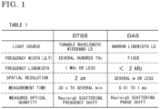
- FIG. 1 shows the details of the features of the above techniques of DAS and DTSS.
- an optical physical quantity to be measured is a Rayleigh scattering frequency shift
- DAS an optical physical quantity to be measured is a Rayleigh scattering phase shift. Due to the above type difference, as compared to the latter measurement method, the former measurement method has a lower spatial resolution and requires a longer measurement time. Thus, there is a difference in performance therebetween.
- a physical quantity to be measured is a Rayleigh scattering phase shift, and therefore it is necessary to measure a phase.
- a phase shift of Rayleigh scattering light occurs by phase noise of a laser diode (hereinafter, abbreviated as LD) itself due to linewidth, and temperature change or strain change affected when an optical fiber is installed at an actual site.
- LD laser diode
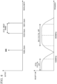
- FIG. 2 illustrates phase change in DAS measurement.
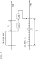
- FIG. 3 shows problems caused in the case of using DAS, for three patterns classified on the basis of component analysis of phase change.
- FIG. 2 shows model graphs illustrating phase change of a signal measured by DAS measurement.
- the graph (the vertical axis indicates signal output and the horizontal axis indicates elapsed time) shown on the upper side in FIG. 2 shows a curve A of the measured phase change, and a curve B obtained by extracting only a long-cycle change part of the curve A.
- the graph shown on the lower side shows, only in a time range from part P (left end time thereof) to part Q (right end time thereof) which are indicated by dotted-line circles in the graph shown on the upper side, a curve C indicating characteristics obtained by subtracting the values corresponding to the respective times in the curve B from the values corresponding to the respective times in the curve A, in which a fast change part of the phase change is specifically shown among others.
- a time range S is obtained by enlarging a time range from the left end time to the right end time of part P in the graph shown on the upper side
- a time range T in the graph shown on the lower side is obtained by enlarging a time range from the left end time to the right end time of part Q in the graph shown on the upper side.
- the curve B is a part that exhibits gradual change over a period such as several ten seconds to several years, in the DAS measurement signal, and this part is considered to be attributable to the influence of temperature change or the like.
- the curve C is a part that exhibits fast change within 10 -5 to 1 [s], in the DAS measurement signal, and this part is considered to be generated by addition of LD phase noise to an acoustic wave signal.
- the first problem is phase noise of the LD, and this problem is to be solved through internal processing in the DAS measurement instrument.
- the second problem is a problem of short-cycle phase change due to, for example, strain at each point of the optical fiber caused by vibration or the like. Regarding addressing of this problem, originally, this problem corresponds to the reason why the DAS measurement is preferentially used, and therefore can be solved by the DAS measurement.
- the third problem is a problem of long-cycle phase change caused by gradual change of temperature or the like. As the measurement is performed during a long period, the DAS measurement performance comes to no longer satisfy the specifications. Therefore, this needs to be eliminated.
- the present disclosure has been made to solve the above problems, and an object of the present disclosure is to provide an optical fiber distribution measurement system and a signal processing method for optical fiber distribution measurement, in which DAS and DTSS based on TW-COTDR are combined, and, using a Rayleigh frequency shift measured by DTSS, a phase value in DAS is corrected at certain intervals longer than a measurement rate in the TW-COTDR method, thereby correcting error due to a Rayleigh scattering light shift which changes with a longer cycle than the DAS measurement rate, thus achieving measurement stability in DAS over a long period.
- the invention is defined by an optical fiber distribution measurement system in accordance with claim 1 and a signal processing method using such a system in accordance with claim 4.
- An optical fiber distribution measurement system includes: a first laser for obtaining a temperature-strain distribution measurement signal through analysis of a frequency shift of Rayleigh scattering light; a second laser for obtaining an elastic wave measurement signal through analysis of a phase shift of Rayleigh scattering light; first to fourth optical couplers for branching or merging laser light; a pulse compression coding circuit including an intensity modulator for modulating an intensity of an optical signal and a phase modulator for modulating a phase of an optical signal, the intensity modulator and the phase modulator being connected in series; an acousto-optic switch for generating pulse light; a circulator for separating optical signals; a calibration optical fiber for generating backscatter light by receiving laser light; a diversity device for combining optical signals to remove noise; a digitizer for converting an input signal to a discrete signal; and a CPU which includes a processor and a storage device and which performs calculation on a signal and performs storage.
- Emitted light from the first laser is branched by the first optical coupler, so as to be inputted to the pulse compression coding circuit and the third optical coupler.
- Emitted light from the second laser is branched by the second optical coupler, so as to be inputted to the acousto-optic switch and the third optical coupler.
- the emitted light from the first laser and the emitted light from the second laser that have been inputted to the third optical coupler are inputted to the diversity device.
- An output signal from the pulse compression coding circuit and an output signal from the acousto-optic switch are merged by the fourth optical coupler, and first backscatter light and second backscatter light generated by the merged output signal being inputted to the calibration optical fiber are inputted via the circulator to the diversity device.
- the first backscatter light, the second backscatter light, the emitted light from the first laser, and the emitted light from the second laser that have undergone signal processing by the diversity device are sent via the digitizer to the CPU so as to be subjected to calculation processing.
- the optical fiber distribution measurement system can obtain a significant effect that it becomes possible to provide an optical fiber distribution measurement system and a signal processing method for optical fiber distribution measurement, in which DAS and DTSS based on TW-COTDR are combined, and, using a Rayleigh frequency shift measured by DTSS, a phase value in DAS is corrected at certain intervals longer than a measurement rate in the TW-COTDR method, thereby correcting error due to a Rayleigh scattering light shift which changes with a longer cycle than the DAS measurement rate, thus achieving measurement stability in DAS over a long period.
- FIG. 4 is a diagram showing an example of a system configuration of an optical fiber distribution measurement system 100 according to embodiment 1.
- Laser light emitted from a tunable wavelength distributed feedback LD 1 (hereinafter, may be referred to as first laser) of TW-COTDR type passes through a first coupler 3a which is an optical device for branching or merging light, to undergo coding processing by a pulse compression coding circuit 4 including an intensity modulator 4a and a phase modulator 4b, and then is inputted to a third coupler 3c.
- the pulse compression coding circuit 4 the laser light is first inputted to the intensity modulator 4a so that the intensity thereof is modulated by the intensity modulator 4a, and then the resultant signal is outputted from the intensity modulator 4a.
- the signal outputted from the intensity modulator 4a is inputted to the phase modulator 4b, the inputted signal is subjected to phase modulation by the phase modulator 4b, and then the resultant signal is outputted. That is, the signal that has undergone coding processing by the pulse compression coding circuit 4 is outputted. Then, the output signal is inputted to a fourth coupler 3d.
- the tunable wavelength distributed feedback LD 1 is a light source in which the wavelength is tunable (1553.5 to 1561.5 nm) over the entire band, and the wavelength range thereof is several tens of nm and the linewidth thereof is 1 MHz.
- an external resonance laser 2 (hereinafter, may be referred to as a second laser) which is a light source for DAS has a fixed wavelength (1550.2 nm), and has a linewidth less than 2 KHz.
- Laser light emitted from the external resonance laser 2 passes through a second coupler 3b, to be inputted to an acousto-optic switch 5 which generates pulse light with high intensity.
- the signal is inputted to the third coupler 3c, and then is inputted to a diversity device 8 which is a device for improving the quality or reliability of the signal by preferentially using an excellent signal or combining received signals to remove noise.
- the diversity device 8 improves the qualities of signals of polarization and phase or improves the reliability thereof.
- the tunable wavelength distributed feedback LD 1 which is a light source of TW-COTDR type and the external resonance laser 2 which is a light source for DAS each require signals for four channels.
- EDFA erbium doped fiber amplifier
- the digitizer 11 for 4CH is connected to a PCI-Express 13 which is a kind of extension bus, e.g., an input/output serial interface shared with a CPU 12 which is a controller.
- FIG. 5 is a diagram illustrating flow of signal processing in the optical fiber distribution measurement system according to embodiment 1.
- the area at the left of a dotted line indicates acquisition, by hardware, of digitizer signals for 4CH (CH1 to CH4) outputted from the digitizer 11 for 4CH provided at the final stage of signal output in constituent components of the optical fiber distribution measurement system shown in FIG. 4 .
- the area at the right of the dotted line indicates the details of data processing by a personal computer (PC) which is shown as the CPU 12 in FIG. 4 .
- PC personal computer
- an upper line indicates a line for analyzing long-term change, i.e., gradual change in physical phenomenon
- a lower line indicates a line for analyzing a short-term physical phenomenon.
- a 100-MHz digital LPF 21 processes, by TW-COTDR, only a low-frequency component of Rayleigh scattering light (frequency) shift components of the digitizer signals 20 for 4CH described above, and a change ⁇ r of this frequency shift component is subjected to correlation analysis 23 over a long period (30 seconds to several minutes), to obtain DTSS output. It is noted that the correlation analysis 23 may be performed over several years, if necessary.
- a random binary code string more specifically, of such binary code strings, a Barker code that minimizes the magnitudes of side lobes of an autocorrelation function described below is used
- a peak time position thereof i.e., time delay
- a delay time shorter than in the case of not dividing the pulse into sub-pulses can be calculated, whereby an effect of improving spatial resolution is obtained.
- the cross-correlation function instead of calculation of the cross-correlation function, calculation of an autocorrelation function of the transmitted signal is performed, whereby the same result can be obtained. That is, in the cross-correlation function, the transmitted signal f(t) (here, t is time) modulated by a random binary code string and a reflection signal reflected by a target are used.
- the peak value of the autocorrelation function is about n times the amplitude of the original pulse signal, the value for S in the S/N ratio increases, and the peak width is 1/n of the original pulse width. That is, an effect of improving both the spatial resolution and the S/N ratio is obtained.
- a Rayleigh scattering light (phase) shift component is subjected to phase analysis 24 in which the processing can be performed in a short period (about 0.5 ms), by DAS, and thus a DAS output signal is obtained.
- calculation of adding the above calculated DTSS signal to the DAS output signal is performed.
- the calculation is performed with signals complementary to each other. That is, it is required that optical signals that are sent from the same optical fiber and have the same phase can be received with the same reception condition and can be processed.
- the device or the data process shown in FIG. 4 and FIG. 5 satisfies the above condition.
- the phase value of the DAS output signal is corrected at regular intervals, whereby a shift amount due to temperature change (due to change in measurement position) in the optical fiber is corrected.
- a shift amount due to temperature change due to change in measurement position
- high-quality output of DAS can be obtained.
- DTSS long-term processing over several years can be performed, and therefore measurement stability in DAS over a long period can also be achieved.
- FIG. 6 clearly illustrates the relationship between the wavelengths of optical outputs set in the system and the frequencies in a reception system, in the DAS measurement and the DTSS measurement described above.
- the wavelength of the optical output in DAS is fixed at 1550.2 nm, whereas the wavelength of the optical output in DTSS is tunable, and the sweep range thereof is 1554.5 nm to 1561.5 nm.
- a digital LPF is used and the cut-off frequency thereof is 100 MHz
- a digital BPF is used and the bandwidth frequency ranges between ⁇ 100 MHz, with the center frequency being 300 MHz.
- a rate T 1 which corresponds to a measurement timing in TW-COTDR, shown in FIG. 7 is about 30 to 60 seconds.
- a change amount ⁇ T due to change in the outside environment such as temperature is calculated, and the calculated change amount ⁇ T is converted to phase.
- the phase is added to the DAS measurement signal that has been measured, shown in the lower part in FIG. 7 , whereby the original measured DAS signal is corrected.
- a DAS rate T 2 which corresponds to a measurement timing in DAS is about 0.5 ms within a time interval Tc (> T 1 ) which corresponds to the correction timing. That is, the time interval Tc for correcting the DAS signal by the DTSS signal is set to be greater than the rate T 1 in TW-COTDR. It is noted that the correction is performed for the entire optical fiber.
- FIG. 8 shows an example of the configuration of a signal processing model in the case of applying the optical fiber distribution measurement system according to embodiment 1 to long-term measurement.
- a DAS measurement pulse corresponds to the DAS rate T 2 shown in FIG. 7 , and is repeatedly outputted at a speed of 2 KHz or higher.
- the measured signal is outputted as a phase signal.
- a DTSS signal obtained by correlation analysis using TW-COTDR during a measurement time A (A is about 30 to 60 seconds) is outputted.
- measurement using TW-COTDR after measurement has been performed n times, measurement is performed m times in total within a measurement time interval B.
- a Rayleigh frequency shift signal ⁇ R of the outputted DTSS signal is converted to a phase amount ⁇ , which is added to the DAS measurement signal, whereby the DAS measurement signal is corrected.
- the phase correction is continued in the same manner over a necessary correction period, whereby a signal that has undergone temperature correction or the like over a necessary period is obtained.
- the measurement time interval B is about one hour, for example.
- FIG. 9 (FIG. 9(a), FIG. 9(b) ) shows an example of an outputted signal in the optical fiber distribution measurement system according to embodiment 1.
- the horizontal axis indicates time in arbitrary scale
- the vertical axis indicates DAS output in arbitrary scale.
- Each scale of the vertical axis and the horizontal axis is the same between both graphs.
- FIG. 9(a) shows a result of DAS output in the case of not performing phase correction by a DTSS signal
- FIG. 9(b) shows a result of DAS output in the case of performing phase correction by a DTSS signal.
Landscapes
- Physics & Mathematics (AREA)
- General Physics & Mathematics (AREA)
- Pathology (AREA)
- Life Sciences & Earth Sciences (AREA)
- Chemical & Material Sciences (AREA)
- Analytical Chemistry (AREA)
- Biochemistry (AREA)
- Health & Medical Sciences (AREA)
- Immunology (AREA)
- General Health & Medical Sciences (AREA)
- Engineering & Computer Science (AREA)
- Optics & Photonics (AREA)
- Signal Processing (AREA)
- Acoustics & Sound (AREA)
- Optical Transform (AREA)
- Testing Of Optical Devices Or Fibers (AREA)
Claims (4)
- Glasfaserverteilungs-Messsystem (100), das Folgendes umfasst:einen ersten Laser (1) zum Erhalten eines Messsignals einer Temperatur-Dehnungsverteilung durch Analyse einer Frequenzverschiebung von Rayleigh-Streulicht;einen zweiten Laser (2) zum Erhalten eines Messsignals einer elastischen Welle durch Analyse einer Phasenverschiebung von Rayleigh-Streulicht;einen ersten bis vierten Optokoppler (3a, 3b, 3c, 3d) zum Verzweigen oder Zusammenführen von Laserlicht;eine Pulskompressions-Codierschaltung (4) einschließlich eines Intensitätsmodulators (4a) zum Modulieren einer Intensität eines optischen Signals und eines Phasenmodulators (4b) zum Modulieren einer Phase eines optischen Signals, wobei der Intensitätsmodulator und der Phasenmodulator in Reihe geschaltet sind;einen akustooptischen Schalter (5) zum Erzeugen von Pulslicht;einen Zirkulator (7) zum Trennen von optischen Signalen,eine optische Kalibrierungsfaser (14) zum Erzeugen von Rückstreulicht durch das Empfangen von Laserlicht;eine Diversity-Vorrichtung (8) zum Kombinieren optischer Signale, um Rauschen zu entfernen;einen Digitalisierer (11) zum Umwandeln eines Eingangssignals in ein diskretes Signal, undeine zentrale Verarbeitungseinheit (12), die einen Prozessor und eine Speichervorrichtung einschließt und die eine Berechnung an einem Signal durchführt und eine Speicherung durchführt, wobeivom ersten Laser (1) emittiertes Licht durch den ersten Optokoppler (3a) abgezweigt wird, um in die Pulskompressions-Codierschaltung (4) und den dritten Optokoppler (3c) eingespeist zu werden,vom zweiten Laser (2) emittiertes Licht durch den zweiten Optokoppler (3b) abgezweigt wird, um in den akustooptischen Schalter (5) und den dritten Optokoppler (3c) eingespeist zu werden,das vom ersten Laser (1) emittierte Licht und das vom zweiten Laser (2) emittierte Licht, die in den dritten Optokoppler (3c) eingespeist wurden, in die Diversity-Vorrichtung (8) eingespeist werden,ein Ausgangssignal von der Pulskompressions-Codierschaltung (4) und ein Ausgangssignal von dem akustooptischen Schalter (5) durch den vierten Optokoppler (3c) zusammengeführt werden, und erstes Rückstreulicht und zweites Rückstreulicht, die durch das zusammengeführte Ausgangssignal erzeugt werden, das in die optische Kalibrierungsfaser (14) eingespeist wird, über den Zirkulator (7) in die Diversity-Vorrichtung (8) eingespeist werden, unddas erste Rückstreulicht, das zweite Rückstreulicht, das vom ersten Laser (1) emittierte Licht und das vom zweiten Laser (2) emittierte Licht, die durch die Diversity-Vorrichtung (8) einer Signalverarbeitung unterzogen wurden, über den Digitalisierer (11) an die zentrale Verarbeitungseinheit (12) gesendet werden, um sie einer Berechnungsverarbeitung zu unterwerfen.
- Glasfaserverteilungs-Messsystem nach Anspruch 1, wobeider erste Laser (1) ein Laser mit verteilter Rückkopplung ist, und der zweite Laser (2) ein externer Resonanzlaser ist, unddurch Berechnung an dem vom Digitalisierer (11) gesendeten diskreten Signal die zentrale Verarbeitungseinheit ein analysiertes Rayleigh-Frequenzverschiebungssignal, das als das Messsignal einer Temperatur-Dehnungsverteilung erhalten wird, in einen Phasenfehler umwandelt und ein analysiertes Phasensignal, das als Messsignal einer elastischen Welle erhalten wird, um den Phasenfehler korrigiert.
- Glasfaserverteilungs-Messsystem nach Anspruch 2, wobei
das Messsignal einer elastischen Welle um den Phasenfehler in regelmäßigen Zeitabständen korrigiert wird, die länger sind als eine Messrate einer Temperatur-Dehnungsverteilungsmessung. - Signalverarbeitungsverfahren für eine Glasfaserverteilungs-Messung unter Verwendung des Glasfaserverteilungs-Messsystems (100) nach einem der Ansprüche 1 bis 3, wobei das Verfahren Folgendes umfasst:direktes Einspeisen von vom ersten Laser (1) emittiertem Licht und von vom zweiten Laser (2) emittiertem Licht in die Diversity-Vorrichtung (8);Einspeisen, in die optische Kalibrierungsfaser (14), eines Signals, das einer Codierungsverarbeitung durch Intensitätsmodulation und Phasenmodulation durch die Pulskompressions-Codierschaltung (4) unterzogen wurde, nachdem es von dem ersten Laser (1) emittiert wurde, und eines Signals, das den akustooptischen Schalter (5) durchlaufen hat, nachdem es von dem zweiten Laser (2) emittiert wurde,Einspeisen eines Signals von Rückstreulicht des in die optische Kalibrierungsfaser (14) eingespeisten Signals in die Diversity-Vorrichtung (8), und Durchführen einer Polarisationsverarbeitung und einer Phasenverarbeitung daran durch die Diversity-Vorrichtung (8);Durchführen einer Diskretisierungsverarbeitung durch den Digitalisierer an jedem einer Vielzahl von Signalen, die durch die Polarisationsverarbeitung und die Phasenverarbeitung erhalten werden, und Senden von resultierenden Signalen an die zentrale Verarbeitungseinheit (12);Durchführen einer Berechnung an jedem Signal, das der Diskretisierungsverarbeitung unterzogen wurde, durch die zentrale Verarbeitungseinheit (12);auf der Grundlage eines Berechnungsergebnisses, das durch die Berechnung an jedem Signal durch die zentrale Verarbeitungseinheit (12) erhalten wird, Durchführen einer Phasenanalyse einer Phasenverschiebung von Rayleigh-Streulicht, um ein Messsignal einer elastischen Welle zu erhalten, und Durchführen einer Korrelationsanalyse einer Frequenzverschiebung von Rayleigh-Streulicht, um ein Messsignal einer Temperatur-Dehnungsverteilung zu erhalten, undKorrigieren des Messsignals einer elastischen Welle auf der Grundlage des Messsignals einer Temperatur-Dehnungsverteilung.
Priority Applications (1)
| Application Number | Priority Date | Filing Date | Title |
|---|---|---|---|
| EP24166968.8A EP4386371B1 (de) | 2019-09-13 | 2020-09-11 | Signalverarbeitungsverfahren zur glasfaserverteilungsmessung |
Applications Claiming Priority (2)
| Application Number | Priority Date | Filing Date | Title |
|---|---|---|---|
| MYPI2019005316A MY197170A (en) | 2019-09-13 | 2019-09-13 | Optical fiber distribution measurement system and signal processing method for optical fiber distribution measurement |
| PCT/MY2020/050083 WO2021049928A1 (en) | 2019-09-13 | 2020-09-11 | Optical fiber distribution measurement system and signal processing method for optical fiber distribution measurement |
Related Child Applications (2)
| Application Number | Title | Priority Date | Filing Date |
|---|---|---|---|
| EP24166968.8A Division-Into EP4386371B1 (de) | 2019-09-13 | 2020-09-11 | Signalverarbeitungsverfahren zur glasfaserverteilungsmessung |
| EP24166968.8A Division EP4386371B1 (de) | 2019-09-13 | 2020-09-11 | Signalverarbeitungsverfahren zur glasfaserverteilungsmessung |
Publications (3)
| Publication Number | Publication Date |
|---|---|
| EP4028757A1 EP4028757A1 (de) | 2022-07-20 |
| EP4028757A4 EP4028757A4 (de) | 2023-08-02 |
| EP4028757B1 true EP4028757B1 (de) | 2024-11-13 |
Family
ID=74866753
Family Applications (2)
| Application Number | Title | Priority Date | Filing Date |
|---|---|---|---|
| EP24166968.8A Active EP4386371B1 (de) | 2019-09-13 | 2020-09-11 | Signalverarbeitungsverfahren zur glasfaserverteilungsmessung |
| EP20862088.0A Active EP4028757B1 (de) | 2019-09-13 | 2020-09-11 | Glasfaserverteilungsmesssystem und signalverarbeitungsverfahren zur messung der glasfaserverteilung |
Family Applications Before (1)
| Application Number | Title | Priority Date | Filing Date |
|---|---|---|---|
| EP24166968.8A Active EP4386371B1 (de) | 2019-09-13 | 2020-09-11 | Signalverarbeitungsverfahren zur glasfaserverteilungsmessung |
Country Status (6)
| Country | Link |
|---|---|
| US (1) | US12066408B2 (de) |
| EP (2) | EP4386371B1 (de) |
| JP (1) | JP7570408B2 (de) |
| CN (1) | CN114651174B (de) |
| MY (1) | MY197170A (de) |
| WO (1) | WO2021049928A1 (de) |
Families Citing this family (3)
| Publication number | Priority date | Publication date | Assignee | Title |
|---|---|---|---|---|
| CN116338388A (zh) * | 2023-03-15 | 2023-06-27 | 南京大学 | 基于高频率响应das系统的变压器局部放电监测方法 |
| CN116576955B (zh) * | 2023-03-30 | 2026-03-20 | 上海大学 | 一种基于复合调制脉冲编码的φ-otdr传感方法及系统 |
| CN117928714B (zh) * | 2024-03-25 | 2024-06-11 | 山东省科学院激光研究所 | 一种分布式声波传感系统 |
Family Cites Families (22)
| Publication number | Priority date | Publication date | Assignee | Title |
|---|---|---|---|---|
| US6741763B1 (en) * | 2001-01-17 | 2004-05-25 | The Texas A & M University | Optical data transmission apparatus and method |
| US6587072B1 (en) * | 2002-03-22 | 2003-07-01 | M/A-Com, Inc. | Pulse radar detection system |
| JP4134742B2 (ja) * | 2003-01-31 | 2008-08-20 | 株式会社豊田中央研究所 | マルチキャリアダイバーシチ復調方法及びマルチキャリアダイバーシチ復調装置 |
| JP4441624B2 (ja) * | 2007-08-07 | 2010-03-31 | 日本電信電話株式会社 | 光ファイバを用いた歪・温度の分布測定方法及び測定装置 |
| JP5196962B2 (ja) * | 2007-11-08 | 2013-05-15 | 三菱電機株式会社 | 光波レーダ装置 |
| WO2010061718A1 (ja) | 2008-11-27 | 2010-06-03 | ニューブレクス株式会社 | 分布型光ファイバセンサ |
| GB2489749B (en) * | 2011-04-08 | 2016-01-20 | Optasense Holdings Ltd | Fibre optic distributed sensing |
| JP5948035B2 (ja) * | 2011-10-05 | 2016-07-06 | ニューブレクス株式会社 | 分布型光ファイバ音波検出装置 |
| US8774574B2 (en) * | 2012-05-22 | 2014-07-08 | Alcatel Lucent | Optical time domain reflectometry for multiple spatial mode fibers |
| JP5941877B2 (ja) * | 2013-07-18 | 2016-06-29 | 日本電信電話株式会社 | 光パルス試験装置及び光パルス試験方法 |
| CN103674084B (zh) * | 2013-12-16 | 2016-05-25 | 华北电力大学(保定) | 一种分布式温度与应变同时测量方法 |
| WO2016033192A1 (en) * | 2014-08-28 | 2016-03-03 | Adelos, Inc. | Noise management for optical time delay interferometry |
| WO2016117044A1 (ja) | 2015-01-21 | 2016-07-28 | ニューブレクス株式会社 | 分布型光ファイバ音波検出装置 |
| US10036686B2 (en) * | 2015-03-22 | 2018-07-31 | Ramot At Tel-Aviv University Ltd. | Method and system for an ultimately fast frequency-scanning brillouin optical time domain analyzer |
| WO2017077612A1 (ja) * | 2015-11-05 | 2017-05-11 | 三菱電機株式会社 | レーザレーダ装置 |
| US10359302B2 (en) * | 2015-12-18 | 2019-07-23 | Schlumberger Technology Corporation | Non-linear interactions with backscattered light |
| JP6552983B2 (ja) * | 2016-02-29 | 2019-07-31 | ニューブレクス株式会社 | ブリルアン散乱測定方法およびブリルアン散乱測定装置 |
| US10073006B2 (en) * | 2016-04-15 | 2018-09-11 | Viavi Solutions Inc. | Brillouin and rayleigh distributed sensor |
| WO2018017112A1 (en) * | 2016-07-22 | 2018-01-25 | Halliburton Energy Services, Inc. | A fiber optic interrogation system for multiple distributed sensing systems |
| BR112019007289A2 (pt) * | 2016-11-17 | 2019-07-09 | Halliburton Energy Services Inc | método e sistema para detecção de fibra óptica |
| CN107340050B (zh) * | 2017-07-05 | 2023-08-04 | 成都电科光研科技有限公司 | 一种光纤分布式振动传感系统及鉴相非线性误差修正方法 |
| CN107990970B (zh) * | 2017-11-03 | 2019-10-15 | 上海交通大学 | 消除分布式光纤声波系统中衰落噪声的方法 |
-
2019
- 2019-09-13 MY MYPI2019005316A patent/MY197170A/en unknown
-
2020
- 2020-09-11 WO PCT/MY2020/050083 patent/WO2021049928A1/en not_active Ceased
- 2020-09-11 US US17/642,637 patent/US12066408B2/en active Active
- 2020-09-11 EP EP24166968.8A patent/EP4386371B1/de active Active
- 2020-09-11 CN CN202080077227.XA patent/CN114651174B/zh active Active
- 2020-09-11 JP JP2022516414A patent/JP7570408B2/ja active Active
- 2020-09-11 EP EP20862088.0A patent/EP4028757B1/de active Active
Also Published As
| Publication number | Publication date |
|---|---|
| JP7570408B2 (ja) | 2024-10-21 |
| WO2021049928A1 (en) | 2021-03-18 |
| EP4028757A1 (de) | 2022-07-20 |
| CN114651174B (zh) | 2025-12-23 |
| US20220349860A1 (en) | 2022-11-03 |
| CN114651174A (zh) | 2022-06-21 |
| US12066408B2 (en) | 2024-08-20 |
| EP4386371B1 (de) | 2025-07-02 |
| EP4386371A2 (de) | 2024-06-19 |
| JP2022548102A (ja) | 2022-11-16 |
| MY197170A (en) | 2023-05-28 |
| EP4386371A3 (de) | 2024-09-11 |
| EP4028757A4 (de) | 2023-08-02 |
Similar Documents
| Publication | Publication Date | Title |
|---|---|---|
| US9784567B2 (en) | Distributed brillouin sensing using correlation | |
| EP4028757B1 (de) | Glasfaserverteilungsmesssystem und signalverarbeitungsverfahren zur messung der glasfaserverteilung | |
| CN111751844B (zh) | 一种基于频域编码技术的相干激光雷达 | |
| US11143528B2 (en) | Optical fiber sensor and analysis method | |
| JP7173357B2 (ja) | 振動分布測定装置および方法 | |
| CN115900787B (zh) | 光谱域反射仪的实现方法及系统 | |
| JP7416291B2 (ja) | 光伝送装置 | |
| AU2012321275B2 (en) | Enhancing functionality of reflectometry based systems using parallel mixing operations | |
| US12044557B2 (en) | Interrogation of arrays of equally spaced weak reflectors in optical fibers | |
| US7460242B2 (en) | Systems and methods for high-precision length measurement | |
| US12135234B2 (en) | Frequency-drift compensation in chirped-pulse-based distributed acoustic sensing | |
| CN117595938A (zh) | 基于时频域相位噪声补偿的信号解调方法、传感系统 | |
| Fernández-Ruiz et al. | Statistical Analysis of SNR in Chirped-pulse ΦOTDR | |
| Song | Optical frequency domain reflectometry: Sensing range extension and enhanced temperature sensitivity | |
| CN121384111B (zh) | 编码差分的相噪与畸变协同抑制光频域反射方法及系统 | |
| JPH1062570A (ja) | 遅延時間測定方法及び遅延時間測定装置 | |
| US12399079B2 (en) | Devices and methods for measuring the amount of frequency modulation | |
| EP3023747A1 (de) | Optisches glasfasermesssystem und glasfasermesssystem | |
| Niu et al. | A hybrid demodulation algorithm with high-sensitivity and wide-range for quasi-distributed fiber-optic acoustic sensor | |
| Arbel et al. | The Use of Genuine Two-Phase Perfect Code for Increased Fiber Sensing Performance | |
| JP2023154585A (ja) | 測距装置 | |
| Perez-Herrera et al. | Optimization of the frequency-modulated continuous wave technique for referencing and multiplexing intensity-based fiber optic sensors | |
| Araújo et al. | Optimization of the frequency-modulated continuous wave technique for referencing and multiplexing intensity-based fiber optic sensors |
Legal Events
| Date | Code | Title | Description |
|---|---|---|---|
| STAA | Information on the status of an ep patent application or granted ep patent |
Free format text: STATUS: THE INTERNATIONAL PUBLICATION HAS BEEN MADE |
|
| PUAI | Public reference made under article 153(3) epc to a published international application that has entered the european phase |
Free format text: ORIGINAL CODE: 0009012 |
|
| STAA | Information on the status of an ep patent application or granted ep patent |
Free format text: STATUS: REQUEST FOR EXAMINATION WAS MADE |
|
| 17P | Request for examination filed |
Effective date: 20220321 |
|
| AK | Designated contracting states |
Kind code of ref document: A1 Designated state(s): AL AT BE BG CH CY CZ DE DK EE ES FI FR GB GR HR HU IE IS IT LI LT LU LV MC MK MT NL NO PL PT RO RS SE SI SK SM TR |
|
| DAV | Request for validation of the european patent (deleted) | ||
| DAX | Request for extension of the european patent (deleted) | ||
| A4 | Supplementary search report drawn up and despatched |
Effective date: 20230703 |
|
| RIC1 | Information provided on ipc code assigned before grant |
Ipc: G01N 29/04 20060101ALI20230627BHEP Ipc: G01N 29/24 20060101AFI20230627BHEP |
|
| RIC1 | Information provided on ipc code assigned before grant |
Ipc: G01N 29/04 20060101ALI20230706BHEP Ipc: G01N 29/24 20060101AFI20230706BHEP |
|
| GRAP | Despatch of communication of intention to grant a patent |
Free format text: ORIGINAL CODE: EPIDOSNIGR1 |
|
| STAA | Information on the status of an ep patent application or granted ep patent |
Free format text: STATUS: GRANT OF PATENT IS INTENDED |
|
| INTG | Intention to grant announced |
Effective date: 20240613 |
|
| GRAS | Grant fee paid |
Free format text: ORIGINAL CODE: EPIDOSNIGR3 |
|
| GRAA | (expected) grant |
Free format text: ORIGINAL CODE: 0009210 |
|
| STAA | Information on the status of an ep patent application or granted ep patent |
Free format text: STATUS: THE PATENT HAS BEEN GRANTED |
|
| AK | Designated contracting states |
Kind code of ref document: B1 Designated state(s): AL AT BE BG CH CY CZ DE DK EE ES FI FR GB GR HR HU IE IS IT LI LT LU LV MC MK MT NL NO PL PT RO RS SE SI SK SM TR |
|
| REG | Reference to a national code |
Ref country code: GB Ref legal event code: FG4D |
|
| REG | Reference to a national code |
Ref country code: CH Ref legal event code: EP |
|
| REG | Reference to a national code |
Ref country code: DE Ref legal event code: R096 Ref document number: 602020041460 Country of ref document: DE |
|
| REG | Reference to a national code |
Ref country code: IE Ref legal event code: FG4D |
|
| REG | Reference to a national code |
Ref country code: LT Ref legal event code: MG9D |
|
| REG | Reference to a national code |
Ref country code: NL Ref legal event code: MP Effective date: 20241113 |
|
| PG25 | Lapsed in a contracting state [announced via postgrant information from national office to epo] |
Ref country code: PT Free format text: LAPSE BECAUSE OF FAILURE TO SUBMIT A TRANSLATION OF THE DESCRIPTION OR TO PAY THE FEE WITHIN THE PRESCRIBED TIME-LIMIT Effective date: 20250313 Ref country code: IS Free format text: LAPSE BECAUSE OF FAILURE TO SUBMIT A TRANSLATION OF THE DESCRIPTION OR TO PAY THE FEE WITHIN THE PRESCRIBED TIME-LIMIT Effective date: 20250313 Ref country code: HR Free format text: LAPSE BECAUSE OF FAILURE TO SUBMIT A TRANSLATION OF THE DESCRIPTION OR TO PAY THE FEE WITHIN THE PRESCRIBED TIME-LIMIT Effective date: 20241113 |
|
| PG25 | Lapsed in a contracting state [announced via postgrant information from national office to epo] |
Ref country code: FI Free format text: LAPSE BECAUSE OF FAILURE TO SUBMIT A TRANSLATION OF THE DESCRIPTION OR TO PAY THE FEE WITHIN THE PRESCRIBED TIME-LIMIT Effective date: 20241113 Ref country code: NL Free format text: LAPSE BECAUSE OF FAILURE TO SUBMIT A TRANSLATION OF THE DESCRIPTION OR TO PAY THE FEE WITHIN THE PRESCRIBED TIME-LIMIT Effective date: 20241113 |
|
| REG | Reference to a national code |
Ref country code: AT Ref legal event code: MK05 Ref document number: 1742038 Country of ref document: AT Kind code of ref document: T Effective date: 20241113 |
|
| PG25 | Lapsed in a contracting state [announced via postgrant information from national office to epo] |
Ref country code: BG Free format text: LAPSE BECAUSE OF FAILURE TO SUBMIT A TRANSLATION OF THE DESCRIPTION OR TO PAY THE FEE WITHIN THE PRESCRIBED TIME-LIMIT Effective date: 20241113 |
|
| PG25 | Lapsed in a contracting state [announced via postgrant information from national office to epo] |
Ref country code: ES Free format text: LAPSE BECAUSE OF FAILURE TO SUBMIT A TRANSLATION OF THE DESCRIPTION OR TO PAY THE FEE WITHIN THE PRESCRIBED TIME-LIMIT Effective date: 20241113 |
|
| PG25 | Lapsed in a contracting state [announced via postgrant information from national office to epo] |
Ref country code: NO Free format text: LAPSE BECAUSE OF FAILURE TO SUBMIT A TRANSLATION OF THE DESCRIPTION OR TO PAY THE FEE WITHIN THE PRESCRIBED TIME-LIMIT Effective date: 20250213 |
|
| PG25 | Lapsed in a contracting state [announced via postgrant information from national office to epo] |
Ref country code: LV Free format text: LAPSE BECAUSE OF FAILURE TO SUBMIT A TRANSLATION OF THE DESCRIPTION OR TO PAY THE FEE WITHIN THE PRESCRIBED TIME-LIMIT Effective date: 20241113 Ref country code: GR Free format text: LAPSE BECAUSE OF FAILURE TO SUBMIT A TRANSLATION OF THE DESCRIPTION OR TO PAY THE FEE WITHIN THE PRESCRIBED TIME-LIMIT Effective date: 20250214 Ref country code: AT Free format text: LAPSE BECAUSE OF FAILURE TO SUBMIT A TRANSLATION OF THE DESCRIPTION OR TO PAY THE FEE WITHIN THE PRESCRIBED TIME-LIMIT Effective date: 20241113 |
|
| PG25 | Lapsed in a contracting state [announced via postgrant information from national office to epo] |
Ref country code: PL Free format text: LAPSE BECAUSE OF FAILURE TO SUBMIT A TRANSLATION OF THE DESCRIPTION OR TO PAY THE FEE WITHIN THE PRESCRIBED TIME-LIMIT Effective date: 20241113 |
|
| PG25 | Lapsed in a contracting state [announced via postgrant information from national office to epo] |
Ref country code: RS Free format text: LAPSE BECAUSE OF FAILURE TO SUBMIT A TRANSLATION OF THE DESCRIPTION OR TO PAY THE FEE WITHIN THE PRESCRIBED TIME-LIMIT Effective date: 20250213 |
|
| PG25 | Lapsed in a contracting state [announced via postgrant information from national office to epo] |
Ref country code: SM Free format text: LAPSE BECAUSE OF FAILURE TO SUBMIT A TRANSLATION OF THE DESCRIPTION OR TO PAY THE FEE WITHIN THE PRESCRIBED TIME-LIMIT Effective date: 20241113 |
|
| PG25 | Lapsed in a contracting state [announced via postgrant information from national office to epo] |
Ref country code: DK Free format text: LAPSE BECAUSE OF FAILURE TO SUBMIT A TRANSLATION OF THE DESCRIPTION OR TO PAY THE FEE WITHIN THE PRESCRIBED TIME-LIMIT Effective date: 20241113 |
|
| PG25 | Lapsed in a contracting state [announced via postgrant information from national office to epo] |
Ref country code: EE Free format text: LAPSE BECAUSE OF FAILURE TO SUBMIT A TRANSLATION OF THE DESCRIPTION OR TO PAY THE FEE WITHIN THE PRESCRIBED TIME-LIMIT Effective date: 20241113 |
|
| PG25 | Lapsed in a contracting state [announced via postgrant information from national office to epo] |
Ref country code: RO Free format text: LAPSE BECAUSE OF FAILURE TO SUBMIT A TRANSLATION OF THE DESCRIPTION OR TO PAY THE FEE WITHIN THE PRESCRIBED TIME-LIMIT Effective date: 20241113 |
|
| PG25 | Lapsed in a contracting state [announced via postgrant information from national office to epo] |
Ref country code: SK Free format text: LAPSE BECAUSE OF FAILURE TO SUBMIT A TRANSLATION OF THE DESCRIPTION OR TO PAY THE FEE WITHIN THE PRESCRIBED TIME-LIMIT Effective date: 20241113 |
|
| PG25 | Lapsed in a contracting state [announced via postgrant information from national office to epo] |
Ref country code: CZ Free format text: LAPSE BECAUSE OF FAILURE TO SUBMIT A TRANSLATION OF THE DESCRIPTION OR TO PAY THE FEE WITHIN THE PRESCRIBED TIME-LIMIT Effective date: 20241113 |
|
| PG25 | Lapsed in a contracting state [announced via postgrant information from national office to epo] |
Ref country code: IT Free format text: LAPSE BECAUSE OF FAILURE TO SUBMIT A TRANSLATION OF THE DESCRIPTION OR TO PAY THE FEE WITHIN THE PRESCRIBED TIME-LIMIT Effective date: 20241113 |
|
| REG | Reference to a national code |
Ref country code: DE Ref legal event code: R097 Ref document number: 602020041460 Country of ref document: DE |
|
| PG25 | Lapsed in a contracting state [announced via postgrant information from national office to epo] |
Ref country code: SE Free format text: LAPSE BECAUSE OF FAILURE TO SUBMIT A TRANSLATION OF THE DESCRIPTION OR TO PAY THE FEE WITHIN THE PRESCRIBED TIME-LIMIT Effective date: 20241113 |
|
| PLBE | No opposition filed within time limit |
Free format text: ORIGINAL CODE: 0009261 |
|
| STAA | Information on the status of an ep patent application or granted ep patent |
Free format text: STATUS: NO OPPOSITION FILED WITHIN TIME LIMIT |
|
| PGFP | Annual fee paid to national office [announced via postgrant information from national office to epo] |
Ref country code: GB Payment date: 20250821 Year of fee payment: 6 |
|
| 26N | No opposition filed |
Effective date: 20250814 |
|
| REG | Reference to a national code |
Ref country code: CH Ref legal event code: H13 Free format text: ST27 STATUS EVENT CODE: U-0-0-H10-H13 (AS PROVIDED BY THE NATIONAL OFFICE) Effective date: 20260425 |