WO2010061718A1 - 分布型光ファイバセンサ - Google Patents
分布型光ファイバセンサ Download PDFInfo
- Publication number
- WO2010061718A1 WO2010061718A1 PCT/JP2009/068965 JP2009068965W WO2010061718A1 WO 2010061718 A1 WO2010061718 A1 WO 2010061718A1 JP 2009068965 W JP2009068965 W JP 2009068965W WO 2010061718 A1 WO2010061718 A1 WO 2010061718A1
- Authority
- WO
- WIPO (PCT)
- Prior art keywords
- light
- optical fiber
- brillouin
- rayleigh
- pulse
- Prior art date
Links
- 239000013307 optical fiber Substances 0.000 title claims abstract description 400
- 230000003287 optical effect Effects 0.000 claims description 338
- 238000001228 spectrum Methods 0.000 claims description 317
- 238000005259 measurement Methods 0.000 claims description 252
- 238000001514 detection method Methods 0.000 claims description 172
- 238000012937 correction Methods 0.000 claims description 60
- 238000000034 method Methods 0.000 claims description 59
- 230000010287 polarization Effects 0.000 claims description 40
- 230000008859 change Effects 0.000 claims description 28
- 239000000835 fiber Substances 0.000 claims description 6
- 238000001914 filtration Methods 0.000 claims description 4
- 230000001902 propagating effect Effects 0.000 claims description 4
- 238000012545 processing Methods 0.000 description 67
- 238000010586 diagram Methods 0.000 description 52
- 239000000523 sample Substances 0.000 description 29
- 238000004458 analytical method Methods 0.000 description 28
- 230000005535 acoustic phonon Effects 0.000 description 21
- 230000006870 function Effects 0.000 description 18
- 230000015654 memory Effects 0.000 description 18
- 230000005540 biological transmission Effects 0.000 description 14
- 238000009529 body temperature measurement Methods 0.000 description 6
- 230000008602 contraction Effects 0.000 description 6
- 230000007423 decrease Effects 0.000 description 6
- 230000000694 effects Effects 0.000 description 6
- 230000003595 spectral effect Effects 0.000 description 6
- 239000000758 substrate Substances 0.000 description 6
- 230000003993 interaction Effects 0.000 description 5
- 238000005070 sampling Methods 0.000 description 5
- 230000035945 sensitivity Effects 0.000 description 5
- 238000010408 sweeping Methods 0.000 description 5
- BJQHLKABXJIVAM-UHFFFAOYSA-N bis(2-ethylhexyl) phthalate Chemical compound CCCCC(CC)COC(=O)C1=CC=CC=C1C(=O)OCC(CC)CCCC BJQHLKABXJIVAM-UHFFFAOYSA-N 0.000 description 4
- 238000006243 chemical reaction Methods 0.000 description 4
- 238000002474 experimental method Methods 0.000 description 4
- 230000003321 amplification Effects 0.000 description 3
- 230000001427 coherent effect Effects 0.000 description 3
- 239000000470 constituent Substances 0.000 description 3
- 238000009795 derivation Methods 0.000 description 3
- GQYHUHYESMUTHG-UHFFFAOYSA-N lithium niobate Chemical compound [Li+].[O-][Nb](=O)=O GQYHUHYESMUTHG-UHFFFAOYSA-N 0.000 description 3
- 238000003199 nucleic acid amplification method Methods 0.000 description 3
- 230000000630 rising effect Effects 0.000 description 3
- 239000004065 semiconductor Substances 0.000 description 3
- WSMQKESQZFQMFW-UHFFFAOYSA-N 5-methyl-pyrazole-3-carboxylic acid Chemical compound CC1=CC(C(O)=O)=NN1 WSMQKESQZFQMFW-UHFFFAOYSA-N 0.000 description 2
- 230000006835 compression Effects 0.000 description 2
- 238000007906 compression Methods 0.000 description 2
- PCHJSUWPFVWCPO-UHFFFAOYSA-N gold Chemical group [Au] PCHJSUWPFVWCPO-UHFFFAOYSA-N 0.000 description 2
- 238000012986 modification Methods 0.000 description 2
- 230000004048 modification Effects 0.000 description 2
- 230000010355 oscillation Effects 0.000 description 2
- 230000008569 process Effects 0.000 description 2
- 230000002441 reversible effect Effects 0.000 description 2
- 230000002269 spontaneous effect Effects 0.000 description 2
- 238000012935 Averaging Methods 0.000 description 1
- 229910052691 Erbium Inorganic materials 0.000 description 1
- 101100013508 Gibberella fujikuroi (strain CBS 195.34 / IMI 58289 / NRRL A-6831) FSR1 gene Proteins 0.000 description 1
- 101100013509 Gibberella fujikuroi (strain CBS 195.34 / IMI 58289 / NRRL A-6831) FSR2 gene Proteins 0.000 description 1
- 101100290377 Saccharomyces cerevisiae (strain ATCC 204508 / S288c) MCD4 gene Proteins 0.000 description 1
- 241001074085 Scophthalmus aquosus Species 0.000 description 1
- 230000009471 action Effects 0.000 description 1
- 239000000853 adhesive Substances 0.000 description 1
- 230000001070 adhesive effect Effects 0.000 description 1
- 238000005311 autocorrelation function Methods 0.000 description 1
- 125000004122 cyclic group Chemical group 0.000 description 1
- UYAHIZSMUZPPFV-UHFFFAOYSA-N erbium Chemical compound [Er] UYAHIZSMUZPPFV-UHFFFAOYSA-N 0.000 description 1
- 239000000284 extract Substances 0.000 description 1
- 239000004744 fabric Substances 0.000 description 1
- 230000002427 irreversible effect Effects 0.000 description 1
- 239000000463 material Substances 0.000 description 1
- 238000000253 optical time-domain reflectometry Methods 0.000 description 1
- 230000005693 optoelectronics Effects 0.000 description 1
- 230000000737 periodic effect Effects 0.000 description 1
- 230000000644 propagated effect Effects 0.000 description 1
- 230000004044 response Effects 0.000 description 1
- 238000000926 separation method Methods 0.000 description 1
- 238000004904 shortening Methods 0.000 description 1
- 230000002277 temperature effect Effects 0.000 description 1
- 230000002123 temporal effect Effects 0.000 description 1
- 230000003936 working memory Effects 0.000 description 1
Images


Classifications
-
- G—PHYSICS
- G01—MEASURING; TESTING
- G01L—MEASURING FORCE, STRESS, TORQUE, WORK, MECHANICAL POWER, MECHANICAL EFFICIENCY, OR FLUID PRESSURE
- G01L1/00—Measuring force or stress, in general
- G01L1/24—Measuring force or stress, in general by measuring variations of optical properties of material when it is stressed, e.g. by photoelastic stress analysis using infrared, visible light, ultraviolet
- G01L1/242—Measuring force or stress, in general by measuring variations of optical properties of material when it is stressed, e.g. by photoelastic stress analysis using infrared, visible light, ultraviolet the material being an optical fibre
-
- G—PHYSICS
- G01—MEASURING; TESTING
- G01B—MEASURING LENGTH, THICKNESS OR SIMILAR LINEAR DIMENSIONS; MEASURING ANGLES; MEASURING AREAS; MEASURING IRREGULARITIES OF SURFACES OR CONTOURS
- G01B11/00—Measuring arrangements characterised by the use of optical techniques
- G01B11/16—Measuring arrangements characterised by the use of optical techniques for measuring the deformation in a solid, e.g. optical strain gauge
- G01B11/18—Measuring arrangements characterised by the use of optical techniques for measuring the deformation in a solid, e.g. optical strain gauge using photoelastic elements
-
- G—PHYSICS
- G01—MEASURING; TESTING
- G01D—MEASURING NOT SPECIALLY ADAPTED FOR A SPECIFIC VARIABLE; ARRANGEMENTS FOR MEASURING TWO OR MORE VARIABLES NOT COVERED IN A SINGLE OTHER SUBCLASS; TARIFF METERING APPARATUS; MEASURING OR TESTING NOT OTHERWISE PROVIDED FOR
- G01D5/00—Mechanical means for transferring the output of a sensing member; Means for converting the output of a sensing member to another variable where the form or nature of the sensing member does not constrain the means for converting; Transducers not specially adapted for a specific variable
- G01D5/26—Mechanical means for transferring the output of a sensing member; Means for converting the output of a sensing member to another variable where the form or nature of the sensing member does not constrain the means for converting; Transducers not specially adapted for a specific variable characterised by optical transfer means, i.e. using infrared, visible, or ultraviolet light
- G01D5/32—Mechanical means for transferring the output of a sensing member; Means for converting the output of a sensing member to another variable where the form or nature of the sensing member does not constrain the means for converting; Transducers not specially adapted for a specific variable characterised by optical transfer means, i.e. using infrared, visible, or ultraviolet light with attenuation or whole or partial obturation of beams of light
- G01D5/34—Mechanical means for transferring the output of a sensing member; Means for converting the output of a sensing member to another variable where the form or nature of the sensing member does not constrain the means for converting; Transducers not specially adapted for a specific variable characterised by optical transfer means, i.e. using infrared, visible, or ultraviolet light with attenuation or whole or partial obturation of beams of light the beams of light being detected by photocells
- G01D5/353—Mechanical means for transferring the output of a sensing member; Means for converting the output of a sensing member to another variable where the form or nature of the sensing member does not constrain the means for converting; Transducers not specially adapted for a specific variable characterised by optical transfer means, i.e. using infrared, visible, or ultraviolet light with attenuation or whole or partial obturation of beams of light the beams of light being detected by photocells influencing the transmission properties of an optical fibre
- G01D5/35338—Mechanical means for transferring the output of a sensing member; Means for converting the output of a sensing member to another variable where the form or nature of the sensing member does not constrain the means for converting; Transducers not specially adapted for a specific variable characterised by optical transfer means, i.e. using infrared, visible, or ultraviolet light with attenuation or whole or partial obturation of beams of light the beams of light being detected by photocells influencing the transmission properties of an optical fibre using other arrangements than interferometer arrangements
- G01D5/35354—Sensor working in reflection
- G01D5/35358—Sensor working in reflection using backscattering to detect the measured quantity
- G01D5/35364—Sensor working in reflection using backscattering to detect the measured quantity using inelastic backscattering to detect the measured quantity, e.g. using Brillouin or Raman backscattering
-
- G—PHYSICS
- G01—MEASURING; TESTING
- G01K—MEASURING TEMPERATURE; MEASURING QUANTITY OF HEAT; THERMALLY-SENSITIVE ELEMENTS NOT OTHERWISE PROVIDED FOR
- G01K11/00—Measuring temperature based upon physical or chemical changes not covered by groups G01K3/00, G01K5/00, G01K7/00 or G01K9/00
- G01K11/32—Measuring temperature based upon physical or chemical changes not covered by groups G01K3/00, G01K5/00, G01K7/00 or G01K9/00 using changes in transmittance, scattering or luminescence in optical fibres
- G01K11/322—Measuring temperature based upon physical or chemical changes not covered by groups G01K3/00, G01K5/00, G01K7/00 or G01K9/00 using changes in transmittance, scattering or luminescence in optical fibres using Brillouin scattering
-
- G—PHYSICS
- G01—MEASURING; TESTING
- G01M—TESTING STATIC OR DYNAMIC BALANCE OF MACHINES OR STRUCTURES; TESTING OF STRUCTURES OR APPARATUS, NOT OTHERWISE PROVIDED FOR
- G01M11/00—Testing of optical apparatus; Testing structures by optical methods not otherwise provided for
- G01M11/08—Testing mechanical properties
- G01M11/083—Testing mechanical properties by using an optical fiber in contact with the device under test [DUT]
-
- G—PHYSICS
- G01—MEASURING; TESTING
- G01B—MEASURING LENGTH, THICKNESS OR SIMILAR LINEAR DIMENSIONS; MEASURING ANGLES; MEASURING AREAS; MEASURING IRREGULARITIES OF SURFACES OR CONTOURS
- G01B11/00—Measuring arrangements characterised by the use of optical techniques
- G01B11/16—Measuring arrangements characterised by the use of optical techniques for measuring the deformation in a solid, e.g. optical strain gauge
- G01B11/168—Measuring arrangements characterised by the use of optical techniques for measuring the deformation in a solid, e.g. optical strain gauge by means of polarisation
-
- G—PHYSICS
- G01—MEASURING; TESTING
- G01N—INVESTIGATING OR ANALYSING MATERIALS BY DETERMINING THEIR CHEMICAL OR PHYSICAL PROPERTIES
- G01N21/00—Investigating or analysing materials by the use of optical means, i.e. using sub-millimetre waves, infrared, visible or ultraviolet light
- G01N21/17—Systems in which incident light is modified in accordance with the properties of the material investigated
- G01N21/21—Polarisation-affecting properties
Definitions
- the present invention relates to a distributed optical fiber sensor that uses an optical fiber as a sensor and can measure strain and temperature with high accuracy in the longitudinal direction.
- the optical fiber is used as a medium for detecting strain and / or temperature in the environment (measurement object) in which the optical fiber is installed.
- the Brillouin scattering phenomenon is a phenomenon in which power moves through an acoustic phonon in an optical fiber when light enters the optical fiber, and two lights having different frequencies are incident on the optical fiber.
- the Brillouin frequency shift seen during this Brillouin scattering phenomenon is proportional to the speed of sound in the optical fiber, and the speed of sound depends on the strain and temperature of the optical fiber. For this reason, strain and / or temperature is measured by measuring the Brillouin frequency shift.
- BOTDA Bacillouin Optical Time Domain Analysis
- BOTDR Bollouin Optical Time Domain Reflectometer
- the stimulated Brillouin scattering phenomenon is used, and two laser beams having different frequencies are incident on the detection optical fiber as pump light and probe light, and the pump light is incident on the detection optical fiber.
- the light intensity of light related to the stimulated Brillouin scattering phenomenon emitted from the end is measured in the time domain.
- acoustic phonons are excited by the interaction of pump light and probe light.
- BOTDR one laser beam is incident as one of pump light from one end of a detection optical fiber, and light related to a natural Brillouin scattering phenomenon emitted from the one end is detected by an optical bandpass filter.
- the light intensity of the light related to the natural Brillouin scattering phenomenon is measured in the time domain.
- acoustic phonons generated by thermal noise are used.
- BOTDA and BOTDR such measurement is performed for each frequency while sequentially changing the frequency of the pump light or the frequency of the probe light in BOTDA, and at each part along the longitudinal direction of the detection optical fiber.
- a Brillouin gain spectrum (or Brillouin loss spectrum in BOTDA) is obtained, and a strain distribution and / or a temperature distribution along the longitudinal direction of the detection optical fiber are measured based on the measurement result.
- For the pump light an optical pulse having a rectangular light intensity is usually used, and for the probe light in BOTDA, continuous light (CW light) is used.
- the Brillouin gain spectrum is detected by making the pump light frequency higher than the probe light frequency with respect to the probe light, while the probe light frequency is made higher than the pump light frequency. By raising it, the Brillouin loss spectrum is detected.
- BOTDR a Brillouin gain spectrum is detected.
- the strain and / or temperature is obtained using any of the Brillouin gain spectrum and the Brillouin loss spectrum.
- the Brillouin gain spectrum and the Brillouin loss spectrum are simply referred to as “Brillouin spectrum” in the BOTDA as appropriate.
- the spatial resolution of BOTDA and BOTDR is limited by the pulse width of the optical pulse of the pump light used for measurement.
- the speed of light in the optical fiber varies slightly depending on the material of the optical fiber, a typical optical fiber that is normally used requires about 28 ns for complete rise of the acoustic phonon.
- the Brillouin spectrum is a Lorentzin curve until the pulse width of the optical pulse is about 28 ns or more.
- the Brillouin spectrum becomes a broadband curve, which is steep near the center frequency. It becomes a gentle shape. For this reason, it is difficult to obtain the center frequency, and the spatial resolution is usually about 2 to 3 m.
- the inventor of the present application employs a method for measuring the strain and / or temperature distribution with high accuracy (for example, 200 ⁇ or less) and high spatial resolution (for example, 1 m or less) by configuring the above optical pulse from two components.
- the Brillouin frequency shift is about 500 MHz /% with respect to the distortion.
- the parameters that can be measured using the Brillouin scattering phenomenon are basically Therefore, it is only one of strain and temperature, and the strain and temperature cannot be separated and measured simultaneously.
- An object of the present invention is to provide a distributed optical fiber sensor that can simultaneously and independently measure strain and temperature of a measurement object with high spatial resolution.
- a distributed optical fiber sensor is a distributed optical fiber sensor that uses an optical fiber as a sensor, and uses the Brillouin scattering phenomenon to cause distortion in the optical fiber.
- Brillouin measurement means for measuring a Brillouin frequency shift amount due to temperature
- a Rayleigh measurement means for measuring a Rayleigh frequency shift amount due to distortion and temperature generated in the optical fiber using a Rayleigh scattering phenomenon
- measurement by the Brillouin measurement means Calculating means for calculating the strain and temperature generated in the optical fiber from the Brillouin frequency shift amount and the Rayleigh frequency shift amount measured by the Rayleigh measuring means.
- Brillouin scattering phenomenon is used to measure the Brillouin frequency shift amount due to strain and temperature generated in the optical fiber
- the Rayleigh scattering phenomenon is used to measure the distortion and temperature caused in the optical fiber. Since the Rayleigh frequency shift amount is measured, the strain and temperature generated in the optical fiber can be calculated simultaneously and independently using the two frequency shift amounts, and the measurement object attached with the optical fiber can be calculated. Strain and temperature can be measured simultaneously and independently with high spatial resolution.
- the strain and temperature of the object to be inspected can be measured simultaneously and independently with high spatial resolution.
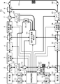
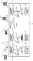
- FIG. 1 is a block diagram showing a configuration of a distributed optical fiber sensor according to the first embodiment of the present invention.
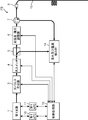
- FIG. 2 is a block diagram showing a schematic configuration of the distributed optical fiber sensor when the distributed optical fiber sensor shown in FIG. 1 is operated in the first mode.
- FIG. 3 is a block diagram showing a schematic configuration of the distributed optical fiber sensor when the distributed optical fiber sensor shown in FIG. 1 is operated in the second mode.
- FIG. 4 is a flowchart for explaining strain and temperature measurement operations by the distributed optical fiber sensor shown in FIG.
- FIG. 5 is a diagram for explaining the configuration and operation of the optical pulse generator shown in FIG.
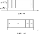
- FIG. 6 is a diagram for explaining the configuration of the pump light (sub-light pulse and main light pulse) and the matched filter.
- FIG. 1 is a block diagram showing a configuration of a distributed optical fiber sensor according to the first embodiment of the present invention.
- FIG. 2 is a block diagram showing a schematic configuration of the distributed optical fiber sensor when the distributed optical fiber sensor shown in FIG.
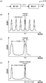
- FIG. 7 is a diagram illustrating an example of pulsed light emitted from the optical pulse generation unit illustrated in FIG. 1.
- FIG. 8 is a diagram showing an example of the Rayleigh frequency shift amount measured by the distributed optical fiber sensor shown in FIG.
- FIG. 9 is a diagram for explaining the relationship between the actual measurement position and the desired measurement position.
- FIG. 10 is a flowchart for explaining strain and temperature measurement operations by the distributed optical fiber sensor according to the second embodiment of the present invention.
- FIG. 11 is a diagram for explaining a method of deriving a correction amount.
- FIG. 12 is a diagram showing the peak frequency of the Brillouin spectrum at each position in the longitudinal direction of the detection optical fiber having a different type fiber connected in the middle.
- FIG. 13 is a schematic diagram for explaining the relationship between the reference Rayleigh spectrum and the measured Rayleigh spectrum.
- FIG. 14 is a diagram illustrating a reference Rayleigh spectrum and a measured Rayleigh spectrum.
- FIG. 15 is a diagram illustrating the relationship between the threshold and the cross-correlation coefficient.
- FIG. 16 is a diagram for explaining a method of determining a scanning range for obtaining the Rayleigh frequency shift amount from the relationship between the measured Rayleigh spectrum shift amount and the cross-correlation coefficient with respect to the reference Rayleigh spectrum.
- FIG. 17 is a diagram for explaining the effect of the correction based on the correction amount.
- FIG. 18 is a block diagram showing the configuration of the distributed optical fiber sensor when the distributed optical fiber sensor shown in FIG. 1 is configured as BOTDR.
- FIG. 19 is a diagram for explaining a narrow linewidth optical bandpass filter.
- FIG. 20 is a diagram for explaining a method for obtaining a Brillouin frequency shift by subtracting components from the whole.
- FIG. 21 is a diagram illustrating an experimental result of the distributed optical fiber sensor when the pump light having the configuration illustrated in FIG.
- FIG. 22 is a diagram for explaining another configuration of pump light (sub light pulse and main light pulse).
- FIG. 23 is a diagram illustrating an experimental result of the distributed optical fiber sensor when the pump light having the configuration illustrated in FIG. 22B is used.
- FIG. 24 is a diagram for explaining still another configuration of the pump light (sub light pulse and main light pulse) and a matched filter.
- FIG. 25 is a diagram for explaining the configuration and operation of an optical pulse generator for generating pump light having the configuration shown in FIG.
- FIG. 26 is a diagram illustrating waveforms of the sub light pulse and the main light pulse of another example.
- FIG. 27 is a diagram illustrating waveforms of the sub light pulse and the main light pulse of another example.
- FIG. 28 is a diagram illustrating waveforms of the sub light pulse and the main light pulse of another example.
- FIG. 29 is a diagram illustrating waveforms of the sub light pulse and the main light pulse of another example.
- FIG. 1 is a block diagram showing the configuration of the distributed optical fiber sensor in the first embodiment.
- the distributed optical fiber sensor FS shown in FIG. 1 includes a first light source 1, optical couplers 2, 5, 8, 21, 23, 30, an optical pulse generator 3, optical switches 4, 22, Polarization adjusting unit 6, optical circulators 7 and 12, optical connectors 9, 26, 27 and 28, a first automatic temperature control unit (hereinafter abbreviated as “first ATC”) 10, and a first automatic frequency control.
- first ATC first automatic temperature control unit
- first AFC first automatic frequency control unit
- second ATC Second automatic temperature controller
- second AFC second automatic frequency controller
- second AFC second light source 20
- An adjustment unit 24 and 1 ⁇ 2 optical switches 25, 29, and 31 are provided.
- the first and second light sources 1 and 20 are held substantially constant at a predetermined temperature preset by the first and second ATCs 10 and 18, respectively, and a predetermined frequency preset by the first and second AFCs 11 and 19, respectively. Is a light source device that generates and emits continuous light of a predetermined frequency by being held substantially constant.
- the output terminal (emission terminal) of the first light source 1 is optically connected to the input terminal (incident terminal) of the optical coupler 2.
- the output terminal (emission terminal) of the second light source 20 is optically connected to the input terminal (incident terminal) of the optical coupler 21.
- Each of the first and second light sources 1 and 20 is, for example, a light emitting element, a temperature detecting element (for example, a thermistor) that detects the temperature of the light emitting element, and a rear side of the light emitting element.
- a temperature detecting element for example, a thermistor
- One light branched by an optical coupler for example, a half mirror
- receives back light emitted from the light and splits it into two passes through a Fabry-Perot etalon filter that is a periodic filter.
- a first light receiving element for receiving light for receiving light
- a second light receiving element for receiving the other light branched by the optical coupler for receiving the other light branched by the optical coupler
- a temperature adjusting element for receiving the light emitting element, the temperature detecting element, the optical coupler, the first and second light receiving elements, a fabric And a substrate on which a Perot etalon filter and a temperature adjusting element are disposed.
- the light emitting element is an element that emits light of a predetermined frequency with a narrow line width and can change an oscillation wavelength (oscillation frequency) by changing an element temperature or a drive current.
- a multi-quantum well structure DFB laser and a tunable semiconductor laser (frequency tunable semiconductor laser) such as a tunable wavelength distribution Bragg reflection laser. Therefore, the first light source 1 also functions as a frequency variable light source.
- the temperature detection elements in the first and second light sources 1 and 20 output the detected temperatures to the first and second ATCs 10 and 18, respectively.
- the first and second light receiving elements in the first and second light sources 1 and 20 include photoelectric conversion elements such as photodiodes, for example, and output the respective light receiving outputs corresponding to the received light intensity to the first and second AFCs 11 and 19, respectively.
- the temperature adjustment element is a component that adjusts the temperature of the substrate by generating heat and absorbing heat, and includes, for example, a thermoelectric conversion element such as a Peltier element or a Seebeck element.
- the first and second ATCs 10 and 18 respectively control the temperature adjusting elements based on the detected temperatures of the temperature detecting elements in the first and second light sources 1 and 20 according to the control of the control processing unit 13, respectively.
- This circuit automatically keeps the temperature of each substrate at a predetermined temperature substantially constant. Thereby, the temperature of each light emitting element in the first and second light sources 1 and 20 is automatically kept substantially constant at a predetermined temperature. For this reason, when the frequency of the light emitted from the light emitting element has temperature dependency, the temperature dependency is suppressed.
- the first and second AFCs 11 and 19 respectively control the light emitting elements based on the light reception outputs of the first and second light receiving elements in the first and second light sources 1 and 20 according to the control of the control processing unit 13, respectively.
- the frequency of the light emitted from each light emitting element is automatically kept substantially constant at a predetermined frequency, or is swept within a predetermined frequency range.
- the optical coupler, the Fabry-Perot etalon filter, the first and second light receiving elements, and the first and second AFCs 11 and 19 in the first and second light sources 1 and 20 are the light emitting elements in the first and second light sources 1 and 20, respectively.
- So-called wavelength lockers that substantially fix the wavelength (frequency) of the emitted light are configured.
- the optical couplers 2, 5, 21, and 23 are optical components that distribute incident light incident from one input terminal into two lights and emit them to two output terminals, respectively.
- the optical coupler 8 emits incident light incident from one input terminal of the two input terminals from one output terminal, and transmits incident light incident from the other input terminal from the output terminal. It is an optical component to be emitted.
- the optical coupler 30 is an optical component that couples two incident lights incident from two input terminals and emits them from two output terminals.
- the optical couplers 2, 5, 21, 23, 8, and 30 are, for example, micro optical element type optical branch couplers such as half mirrors, fused fiber optical fiber type optical branch couplers, optical waveguide type optical branch couplers, and the like. Can be used.
- One output terminal of the optical coupler 2 is optically connected to the input terminal of the optical pulse generator 3, and the other output terminal is optically connected to the input terminal of the 1 ⁇ 2 optical switch 31.
- One output terminal of the optical coupler 5 is optically connected to the input terminal of the light intensity / polarization adjusting unit 6, and the other output terminal is optically connected to the input terminal of the strain and temperature detector 14.
- One output terminal of the optical coupler 21 is optically connected to the input terminal of the optical switch 22, and the other output terminal is optically connected to the other end of the reference optical fiber 17 via the optical connector 28.
- One output terminal of the optical coupler 23 is optically connected to the input terminal of the light intensity adjusting unit 24, and the other output terminal is optically connected to the input terminal of the strain and temperature detector 14.
- One input terminal of the optical coupler 8 is optically connected to the second terminal of the optical circulator 7, and the other input terminal is optically connected to the other output terminal of the 1 ⁇ 2 optical switch 25. Is optically connected to one end of the detection optical fiber 15 via the optical connector 9.
- One input terminal of the optical coupler 30 is optically connected to the other output terminal of the 1 ⁇ 2 optical switch 31, and the other input terminal is optically connected to one output terminal of the 1 ⁇ 2 optical switch 29.
- the two output terminals are optically connected to the input terminal of the strain and temperature detector 14.
- the light pulse generation unit 3 is a device that receives continuous light emitted from the first light source 1 and generates a main light pulse and a sub light pulse as pump light from the continuous light.
- the main light pulse is an optical pulse using a spread spectrum method. Examples of the spread spectrum method include a frequency chirp method that changes the frequency, a phase modulation method that modulates the phase, and a hybrid method that combines the frequency chirp method and the phase modulation method.
- Examples of the frequency chirp method include a method of changing the frequency monotonously, for example, linearly.
- Examples of the phase modulation method include a method of modulating the phase using a PN sequence.
- the PN sequence is a pseudo-random number sequence, and examples of the PN sequence include an M sequence (maximal-length sequences) and a Gold sequence.
- the M series can be generated by a circuit including a plurality of shift registers and a logic circuit that feeds back a logical combination of each state in each of the plurality of stages to the shift register.
- the Gold sequence is defined as M and Mj, where 0 is -1 and 1 is +1 corresponding to M sequence generated by n-th primitive polynomials F1 (x) and F2 (x), respectively.
- a Golay code sequence can be used as a phase modulation type pseudo-random number sequence.
- This Golay code sequence has an excellent characteristic that the side lobe of the autocorrelation function is strictly zero.
- the sub light pulse is an unmodulated unmodulated light pulse, the maximum light intensity of which is equal to or less than the light intensity of the main light pulse, and the pulse width is sufficiently longer than the lifetime of the acoustic phonon.
- the optical pulse generator 3 detects the optical fiber for detection before the sub optical pulse in time according to the control of the control processor 13.
- the sub light pulse and the main light pulse are generated so as not to be incident on the light beam 15.
- the sub light pulse and the main light pulse as the pump light generated by the light pulse generation unit 3 will be described later.
- the optical switches 4 and 22 are optical components that turn on / off light between the input terminal and the output terminal according to the control of the control processing unit 13. When on, light is transmitted, and when off, light is blocked.
- the optical switches 4 and 22 are light intensity modulators that modulate the light intensity of incident light, such as an MZ light modulator or a semiconductor electroabsorption optical modulator.
- the optical switches 4 and 22 include a driver circuit that is controlled by the control processing unit 13 and drives the light intensity modulator.
- This driver circuit is, for example, a DC power source that generates a DC voltage signal for turning off the light intensity modulator in a normal state, and a pulse generator that generates a voltage pulse for turning on the light intensity modulator that is normally turned off. And a timing generator for controlling the generation timing of the voltage pulse.
- the output terminal of the optical switch 4 is optically connected to the input terminal of the optical coupler 5.
- the output terminal of the optical switch 22 is optically connected to the input terminal of the optical coupler 23.
- the light intensity / polarization adjusting unit 6 is a component that is controlled by the control processing unit 13 to adjust the light intensity of the incident light and emit the light by changing the polarization plane of the incident light at random.
- the output terminal of the light intensity / polarization adjustment unit 6 is optically connected to the first terminal of the optical circulator 7.
- the light intensity / polarization adjustment unit 6 attenuates the light intensity of the incident light and emits it, and changes the amount of attenuation, and changes the polarization plane of the incident light at random.
- a polarization controller that can be configured.
- the light intensity / polarization adjusting unit 6 is commonly used for measurement of stimulated Brillouin scattered light and Rayleigh backscattered light, and randomly changes the polarization plane of the light.
- Optical circulators 7 and 12 are irreversible optical components in which incident light and outgoing light have a cyclic relationship with their terminal numbers. That is, the light incident on the first terminal is emitted from the second terminal and is not emitted from the third terminal, and the light incident on the second terminal is emitted from the third terminal and the first terminal. The light which is not emitted from the first terminal but is incident on the third terminal is emitted from the first terminal and is not emitted from the second terminal.
- the first terminal of the optical circulator 7 is optically connected to the output terminal of the light intensity / polarization adjustment unit 6, the second terminal is optically connected to one input terminal of the optical coupler 8, and the third terminal is It is optically connected to the input terminal of the 1 ⁇ 2 optical switch 29.
- the first terminal of the optical circulator 12 is optically connected to one output terminal of the 1 ⁇ 2 optical switch 31, and the second terminal is optically connected to one end of the reference optical fiber 17 via the optical connector 27.
- the third terminal is optically connected to the input terminal of the strain and temperature detector 14.
- Optical connectors 9, 26, 27, and 28 are optical components that optically connect optical fibers or optical components and optical fibers.
- the light intensity adjusting unit 24 is a component that is controlled by the control processing unit 13 and adjusts the light intensity of incident light and emits the light.
- the output terminal of the light intensity adjusting unit 24 is optically connected to the input terminal of the optical switch 25.
- the light intensity adjusting unit 24 includes, for example, an optical variable attenuator that attenuates and emits light intensity of incident light, and an optical isolator that transmits light only in one direction from the input terminal to the output terminal.
- the incident light that has entered the light intensity adjusting unit 24 is emitted through an optical isolator after the light intensity is adjusted to a predetermined light intensity by an optical variable attenuator.
- This optical isolator plays a role of preventing the propagation of reflected light generated at the connection portion of each optical component in the distributed optical fiber sensor FS and the propagation of the sub light pulse and the main light pulse to the second light source 20.
- the 1 ⁇ 2 optical switches 25, 29, 31 are 1-input 2-output optical switches that emit light from one of the two output terminals by switching the optical path,
- a mechanical optical switch or an optical waveguide switch is used.
- One output terminal of the 1 ⁇ 2 optical switch 25 is optically connected to the other input terminal of the optical coupler 8, and the other output terminal is optically connected to the other end of the detection optical fiber 15 via the optical connector 26. Connected.
- BOTDA Brillouin spectrum time domain analysis
- the 1 ⁇ 2 optical switch 25 When the 1 ⁇ 2 optical switch 25 is switched so as to be incident on the other end of the optical fiber 15 and operated in the second mode of Brillouin spectrum time domain analysis (BOTDA) (one-end measurement), from the input terminal
- BOTDA Brillouin spectrum time domain analysis
- One output terminal of the 1 ⁇ 2 optical switch 29 is optically connected to the other input terminal of the optical coupler 30, and the other output terminal is optically connected to the strain and temperature detector 14.
- BOTDA Brillouin spectrum time domain analysis
- BOTDA second mode of Brillouin spectrum time domain analysis
- the 1 ⁇ 2 optical switch 29 is switched so that the incident light enters the strain and temperature detector 14 and operates as a coherent optical pulse tester (COTDR) using the Rayleigh scattering phenomenon
- COTDR coherent optical pulse tester
- One output terminal of the 1 ⁇ 2 optical switch 31 is optically connected to the first terminal of the optical circulator 12, and the other output terminal is optically connected to one input terminal of the optical coupler 30.
- BOTDA Brillouin spectrum time domain analysis
- BOTDA second mode of Brillouin spectrum time domain analysis
- the 1 ⁇ 2 optical switch 31 is switched so that the incident light enters the optical circulator 12 and operates as a coherent optical pulse tester (COTDR) using the Rayleigh scattering phenomenon, the light is incident from the input terminal.
- COTDR coherent optical pulse tester
- the 1 ⁇ 2 optical switch 31 is switched so that light is incident on one input terminal of the optical coupler 30.
- the detection optical fiber 15 is an optical fiber for a sensor that detects strain and temperature.
- BOTDA a sub-light pulse, a main light pulse, and continuous light are incident, and light subjected to the action of stimulated Brillouin scattering is generated.
- pulsed light is incident and light subjected to the effect of the Rayleigh scattering phenomenon is emitted.
- the detection optical fiber 15 is an adhesive or a fixing member. It is fixed to the measurement object by such as.
- the reference optical fiber 17 is an optical fiber used for adjusting the frequency of each light emitted from the first and second light sources 1 and 20, and the first and second light causing the stimulated Brillouin scattering phenomenon.
- the optical fiber has a known relationship between the frequency difference in the light and the light intensity of light related to the stimulated Brillouin scattering phenomenon. Further, the reference optical fiber 17 may be used for adjustment of light used for measurement of Rayleigh backscattered light.
- the temperature detector 16 is a circuit that detects the temperature of the reference optical fiber 17 and outputs the detected temperature to the control processor 13.
- the strain and temperature detector 14 includes a light receiving element, an optical switch, an amplifier circuit, an analog / digital converter, a signal processing circuit, a spectrum analyzer, a computer, and the like.
- the strain and temperature detector 14 controls each unit of the distributed optical fiber sensor FS by inputting and outputting signals to and from the control processing unit 13.
- the strain and temperature detector 14 obtains the light intensity of the light related to the stimulated Brillouin scattering phenomenon, which is incident on the input terminal via the optical connector 27 and the optical circulator 12 and is emitted from the reference optical fiber 17. The intensity is output to the control processing unit 13.
- the strain and temperature detector 14 controls each part of the distributed optical fiber sensor FS by inputting and outputting signals to and from the control processing unit 13, and the 1 ⁇ 2 optical switch 29 is connected to the optical circulator 7 and the strain and temperature.
- the detector 14 is connected, and light related to the stimulated Brillouin scattering phenomenon is incident on a light receiving element having one input terminal for the stimulated Brillouin scattered light in the strain and temperature detector 14.
- the strain and temperature detector 14 is connected to a light receiving element for stimulated Brillouin scattered light by an internal switch and an amplifier circuit, and detects light related to the stimulated Brillouin scattering phenomenon received at a predetermined sampling interval.
- the Brillouin spectrum of each region portion of the detection optical fiber 15 in the longitudinal direction of the optical fiber 15 is obtained, and the Brillouin frequency shift amount of each region portion is obtained based on the obtained Brillouin spectrum of each region portion.
- the strain and temperature detector 14 controls each part of the distributed optical fiber sensor FS by inputting / outputting signals to / from the control processing unit 13, and the 1 ⁇ 2 optical switch 29 includes the optical circulator 7 and the optical coupler 30.
- the strain and temperature detector 14 is connected to a light receiving element for Rayleigh backscattered light and an amplifier circuit by an internal switch, and detects light related to the Rayleigh backscatter phenomenon received at a predetermined sampling interval.
- the Rayleigh spectrum of each region portion of the detection optical fiber 15 in the longitudinal direction of the optical fiber 15 is obtained, and the Rayleigh frequency shift amount of each region portion is obtained based on the obtained Rayleigh spectrum of each region portion.
- the strain and temperature detector 14 detects the strain distribution and the temperature distribution of the detection optical fiber 15 simultaneously and independently from the Brillouin frequency shift amount and the Rayleigh frequency shift amount obtained as described above.
- Each incident light incident from each input terminal of the strain and temperature detector 14 is converted into an electrical signal corresponding to the amount of received light by a light receiving element that performs photoelectric conversion.
- Incident light incident as light related to the stimulated Brillouin scattering phenomenon is directly detected by being converted into an electric signal by a light receiving element, filtered by a matched filter, converted to a digital electric signal by an analog / digital converter, Used to determine Brillouin spectrum.
- Incident light incident as light related to the Rayleigh backscattering phenomenon is directly detected by being converted into an electric signal by a light receiving circuit, filtered by a matched filter, converted to a digital electric signal by an analog / digital converter, Used to determine the Rayleigh spectrum. Further, if necessary, the electric signal is amplified by the amplifier circuit before being digitally converted.
- the control processing unit 13 includes, for example, a microprocessor, a working memory, and a memory that stores data necessary for measuring the strain and temperature distribution of the detection optical fiber 15 with high spatial resolution.
- the control processing unit 13 inputs and outputs a signal to and from the strain and temperature detector 14 to thereby distribute the strain and temperature distribution of the detection optical fiber 15 in the longitudinal direction of the detection optical fiber 15 with high spatial resolution and further.
- First and second light sources 1 and 20, first and second ATCs 10 and 18, first and second AFCs 11 and 19, optical pulse generator 3, optical switches 4 and 22, and light intensity / polarization adjustment so as to measure up to a distance 6 is an electronic circuit that controls the unit 6, 1 ⁇ 2 optical switches 25, 29, and 31, and the light intensity adjusting unit 24.
- the control processing unit 13 includes a storage unit in which the relationship between the frequency difference between the first and second lights causing the stimulated Brillouin scattering phenomenon and the light intensity of the light related to the stimulated Brillouin scattering phenomenon in the reference optical fiber 17 is stored. First and second in the first and second light sources 1 and 20 based on the light intensity of the light related to the stimulated Brillouin scattering phenomenon obtained by the strain and temperature detector 14 and the known relationship in the reference optical fiber 17. A frequency setting unit that controls the first AFC 11 and / or the second AFC 19 is functionally provided so that the frequency difference of each light emitted from the light emitting element becomes a predetermined frequency difference set in advance. In addition, the control processing unit 13 functionally includes a frequency setting unit that controls the first AFC 11 so as to emit light that causes the Rayleigh backscattering phenomenon in the reference optical fiber 17.
- Patent Document 1 can be referred to.
- Spread spectrum method or pulse compression method is used to extend the measurable distance in the so-called radar field. This is because the spectrum of the pulse is diffused by using frequency modulation, phase modulation, etc. inside the pulse radiated to the space to detect the target, and demodulation called pulse compression is applied to the reflected wave reflected by the target. By doing so, the distance to the target is detected. Thereby, the energy of the pulse can be increased, and the measurable distance can be extended.
- Spread spectrum is generally deliberately increasing the bandwidth that is originally required to transmit a signal.
- BOTDA Brillouin gain spectrum
- the pump light A p (0, t) is an optical pulse having a shape whose complex envelope is expressed by the equation (1).
- P p is the power of the pump light
- f (t) is a function representing the amplitude of the pump light at time t, and is normalized so that the maximum of its absolute value is 1. .
- Equation (3) the Brillouin gain spectrum V (t, ⁇ ) is a two-dimensional convolution (convolution), and is represented by equation (4).
- Equation (4) The first term on the right side of Equation (4) is a time-varying Lorentz spectrum.
- the superscript * represents a complex conjugate
- ⁇ is a gain coefficient
- ⁇ B (z) is a Brillouin frequency shift at the position z.
- G ( ⁇ ) is a Lorentz spectrum
- vg is a group velocity of pump light.
- the operator * represents convolution
- the superscripts t and ⁇ represent two-dimensional convolution with respect to these variables. Note that the multiplication operator • is not shown.
- the pump light is composed of the main light pulse f 1 (t) and the sub light pulse f 2 (t).
- the amplitude f (t) of the pump light is expressed by Equation (5).
- This sub light pulse functions to excite acoustic phonons for the main light pulse.
- the pulse width D sub of the sub light pulse is made sufficiently longer than at least the lifetime of the acoustic phonon.
- the lifetime of acoustic phonons is usually about 5 ns.
- This main light pulse functions to pass the energy scattered by the acoustic phonon to the probe light.
- the main light pulse is divided into a plurality of cells with a predetermined time width in the time direction, and is broadened by using a spread spectrum system. Broadband is compared to the spectral linewidth of acoustic phonons (approximately 30-40 MHz).
- the time width of this cell determines the spatial resolution of BOTDA, and this reciprocal is the width of the spectrum. For example, when the cell width (cell time width) is 0.1 ns, the spatial resolution is 1 cm and the spectrum width is 10 GHz.
- the pulse width D of the main light pulse determines the amount of energy given to the pump light in order to extend the measurable distance.
- the pulse width D of the main optical pulse can be set independently of the spatial resolution of BOTDA. Therefore, the pulse width D of the main light pulse can be appropriately determined according to a desired measurable distance. For this reason, it becomes possible to extend measurable distance conventionally.
- the point spread function ⁇ (t, ⁇ ) is expressed by the equation (8). Since the pump light is composed of the main light pulse and the sub light pulse, this point spread function ⁇ (t, ⁇ ) Is represented by Equation (9) and Equation (10).
- the matched filter for example, inverts the signal used for spread spectrum (the code in the case of using a code sequence for spread spectrum) with respect to time and takes the convolution with the input of the matched filter.
- the main light pulse uses a spread spectrum system, and the sub light pulse is unmodulated and its pulse width is sufficiently long. Therefore, the components ⁇ 1,2 (t, ⁇ ) can be approximated as in equation (11), and is the preferred type.
- C p is an amplitude ratio between the main light pulse and the sub light pulse.
- V 1,1 (t, ⁇ ) and V 2,1 (t, ⁇ ) in the Brillouin gain spectrum V (t, ⁇ ) are spectrally spread by a pseudorandom number of the main light pulse. In some cases, the spectrum is flat.
- the other components V 2,2 (t, ⁇ ) are suppressed by the matched filter at the time of demodulation.
- V 1,1 (t, ⁇ ) and V 2,2 (t, ⁇ ) in the Brillouin gain spectrum V (t, ⁇ ) are composed of only the main light pulse or the sub light pulse. And can be extracted by measuring the Brillouin gain spectrum.
- the optical pulse incident on the detection optical fiber is composed of two components of the main optical pulse using the spread spectrum method and the unmodulated sub optical pulse, Since the spatial resolution and the measurable distance can be set independently, the measurable distance can be extended and further measured while the strain and temperature can be measured with high spatial resolution.
- FIG. 2 is a block diagram showing a schematic configuration of the distributed optical fiber sensor when the distributed optical fiber sensor shown in FIG. 1 is operated in the first mode.
- the distributed optical fiber sensor FS uses the sub light pulse and the main light pulse generated by the light pulse light source LS p as pump light, and detects for detecting strain and temperature.
- the incident light is incident from one end of the optical fiber 15 and the continuous light generated by the continuous light source LS CW is incident as the probe light from the other end of the detecting optical fiber 15.
- the distributed optical fiber sensor FS receives light related to the stimulated Brillouin scattering phenomenon generated in the detection optical fiber 15 by the strain and temperature detector 14, and the Brillouin gain spectrum time domain analysis (The Brillouin frequency shift amount is measured by performing B Gain -OTDA) or Brillouin loss spectrum time domain analysis (B Loss -OTDA).
- the laser light emitted from the laser light source LD is phase-modulated by the pseudo random number from the pseudo random number generator RG in the optical signal generator OSG, so that the main optical pulse using the spread spectrum system is generated. Generated.
- the pseudorandom number generated by the pseudorandom number generator RG is notified to the strain and temperature detector 14 for demodulation.
- the strain and temperature detector 14 the light related to the stimulated Brillouin scattering phenomenon emitted from the detection optical fiber 15 is filtered by the matched filter MF corresponding to the pseudo random number from the pseudo random number generator RG, and the signal processing unit By performing BOTDA signal processing at the SP, the Brillouin frequency shift amount is measured.
- Brillouin gain spectrum time domain analysis or Brillouin loss spectrum time domain analysis is abbreviated as Brillouin spectrum time domain analysis as appropriate.
- light related to the stimulated Brillouin scattering phenomenon is light that has undergone Brillouin amplification or attenuation.
- the distributed optical fiber sensor FS shown in FIG. 1 functions as a BOTDA when measuring the Brillouin frequency shift amount, and operates as the second mode (one-end measurement) by switching the optical switches 25, 29, and 31.
- FIG. 3 is a block diagram showing a schematic configuration of the distributed optical fiber sensor when the distributed optical fiber sensor shown in FIG. 1 is operated in the second mode.
- the distributed optical fiber sensor FS uses the sub light pulse and the main light pulse generated by the light pulse light source LS p as pump light and is generated by the continuous light source LS CW .
- the continuous light thus made is incident from one end of the detection optical fiber 15 as probe light.
- a spread spectrum method is used for the main light pulse.
- the distributed optical fiber sensor FS receives light related to the stimulated Brillouin scattering phenomenon generated in the detection optical fiber 15 by the strain and temperature detector 14, and the Brillouin gain spectrum time domain analysis (The Brillouin frequency shift amount is measured by performing B Gain -OTDA) or Brillouin loss spectrum time domain analysis (B Loss -OTDA).
- each frequency of each continuous light emitted from the first and second light sources 1 and 20 is adjusted (calibrated) using the reference optical fiber 17.
- control processing unit 13 controls the first ATC 10 and the first AFC 11, and the second ATC 18 and the second AFC 19, respectively, so that the first and second light sources 1 and 20 emit respective continuous lights at respective predetermined frequencies.
- the light is emitted and the continuous light is incident on the reference optical fiber 17 so as to face each other.
- the continuous light from the first light source 1 and the continuous light from the second light source 20 cause a stimulated Brillouin scattering phenomenon in the reference optical fiber 17, and the light related to the stimulated Brillouin scattering phenomenon is transmitted from the reference optical fiber 17.
- the light enters the strain and temperature detector 14 via the circulator 12.
- the strain and temperature detector 14 receives the light related to the stimulated Brillouin scattering phenomenon, detects the light intensity of the received light related to the stimulated Brillouin scattering phenomenon, and notifies the control processing unit 13 of the detected light intensity. .
- the control processing unit 13 the relationship between the frequency difference between the first and second lights causing the stimulated Brillouin scattering phenomenon and the light intensity of the light related to the stimulated Brillouin scattering phenomenon in the reference optical fiber 17 is stored in advance in the storage unit. Has been.
- the control processing unit 13 responds to the predetermined frequency difference fa to be set for each light emitted by the first and second light emitting elements in the first and second light sources 1 and 20 by the frequency setting unit.
- the reference light intensity Pa to be obtained is obtained from the above relationship, and the first AFC 11 and the second AFC 19 are controlled so that the measured light intensity Pd detected by the strain and temperature detector 14 coincides with the reference light intensity Pa.
- the frequency difference between the lights emitted from the first and second light emitting elements in the first and second light sources 1 and 20 is adjusted to a predetermined frequency difference fa to be set.
- the light intensity Pd is given by a voltage value photoelectrically converted by the light receiving element
- the reference light intensity Pa is a voltage value corresponding to the reference light intensity Pa.
- the relationship between the frequency difference between the first and second lights causing the stimulated Brillouin scattering phenomenon and the light intensity of the light related to the stimulated Brillouin scattering phenomenon generally has temperature dependence. Yes.
- the control processing unit 13 detects the temperature of the reference optical fiber 17 by the temperature detection unit 16 and corrects the relationship in the reference optical fiber 17 according to the detected temperature. ing. For this reason, adjustment can be executed with higher accuracy.
- each frequency of each continuous light emitted from the first and second light sources 1 and 20 is adjusted. Such adjustment may be performed every time the frequency is changed for the sweep when obtaining the Brillouin spectrum from the viewpoint of further improving the measurement accuracy, or from the viewpoint of shortening the measurement time.
- the strain and temperature may be executed every measurement, every time a predetermined period elapses, or even when the distributed optical fiber sensor FS is activated.
- FIG. 4 is a flowchart for explaining strain and temperature measurement operations by the distributed optical fiber sensor FS shown in FIG.
- step S1 the strain and temperature detector 14, the Brillouin frequency shift amount ⁇ b are estimated, the frequency sweep range for measuring the Brillouin frequency shift amount ⁇ b is determined, and the first and second sweep ranges are determined.
- the control processing unit 13 is instructed to emit each continuous light from the light sources 1 and 20.
- the estimation of the Brillouin frequency shift amount ⁇ b here is performed based on, for example, the predicted maximum temperature change amount and maximum strain change amount. Since the frequency sweep range for measuring the Brillouin frequency shift amount is narrow, the frequency sweep range can be easily estimated.
- step S2 the strain and temperature detector 14 measures the Brillouin frequency shift amount ⁇ b.
- the Brillouin frequency shift amount ⁇ b is obtained by the following processing.
- control processing unit 13 controls the first ATC 10 and the first AFC 11 and the second ATC 18 and the second AFC 19 to cause the first and second light sources 1 and 20 to emit respective continuous lights at respective predetermined frequencies.
- the continuous light emitted from the first light source 1 is incident on the optical pulse generator 3 via the optical coupler 2
- the continuous light emitted from the second light source 20 is incident on the optical switch 22 via the optical coupler 21. Is done.
- control processing unit 13 controls the optical pulse generation unit 3 to generate predetermined pump light (sub optical pulse and main optical pulse). More specifically, the control processing unit 13 generates pump light by operating the optical pulse generation unit 3 as follows, for example.
- FIG. 5 is a diagram for explaining the configuration and operation of the optical pulse generator 3 shown in FIG. 6A and 6B are diagrams for explaining the configuration of the pump light (sub-light pulse and main light pulse) and the matched filter.
- FIG. 6A shows the configuration of the pump light
- FIG. It is a figure which shows a matched filter.
- the optical pulse generation unit 3 includes an LN intensity modulator 101 that modulates the light intensity of incident light, and a DC power source that constitutes a first drive circuit for driving the LN intensity modulator 101. 102, a multiplier 103 and a timing pulse generator 104, an LN phase modulator 111 that modulates the phase of incident light, a DC power source 112 that constitutes a second drive circuit for driving the LN phase modulator 111, and a multiplier 113, a pseudo random number generator 114, an erbium-doped optical fiber amplifier (EDFA) 121, an LN intensity modulator 131 for modulating the light intensity of incident light, and a third drive circuit for driving the LN intensity modulator 131.
- a DC power supply 132, a multiplier 133, and a timing pulse generator 134 are included.
- the LN phase modulator 111 is formed by, for example, forming an optical waveguide, a signal electrode, and a ground electrode on a lithium niobate substrate having an electro-optic effect, and by applying a predetermined signal between the electrodes.
- the apparatus modulates the phase of incident light by using the phase change accompanying the refractive index change caused by the electro-optic effect as it is.
- the LN intensity modulators 101 and 131 are devices that modulate the light intensity of incident light by, for example, configuring a Mach-Zehnder interferometer and changing a phase change accompanying a refractive index change due to an electro-optic effect to an intensity change.
- the LN intensity modulators 101 and 131 and the LN phase modulator 111 have other electro-optical effects such as lithium tantalate, lithium niobate / lithium tantalate, and the like instead of the lithium niobate substrate.
- a substrate may be used.
- the DC power supply 102 is a power supply circuit that generates a DC voltage to be applied to the signal electrode of the LN intensity modulator 101 in order to modulate the intensity
- the timing pulse generator 104 includes the LN intensity modulator 101.
- a pulse generation circuit that generates an operation timing pulse for operation, and a multiplier 103 multiplies the DC voltage input from the DC power supply 102 by the operation timing pulse input from the timing pulse generator 104, This is a circuit that outputs a DC voltage corresponding to the operation timing pulse to the LN intensity modulator 101.
- the DC power supply 112 is a power supply circuit that generates a DC voltage to be applied to the signal electrode of the LN phase modulator 111 for phase modulation, and the pseudo-random number generator 114 converts the incident light into a spread spectrum system.
- the pseudo random number generation circuit generates a pseudo random number at an operation timing in order to operate the LN phase modulator 111 so as to modulate at a DC voltage.
- the multiplier 113 is a DC voltage input from the DC power source 112 and a pseudo random number generator 114. Is a circuit that outputs a DC voltage corresponding to the pseudo-random number to the phase modulator 111.
- the EDFA 121 is an optical component that includes an optical fiber doped with erbium, and amplifies and emits incident light.
- the EDFA 121 amplifies incident light at a predetermined amplification factor set in advance so as to obtain a light intensity suitable for detection of strain and temperature in the detection optical fiber 15.
- a loss occurs during propagation from the first light source 1 to the detection optical fiber 15, this loss is also compensated, and measurement in a predetermined measurement range becomes possible.
- the DC power supply 132 is a power supply circuit that generates a DC voltage to be applied to the signal electrode of the LN intensity modulator 131 in order to intensity-modulate the LN intensity modulator 131 so as to perform on / off control.
- the timing pulse generator 134 is a pulse generation circuit that generates an operation timing pulse in order to operate the LN intensity modulator 131.
- the multiplier 133 receives the DC voltage input from the DC power supply 132 and the timing pulse generator 134. This circuit multiplies the input operation timing pulse and outputs a DC voltage corresponding to the operation timing pulse to the LN intensity modulator 131.
- pump light having a configuration shown in FIG. 6A can be generated.
- the pump light shown in FIG. 6A is unmodulated with the main light pulse encoded by the spread spectrum method, and precedes in time without overlapping (without overlapping) the main light pulse. And sub-light pulses.
- the main optical pulse is divided into a plurality of cells with a predetermined time width (cell width), and in the present embodiment, each cell is modulated (encoded) with an M-sequence binary code.
- the cell width is set according to the desired spatial resolution
- the pulse width of the main light pulse is set according to the desired measurement distance.
- the sub light pulse has a pulse width that can completely raise the acoustic phonon, and in the example shown in FIG. 6A, the light intensity is the same as the light intensity of the main light pulse.
- the sub light pulse and the main light pulse are continuous in time, but may be separated in time.
- the time interval between the sub light pulse and the main light pulse is preferably within about 5 ns.
- the continuous light L1 emitted from the first light source 1 passes through the optical coupler 2 and the LN intensity of the optical pulse generator 3. The light enters the modulator 101.
- the pulse width (D sub + D) operation timing pulse is a timing pulse generator which corresponds to the pulse width D of the pulse width D sub and main light pulse of the sub light pulse
- the voltage is output from 104 to the multiplier 103, multiplied by the DC voltage input from the DC power supply 102, and a DC voltage having a pulse width (D sub + D) is applied to the signal electrode of the LN intensity modulator 101.
- the LN intensity modulator 101 is turned on for a time width (D sub + D) corresponding to the pulse width (D sub + D) according to the operation timing pulse, and the continuous light L1 is turned on.
- an optical pulse L2 having a pulse width (D sub + D) is emitted.
- the pseudo random number is multiplied from the pseudo random number generator 114 by the time timing of the cell width during the time width D corresponding to the pulse width D of the main optical pulse at the generation timing of the main optical pulse.
- the DC voltage is sequentially output to 113, multiplied by the DC voltage input from the DC power supply 112, and the DC voltage modulated with the M-sequence binary code from the generation timing of the main optical pulse is modulated with the time width D.
- the signals are sequentially applied to the signal electrodes of the phase modulator 111.
- the DC voltage modulated by the M-sequence binary code is emitted from the LN phase modulator 111 when the DC voltage corresponding to the case where the M-sequence binary code is “+” is supplied to the LN phase modulator 111.
- the phase of light and the phase of light emitted from the LN phase modulator 111 are 180 degrees different from each other when a DC voltage corresponding to the case where the M-sequence binary code is “ ⁇ ” is supplied to the LN phase modulator 111. It is a correct voltage value.
- the optical pulse L2 is an optical pulse composed of an unmodulated portion (corresponding to the sub optical pulse) and a portion modulated by the M-sequence binary code (corresponding to the main optical pulse) by the LN phase modulator 111. Injected as L3.
- the light pulse L3 is amplified until it reaches a predetermined light intensity, and is emitted as the light pulse L4.
- operation timing pulses having a pulse width (D sub + D) corresponding to the pulse width D sub of the sub optical pulse and the pulse width D of the main optical pulse are timing according to the generation timing of the pump light.
- the pulse generator 134 outputs to the multiplier 133 and is multiplied by the DC voltage input from the DC power supply 132, and a DC voltage having a pulse width (D sub + D) is applied to the signal electrode of the LN intensity modulator 131.
- the optical pulse L4 is a sub-optical pulse that has an LN intensity modulator 131 to remove noise such as spontaneous emission light (ASE) associated with the optical pulse L4 by the EDFA 121, and has a pulse width D sub and is not modulated.
- pump light L5 having the pulse width D and the main light pulse encoded by the spread spectrum method.
- control processing unit 13 turns on the optical switch 4 and the optical switch 22 according to the generation timing of the pump light (sub optical pulse, main optical pulse, and optical pulse L4) in the optical pulse generation unit 3.
- the control processing unit 13 notifies the distortion and temperature detector 14 of the generation timing of the pump light (sub light pulse and main light pulse).
- the pump light (sub light pulse and main light pulse) is incident on the optical coupler 5 and branched into two.
- One of the branched pump lights is incident on the light intensity / polarization adjustment unit 6, the light intensity is adjusted by the light intensity / polarization adjustment unit 6, and the polarization direction is adjusted randomly (randomly). 7, and enters one end of the detection optical fiber 15 via the optical coupler 8 and the optical connector 9.
- the other sub light pulse and the main light pulse branched by the optical coupler 5 enter the strain and temperature detector 14.
- the strain and temperature detector 14 measures the spectrum of the pump light (sub light pulse and main light pulse) and notifies the control processing unit 13 of the frequency and light intensity of the pump light. Upon receiving this notification, the control processing unit 13 controls the first ATC 10, the first AFC 11, and the light intensity / polarization adjustment unit 6 as necessary so that an optimum measurement result can be obtained.
- the optical switch 22 when the optical switch 22 is turned on, the continuous light (probe light) is incident on the optical coupler 23 and branched into two. One of the branched probe lights (continuous light) is incident on the light intensity adjusting unit 24, the light intensity of which is adjusted by the light intensity adjusting unit 24, and incident on the 1 ⁇ 2 optical switch 25.
- the 1 ⁇ 2 optical switch 25 is configured such that light incident from the input terminal is connected to the other end of the detection optical fiber 15 via the optical connector 26.
- the probe light (continuous light) is incident on the other end of the detection optical fiber 15 via the optical connector 26.
- the 1 ⁇ 2 optical switch 25 detects light incident from the input terminal via the optical coupler 8 and the optical connector 9.
- the probe light continuously light
- the probe light is switched to be incident on one end of the optical fiber 15, and is incident on one end of the detection optical fiber 15 via the optical coupler 8 and the optical connector 9.
- the other probe light continuously light branched by the optical coupler 23 enters the strain and temperature detector 14.
- the strain and temperature detector 14 measures the spectrum of the probe light (continuous light) and notifies the control processor 13 of the frequency and light intensity of the probe light. Upon receiving this notification, the control processing unit 13 controls the second ATC 18, the second AFC 19, and the light intensity adjustment unit 24 as necessary so that an optimum measurement result can be obtained.
- pump light (sub-light pulse and main light pulse) incident on one end of the detection optical fiber 15 is incident from the other end of the detection optical fiber 15 and is detected.
- the detection optical fiber 15 propagates from one end to the other end while causing a probe light (continuous light) propagating 15 and a stimulated Brillouin scattering phenomenon.
- the pump light (sub light pulse and main light pulse) incident on one end of the detection optical fiber 15 is incident from one end of the detection optical fiber 15 and is detected.
- the probe light (continuous light) that is reflected at the other end of the light 15 and propagates through the detection optical fiber 15 is propagated from one end to the other end of the detection optical fiber 15 while causing a stimulated Brillouin scattering phenomenon.
- On / off timings of the optical switch 4 and the optical switch 22 are adjusted by the control processing unit 13 based on the interaction between the pump light and the probe light.
- the strain and temperature detector 14 In the 1 ⁇ 2 optical switch 29, when Brillouin spectrum time domain analysis (BOTDA) is performed in the first mode or the second mode, light incident from the input terminal is incident on the strain and temperature detector 14. It is switched as follows. Therefore, the light related to the stimulated Brillouin scattering phenomenon is emitted from one end of the detection optical fiber 15, and the strain and temperature detector 14 is passed through the optical connector 9, the optical coupler 8, the optical circulator 7, and the 1 ⁇ 2 optical switch 29. Is incident on.
- BOTDA Brillouin spectrum time domain analysis
- the light related to the stimulated Brillouin scattering phenomenon is extracted by direct detection as described above, converted into an electric signal by the light receiving element, and filtered by the matched filter.
- this matched filter is a phase modulation pattern (P 1 P 2 P 3 ).
- P n ⁇ 1 P n is a filter of an antiphase modulation pattern (P n P n ⁇ 1 ... P 3 P 2 P 1 ) obtained by temporally inverting P n ⁇ 1 P n ).
- the matched filter converts the phase modulation pattern temporally.
- the reverse pattern of “ ⁇ +... + ⁇ ++ ⁇ +” is inverted.
- the degree of interaction between pump light (sub light pulse and main light pulse) and probe light (continuous light) related to the stimulated Brillouin scattering phenomenon depends on the relative relationship between the polarization planes of these lights.
- the polarization plane of the pump light randomly changes in the light intensity / polarization adjustment unit 6 for each measurement, the measurement is performed a plurality of times and the average value is adopted. Thus, this dependency can be substantially eliminated. For this reason, the light intensity distribution of the light related to the stimulated Brillouin scattering phenomenon can be obtained with high accuracy.
- the distribution of the light intensity of the light related to the stimulated Brillouin scattering phenomenon in the longitudinal direction of the detection optical fiber 15 is, for example, the frequency of the probe light (continuous light) emitted from the second light source 20.
- the frequency of the probe light (continuous light) emitted from the second light source 20 By sweeping in a predetermined frequency range at predetermined frequency intervals by control, measurement is performed with high accuracy and high spatial resolution at each frequency. As a result, a Brillouin spectrum in each region in the longitudinal direction of the detection optical fiber 15 can be obtained with high accuracy and high spatial resolution.
- the strain and temperature detector 14 detects the frequency corresponding to the peak of the Brillouin spectrum in each region in the longitudinal direction of the detection optical fiber 15 in a state in which no strain is generated and the state in which the strain is generated.
- the length of the detection optical fiber 15 is determined by obtaining the difference from the frequency corresponding to the peak of the Brillouin spectrum in the region corresponding to each region where no distortion occurs.
- the Brillouin frequency shift amount in each part in the scale direction is obtained with high accuracy and high spatial resolution.
- step S3 the strain and temperature detector 14 estimates the Rayleigh frequency shift amount ⁇ r from the Brillouin frequency shift amount ⁇ b obtained by the above processing, and in step S4, estimates the Rayleigh frequency shift amount ⁇ r.
- the sweep range of the frequency of the pulsed light for measuring the Rayleigh backscattered light is determined from the Rayleigh frequency shift amount ⁇ r.
- the Brillouin frequency shift amount ⁇ b and the Rayleigh frequency shift amount ⁇ r are expressed by the following equations, where ⁇ is the strain change amount and ⁇ T is the temperature change amount.
- ⁇ is the strain change amount
- ⁇ T is the temperature change amount.
- R11 ⁇ -0.15GHz / ⁇ it is R12 ⁇ -1.25GHz / °C.
- ⁇ b B11 ⁇ ⁇ + B12 ⁇ ⁇ T (13)
- ⁇ r R11 ⁇ ⁇ + R12 ⁇ ⁇ T (14)
- the sensitivity of the Rayleigh frequency shift amount ⁇ r is very high compared to the Brillouin frequency shift amount ⁇ b. This is very advantageous for improving the measurement accuracy, but determines the frequency sweep range for measuring the Rayleigh frequency shift amount ⁇ r as well as the frequency sweep range for measuring the Brillouin frequency shift amount ⁇ b. In this case, the frequency sweep range for measuring the Rayleigh frequency shift amount ⁇ r becomes very wide, and the measurement takes a long time.
- the Rayleigh frequency shift amount ⁇ r is estimated from the already measured Brillouin frequency shift amount ⁇ b.
- ⁇ T 300 ° C.
- the two frequencies obtained as described above may be used as they are, or a predetermined measurement margin amount may be added as appropriate, or the sweep range may be set by a predetermined amount in order to shorten the measurement time.
- Various changes such as narrowing are possible.
- the lower limit of the temperature change amount is assumed to be 0 ° C. and the magnitude of the strain is assumed to be unlimited.
- the range of the temperature change amount and the strain magnitude depends on the application target of the apparatus. It may change.
- an upper limit and a lower limit are assumed for the temperature change amount and an upper limit is assumed for the magnitude of distortion, the Rayleigh frequency sweep range is determined accordingly.
- step S5 the strain and temperature detector 14 measures the Rayleigh frequency shift amount ⁇ r using the frequency sweep range determined as described above.
- the Rayleigh frequency shift amount ⁇ r is obtained by the following processing.
- the control processing unit 13 controls the first ATC 10 and the first AFC 11 to cause the first light source 1 to emit continuous light at a predetermined frequency.
- the continuous light emitted from the first light source 1 is incident on the optical pulse generator 3 and the 1 ⁇ 2 optical switch 31 via the optical coupler 2, and the 1 ⁇ 2 optical switch 31 is emitted from the first light source 1.
- Continuous light is output to the optical coupler 30. Note that when the Rayleigh frequency shift amount is measured, the optical switch 22 is turned off, and no light enters from the other end of the detection optical fiber 15.
- control processing unit 13 controls the optical pulse generation unit 3 to generate pulsed light for using the Rayleigh scattering phenomenon. More specifically, the control processing unit 13 generates pulsed light by operating the optical pulse generating unit 3 as follows, for example.
- FIG. 7 is a diagram illustrating an example of the pulsed light emitted from the optical pulse generation unit 3 illustrated in FIG. 1, FIG. 7A illustrates the wavelength of the pulsed light, and FIG. 7B illustrates the pulsed light.
- the waveform is shown.
- the pulsed light shown in FIG. 7B is a rectangular wave of a predetermined level, and as shown in FIG. 7A, the cycle is sequentially increased by a predetermined frequency for every predetermined number of pulses.
- the frequency is schematically shown so as to increase linearly, but strictly speaking, the frequency is increased every few pulses, and the pulse The frequency of light is increased in steps. Further, when the averaging described later is not performed, that is, when Rayleigh backscattered light is measured with one pulse, the frequency may be increased for each pulse.
- the pulse light is not particularly limited to this example, and various forms of light can be used as long as the Rayleigh scattering phenomenon can be used.
- various methods such as modulation (encoding) using an M-sequence binary code may be applied to light using the Rayleigh scattering phenomenon, similarly to the light used for the stimulated Brillouin scattering phenomenon.
- the continuous light emitted from the first light source 1 is incident on the LN intensity modulator 101 of the optical pulse generation unit 3 via the optical coupler 2.
- an operation timing pulse corresponding to the pulse width of the pulsed light is output from the timing pulse generator 104 to the multiplier 103 at the generation timing of the pulsed light, and is multiplied by the DC voltage input from the DC power supply 102. Then, a DC voltage having a pulse width is applied to the signal electrode of the LN intensity modulator 101.
- the LN intensity modulator 101 is turned on for a time width corresponding to the pulse width in accordance with the operation timing pulse, and the continuous light is emitted as an optical pulse having a pulse width shown in FIG. 7B. Is done. Thereafter, the pulsed light enters the EDFA 121 via the LN phase modulator 111, is amplified until the optical pulse reaches a predetermined light intensity, and is emitted to the optical switch 4 via the LN intensity modulator 131.
- control processing unit 13 turns on the optical switch 4 according to the generation timing of the pulsed light in the optical pulse generation unit 3, and notifies the generation and timing detector 14 of the generation timing of the pulsed light.
- the pulsed light is incident on the optical coupler 5 and branched into two.
- One of the branched pulse lights is incident on the light intensity / polarization adjustment unit 6, the light intensity is adjusted by the light intensity / polarization adjustment unit 6, and the polarization direction is adjusted randomly (randomly),
- the light is incident on one end of the detection optical fiber 15 through the optical circulator 7, the optical coupler 8, and the optical connector 9.
- the other pulsed light branched by the optical coupler 5 enters the strain and temperature detector 14.
- the strain and temperature detector 14 measures the spectrum of the pulsed light and notifies the control processing unit 13 of the frequency and light intensity of the pulsed light. Upon receiving this notification, the control processing unit 13 controls the first ATC 10, the first AFC 11, and the light intensity / polarization adjustment unit 6 as necessary so that an optimum measurement result can be obtained.
- the pulsed light incident on one end of the detection optical fiber 15 is scattered in the detection optical fiber 15 to cause a Rayleigh scattering phenomenon, and light related to the Rayleigh scattering phenomenon is emitted from one end of the detection optical fiber 15. Then, the light enters the optical coupler 30 through the optical connector 9, the optical coupler 8, the optical circulator 7, and the 1 ⁇ 2 optical switch 29. As a result, the two lights mixed by the optical coupler 30 enter the strain and temperature detector 14.
- the first light source 1 functions as a wavelength variable light source, changes the wavelength of the pulsed light with time
- the optical pulse generator 3 functions as a light intensity modulator, an optical amplifier, and a light intensity modulator.
- the light intensity / polarization adjusting unit 6 functions as a high-speed polarization scrambler and gives a random polarization plane to each pulsed light.
- the optical coupler 30 mixes the continuous wave from the first light source 1 and the Rayleigh backscattered light from the detection optical fiber 15, and the light receiving element of the strain and temperature detector 14 receives these lights homodyne.
- the strain and temperature detector 14 adds the Rayleigh backscattered light corresponding to the change in wavelength and averages it. Therefore, smooth Rayleigh backscattered light can be obtained, and loss at each distance can be converted from the level of Rayleigh backscattered light.
- the distribution of the light intensity of the light related to the Rayleigh scattering phenomenon in the longitudinal direction of the detection optical fiber 15 is obtained by sweeping the frequency of the pulsed light in a predetermined frequency range under the control of the control processing unit 13. Is measured with high accuracy and high spatial resolution. As a result, a Rayleigh spectrum in each region in the longitudinal direction of the detection optical fiber 15 can be obtained with high accuracy and high spatial resolution.
- the strain and temperature detector 14 includes a Rayleigh spectrum in each region in the longitudinal direction of the detection optical fiber 15 in a state where no distortion is generated, and the length of the detection optical fiber 15 in a state where the distortion is generated.
- the Rayleigh frequency in each part in the longitudinal direction of the detection optical fiber 15 is calculated by calculating the cross-correlation coefficient with the Rayleigh spectrum of the part corresponding to each part in the state where the distortion is not generated. The shift amount is obtained with high accuracy and high spatial resolution.
- FIG. 8 is a diagram showing an example of the Rayleigh frequency shift amount measured by the distributed optical fiber sensor FS shown in FIG.
- FIG. 8A shows the Rayleigh spectrum when there is distortion and when there is no distortion
- FIG. 8B shows the cross-correlation coefficient when there is distortion and when there is no distortion.
- the Rayleigh spectrum when there is distortion is a solid line in the figure
- the Rayleigh spectrum when there is no distortion is the broken line in the figure
- the peak offset amount ⁇ vr of both cross-correlation coefficients is the Rayleigh frequency shift amount.
- step S6 the strain and temperature detector 14 determines each part of the detection optical fiber 15 in the longitudinal direction from the Brillouin frequency shift amount ⁇ b and the Rayleigh frequency shift amount ⁇ r obtained as described above. Detects strain and temperature in
- the strain and temperature detector 14 substitutes the Brillouin frequency shift amount ⁇ b and Rayleigh frequency shift amount ⁇ r of each region portion into the above formula, and the strain change amount ⁇ in each region portion in the longitudinal direction of the detection optical fiber 15. Then, the temperature change amount ⁇ T is obtained, the obtained strain change amount ⁇ and the temperature change amount ⁇ T are added to a predetermined reference strain and reference temperature, and finally the strain and temperature are obtained with high accuracy and high spatial resolution.
- the obtained strain and temperature distribution in each region in the longitudinal direction of the detection optical fiber 15 is presented to an output unit (not shown) such as a CRT display device, an XY plotter, or a printer.
- the distributed optical fiber sensor FS of the present embodiment measures the Brillouin frequency shift amount due to the strain and temperature generated in the detection optical fiber 15 using the Brillouin scattering phenomenon, and the Rayleigh scattering phenomenon. Since the Rayleigh frequency shift amount due to the strain and temperature generated in the detection optical fiber 15 is measured by using the two frequency shift amounts, the strain and temperature generated in the detection optical fiber 15 are simultaneously and independently measured. Thus, the strain and temperature of the measurement object provided with the detection optical fiber 15 can be measured simultaneously and independently with high spatial resolution. As a result, it was possible to detect strain and temperature with a spatial resolution of about 0.1 m and an accuracy of about ⁇ 15 ⁇ or less.
- the distributed optical fiber sensor includes the first light source 1, the optical couplers 2, 5, 8, 21, 23, 30, the optical pulse generator 3, and the light.
- the strain and temperature detector 14 includes a light receiving element, an optical switch, an amplifier circuit, an analog / digital converter, a signal processing circuit, a spectrum analyzer, a computer (CPU), a memory, and the like.
- the strain and temperature detector 14 is attached to the measurement object, and the light related to the stimulated Brillouin scattering phenomenon from the detection optical fiber 15 in a state (reference state) in which heat or external force from the measurement object is not applied is distorted and detected.
- the light receiving element for stimulated Brillouin scattered light in the temperature detector 14 When incident on the light receiving element for stimulated Brillouin scattered light in the temperature detector 14, the light receiving element for stimulated Brillouin scattered light and the amplification circuit are connected by an internal switch, and the stimulated Brillouin scattering is received at a predetermined sampling interval.
- the Brillouin spectrum of each region portion (measured position) of the detection optical fiber 15 in the longitudinal direction of the detection optical fiber 15 is obtained.
- the strain and temperature detector 14 obtains a frequency (reference peak frequency) corresponding to the peak from the Brillouin spectrum of each obtained area portion (measured position), and each obtained area portion (measured position). Is stored in the memory.
- the strain and temperature detector 14 receives light related to the Rayleigh backscattering phenomenon from the detection optical fiber 15 in the reference state and enters the light receiving element for Rayleigh backscattered light in the strain and temperature detector 14.
- a light receiving element for Rayleigh backscattered light and an amplifier circuit are connected by an internal switch, and light related to the Rayleigh backscattering phenomenon received at a predetermined sampling interval is detected, whereby the detection optical fiber 15 in the longitudinal direction is detected.
- the Rayleigh spectrum (reference Rayleigh spectrum) of each region portion (measured position) of the detection optical fiber 15 is obtained.
- the strain and temperature detector 14 stores the obtained reference Rayleigh spectrum of each region (measured position) in a memory.
- the strain and temperature detector 14 is a detection optical fiber in a state (measurement state) in which the CPU measures the reference peak frequency of each actual measurement position stored in the memory and the temperature and strain of the measurement object. 15, the correction amount is derived from the peak frequency of the Brillouin spectrum obtained from the Brillouin backscattered light from each of the actual measurement positions.
- FIG. 9 is a diagram for explaining the relationship between the actual measurement position and the measurement desired position.
- FIG. 9A shows a state in which the measurement object is not deformed by heat or the like
- FIG. 9B shows a state in which the measurement object is deformed.
- the amount of correction is the Brillouin spectrum obtained from the Brillouin backscattered light from the measurement desired position based on the peak frequency of the Brillouin spectrum obtained from the Brillouin backscattered light from the measured position by correcting the deviation between the measured position and the measurement desired position. It is used when estimating the peak frequency.
- the correction amount is used when estimating the Rayleigh spectrum obtained from the Rayleigh backscattered light from the measurement desired position from the Rayleigh spectrum obtained from the Rayleigh backscattered light from the actual measurement position.
- the actual measurement position is a position at which the Brillouin spectrum or the Rayleigh spectrum is actually measured in the longitudinal direction of the detection optical fiber 15 by the distributed optical fiber sensor FS as described above (FIG. 9A and FIG. 9). 9 (B), see black dot).
- the positions are arranged at intervals of 5 cm from one end in the detection optical fiber 15.
- the Brillouin backscattered light is measured based on the time during which the light propagates through the detection optical fiber 15.
- the detection optical fiber 15 expands and contracts, Since the speed of light propagating through the optical fiber does not change, the actually measured position in the detection optical fiber 15 where the Brillouin backscattered light measured based on the time is changed even if the detection optical fiber 15 is expanded or contracted. Do not move (see black circle in FIG. 9B). That is, the distance from one end of the detection optical fiber 15 attached to the measurement object to each measured position is constant regardless of the expansion and contraction of the detection optical fiber 15.
- the measurement desired position is a position set on the detection optical fiber 15 and is a position that overlaps the actual measurement position in the reference state (see dotted lines in FIGS. 9A and 9B). . Since the desired measurement position is a position on the detection optical fiber 15, the measurement desired position deviates from the actual measurement position due to the distortion (expansion / contraction) of the detection optical fiber 15 based on the deformation of the measurement object (broken line in FIG. 9B). reference). That is, the distance from one end of the detection optical fiber 15 attached to the measurement object to each measurement desired position changes as the detection optical fiber 15 expands and contracts.
- the strain and temperature detector 14 uses the above correction amount to calculate the peak of the Brillouin spectrum at the desired measurement position corresponding to the actual measurement position from the peak frequency of the Brillouin spectrum at each actual measurement position in the detection optical fiber 15 in the measurement state. Estimate the frequency. Further, the strain and temperature detector 14 estimates the Rayleigh spectrum of the measurement desired position corresponding to the actual measurement position from the Rayleigh spectrum of each actual measurement position in the measurement state detection optical fiber 15 using the correction amount. .
- the strain and temperature detector 14 derives (measures) the Brillouin frequency shift amount ⁇ b based on the reference peak frequency at each actual measurement position and the peak frequency at the measurement desired position corresponding to each actual measurement position. Further, the strain and temperature detector 14 derives (measures) the Rayleigh frequency shift amount ⁇ r based on the reference Rayleigh spectrum at each actual measurement position and the Rayleigh spectrum at the measurement desired position corresponding to each actual measurement position.
- FIG. 10 is a flowchart for explaining a strain and temperature measurement operation by the distributed optical fiber sensor FS according to the second embodiment.
- the strain and temperature detector 14 is in a state in which the detection optical fiber 15 is in the reference state (for example, the detection optical fiber 15 is in the plant). Whether or not the peak frequency (reference peak frequency) and Rayleigh spectrum (reference Rayleigh spectrum) of the Brillouin spectrum at each actual measurement position in the state where the plant or the like is stopped) is stored in the memory. Determine whether.
- step S12 the strain and temperature detector 14 estimates the Brillouin frequency shift amount ⁇ b and measures the Brillouin frequency shift amount ⁇ b as in step S1 of the first embodiment.
- the control processing unit 13 is instructed to emit the continuous light from the first and second light sources 1 and 20 within the determined sweep range. If the reference peak frequency and the reference Rayleigh spectrum at each measured position are stored in the memory, the process proceeds to step S15.
- the strain and temperature detector 14 measures the reference peak frequency of the Brillouin spectrum. For example, in the same manner as measuring the light intensity distribution of light (Brillouin backscattered light) related to the stimulated Brillouin scattering phenomenon in the longitudinal direction of the detection optical fiber 15 in step S2 of the first embodiment, strain and temperature are measured.
- the detector 14 measures the light intensity distribution related to the stimulated Brillouin scattering phenomenon, obtains the Brillouin spectrum of each region portion in the longitudinal direction of the detection optical fiber 15 from the measurement result, and obtains a reference peak from each of the Brillouin spectra. Each frequency is derived.
- the reference peak frequency of the Brillouin spectrum at the actually measured positions set at intervals of 5 cm in the longitudinal direction of the detection optical fiber 15 is measured.
- the reference peak frequencies of the Brillouin spectrum at the above measured positions are stored in the memory of the strain and temperature detector 14, respectively.
- the strain and temperature detector 14 measures the reference Rayleigh spectrum.
- the strain and temperature detector 14 is used for the Rayleigh spectrum. Measure.
- reference Rayleigh spectra at actual measurement positions set at intervals of 5 cm in the longitudinal direction of the detection optical fiber 15 are measured.
- the frequency sweep range is preferably set as wide as possible within the range allowed by the memory capacity for storing the obtained data (Rayleigh spectrum or the like).
- the reference Rayleigh spectrum at each actual measurement position measured in this way is stored in the memory of the strain and temperature detector 14, respectively.
- the distortion of the measurement object is detected. Measurement with temperature is performed. At this time, the detection optical fiber 15 is in a state (measurement state) in which external force or heat based on distortion of the measurement object or temperature change can be applied to the detection optical fiber 15.
- ⁇ ⁇ Strain and temperature detector 14 switches to Brillouin measurement mode. Specifically, in step S15, the strain and temperature detector 14 estimates the Brillouin frequency shift amount ⁇ b and determines the frequency sweep range for measuring the Brillouin frequency shift amount ⁇ b, as in step S11.
- the control processing unit 13 is instructed to emit continuous light from the first and second light sources 1 and 20 within the swept range.
- step S16 the strain and temperature detector 14 measures the peak frequency of the Brillouin spectrum at each actual measurement position of the detection optical fiber 15 as in step S13.
- step S17 the strain and temperature detector 14 extracts the reference peak frequencies stored in the memory, and from these reference peak frequencies and the peak frequencies obtained from the detection optical fiber 15 in the measurement state, A correction amount to be used when correcting the peak frequency measured from the detection optical fiber 15 in the measurement state is derived.
- This correction amount is derived, for example, by the following processing.
- FIGS. 11A and 11B are diagrams illustrating an example of a method for deriving the correction amount.
- the strain and temperature detector 14 divides the detection optical fiber 15 in the reference state into a plurality of regions in the longitudinal direction, sets one of them as a reference region rz, and detects the detection optical fiber 15 in the measurement state.
- a correction region sz having a length corresponding to the reference region rz is set in a part of the longitudinal direction of the.
- the strain and temperature detector 14 includes a waveform (see rz in FIG. 11A) in which the values of the reference peak frequencies at the respective measurement positions included in the reference region rz are arranged in the longitudinal direction and the correction region sz.
- a cross-correlation coefficient is calculated with a waveform (see sz in FIG. 11A) in which the peak frequency values at the respective measured positions are arranged in the longitudinal direction.
- the strain and temperature detector 14 repeatedly calculates the cross-correlation coefficient while moving the correction region sz at predetermined intervals along the longitudinal direction (sz1, sz2, sz3,... In FIG. 11A), and the result Is plotted (see FIG. 11B).
- the movement length (offset amount) that maximizes the cross-correlation coefficient is the correction amount.
- FIG. 12 is a diagram illustrating an example of the peak frequency of the Brillouin spectrum in each region (measurement position) in the longitudinal direction in the detection optical fiber in which a different type fiber is connected in the middle.
- the method of deriving the correction amount is not limited to the method of deriving using the reference region rz and the correction region sz that have the same longitudinal range as described above.
- the range of the correction region in the longitudinal direction may be made larger or smaller than the reference region rz based on the expansion and contraction of the detection optical fiber 15. Thereby, it becomes possible to measure the Brillouin frequency shift amount and the Rayleigh frequency shift amount with higher accuracy.
- the strain and temperature detector 14 repeats the derivation of the correction amount with the plurality of regions obtained by dividing the detection optical fiber 15 in the reference state in the longitudinal direction as reference regions rz. Thereby, the correction amount with respect to all the actual measurement positions of the detection optical fiber 15 is derived.
- step S18 the strain and temperature detector 14 estimates the peak frequency at the measurement desired position corresponding to each actual measurement value from the peak frequency obtained from each actual measurement value.
- the peak frequency at the measurement desired position is obtained by the following processing.
- the strain and temperature detector 14 derives a desired measurement position corresponding to the actual measurement position from each actual measurement position based on the correction amount derived for each reference region as described above.
- the strain and temperature detectors 14 are mutually connected so that the peak frequency values obtained discretely in the longitudinal direction (in this embodiment, at intervals of 5 cm in the longitudinal direction) are continuous in the longitudinal direction. Interpolates between measured values (peak frequencies) between adjacent measured positions.
- the above-described interpolation is performed by the B-spline interpolation method.
- the present invention is not limited to this, and another interpolation method, a least square method, or the like may be performed.
- the strain and temperature detector 14 estimates the peak frequency obtained from the Brillouin backscattered light from the desired measurement position based on each desired measurement position and the interpolated value thus obtained.
- step S19 the strain and temperature detector 14 determines the reference peak frequency at each actual measurement position of the detection state optical fiber 15 stored in the memory and each actual measurement position estimated by the above processing.
- the Brillouin frequency shift amount ⁇ b is derived (measured) from the difference from the peak frequency at the measurement desired position corresponding to.
- the strain and temperature detector 14 is changed from the Brillouin measurement mode to the Rayleigh measurement mode.
- the strain and temperature detector 14 estimates the Rayleigh frequency shift amount ⁇ r from the Brillouin frequency shift amount ⁇ b obtained by the above processing in step S20, and step S21.
- the frequency sweep range of the pulsed light for measuring the Rayleigh backscattered light is determined from the estimated Rayleigh frequency shift amount ⁇ r.
- step S22 the strain and temperature detector 14 measures the Rayleigh spectrum at each actually measured position of the detection optical fiber 15 as in step S5 of the first embodiment.
- step S23 the strain and temperature detector 14 estimates the Rayleigh spectrum at the measurement desired position corresponding to each measured position from the Rayleigh spectrum obtained at each measured position. For example, the Rayleigh spectrum at the measurement desired position is obtained by the following processing.
- the strain and temperature detector 14 derives a desired measurement position corresponding to the actual measurement position from each actual measurement position based on the correction amount derived for each reference region in step S17.
- the strain and temperature detectors 14 are adjacent to each other so that Rayleigh spectra obtained discretely in the longitudinal direction (in this embodiment, at intervals of 5 cm in the longitudinal direction) are continuous in the longitudinal direction. Interpolates between measured values (Rayleigh spectra) between measured positions.
- the strain and temperature detector 14 estimates the Rayleigh spectrum obtained from the Rayleigh backscattered light from each measurement desired position based on each measurement desired position and the interpolated value obtained in this way.
- step S24 the strain and temperature detector 14 determines the reference Rayleigh spectrum at each actual measurement position stored in the memory and the Rayleigh at the measurement desired position corresponding to each actual measurement position estimated by the above processing. Based on the spectrum, the Rayleigh frequency shift amount ⁇ r is derived (measured) in the same manner as in step S5 of the first embodiment.
- each step stored in the memory is the same as in step S5 of the first embodiment.
- the Rayleigh The frequency shift amount ⁇ r is easily derived.
- the Rayleigh frequency shift amount ⁇ r is not sufficiently smaller than the above-mentioned shift amount compared to the frequency range of the reference Rayleigh spectrum or the frequency range of the corresponding Rayleigh spectrum (that is, relatively large). Since the corresponding range (overlap part) between the reference Rayleigh spectrum and the corresponding Rayleigh spectrum when deriving the number of relations is small, the reliability of the derived cross-correlation coefficient is reduced (the error is increased), thereby causing the Rayleigh It is difficult to derive the frequency shift amount ⁇ r.
- the Rayleigh frequency shift amount ⁇ r is sufficiently smaller than the frequency range of the reference Rayleigh spectrum and the frequency range of the corresponding Rayleigh spectrum
- the horizontal axis is the frequency
- the vertical axis is the spectrum level.
- the reference Rayleigh spectrum waveform and the corresponding Rayleigh spectrum waveform are moved relative to each other in the frequency axis direction (left-right direction in FIG. 8), and the reference Rayleigh spectrum at each relative position.
- the strain and temperature detector 14 fixes the waveform of the reference Rayleigh spectrum and moves (shifts) the waveform of the corresponding Rayleigh spectrum to the left and right while mutual phase at each position (each shift amount). The number of relationships is derived.
- the Rayleigh frequency shift amount ⁇ r as shown in FIG. 13 is the range of the frequency of the reference Rayleigh spectrum stored in the memory of the strain and temperature detector 14 or the frequency range of the corresponding Rayleigh spectrum (FIG. 13).
- the overlapping portion indicated by a thick line in FIG. 13 Since the range in the frequency axis direction is small, the reliability of the cross-correlation coefficient derived at each relative position decreases.
- the waveform portion of the reference Rayleigh spectrum in the measured frequency range Ra (the solid line portion of the upper waveform in FIG. 13) Co1.
- the corresponding Coil portion of the corresponding Rayleigh spectrum only a part (overlap portion: the thick line portion of the waveform on the lower side of FIG. 13) falls within the frequency range Ra.
- the extension or distortion in the detection optical fiber 15 is not uniform (that is, nonuniform) in each part in the longitudinal direction and the direction orthogonal thereto, the waveform of the reference Rayleigh spectrum and the waveform of the corresponding Rayleigh spectrum
- the portions Co1 and Co2 corresponding to each other do not completely match.
- the strain and temperature detector 14 determines a predetermined Rayleigh frequency shift amount.
- the Rayleigh frequency shift amount ⁇ r is derived by comparing the predetermined threshold value with the cross-correlation coefficient at each relative position in the frequency axis direction of the waveform of the reference Rayleigh spectrum and the waveform of the corresponding Rayleigh spectrum. Try.
- the Rayleigh frequency shift amount ⁇ r is derived by comparing the predetermined threshold value with the cross-correlation coefficient at each relative position, that is, comparing the numerical values, the Rayleigh frequency shift can be easily performed.
- the quantity ⁇ r is derived.
- the waveform of the reference Rayleigh spectrum actually measured at a specific actual measurement position at a predetermined time interval and the corresponding Rayleigh at the measurement desired position corresponding to the specific actual measurement position
- the spectrum waveform has a form as shown in FIG. 14, for example.
- the waveform of the reference Rayleigh spectrum and the waveform of the corresponding Rayleigh spectrum in this figure are relatively moved in the frequency axis direction, and the cross-correlation coefficient at each relative position is derived and plotted, a graph as shown in FIG. 15 is obtained. It is done.
- FIG. 15 in the actual measurement, there are cases where many peaks appear because the elongation, distortion, etc. at each part of the detection optical fiber 15 are not uniform.
- the strain and temperature detector 14 uses a predetermined threshold th as shown in FIG. 15 stored in advance in the memory, and compares the threshold th with the cross-correlation coefficient to thereby determine the Rayleigh frequency shift amount ⁇ r. Attempt to derive
- This threshold th is the smallest value when the shift amount in the frequency axis direction of the waveform of the corresponding Rayleigh spectrum with respect to the waveform of the reference Rayleigh spectrum when the cross-correlation coefficient is obtained, and the shift amount is large. Along with this, it becomes a large value. This is because the smaller the shift amount, the larger the overlapping portion of the corresponding portion of the waveform of the reference Rayleigh spectrum and the waveform of the corresponding Rayleigh spectrum within a predetermined frequency range. The reliability of the derived cross-correlation coefficient is high even if the magnitude of the cross-correlation coefficient is low compared to when the shift amount is large.
- the threshold th is based on a probability (false alarm probability) regarding the reliability of the cross-correlation coefficient between the reference Rayleigh spectrum and the corresponding Rayleigh spectrum, and corresponds to the corresponding Rayleigh spectrum (or the corresponding Rayleigh spectrum).
- the false alarm probability is determined to be constant for each shift amount of the reference Rayleigh spectrum.
- the false alarm probability is when the shift amount is not a correct value (that is, when the corresponding portions of the waveform of the reference Rayleigh spectrum and the waveform of the corresponding Rayleigh spectrum do not overlap), The probability that the value exceeds the threshold.
- This false alarm probability is theoretically obtained for each threshold value in each shift amount by considering a case where the reference Rayleigh spectrum and the corresponding Rayleigh spectrum are uncorrelated. Therefore, a threshold value for each shift amount is obtained by designating the false alarm probability (see threshold value th in FIG. 15).
- the threshold th is compared with the value of the cross correlation coefficient. If there is a cross-correlation coefficient exceeding the threshold th (arrow ⁇ in FIG. 15), the shift amount in the frequency axis direction of the corresponding Rayleigh spectrum with respect to the waveform of the reference Rayleigh spectrum when the cross-correlation coefficient is obtained. It can be easily derived as the Rayleigh frequency shift amount ⁇ r.
- the cross-correlation coefficient between the reference Rayleigh spectrum and the corresponding Rayleigh spectrum is calculated. It may be used. That is, the strain and temperature detector 14 obtains the cross-correlation coefficient between the square root of the reference Rayleigh spectrum and the square root of the corresponding Rayleigh spectrum for each shift amount, and exceeds the threshold th at which the false alarm probability becomes constant at each shift amount.
- the Rayleigh frequency shift amount ⁇ r may be derived from the peak position of the cross correlation coefficient.
- the false alarm probability is reduced, and this causes an error for each shift amount.
- the threshold th that makes the alarm probability constant also decreases.
- the certainty of detecting the correct Rayleigh frequency shift amount ⁇ r is improved.
- the false alarm probability is lower when using the square root instead of the spectrum itself because the probability distribution of the spectrum value becomes an exponential distribution, whereas the probability distribution of the square root value becomes a Rayleigh distribution. This is because the exponential distribution is longer at the tail of the distribution.
- the strain and temperature detector 14 uses the threshold value th as described above. Then, the Rayleigh frequency shift amount ⁇ r is detected.
- the strain and temperature detector 14 cannot derive the Rayleigh frequency shift amount ⁇ r even when the threshold value th as described above is used (when a plurality of cross-correlation coefficients exceed the threshold value th or none). Etc.). In that case, the strain and temperature detector 14 further derives the Rayleigh frequency shift amount ⁇ r as follows.
- the Brillouin frequency shift amount ⁇ b is already measured (derived) in step S19.
- the strain and temperature detector 14 cannot derive the Rayleigh frequency shift amount ⁇ r even using the threshold th, the Rayleigh frequency shift amount ⁇ r is already obtained using the already derived Brillouin frequency shift amount ⁇ b.
- the strain and temperature detector 14 uses the following equation (13) and the following equation (13) used when estimating the Rayleigh frequency shift amount ⁇ r from the Brillouin frequency shift amount ⁇ b in step S20 (step S3 in the first embodiment).
- equation (14) the relative position between the waveform of the reference Rayleigh spectrum and the waveform of the corresponding Rayleigh spectrum (in this embodiment, the shift amount in the frequency axis direction of the waveform of the corresponding Rayleigh spectrum with respect to the waveform of the reference Rayleigh spectrum).
- 16A which shows the relationship with the cross-correlation coefficient, is determined, and the Rayleigh frequency shift amount ⁇ r is obtained within the scanning range Sa1 (see FIG. 16B) based on the scanning range Sa. .
- the strain and temperature detector 14 adds the value of the Brillouin frequency shift amount ⁇ b measured in step S19 and specific values of B11 and R11 (for example, B11 in the first embodiment) to the obtained equation (17). ⁇ 0.05 ⁇ 10 ⁇ 3 GHz / ⁇ , R11 ⁇ 0.15 GHz / ⁇ )) is substituted, and the lower limit value of the scanning range Sa (solid line on the left side in FIG. 16A) is derived and obtained.
- the value of the Brillouin frequency shift amount ⁇ b and specific values of B12 and R12 for example, in the first embodiment, B12 ⁇ 1.07 ⁇ 10 ⁇ 3 GHz / ° C., R12 ⁇ 1.
- the strain and temperature detector 14 adds a predetermined measurement margin (dotted line in FIG. 16A) in consideration of errors.
- the strain and temperature detector 14 obtains the value of the relative position (shift amount) having the largest cross-correlation coefficient within the scanning range Sa1 including the predetermined measurement margin as described above. Derived as a frequency shift amount ⁇ r.
- the strain and temperature detector 14 is limited to the method using the threshold th in this way, the method using the Brillouin frequency shift amount ⁇ b already obtained, and the equations (13) and (14). There is no need to derive the Rayleigh frequency shift amount ⁇ r from the data (reference Rayleigh spectrum and corresponding Rayleigh spectrum) containing a lot of noise using another method or both of the above method and the other method in order. May be configured.
- step S24 when the Rayleigh frequency shift amount ⁇ r is derived (measured) in step S24, finally, in step S25, the strain and temperature detector 14 obtains the Brillouin frequency shift obtained by the above processing. From the amount ⁇ b and the Rayleigh frequency shift amount ⁇ r, the strain and temperature at each site in the longitudinal direction of the detection optical fiber 15 are detected.
- the detection optical fiber 15 is long, or the temperature change and the distortion change are large, which causes a deviation between the actual measurement position and the measurement desired position in the measurement state. Even if it is large, the correction amount relating to this shift is derived from the Brillouin backscattered light, and the Brillouin frequency shift amount and the Rayleigh frequency shift amount can be accurately detected by using this correction amount. In particular, by using this correction amount, it is possible to reliably detect the Rayleigh frequency shift amount (Rayleigh measurement).
- the result shown in FIG. 17A is obtained.
- the external force applied to the detection optical fiber 15 from the measurement object is obtained by measuring the Brillouin frequency shift amount ⁇ b and the Rayleigh frequency shift amount ⁇ r without performing correction by the correction amount as in the above configuration.
- the result shown by the alternate long and short dash line in FIG. is used to obtain a correction amount for correcting the deviation between the actual measurement position and the measurement desired position accompanying the expansion / contraction of the detection optical fiber 15 as in the above configuration.
- the result shown in FIG. 17B was obtained.
- the Brillouin frequency shift amount ⁇ b and the Rayleigh frequency shift amount ⁇ r are measured and the external force applied to the detection optical fiber 15 from the measurement object is obtained, thereby obtaining the result shown by the solid line in FIG. .
- FIG. 17C by correcting the deviation between the actually measured position and the measurement desired position that accompanies the expansion and contraction of the detection optical fiber 15, noise resulting from the expansion and contraction is reduced, and the result is less shake. was gotten.
- the distributed optical fiber sensor FS having the configuration shown in FIG. 1 can also constitute a BOTDR by a part of its constituent elements.
- FIG. 18 is a block diagram showing the configuration of the distributed optical fiber sensor when the distributed optical fiber sensor shown in FIG. 1 is configured as BOTDR. In FIG. 18, only the blocks necessary for configuring the BOTDR are shown, and some of the blocks are not shown.
- the BOTDR distributed optical fiber sensor FS includes a first light source 1, an optical pulse generator 3, an optical switch 4, an optical coupler 5, a light intensity / polarization adjuster 6, and an optical circulator 7.
- the optical connector 9 includes a first ATC 10, a first AFC 11, a control processing unit 13, a strain and temperature detector 14, and a detection optical fiber 15.
- the optical coupler 2 interposed between the first light source 1 and the optical pulse generator 3 and the optical coupler 8 interposed between the optical circulator 7 and the optical connector 9 are shown in FIG.
- the distributed optical fiber sensor FS is configured as a BOTDR, it does not function substantially, so the illustration thereof is omitted, and the 1 ⁇ 2 optical switch 29 not shown is an optical circulator 7 and a strain and temperature detector. 14 is connected.
- the strain and temperature detector 14 controls each part of the distributed optical fiber sensor FS by inputting / outputting a signal to / from the control processing unit 13, thereby causing a natural Brillouin scattering phenomenon received at a predetermined sampling interval. By detecting such light, the Brillouin gain spectrum of each region portion of the detection optical fiber 15 in the longitudinal direction of the detection optical fiber 15 is obtained, and the Brillouin gain spectrum of each region portion thus obtained is obtained. Based on this, the Brillouin frequency shift amount of each region is determined.
- Each incident light incident from the input terminal of the strain and temperature detector 14 is converted into an electric signal corresponding to the amount of received light by a light receiving element that performs photoelectric conversion, and this electric signal is converted into a digital electric signal by an analog / digital converter. And used to determine the Brillouin gain spectrum.
- an optical bandpass filter hereinafter abbreviated as “optical BPF”
- this optical BPF transmits an optical component having a narrow predetermined transmission frequency band, that is, light having a narrow predetermined frequency band.
- it is an optical component that blocks light in a band other than the predetermined frequency band.
- the following narrow line width optical bandpass filter is used.
- FIG. 19 is a diagram for explaining a narrow-line-width optical bandpass filter.
- FIG. 19A is a block diagram showing a configuration of a narrow linewidth optical bandpass filter
- FIGS. 19B to 19D are diagrams for explaining the operation of the narrowlinewidth optical bandpass filter. is there.
- the incident light incident on the input terminal of the strain and temperature detector 14 from the optical circulator 7 is filtered by, for example, the light BPF shown in FIG. 19, and light related to the natural Brillouin scattering phenomenon is extracted. Further, incident light is converted into an electric signal by a light receiving element, filtered by a matched filter, converted into a digital electric signal by an analog / digital converter, and used for obtaining a Brillouin gain spectrum. Further, if necessary, the electric signal is amplified by the amplifier circuit before being digitally converted.
- the optical BPF 310 includes a first Fabry-Perot etalon filter (hereinafter abbreviated as “EF”) 311 and a second EF 312 optically connected to the first EF 311. Configured.
- the first EF 311 is set such that the full width at half maximum FWHM1 is a frequency width corresponding to a predetermined transmission frequency band in the optical BPF 310, and the center frequency fa1 of the transmission frequency band is set. Is set to coincide with the center frequency fa of the transmission frequency band in the optical BPF 310.
- the second EF 312 has an FSR (Free Spectral).
- the range (free spectrum range) 2 is set to be wider than the frequency interval between the frequency of the optical pulse (sub optical pulse and main optical pulse) and the frequency of the natural Brillouin backscattered light, and the transmission frequency band is
- the full width at half maximum FWHM 2 is set to be equal to or greater than the full width at half maximum FWHM 1 of the first EF 311, and one of the center frequencies fa 2 of the transmission frequency band is the transmission frequency band in the optical BPF 310. It is set to coincide with the center frequency fa.
- the first EF 311 transmits light having a frequency corresponding to a predetermined transmission frequency band. That is, light having a frequency corresponding to the full width at half maximum FWHM1 is transmitted for each FSR1 of the first EF 311.
- the light transmitted through the first EF 311 is transmitted through the second EF 312, and only the light having a frequency corresponding to the transmission frequency band of the center frequency fa1 of the first EF 311 is transmitted.
- the transmission frequency characteristic of the narrow-band optical BPF 310 having such a configuration is obtained by combining the transmission frequency characteristic of the first EF 311 shown in FIG. 19B and the transmission frequency characteristic of the second EF 312 shown in FIG. 19C.
- the full width at half maximum FWHM is the full width at half maximum FWHM1 of the first EF 311
- the FSR is the second EF 312.
- FSR2 of Note that the first EF 311 and the second EF 312 may be optically connected in reverse.
- the control processing unit 13 inputs and outputs a signal to and from the strain and temperature detector 14, thereby determining the strain and temperature distribution of the detection optical fiber 15 in the longitudinal direction of the detection optical fiber 15.
- the first light source 1, the first ATC 10, the first AFC 11, the optical pulse generation unit 3, the optical switch 4, and the light intensity / polarization adjustment unit 6 are controlled so that the measurement is performed with a high spatial resolution and a longer distance.
- the sub light pulse and the main light pulse generated by the first light source 1 and the light pulse generation unit 3 are the optical switch 4, the optical coupler 5, the light intensity / polarization light, and the like.
- the light is incident from one end of the detection optical fiber 15 through the adjustment unit 6, the optical circulator 7, and the optical connector 9.
- a spread spectrum system is used for the main light pulse.
- the light (natural Brillouin backscattered light) subjected to the natural Brillouin scattering phenomenon in the detection optical fiber 15 is emitted from one end of the detection optical fiber 15 and received by the strain and temperature detector 14.
- B Gain -OTDR Brillouin gain spectrum time domain reflection analysis
- the spatial resolution and the measurable distance can be set independently by configuring the optical pulse by the main optical pulse and the sub optical pulse using the spread spectrum method. Therefore, the strain and temperature can be measured with a high spatial resolution, and the measurable distance can be extended to measure further.
- FIG. 20 is a diagram for explaining a method of obtaining the Brillouin frequency shift amount by subtracting the constituent elements from the whole.
- the horizontal axis in FIG. 20 is the frequency expressed in MHz, and the vertical axis is the Brillouin gain expressed in mW.
- 20A shows the first to third Brillouin spectra
- FIG. 20B shows the result of subtracting the second and third Brillouin spectra from the whole.
- the solid line in FIG. 20A is the first Brillouin spectrum, which is the entire Brillouin spectrum
- the broken line is the sum of the second Brillouin spectrum and the third Brillouin spectrum, which are constituent elements.
- the strain and temperature detector 14 obtains a first Brillouin spectrum based on the light related to the first stimulated Brillouin scattering phenomenon emitted from the detection optical fiber 15 in this case.
- the main light pulse as the pump light and the continuous light as the probe light are made incident on the detection optical fiber 15, and the strain and temperature detector 14 is used for detection in this case.
- a second Brillouin spectrum is obtained based on the light related to the second stimulated Brillouin scattering phenomenon emitted from the optical fiber 15.
- the strain and temperature detector 14 may obtain a difference between the first Brillouin spectrum and the second Brillouin spectrum and measure the strain and temperature generated in the detection optical fiber 15 based on the obtained difference. .
- the strain and temperature detector 14 may obtain a difference between the first Brillouin spectrum and the third Brillouin spectrum, and measure the strain temperature generated in the detection optical fiber 15 based on the obtained difference.
- the first Brillouin spectrum (solid line in FIG. 20A) is obtained by operating the distributed optical fiber sensor FS as described above.
- the second and third Brillouin spectra are obtained by operating the distributed optical fiber sensor FS as described above.
- the strain and temperature detector 14 determines the difference between the first Brillouin spectrum (solid line in FIG. 20A) and the sum of the second Brillouin spectrum and the third Brillouin spectrum (broken line in FIG. 20A) ( FIG. 20 (B)) is obtained. Then, the strain and temperature detector 14 may measure the strain and temperature generated in the detection optical fiber 15 based on the obtained difference.
- the sub optical pulse and the main optical pulse are incident on the detection optical fiber 15 under the control of the control processing unit 13 to detect the strain and temperature.
- the total 14 obtains the first Brillouin gain spectrum based on the light related to the first natural Brillouin scattering phenomenon emitted from the detection optical fiber 15.
- the main light pulse is incident on the detection optical fiber 15, and the strain and temperature detector 14 is subjected to second natural Brillouin scattering emitted from the detection optical fiber 15 in this case.
- a second Brillouin gain spectrum is obtained based on the light related to the phenomenon.
- the strain and temperature detector 14 obtains a difference between the first Brillouin gain spectrum and the second Brillouin gain spectrum, and the strain and temperature generated in the detection optical fiber 15 based on the obtained difference. May be measured.
- the sub optical pulse is made incident on the detection optical fiber 15, and the strain and temperature detector 14 causes the third natural Brillouin scattering phenomenon emitted from the detection optical fiber 15 in this case.
- a third Brillouin gain spectrum is obtained based on the light related to.
- the strain and temperature detector 14 obtains a difference between the first Brillouin gain spectrum and the third Brillouin gain spectrum, and the strain and temperature generated in the detection optical fiber 15 based on the obtained difference. May be measured.
- the second and third Brillouin gain spectra are determined, respectively, and the strain and temperature detector 14 determines the first Brillouin gain spectrum, the second Brillouin gain spectrum, and the third Brillouin gain spectrum.
- the difference and the sum may be obtained, and the strain and temperature generated in the detection optical fiber 15 may be measured based on the obtained difference.
- FIG. 21 is a diagram showing an experimental result of the distributed optical fiber sensor when the pump light having the configuration shown in FIG. 6A is used.
- FIG. 21A shows the Brillouin gain spectrum
- FIG. 21B shows the Brillouin frequency shift.
- the x-axis is the frequency (MHz)
- the y-axis is the Brillouin gain (nW)
- the z-axis is the distance (m) in the longitudinal direction of the detection optical fiber 15.
- the horizontal axis represents the distance (m) in the longitudinal direction of the detection optical fiber 15
- the vertical axis represents the peak frequency (MHz).
- the solid line is the measured peak frequency and the dashed line is the Brillouin frequency shift.
- the pump light is composed of a sub-light pulse with a pulse width of 30 ns and a main light pulse with a pulse width of 12.7 ns following the sub-light pulse,
- the main optical pulse is divided into 127 cells having a cell width of 0.1 ns, and each cell is modulated (encoded) with an M-sequence binary code and subjected to spread spectrum encoding.
- FIG. 21A When pump light partially using the spread spectrum method is incident on such a detection optical fiber 15 and measured, a Brillouin gain spectrum shown in FIG. 21A is obtained. As a result, FIG. The Brillouin frequency shift shown in B) is obtained. As shown in FIG. 21, the Brillouin frequency shift amount due to a predetermined magnitude of distortion is measured at each distortion position shown in Table 1, and distortion is obtained with high accuracy and high spatial resolution. Understood.
- the spatial resolution and the measurable distance can be set independently, so that the distortion is reduced. While being able to measure with high spatial resolution, the measurable distance can be extended to measure farther.
- the pump light (sub light pulse and main light pulse) shown in FIG. 6 is used.
- the present invention is not limited to this.
- the pump light shown in FIG. Light may be used.
- FIG. 22 is a diagram for explaining another configuration of the pump light (sub light pulse and main light pulse).
- FIG. 22A shows another first configuration of the pump light
- FIG. 22 ) Shows another second configuration of the pump light.
- the light intensity of the sub light pulse is the same level as the light intensity of the main light pulse.
- the light intensity of the pulse may be smaller than the light intensity of the main light pulse.
- the sub-light pulse plays a role in raising the acoustic phonon in advance of the main light pulse in time, so that a large light intensity is not required unlike the main light pulse, and the light intensity of the main light pulse. Smaller than that.
- Each pump light shown in FIGS. 6A and 22A is configured such that the sub light pulse precedes the main light pulse in time without overlapping the main light pulse.
- the pump light may have a portion where the main light pulse and the sub light pulse overlap in time.
- the portion of the sub light pulse that does not overlap the main light pulse is relative to the main light pulse.
- the time is preceded, and it is more preferable that the portion of the sub light pulse that does not overlap with the main light pulse is longer than the time for which the acoustic phonon is completely activated, for example, about 30 ns or more.
- FIG. 23 is a diagram showing an experimental result of the distributed optical fiber sensor when the pump light having the configuration shown in FIG. 22B is used.
- FIG. 23A shows the Brillouin gain spectrum
- FIG. 23B shows the Brillouin frequency shift.
- Each axis in FIGS. 23A and 23B is the same as FIGS. 21A and 21B.
- the pump light overlaps the sub-light pulse having a pulse width of 132.3 ns and the sub-light pulse with a time delay of 30 ns from the sub-light pulse.
- the main optical pulse is divided into 1023 cells having a cell width of 0.1 ns, and each cell is modulated with an M-sequence binary code to be spread spectrum encoded. Has been.
- FIG. 23A The Brillouin frequency shift shown in FIG. As shown in FIG. 23, the Brillouin frequency shift amount due to a predetermined amount of distortion is measured at each distortion position shown in Table 1, and distortion is obtained with high accuracy and high spatial resolution. Understood.
- the spatial resolution and the measurable distance can be set independently, so that the distortion is reduced. While being able to measure with high spatial resolution, the measurable distance can be extended to measure farther.
- FIG. 24 is a diagram for explaining still another configuration of the pump light (sub-light pulse and main light pulse) and a matched filter.
- FIG. 24A shows the configuration of the pump light
- FIG. ) Is a diagram showing a matched filter.
- FIG. 25 is a diagram for explaining the configuration and operation of an optical pulse generator for generating pump light having the configuration shown in FIG.
- the pump light having the configuration shown in FIG. 22B is composed of a sub light pulse having a portion that temporally precedes the main light pulse and having a portion overlapping the main light pulse, and a main light pulse.
- the pump light has a sub light pulse that overlaps the main light pulse so as to completely coincide with the main light pulse without having a portion preceding the main light pulse in time, and the main light pulse.
- an optical pulse In other words, the rising timing and the falling timing of the sub optical pulse coincide with the rising timing and the falling timing of the main optical pulse, respectively.
- Such pump light having the configuration shown in FIG. 24A can be generated from the optical pulse generator 3 having the configuration shown in FIG. 25, for example.
- the configuration is identical to the configuration of the optical pulse generation unit 3 and the optical switch 4 shown in FIG. 5, and the operation thereof is the same as that of the optical pulse generation unit 3 shown in FIG. It is different from the operation. For this reason, description of the structure is abbreviate
- the LN intensity modulator 101 leaks (emits) a predetermined level of light (leakage light) in order to generate sub-light pulses. ) So that it is on.
- the LN intensity modulator 101 emits the leakage light.
- an operation timing pulse having a pulse width D corresponding to the pulse width D of the main optical pulse is output from the timing pulse generator 104 to the multiplier 103 and input from the DC power supply 102 at the generation timing of the pump light.
- the obtained DC voltage is multiplied, and a DC voltage having a pulse width D is applied to the signal electrode of the LN intensity modulator 101.
- the continuous light L11 is emitted by the LN intensity modulator 101 as an optical pulse L12 in which an optical pulse having a pulse width D is superimposed on leakage light.
- the pseudo random number is multiplied from the pseudo random number generator 114 by the time timing of the cell width during the time width D corresponding to the pulse width D of the main optical pulse at the generation timing of the main optical pulse.
- the DC voltage is sequentially output to 113, multiplied by the DC voltage input from the DC power supply 112, and the DC voltage modulated with the M-sequence binary code from the generation timing of the main optical pulse is modulated with the time width D.
- the signals are sequentially applied to the signal electrodes of the phase modulator 111.
- the optical pulse L12 is emitted as an optical pulse L13 in which a portion (corresponding to the main optical pulse) modulated by the M-sequence binary code is superimposed on the leakage light by the LN phase modulator 111.
- the light pulse L13 is amplified until it reaches a predetermined light intensity, and is emitted as a light pulse L14.
- the optical pulse L14 is removed from the LN intensity modulator 131 by the EDFA 121, such as spontaneous emission light accompanying the optical pulse L14, and light caused by the leakage light before and after the optical pulse L14 (in the EDFA 121).
- the main light pulse coincides with the sub light pulse in time and overlaps and is emitted as pump light L15.
- the optical pulses (sub optical pulse and main optical pulse) shown in FIGS. 6A, 22A, 22B, and 24A are the BOTDR distributed optical fiber sensors described above. However, it can be used in the same manner as the BOTDA distributed optical fiber sensor. Note that, as described above, since BOTDR uses acoustic phonons excited by thermal noise, the sub light pulse does not necessarily precede the main light pulse in terms of time. Of course, the sub light pulse may precede the main light pulse in terms of time.
- the pump light (sub light pulse and main light pulse), not only the step-like pulse described in Patent Document 1 but also the following pulse may be used.
- FIG. 26 is a diagram illustrating waveforms of the sub light pulse and the main light pulse as another example.
- the horizontal axis represents time (time) expressed in ns
- the vertical axis represents light intensity.
- the main light pulse OPm has a first predetermined pulse width D1 and a rectangular shape having a first predetermined light intensity P1 (the light intensity P is constant at the first predetermined light intensity P1 between the first predetermined pulse widths D1).
- the sub optical pulse OPs has a second predetermined pulse width D2 and a rectangular shape having the second predetermined light intensity P2 (the light intensity P is constant at the second predetermined light intensity P2 between the second predetermined pulse widths D2). .
- a predetermined time is provided between the sub light pulse OPs and the main light pulse OPm. Accordingly, the second predetermined pulse width D2 of the sub light pulse OPs is shorter than the time from the rise of the sub light pulse OPs to the rise of the main light pulse OPm.
- the main light pulse OPm has a pulse width D1 of 1 ns and a light intensity P1 of 0.062
- the sub light pulse OPs has a pulse width D2 of 5 ns and a light intensity P2 of 0.005.
- a time of 7 ns is left between the sub light pulse OPs and the main light pulse OPm (from the fall of the sub light pulse OPs to the rise of the main light pulse OPm).
- FIG. 27 is a diagram illustrating waveforms of the sub light pulse and the main light pulse of another example.
- the main optical pulse OPm has a rectangular shape with a first predetermined pulse width D1 and a first predetermined light intensity P1
- the sub optical pulse OPs has a second predetermined light intensity with a second predetermined pulse width D2. (Maximum light intensity)
- the light intensity P rises at P2, and the light intensity P gradually decreases with time, and the main light pulse OPm rises almost immediately after the end of the sub light pulse OPs.
- the main light pulse OPm has a pulse width D1 of 1 ns and a light intensity P1 of 0.062
- the sub light pulse OPs has a pulse width D2 of 13 ns and a rising light intensity P2 of 0.005. is there.
- FIG. 28 is a diagram showing waveforms of the sub light pulse and the main light pulse of another example.
- the main optical pulse OPm has a rectangular shape with a first predetermined pulse width D1 and a first predetermined light intensity P1
- the sub optical pulse OPs has a light intensity with a second predetermined pulse width D2.
- P is a right triangle shape that gradually increases with time until the second predetermined light intensity (maximum light intensity) P2, and the first optical pulse OPm rises almost immediately after the end of the second optical pulse OPs.
- the main light pulse OPm has a pulse width D1 of 1 ns and a light intensity P1 of 0.062
- the sub light pulse OPs has a pulse width D2 of 13 ns and the falling light intensity P2 has a maximum light intensity.
- the main light pulse OPm has a rectangular shape with a first predetermined pulse width D1 and a first predetermined light intensity P1
- the sub light pulse OPs has a light intensity with a second predetermined pulse width D2.
- P is an isosceles triangle shape that gradually increases to a second predetermined light intensity (maximum light intensity) P2 over time and then gradually decreases over time
- the main light pulse OPm is the end of the sub light pulse OPs. It stands up almost immediately after.
- the main light pulse OPm has a pulse width D1 of 1 ns and a light intensity P1 of 0.062
- the sub light pulse OPs has a pulse width D2 of 13 ns and the maximum light intensity P2 at the center of the pulse is 0. .005.
- the main optical pulse OPm has a first predetermined pulse width D1 and a rectangular shape having a first predetermined light intensity P1
- the sub optical pulse OPs has a second predetermined pulse width D2 and a light intensity.
- P is a Gaussian curve shape that gradually increases to the second predetermined light intensity (maximum light intensity) P2 over time and then gradually decreases over time.
- a predetermined time is provided between the sub light pulse OPs and the main light pulse OPm. Accordingly, the second predetermined pulse width D2 of the sub light pulse OPs is shorter than the time from the rise of the sub light pulse OPs to the rise of the main light pulse OPm.
- the main light pulse OPm has a pulse width D1 of 1 ns and a light intensity P1 of 0.062
- the sub light pulse OPs has a pulse width D2 of 5 ns and a maximum light intensity P2 of 0.005.
- a time of 4.5 ns is left between the sub light pulse OPs and the main light pulse OPm (from the fall of the sub light pulse OPs to the rise of the main light pulse OPm).
- FIG. 29 is a diagram showing waveforms of the sub light pulse and the main light pulse of another example.
- the first and second optical pulses OPw1 and OPw2 have the same pulse width and optical intensity, and a predetermined time is left between the first optical pulse OPw1 and the second optical pulse OPw2.
- the first and second optical pulses OPw1 and OPw2 have a pulse width of 1 ns, a light intensity of 0.062, and a predetermined time of 5 ns.
- the frequency of the pump light (sub light pulse and main light pulse) is fixed, and the frequency of the probe light (continuous light) is swept within a predetermined frequency range. Then, the Brillouin spectrum is measured, but the Brillouin spectrum may be measured by fixing the frequency of the probe light and sweeping the frequency of the pump light in a predetermined frequency range.
- a distributed optical fiber sensor for Brillouin spectral time domain analysis BOTDA
- a distributed optical fiber sensor for Brillouin spectral time domain reflection analysis BOTDR
- the Rayleigh scattering phenomenon The distributed optical fiber sensor is configured so that it can be executed integrally with the coherent optical pulse tester (COTDR), but the distributed optical fiber sensor capable of executing the Brillouin spectral time domain analysis and the Brillouin spectral time domain reflection analysis
- the distributed optical fiber sensor capable of performing the above and the distributed optical fiber sensor using the Rayleigh scattering phenomenon may be configured separately or may be partially shared.
- the cell width can be set to an arbitrary width (second).
- the cell width is set to 0.1 ns (nanoseconds), but can be set to a shorter value such as a picosecond order. Therefore, the distributed optical fiber sensor FS of the present embodiment can realize an ultra-high resolution on the order of millimeters, and can also be applied to measure distortion of an optical component, for example, distortion of an optical waveguide. It is.
- the distributed optical fiber sensor according to the present invention is a distributed optical fiber sensor that uses an optical fiber as a sensor, and a Brillouin frequency shift amount due to strain and temperature generated in the optical fiber by utilizing a Brillouin scattering phenomenon.
- Brillouin measurement means for measuring Rayleigh measurement means for measuring the Rayleigh frequency shift amount due to strain and temperature generated in the optical fiber using the Rayleigh scattering phenomenon, Brillouin frequency shift amount measured by the Brillouin measurement means, And calculating means for calculating strain and temperature generated in the optical fiber from the Rayleigh frequency shift amount measured by the Rayleigh measuring means.
- the Brillouin frequency shift due to strain and temperature generated in the optical fiber is measured using the Brillouin scattering phenomenon, and the strain and temperature generated in the optical fiber using the Rayleigh scattering phenomenon are measured. Since the Rayleigh frequency shift amount is measured, the strain and temperature generated in the optical fiber can be calculated simultaneously and independently using the two frequency shift amounts, and the measurement object to which the optical fiber is attached Can be measured simultaneously and independently with high spatial resolution.
- the Rayleigh measuring means of the invention determines a sweep range of the frequency of the pulsed light for measuring Rayleigh backscattered light from the Brillouin frequency shift amount measured by the Brillouin measuring means, and the pulse within the determined sweep range It is also possible to measure the Rayleigh frequency shift amount by sweeping light and measuring Rayleigh backscattered light.
- the sweep range of the pulsed light frequency for measuring the Rayleigh backscattered light is determined from the measured Brillouin frequency shift amount, and the pulsed light is swept within the determined sweep range to measure the Rayleigh backscattered light. Therefore, it is possible to sweep the pulsed light in a necessary and sufficiently narrow sweep range, and to measure the Rayleigh frequency shift amount having a very high sensitivity compared with the sensitivity of the Brillouin frequency shift amount in a short time.
- the Rayleigh measuring means of the present invention provides the first Rayleigh frequency shift amount calculated from the amount of change in temperature when all of the Brillouin frequency shift amounts measured by the Brillouin measuring means are shift amounts due to temperature.
- the second Rayleigh frequency shift amount calculated from the amount of change in distortion when all the Brillouin frequency shift amounts measured by the Brillouin measuring means are shift amounts due to distortion is the second frequency. It is also possible to determine the sweep range based on the first frequency and the second frequency.
- the sweep range of the frequency of the pulsed light for measuring the Rayleigh backscattered light can be determined easily and in a short time from the measured Brillouin frequency shift amount, which is compared with the sensitivity of the Brillouin frequency shift amount.
- the Rayleigh frequency shift amount having very high sensitivity can be measured in a shorter time.
- the Rayleigh measuring means of the invention includes a Rayleigh scattering spectrum from the optical fiber in a predetermined reference state, and a Rayleigh scattering spectrum from the optical fiber in a measurement state of strain and temperature generated in the optical fiber in the reference state.
- the Rayleigh frequency shift amount can be measured from the cross-correlation coefficient and the threshold value based on the probability related to the reliability of the cross-correlation coefficient.
- the Rayleigh measuring means may include a square root of a Rayleigh scattering spectrum from the optical fiber in a predetermined reference state and a square root of a Rayleigh scattering spectrum from the optical fiber in a measurement state of strain and temperature generated in the optical fiber in the reference state.
- the Rayleigh frequency shift amount can be measured from the cross-correlation coefficient between and the threshold based on the probability related to the reliability of the cross-correlation coefficient.
- the level of the cross-correlation coefficient when it is uncorrelated with each other decreases, so the correct peak can be selected more reliably from the multiple peaks of the cross-correlation coefficient It becomes possible.
- one of the Brillouin measuring means or the Rayleigh measuring means of the present invention includes an actual measurement position determined based on a travel time of light propagating in the optical fiber, and an actual measurement position as the optical fiber expands and contracts. While deriving a correction amount related to the desired measurement position on the optical fiber that is shifted, the correction amount is used to measure one of the Brillouin frequency shift amount or the Rayleigh frequency shift amount, and the other measurement means It is possible to measure the other of the Brillouin frequency shift amount or the Rayleigh frequency shift amount using the correction amount derived by the measuring means.
- the Brillouin backscattered light actually measured in the optical fiber (measured position) where the Brillouin backscattered light (or Rayleigh backscattered light) and the Brillouin frequency shift amount (or Rayleigh frequency shift amount) are derived.
- the correction amount relating to this deviation is used as the Brillouin backscattered light (or Rayleigh backscattered light )
- the Brillouin frequency shift amount and the Rayleigh frequency shift amount can be accurately derived.
- the Brillouin measurement means of the present invention includes Brillouin backscattered light from the optical fiber in a predetermined reference state, and Brillouin backscatter from the optical fiber in a state of measuring strain and temperature generated in the optical fiber in the reference state.
- the correction amount can be derived using light.
- the light intensity distribution (measured value) of the Brillouin backscattered light measured from the optical fiber in the measurement state and the light intensity distribution (measured value) of the Brillouin backscattered light measured from the optical fiber in the reference state
- the peak frequency can be derived easily and with high accuracy, and the correction amount can be easily and accurately derived based on the peak frequency in each measurement state.
- the Brillouin measurement means of the invention includes a storage unit that stores a reference measurement value obtained from Brillouin backscattered light from the optical fiber in the reference state, and the reference measurement value stored in the storage unit. And a correction amount deriving unit that derives the correction amount based on the measurement value obtained from the Brillouin backscattered light from the optical fiber in the measurement state.
- the correction amount can be derived with higher accuracy, and as a result, the measurement object to which the optical fiber is attached is obtained. It becomes possible to accurately measure the strain and temperature of an object.
- a plurality of actually measured positions according to the invention are set at intervals along the longitudinal direction of the optical fiber, and the storage unit includes Brillouin backscattered light from each actually measured position of the optical fiber in the reference state.
- a plurality of obtained reference measurement values are stored, and the correction amount derivation unit sets a reference region in a part in the longitudinal direction of the optical fiber in the reference state, and the reference stored in the storage unit It is possible to derive the correction amount based on the reference measurement value of the actual measurement position in the region and the measurement value obtained from the Brillouin backscattered light from each actual measurement position in the optical fiber in the measurement state.
- a reference region is set in a part in the longitudinal direction of the optical fiber in the reference state, the measurement value obtained from the actual measurement position included in the region, and the optical fiber obtained from the optical fiber in the measurement state
- the correction amount can be derived reliably and in a short time.
- the Brillouin measurement means of the present invention is based on the measurement values obtained from the Brillouin backscattered light from each measured position of the optical fiber in the measurement state, the plurality of measurement values in the longitudinal direction of the optical fiber
- An interpolation unit that interpolates between measurement values at measurement positions adjacent to each other in the longitudinal direction so as to be continuous, and a plurality of actual measurements included in the reference region based on the correction amount derived by the correction amount deriving unit Estimated measurement values obtained from Brillouin backscattered light from each measurement desired position based on the measurement desired position and the value interpolated by the interpolation unit based on the measurement desired position corresponding to each actual measurement position.
- the measurement value obtained from the Brillouin backscattered light from the desired measurement position corresponding to the actual measurement position is interpolated between a plurality of measurement values that can only be obtained discretely in the longitudinal direction of the optical fiber. Can be easily performed.
- the distributed optical fiber sensor according to the present invention further includes polarization control means for randomly changing a polarization plane of light, and the Brillouin measurement means and the Rayleigh measurement means use the polarization control means as stimulated Brillouin scattered light. Can also be used for measurement of Rayleigh backscattered light.
- the polarization control means is shared for the measurement of the stimulated Brillouin scattered light and the Rayleigh backscattered light, the configuration of the distributed optical fiber sensor can be simplified and the apparatus cost can be reduced.
- the Brillouin measurement means of the present invention includes a light pulse light source that generates a main light pulse using a spread spectrum method and an unmodulated sub light pulse, a continuous light light source that generates continuous light, and the main light pulse.
- a light pulse light source that generates a main light pulse using a spread spectrum method and an unmodulated sub light pulse
- a continuous light light source that generates continuous light
- the main light pulse Are incident on the sub light pulse and the main light pulse, the continuous light is incident, the sub light pulse, the main light pulse, and the continuous light
- a Brillouin gain based on the light related to the stimulated Brillouin scattering phenomenon detected by the matched filter Spectrum or seek Brillouin loss spectrum
- the distributed optical fiber sensor can function as BOTDA, and the strain and temperature can be measured with a high spatial resolution, and the measurable distance can be extended and further measured.
- the Brillouin measurement means of the present invention the optical pulse light source that generates a main optical pulse using a spread spectrum method and an unmodulated sub optical pulse, the sub optical pulse and the main optical pulse are incident, A detection optical fiber in which a natural Brillouin scattering phenomenon occurs due to a sound wave caused by thermal noise in the sub light pulse and the main light pulse, and light related to the natural Brillouin scattering phenomenon by filtering light emitted from the detection optical fiber.
- a Brillouin gain spectrum is obtained based on the matched filter corresponding to the spread spectrum method to be detected and the light related to the natural Brillouin scattering phenomenon detected by the matched filter, and the Brillouin gain spectrum is obtained Brill measuring the Brillouin frequency shift based on It is possible to provide an emission measurement unit.
- the distributed optical fiber sensor can be made to function as a BOTDR, and it is possible to measure farther by extending the measurable distance while making it possible to measure strain and temperature with high spatial resolution.
- the distributed optical fiber sensor according to the present invention is useful for a distributed optical fiber sensor that measures the strain and temperature of an object to be inspected. Suitable for independent high-resolution measurements.
Abstract
Description


Δνr=R11×Δε+R12×ΔT …(14)
Δνr=(R11/B11)Δνb …(17)
が得られる。
Δνr=(R12/B12)Δνb …(18)
が得られる。
Range、フリースペクトラムレンジ)2が光パルス(サブ光パルス及びメイン光パルス)の周波数と自然ブリルアン後方散乱光の周波数との間の周波数間隔より広くなるように設定されるとともに、その透過周波数帯域が第1EF311の透過周波数帯域を含むようにするために、その半値全幅FWHM2が第1EF311の半値全幅FWHM1以上に設定され、そして、その透過周波数帯域の中心周波数fa2の一つが光BPF310における透過周波数帯域の中心周波数faと一致するように設定される。

Claims (13)
- 光ファイバをセンサとして用いる分布型光ファイバセンサであって、
ブリルアン散乱現象を利用して前記光ファイバに生じた歪み及び温度によるブリルアン周波数シフト量を計測するブリルアン計測手段と、
レイリー散乱現象を利用して前記光ファイバに生じた歪み及び温度によるレイリー周波数シフト量を計測するレイリー計測手段と、
前記ブリルアン計測手段によって計測されたブリルアン周波数シフト量と、前記レイリー計測手段によって計測されたレイリー周波数シフト量とから、前記光ファイバに生じた歪みと温度とを算出する算出手段とを備えることを特徴とする分布型光ファイバセンサ。 - 前記レイリー計測手段は、前記ブリルアン計測手段によって計測されたブリルアン周波数シフト量からレイリー後方散乱光を計測するためのパルス光の周波数の掃引範囲を決定し、決定した掃引範囲で前記パルス光を掃引してレイリー後方散乱光を計測することによりレイリー周波数シフト量を計測することを特徴とする請求項1記載の分布型光ファイバセンサ。
- 前記レイリー計測手段は、前記ブリルアン計測手段によって計測されたブリルアン周波数シフト量のすべてが温度によるシフト量であるとしたときの温度の変化量から算出した第1のレイリー周波数シフト量を第1の周波数とするとともに、前記ブリルアン計測手段によって計測されたブリルアン周波数シフト量のすべてが歪みによるシフト量であるとしたときの歪みの変化量から算出した第2のレイリー周波数シフト量を第2の周波数とし、前記第1の周波数及び前記第2の周波数を基に前記掃引範囲を決定することを特徴とする請求項2記載の分布型光ファイバセンサ。
- 前記レイリー計測手段は、所定の参照状態の前記光ファイバからのレイリー散乱スペクトルと前記参照状態の光ファイバに生じた歪み及び温度の計測状態における前記光ファイバからのレイリー散乱スペクトルとの相互相関係数と、前記相互相関係数の信頼度に関する確率に基づく閾値とから前記レイリー周波数シフト量を計測することを特徴とする請求項1~3のいずれか1項に記載の分布型光ファイバセンサ。
- 前記レイリー計測手段は、所定の参照状態の前記光ファイバからのレイリー散乱スペクトルの平方根と前記参照状態の光ファイバに生じた歪み及び温度の計測状態における前記光ファイバからのレイリー散乱スペクトルの平方根との相互相関係数と、前記相互相関係数の信頼度に関する確率に基づく閾値とから前記レイリー周波数シフト量を計測することを特徴とする請求項1~3のいずれか1項に記載の分布型光ファイバセンサ。
- 前記ブリルアン計測手段又は前記レイリー計測手段の一方の計測手段は、前記光ファイバ中を伝播する光の移動時間に基づいて定まる実測位置と、前記光ファイバの伸縮に伴って前記実測位置からずれる当該光ファイバ上の計測希望位置とに関する補正量を導出すると共に、この補正量を用いて前記ブリルアン周波数シフト量又は前記レイリー周波数シフト量の一方を計測し、
他方の計測手段は、前記一方の計測手段により導出された補正量を用いて前記ブリルアン周波数シフト量又は前記レイリー周波数シフト量の他方を計測することを特徴とする請求項1~3のいずれか1項に記載の分布型光ファイバセンサ。 - 前記ブリルアン計測手段は、所定の参照状態の前記光ファイバからのブリルアン後方散乱光と、前記参照状態の光ファイバに生じた歪み及び温度の計測状態における前記光ファイバからのブリルアン後方散乱光とを用いて前記補正量を導出することを特徴とする請求項6に記載の分布型光ファイバセンサ。
- 前記ブリルアン計測手段は、前記参照状態の光ファイバからのブリルアン後方散乱光から得られた参照用計測値を格納する記憶部と、
前記記憶部に格納されている前記参照用計測値と前記計測状態の光ファイバからのブリルアン後方散乱光から得られた計測値とに基づいて前記補正量を導出する補正量導出部とを備えることを特徴とする請求項7に記載の分布型光ファイバセンサ。 - 前記実測位置は、前記光ファイバの長尺方向に沿って間隔をおいて複数設定され、
前記記憶部には、前記参照状態の光ファイバの各実測位置からのブリルアン後方散乱光から得られた複数の参照用計測値が格納され、
前記補正量導出部は、前記参照状態の光ファイバにおいて長尺方向の一部に参照領域を設定し、前記記憶部に格納されている前記参照領域内の実測位置の参照用計測値と、前記計測状態の光ファイバにおける各実測位置からのブリルアン後方散乱光から得られる計測値とに基づいて前記補正量を導出することを特徴とする請求項8に記載の分布型光ファイバセンサ。 - 前記ブリルアン計測手段は、前記計測状態の光ファイバの各実測位置からの前記ブリルアン後方散乱光から得られた計測値に基づき、これら複数の計測値が前記光ファイバの長尺方向において連続するように前記長尺方向に互いに隣り合う実測位置の計測値間を補間する補間部と、
前記補正量導出部で導出された補正量に基づいて、前記参照領域内に含まれる複数の実測位置から各実測位置に対応する前記計測希望位置をそれぞれ導出し、この計測希望位置と前記補間部で補間された値とに基づいて各計測希望位置からのブリルアン後方散乱光から得られる推定計測値を推定する推定部と、
前記推定部により推定された推定計測値と、前記推定計測値が推定された計測希望位置に対応する前記参照状態の光ファイバの実測位置からのブリルアン後方散乱光から得られた計測値とに基づいてブリルアン周波数シフト量を導出するシフト量導出部とをさらに備えることを特徴とする請求項9に記載の分布型光ファイバセンサ。 - 光の偏光面をランダムに変更する偏波制御手段をさらに備え、
前記ブリルアン計測手段及び前記レイリー計測手段は、前記偏波制御手段を誘導ブリルアン散乱光とレイリー後方散乱光との計測に共用することを特徴とする請求項1に記載の分布型光ファイバセンサ。 - 前記ブリルアン計測手段は、
スペクトル拡散方式を用いたメイン光パルスと、無変調のサブ光パルスとを生成する光パルス光源と、
連続光を生成する連続光光源と、
前記メイン光パルスが前記サブ光パルスよりも時間的に先に入射されないように前記サブ光パルス及び前記メイン光パルスが入射され、前記連続光が入射され、前記サブ光パルス及び前記メイン光パルスと前記連続光との間で誘導ブリルアン散乱現象が生じる検出用光ファイバと、
前記検出用光ファイバから射出される光をフィルタリングすることによって前記誘導ブリルアン散乱現象に係る光を検出する、前記スペクトル拡散方式に対応する整合フィルタと、
前記整合フィルタで検出された前記誘導ブリルアン散乱現象に係る光に基づいてブリルアン・ゲイン・スペクトル又はブリルアン・ロス・スペクトルを求め、この求めた前記ブリルアン・ゲイン・スペクトル又はブリルアン・ロス・スペクトルに基づいて前記ブリルアン周波数シフト量を計測するブリルアン計測部とを備えることを特徴とする請求項1に記載の分布型光ファイバセンサ。 - 前記ブリルアン計測手段は、
スペクトル拡散方式を用いたメイン光パルスと、無変調のサブ光パルスとを生成する光パルス光源と、
前記サブ光パルス及び前記メイン光パルスが入射され、前記サブ光パルス及び前記メイン光パルスが熱雑音による音波によって自然ブリルアン散乱現象が生じる検出用光ファイバと、
前記検出用光ファイバから射出される光をフィルタリングすることによって前記自然ブリルアン散乱現象に係る光を検出する、前記スペクトル拡散方式に対応する整合フィルタと、
前記整合フィルタで検出された前記自然ブリルアン散乱現象に係る光に基づいてブリルアン・ゲイン・スペクトルを求め、この求めた前記ブリルアン・ゲイン・スペクトルに基づいて前記ブリルアン周波数シフト量を計測するブリルアン計測部とを備えることを特徴とする請求項1に記載の分布型光ファイバセンサ。
Priority Applications (5)
| Application Number | Priority Date | Filing Date | Title |
|---|---|---|---|
| CN2009801479330A CN102227615B (zh) | 2008-11-27 | 2009-11-06 | 分布式光纤传感器 |
| JP2010540435A JP5322184B2 (ja) | 2008-11-27 | 2009-11-06 | 分布型光ファイバセンサ |
| US13/130,779 US8699009B2 (en) | 2008-11-27 | 2009-11-06 | Distributed optical fiber sensor |
| RU2011126123/28A RU2482449C2 (ru) | 2008-11-27 | 2009-11-06 | Распределенный оптоволоконный датчик |
| EP09828966.3A EP2362190B1 (en) | 2008-11-27 | 2009-11-06 | Distributed optical fiber sensor |
Applications Claiming Priority (4)
| Application Number | Priority Date | Filing Date | Title |
|---|---|---|---|
| JP2008-302878 | 2008-11-27 | ||
| JP2008302878 | 2008-11-27 | ||
| JP2009-180615 | 2009-08-03 | ||
| JP2009180615 | 2009-08-03 |
Publications (1)
| Publication Number | Publication Date |
|---|---|
| WO2010061718A1 true WO2010061718A1 (ja) | 2010-06-03 |
Family
ID=42225598
Family Applications (1)
| Application Number | Title | Priority Date | Filing Date |
|---|---|---|---|
| PCT/JP2009/068965 WO2010061718A1 (ja) | 2008-11-27 | 2009-11-06 | 分布型光ファイバセンサ |
Country Status (6)
| Country | Link |
|---|---|
| US (1) | US8699009B2 (ja) |
| EP (1) | EP2362190B1 (ja) |
| JP (1) | JP5322184B2 (ja) |
| CN (1) | CN102227615B (ja) |
| RU (1) | RU2482449C2 (ja) |
| WO (1) | WO2010061718A1 (ja) |
Cited By (21)
| Publication number | Priority date | Publication date | Assignee | Title |
|---|---|---|---|---|
| JP2010216877A (ja) * | 2009-03-13 | 2010-09-30 | Neubrex Co Ltd | 分布型光ファイバ圧力センサ |
| CN103033285A (zh) * | 2012-12-21 | 2013-04-10 | 华北电力大学(保定) | 一种已敷设光电复合缆的温度和应变同时测量方法 |
| CN103323142A (zh) * | 2013-07-31 | 2013-09-25 | 南京大学 | Botdr工程应用中剔出温度因素对应力监测影响的方法 |
| CN103323139A (zh) * | 2013-05-27 | 2013-09-25 | 云南电力试验研究院(集团)有限公司电力研究院 | 一种对opgw运行状态进行监测的分布式光纤监测方法 |
| CN103323138A (zh) * | 2013-05-27 | 2013-09-25 | 云南电力试验研究院(集团)有限公司电力研究院 | 一种对配电网电缆进行监测的分布式光纤监测方法 |
| CN103760474A (zh) * | 2014-01-27 | 2014-04-30 | 国家电网公司 | Opgw光缆应力测试方法 |
| WO2014083931A1 (ja) * | 2012-11-30 | 2014-06-05 | ニューブレクス株式会社 | 光ファイバ式圧力計 |
| WO2014083989A1 (ja) * | 2012-11-30 | 2014-06-05 | ニューブレクス株式会社 | 3次元位置計測装置 |
| JP2015075335A (ja) * | 2013-10-04 | 2015-04-20 | 日本電信電話株式会社 | 光パルス試験装置とその試験光パルス送信ユニット及び光パルス試験方法 |
| RU2566606C1 (ru) * | 2011-10-05 | 2015-10-27 | Ньюбрекс Ко., Лтд. | Распределенное волоконно-оптическое устройство обнаружения звуковых волн |
| JP2017003339A (ja) * | 2015-06-08 | 2017-01-05 | 日本電信電話株式会社 | ブリルアン散乱測定装置及びブリルアン散乱測定方法 |
| WO2017154190A1 (ja) * | 2016-03-11 | 2017-09-14 | ニューブレクス株式会社 | レイリー測定システムおよびレイリー測定方法 |
| CN110044514A (zh) * | 2019-04-18 | 2019-07-23 | 云南电网有限责任公司昭通供电局 | 一种基于光纤段序列编码接头盒温度感知系统 |
| JP2021038963A (ja) * | 2019-09-02 | 2021-03-11 | 学校法人金井学園 | 監視用湿度計測システムおよび監視用湿度計測方法 |
| WO2021111894A1 (ja) * | 2019-12-04 | 2021-06-10 | 横河電機株式会社 | 光ファイバ特性測定装置及び光ファイバ特性測定方法 |
| US20220146332A1 (en) * | 2018-03-09 | 2022-05-12 | Viavi Solutions Inc. | Single-band distributed temperature sensing |
| CN114608719A (zh) * | 2022-03-29 | 2022-06-10 | 电子科技大学 | 一种高温物体的激光测温装置 |
| CN115060187A (zh) * | 2022-08-18 | 2022-09-16 | 天津市计量监督检测科学研究院 | 一种分布式光纤应变传感性能检测系统与方法 |
| WO2023021619A1 (ja) * | 2021-08-18 | 2023-02-23 | ニューブレクス株式会社 | 統合化iga-dfosシステム |
| WO2023058160A1 (ja) * | 2021-10-06 | 2023-04-13 | ニューブレクス株式会社 | レイリー強度パターン計測装置およびレイリー強度パターン計測方法 |
| JP7385867B2 (ja) | 2020-06-12 | 2023-11-24 | 鹿島建設株式会社 | ひずみ測定装置、ひずみ測定方法及びひずみ測定プログラム |
Families Citing this family (93)
| Publication number | Priority date | Publication date | Assignee | Title |
|---|---|---|---|---|
| WO2009091600A1 (en) * | 2008-01-18 | 2009-07-23 | Sensortran, Inc. | Methods and systems for extending the range of fiber optic distributed temperature sensing (dts) systems |
| US8326081B1 (en) * | 2009-05-18 | 2012-12-04 | The United States Of America As Represented By The Secretary Of The Navy | Correlation image detector |
| GB2516781B (en) | 2009-05-27 | 2015-08-26 | Silixa Ltd | Method and apparatus for optical sensing |
| US9213835B2 (en) | 2010-04-07 | 2015-12-15 | Xilinx, Inc. | Method and integrated circuit for secure encryption and decryption |
| US8522052B1 (en) * | 2010-04-07 | 2013-08-27 | Xilinx, Inc. | Method and integrated circuit for secure encryption and decryption |
| US8750720B2 (en) * | 2011-03-01 | 2014-06-10 | The Aerospace Corporation | Photonic impulse generator |
| BR112013032090A2 (pt) * | 2011-07-27 | 2016-12-13 | Omnisens Sa | sensor e método para detecção |
| GB2493959B (en) * | 2011-08-25 | 2015-10-14 | Optasense Holdings Ltd | A fibre optic distributed sensor |
| EP2752649B1 (en) * | 2011-08-31 | 2017-12-06 | Fujitsu Limited | Temperature distribution measurement system and method |
| US9410903B2 (en) * | 2011-10-12 | 2016-08-09 | Baker Hughes Incorporated | Incoherent reflectometry utilizing chaotic excitation of light sources |
| FR2985315B1 (fr) * | 2011-12-30 | 2014-03-14 | Andra | Dispositif de detection et/ou de dosage d'hydrogene et procede de detection et/ou de dosage d'hydrogene |
| WO2013185810A1 (en) * | 2012-06-13 | 2013-12-19 | Omnisens Sa | A sensing system and method for distributed brillouin sensing |
| GB201212701D0 (en) | 2012-07-17 | 2012-08-29 | Silixa Ltd | Structure monitoring |
| US8982340B2 (en) * | 2012-07-20 | 2015-03-17 | Ramot At Tel-Aviv University Ltd. | Fast brillouin optical time domain analysis for dynamic sensing |
| US9360304B2 (en) * | 2012-08-10 | 2016-06-07 | Research Institute Of Innovative Technology For Th | Method for measuring volumetric changes of object |
| JP5769676B2 (ja) * | 2012-08-17 | 2015-08-26 | 公益財団法人地球環境産業技術研究機構 | 物質の圧力、温度、ひずみ分布測定システム、これを用いた二酸化炭素地中貯留の監視方法、二酸化炭素注入による地層安定性への影響評価方法、および結氷監視方法 |
| WO2014071997A1 (en) * | 2012-11-12 | 2014-05-15 | Omnisens Sa | A brillouin optoelectronic measurement method |
| EP2757717A3 (en) * | 2013-01-18 | 2017-07-26 | Electronics and Telecommunications Research Institute | Optical transceiver for performing data communication and optical link monitoring, and optical network system |
| JP5742861B2 (ja) * | 2013-02-28 | 2015-07-01 | 横河電機株式会社 | 光ファイバ温度分布測定装置 |
| CN103196584B (zh) * | 2013-03-12 | 2015-03-11 | 重庆大学 | 测量光纤中温度和应力的方法、以及布里渊光时域反射仪 |
| EP2976603B1 (en) * | 2013-03-18 | 2018-08-22 | Omnisens SA | Brillouin optical distributed sensing device and method with improved tolerance to sensor failure |
| ITBO20130144A1 (it) * | 2013-04-02 | 2014-10-03 | Filippo Bastianini | Interrogatore ad alta velocita' per sensori distribuiti a fibra ottica per effetto brillouin stimolato impiegante una sorgente brillouin ad anello a larghezza di banda controllabile ed un sistema di analisi per dispersione cromatica a ricircolo |
| US10470256B2 (en) * | 2013-04-16 | 2019-11-05 | Applied Materials, Inc. | Method and apparatus for controlled broadband microwave heating |
| CN105378437B (zh) * | 2013-05-10 | 2017-07-21 | 公益财团法人地球环境产业技术研究机构 | 光纤电缆、光纤电缆的制造方法、以及分布型测定系统 |
| CN103323040B (zh) * | 2013-05-17 | 2016-03-02 | 国家电网公司 | 一种多参量分布式光纤传感装置 |
| CN103335668B (zh) * | 2013-05-23 | 2016-01-20 | 国家电网公司 | 一种分布式光纤温度应变测量方法 |
| CN103292928B (zh) * | 2013-05-31 | 2016-12-28 | 威海北洋电气集团股份有限公司 | 高分辨率分布式光纤温度传感器和测温装置及使用方法 |
| US20150003834A1 (en) * | 2013-07-01 | 2015-01-01 | Xuekang Shan | Brillouin Strain and Temperature sensor incorporating a frequency offset locked DFB laser pair |
| USRE49680E1 (en) * | 2013-08-12 | 2023-10-03 | Adelos, Llc | Systems and methods for spread spectrum distributed acoustic sensor monitoring |
| FR3014200B1 (fr) * | 2013-12-02 | 2017-05-26 | Commissariat Energie Atomique | Controle de structure industrielle |
| CN103674084B (zh) * | 2013-12-16 | 2016-05-25 | 华北电力大学(保定) | 一种分布式温度与应变同时测量方法 |
| GB2523319B (en) * | 2014-02-19 | 2017-08-16 | Ap Sensing Gmbh | Distributed optical sensing with two-step evaluation |
| CN103924547A (zh) * | 2014-03-18 | 2014-07-16 | 水利部交通运输部国家能源局南京水利科学研究院 | 一种用于大坝渗流场与温度场之间关系实验研究的坝体模型 |
| GB2540055A (en) * | 2014-04-03 | 2017-01-04 | Halliburton Energy Services Inc | Composite slickline cable integrity testing |
| WO2015170355A1 (en) * | 2014-05-05 | 2015-11-12 | Filippo Bastianini | Apparatus for interrogating distributed optical fibre sensors using a stimulated brillouin scattering optical frequency-domain interferometer |
| WO2016000034A1 (en) * | 2014-06-30 | 2016-01-07 | Commonwealth Scientific And Industrial Research Organisation | Deformation measurement method and apparatus |
| WO2016033192A1 (en) * | 2014-08-28 | 2016-03-03 | Adelos, Inc. | Noise management for optical time delay interferometry |
| CN106797249B (zh) * | 2014-09-05 | 2019-06-11 | 华为技术有限公司 | 一种光时域反射计及其对光纤进行检测的方法 |
| US9631923B2 (en) * | 2014-09-22 | 2017-04-25 | The Boeing Company | Real-time non-linear optical strain gauge system |
| JP6274324B2 (ja) * | 2014-09-25 | 2018-02-07 | 日本電気株式会社 | 信号検出装置及び信号検出方法 |
| CN104316091B (zh) * | 2014-10-27 | 2017-01-11 | 国家电网公司 | 一种模块化的分布式光纤传感装置 |
| CN105089701B (zh) * | 2015-08-10 | 2017-09-29 | 山西省交通科学研究院 | 基于分布式光纤传感的运营隧道健康监测预警系统及方法 |
| CN105577280B (zh) * | 2015-12-15 | 2018-08-28 | 中国电子科技集团公司第三十八研究所 | 一种光载微波信号动态宽频实时数字解调系统 |
| JP6486820B2 (ja) * | 2015-12-28 | 2019-03-20 | 鹿島建設株式会社 | 歪分布データ処理装置及び歪分布データ処理方法 |
| CN106908220A (zh) | 2016-02-10 | 2017-06-30 | 通用光迅光电技术(北京)有限公司 | 相干光时域反射装置和分布式光纤传感器 |
| US10073006B2 (en) | 2016-04-15 | 2018-09-11 | Viavi Solutions Inc. | Brillouin and rayleigh distributed sensor |
| RU2624801C1 (ru) * | 2016-07-25 | 2017-07-06 | Федеральное государственное бюджетное образовательное учреждение высшего образования "Поволжский государственный университет телекоммуникаций и информатики" (ФГБОУ ВО ПГУТИ) | Способ измерения сдвига частоты рассеяния мандельштама-бриллюэна на длине оптического волокна |
| CA3032290A1 (en) * | 2016-07-27 | 2018-02-01 | Schlumberger Canada Limited | Simultaneous distributed measurements on optical fiber |
| GB2568419B (en) * | 2016-09-06 | 2021-10-06 | Tst Eng Llc | Distributed fibre optic sensor |
| DE212017000210U1 (de) * | 2016-09-06 | 2019-04-15 | Limited Liability Company "Tst Engineering" | Verteilter gestreckter faseroptischer Sensor |
| US9983094B2 (en) | 2016-09-09 | 2018-05-29 | Viavi Solutions Inc. | Temperature or strain distribution sensor comprising a coherent receiver to determine a temperature or a strain associated with a device under test |
| CA3032288C (en) * | 2016-09-29 | 2020-08-18 | Halliburton Energy Services, Inc. | Distributed temperature sensing over extended temperature ranges |
| CN109891197B (zh) * | 2016-11-01 | 2021-02-02 | 光纳株式会社 | 布里渊散射测定方法及布里渊散射测定装置 |
| GB201700984D0 (en) * | 2017-01-20 | 2017-03-08 | Smart Fibres Ltd | Apparatus and method for locating a measurand anomaly along a waveguide |
| RU2657329C1 (ru) * | 2017-01-24 | 2018-06-13 | Общество с ограниченной ответственностью "Малое инновационное предприятие "Пермские нанотехнологии" (ООО "Малое инновационное предприятие "Пермские нанотехнологии") | Устройство для резервирования в волоконно-оптических системах передач (варианты) |
| CN106643832A (zh) * | 2017-02-23 | 2017-05-10 | 鞍山睿科光电技术有限公司 | 一种基于线性调频脉冲的相位敏感光时域反射计及测量方法 |
| JP6866723B2 (ja) * | 2017-03-28 | 2021-04-28 | 沖電気工業株式会社 | 振動検知光ファイバセンサ及び振動検知方法 |
| JP6888579B2 (ja) * | 2018-04-04 | 2021-06-16 | 日本電信電話株式会社 | 環境特性測定装置および環境特性測定方法 |
| US10731968B2 (en) | 2018-04-06 | 2020-08-04 | Weir-Jones Engineering Consultants Ltd. | Systems and methods for monitoring structural integrity of slopes |
| KR102040598B1 (ko) * | 2018-05-16 | 2019-11-27 | 한국표준과학연구원 | 시간차를 갖는 펌프광과 탐색광의 위상 코드 변조를 사용하는 광섬유 bocda 센서 |
| CN108731714B (zh) * | 2018-06-04 | 2019-09-06 | 北京邮电大学 | 一种频率扫描数据的解码方法及装置 |
| WO2020005077A1 (en) * | 2018-06-27 | 2020-01-02 | Victoria Link Limited | Optical fibre sensing system and method |
| CN109143264B (zh) * | 2018-08-27 | 2022-10-28 | 中国科学技术大学 | 连续波钠测温测风激光雷达距离分辨实现方法 |
| CN109163829B (zh) * | 2018-09-17 | 2020-11-03 | 哈尔滨工业大学 | 基于布里渊和瑞利双机制的高性能动态分布式光纤传感器 |
| AT521463B1 (de) * | 2018-10-03 | 2020-02-15 | Ait Austrian Inst Tech Gmbh | Verfahren zur Detektion von Diskontinuitäten in einem optischen Kanal, insbesondere bei einer Glasfaserleitung |
| RU186277U1 (ru) * | 2018-10-09 | 2019-01-15 | Федеральное государственное бюджетное образовательное учреждение высшего образования "Омский государственный технический университет" | Оптический бриллюэновский рефлектометр для систем мониторинга оптических волокон |
| RU186231U1 (ru) * | 2018-10-10 | 2019-01-11 | Федеральное государственное бюджетное образовательное учреждение высшего образования "Омский государственный технический университет" | Оптический бриллюэновский рефлектометр |
| CN109540207B (zh) * | 2018-11-27 | 2020-03-10 | 大连理工大学 | 一种计算型分布式光纤传感方法及系统 |
| CN109613005B (zh) * | 2018-12-20 | 2022-03-22 | 武汉昊衡科技有限公司 | 基于ofdr的损伤检测方法 |
| EP3877626A4 (en) * | 2019-02-11 | 2022-05-04 | Halliburton Energy Services Inc. | BOREHOLE DISTRIBUTED MEASUREMENT USING A FIBER OPTIC ROTATING CONNECTION |
| CN109883348B (zh) * | 2019-03-14 | 2021-01-12 | 哈尔滨工程大学 | 一种使用伪随机码码分复用的pdh多传感器应变测量装置 |
| CN110220540A (zh) * | 2019-05-10 | 2019-09-10 | 中国船舶重工集团公司第七一五研究所 | 一种应用于分布式光纤应变解调的探测光产生系统 |
| CN110375841B (zh) * | 2019-07-25 | 2024-01-23 | 上海交通大学 | 基于分布式光纤声波传感系统的振动传感方法 |
| MY197170A (en) | 2019-09-13 | 2023-05-28 | Petroliam Nasional Berhad Petronas | Optical fiber distribution measurement system and signal processing method for optical fiber distribution measurement |
| CN110501092B (zh) * | 2019-09-25 | 2022-05-27 | 华北电力大学(保定) | 一种布里渊光纤传感系统温度提取方法 |
| US10935399B1 (en) * | 2019-10-23 | 2021-03-02 | Baker Hughes, A Ge Company, Llc | Passive random depolarizer for a tunable laser |
| CN110926355B (zh) * | 2019-11-07 | 2020-10-02 | 华中科技大学 | 一种基于卷积神经网络的布里渊频移提取方法和装置 |
| RU195647U1 (ru) * | 2019-12-13 | 2020-02-03 | Федеральное государственное бюджетное образовательное учреждение высшего образования "Омский государственный технический университет"(ОмГТУ) | Оптический рефлектометр для ранней диагностики волоконно-оптических линий связи |
| US11387898B2 (en) * | 2020-02-24 | 2022-07-12 | Nec Corporation | Distributed sensing over switched optical fiber networks |
| WO2021260757A1 (ja) * | 2020-06-22 | 2021-12-30 | 日本電信電話株式会社 | 歪変化計測装置及び歪変化計測方法 |
| GB2599887B (en) * | 2020-07-17 | 2022-11-30 | Toshiba Kk | An optical source, a method for generating optical pulses, a quantum communication system, and a quantum communication method |
| US11566921B2 (en) * | 2020-07-31 | 2023-01-31 | Subcom, Llc | Techniques and apparatus for improved spatial resolution for locating anomalies in optical fiber |
| CN111964700B (zh) * | 2020-08-28 | 2021-06-04 | 武汉理工大学 | 基于光纤参量放大的分布式脉冲光放大器和放大及性能表征方法 |
| CN112052629A (zh) * | 2020-09-16 | 2020-12-08 | 北京邮电大学 | 一种基于adlasso-sempso-rbf的分布式光纤信号听觉信息解耦方法 |
| CN112964187A (zh) * | 2021-02-07 | 2021-06-15 | 国网河北省电力有限公司电力科学研究院 | 一种电力变压器绕组变形检测装置及方法 |
| CN113049227B (zh) * | 2021-03-15 | 2024-04-02 | 深圳市杰普特光电股份有限公司 | 激光波长调制测量装置及其测量方法、测量系统 |
| CN113124931B (zh) * | 2021-04-19 | 2022-08-05 | 全球能源互联网研究院有限公司 | 一种提高电力光纤状态监测精度的方法、装置及存储介质 |
| CN113776566A (zh) * | 2021-08-06 | 2021-12-10 | 电子科技大学 | 基于子脉冲提取算法的分布式温度应变传感方法 |
| CN113639775B (zh) * | 2021-08-11 | 2023-08-29 | 武汉钧恒科技有限公司 | 一种基于布里渊光时域反射仪的频移提取的方法和装置 |
| CN113819931B (zh) * | 2021-09-28 | 2023-06-16 | 北京卫星环境工程研究所 | 一种botdr和botda融合使用的布里渊频移的提取方法 |
| CN114485748B (zh) * | 2022-01-17 | 2023-06-23 | 武汉地震工程研究院有限公司 | 一种多参量分布式光纤传感的方法和系统 |
| CN115388801B (zh) * | 2022-10-26 | 2023-03-24 | 苏州光格科技股份有限公司 | 海底电缆应变监测方法、装置、计算机设备、存储介质 |
| KR102578189B1 (ko) | 2022-12-08 | 2023-09-13 | 주식회사 엔에스피엑스 | 펄스 레일리 방식 간소화 botda 센서 시스템 |
Citations (3)
| Publication number | Priority date | Publication date | Assignee | Title |
|---|---|---|---|---|
| JP2001507446A (ja) * | 1996-12-16 | 2001-06-05 | センサーネット リミテッド | 分布型の歪み及び温度センシングシステム |
| WO2006001071A1 (ja) | 2004-06-25 | 2006-01-05 | Neubrex Co., Ltd. | 分布型光ファイバセンサ |
| JP2006145465A (ja) * | 2004-11-24 | 2006-06-08 | Japan Atomic Energy Agency | マルチ情報計測用光ファイバ |
Family Cites Families (17)
| Publication number | Priority date | Publication date | Assignee | Title |
|---|---|---|---|---|
| JP3033677B2 (ja) * | 1995-09-26 | 2000-04-17 | 安藤電気株式会社 | 光ファイバ特性測定装置 |
| JP3377067B2 (ja) * | 1996-07-31 | 2003-02-17 | 日本電信電話株式会社 | ブリルアン周波数シフト分布測定方法および装置 |
| JP2001356070A (ja) * | 2000-06-13 | 2001-12-26 | Ando Electric Co Ltd | 光ファイバ歪測定装置 |
| US7738109B2 (en) * | 2002-08-20 | 2010-06-15 | The Board Of Trustees Of The Leland Stanford Junior University | Fiber optic sensor using a Bragg fiber |
| AU2002951705A0 (en) * | 2002-09-27 | 2002-10-17 | Crc For Intelligent Manufacturing Systems And Technologies Ltd | Reflectometry |
| US7199869B2 (en) * | 2003-10-29 | 2007-04-03 | Weatherford/Lamb, Inc. | Combined Bragg grating wavelength interrogator and Brillouin backscattering measuring instrument |
| GB0409865D0 (en) * | 2004-05-01 | 2004-06-09 | Sensornet Ltd | Direct measurement of brillouin frequency in distributed optical sensing systems |
| JP2006145645A (ja) * | 2004-11-17 | 2006-06-08 | Hitachi Ltd | 情報表示装置 |
| JP4706475B2 (ja) * | 2005-12-28 | 2011-06-22 | 日立電線株式会社 | 光学式センサを用いた測定方法 |
| GB0605066D0 (en) * | 2006-03-14 | 2006-04-26 | Schlumberger Holdings | Method and apparatus for monitoring structures |
| US7593115B2 (en) * | 2007-02-28 | 2009-09-22 | Schlumberger Technology Corporation | Determining a length of a carrier line deployed into a well based on an optical signal |
| KR100803377B1 (ko) | 2007-03-12 | 2008-02-13 | (주) 소암컨설턴트 | 광섬유 센서를 이용한 분포 개념의 온도 및 변형률 측정을통한 상수도관 누수 및 파손 감시 시스템 |
| JP2008268542A (ja) * | 2007-04-20 | 2008-11-06 | Hitachi Cable Ltd | 光波長フィルタモジュール及び光ファイバ式温度測定装置 |
| US7504618B2 (en) * | 2007-07-03 | 2009-03-17 | Schlumberger Technology Corporation | Distributed sensing in an optical fiber using brillouin scattering |
| WO2009039274A2 (en) * | 2007-09-20 | 2009-03-26 | The Regents Of The University Of California | Method for mapping of dispersion and other optical properties of optical waveguides |
| CN201104243Y (zh) * | 2007-11-15 | 2008-08-20 | 中国计量学院 | 一种超远程分布式光纤拉曼与布里渊光子传感器 |
| US7859654B2 (en) * | 2008-07-17 | 2010-12-28 | Schlumberger Technology Corporation | Frequency-scanned optical time domain reflectometry |
-
2009
- 2009-11-06 RU RU2011126123/28A patent/RU2482449C2/ru not_active IP Right Cessation
- 2009-11-06 CN CN2009801479330A patent/CN102227615B/zh active Active
- 2009-11-06 JP JP2010540435A patent/JP5322184B2/ja active Active
- 2009-11-06 EP EP09828966.3A patent/EP2362190B1/en active Active
- 2009-11-06 US US13/130,779 patent/US8699009B2/en active Active
- 2009-11-06 WO PCT/JP2009/068965 patent/WO2010061718A1/ja active Application Filing
Patent Citations (3)
| Publication number | Priority date | Publication date | Assignee | Title |
|---|---|---|---|---|
| JP2001507446A (ja) * | 1996-12-16 | 2001-06-05 | センサーネット リミテッド | 分布型の歪み及び温度センシングシステム |
| WO2006001071A1 (ja) | 2004-06-25 | 2006-01-05 | Neubrex Co., Ltd. | 分布型光ファイバセンサ |
| JP2006145465A (ja) * | 2004-11-24 | 2006-06-08 | Japan Atomic Energy Agency | マルチ情報計測用光ファイバ |
Non-Patent Citations (1)
| Title |
|---|
| See also references of EP2362190A4 |
Cited By (31)
| Publication number | Priority date | Publication date | Assignee | Title |
|---|---|---|---|---|
| JP2010216877A (ja) * | 2009-03-13 | 2010-09-30 | Neubrex Co Ltd | 分布型光ファイバ圧力センサ |
| RU2566606C1 (ru) * | 2011-10-05 | 2015-10-27 | Ньюбрекс Ко., Лтд. | Распределенное волоконно-оптическое устройство обнаружения звуковых волн |
| WO2014083931A1 (ja) * | 2012-11-30 | 2014-06-05 | ニューブレクス株式会社 | 光ファイバ式圧力計 |
| WO2014083989A1 (ja) * | 2012-11-30 | 2014-06-05 | ニューブレクス株式会社 | 3次元位置計測装置 |
| JP5851630B2 (ja) * | 2012-11-30 | 2016-02-03 | ニューブレクス株式会社 | 3次元位置計測装置 |
| US9366526B2 (en) | 2012-11-30 | 2016-06-14 | Neubrex Co., Ltd. | Three-dimensional position measurement system |
| JPWO2014083931A1 (ja) * | 2012-11-30 | 2017-01-05 | ニューブレクス株式会社 | 光ファイバ式圧力計 |
| CN103033285A (zh) * | 2012-12-21 | 2013-04-10 | 华北电力大学(保定) | 一种已敷设光电复合缆的温度和应变同时测量方法 |
| CN103323139A (zh) * | 2013-05-27 | 2013-09-25 | 云南电力试验研究院(集团)有限公司电力研究院 | 一种对opgw运行状态进行监测的分布式光纤监测方法 |
| CN103323138A (zh) * | 2013-05-27 | 2013-09-25 | 云南电力试验研究院(集团)有限公司电力研究院 | 一种对配电网电缆进行监测的分布式光纤监测方法 |
| CN103323142A (zh) * | 2013-07-31 | 2013-09-25 | 南京大学 | Botdr工程应用中剔出温度因素对应力监测影响的方法 |
| JP2015075335A (ja) * | 2013-10-04 | 2015-04-20 | 日本電信電話株式会社 | 光パルス試験装置とその試験光パルス送信ユニット及び光パルス試験方法 |
| CN103760474A (zh) * | 2014-01-27 | 2014-04-30 | 国家电网公司 | Opgw光缆应力测试方法 |
| JP2017003339A (ja) * | 2015-06-08 | 2017-01-05 | 日本電信電話株式会社 | ブリルアン散乱測定装置及びブリルアン散乱測定方法 |
| WO2017154190A1 (ja) * | 2016-03-11 | 2017-09-14 | ニューブレクス株式会社 | レイリー測定システムおよびレイリー測定方法 |
| JPWO2017154190A1 (ja) * | 2016-03-11 | 2018-10-04 | ニューブレクス株式会社 | レイリー測定システムおよびレイリー測定方法 |
| US10620019B2 (en) | 2016-03-11 | 2020-04-14 | Neubrex Co., Ltd. | Rayleigh measurement system and Rayleigh measurement method |
| US20220146332A1 (en) * | 2018-03-09 | 2022-05-12 | Viavi Solutions Inc. | Single-band distributed temperature sensing |
| US11703398B2 (en) * | 2018-03-09 | 2023-07-18 | Viavi Solutions Inc. | Single-band distributed temperature sensing |
| CN110044514A (zh) * | 2019-04-18 | 2019-07-23 | 云南电网有限责任公司昭通供电局 | 一种基于光纤段序列编码接头盒温度感知系统 |
| CN110044514B (zh) * | 2019-04-18 | 2023-11-10 | 云南电网有限责任公司昭通供电局 | 一种基于光纤段序列编码接头盒温度感知系统 |
| JP2021038963A (ja) * | 2019-09-02 | 2021-03-11 | 学校法人金井学園 | 監視用湿度計測システムおよび監視用湿度計測方法 |
| US11280643B2 (en) | 2019-09-02 | 2022-03-22 | Neubrex Co., Ltd. | Monitoring humidity measurement system and monitoring humidity measurement method |
| JP7177991B2 (ja) | 2019-09-02 | 2022-11-25 | 学校法人金井学園 | 監視用湿度計測システムおよび監視用湿度計測方法 |
| WO2021111894A1 (ja) * | 2019-12-04 | 2021-06-10 | 横河電機株式会社 | 光ファイバ特性測定装置及び光ファイバ特性測定方法 |
| JP7385867B2 (ja) | 2020-06-12 | 2023-11-24 | 鹿島建設株式会社 | ひずみ測定装置、ひずみ測定方法及びひずみ測定プログラム |
| WO2023021619A1 (ja) * | 2021-08-18 | 2023-02-23 | ニューブレクス株式会社 | 統合化iga-dfosシステム |
| WO2023058160A1 (ja) * | 2021-10-06 | 2023-04-13 | ニューブレクス株式会社 | レイリー強度パターン計測装置およびレイリー強度パターン計測方法 |
| CN114608719A (zh) * | 2022-03-29 | 2022-06-10 | 电子科技大学 | 一种高温物体的激光测温装置 |
| CN115060187B (zh) * | 2022-08-18 | 2022-12-02 | 天津市计量监督检测科学研究院 | 一种分布式光纤应变传感性能检测系统与方法 |
| CN115060187A (zh) * | 2022-08-18 | 2022-09-16 | 天津市计量监督检测科学研究院 | 一种分布式光纤应变传感性能检测系统与方法 |
Also Published As
| Publication number | Publication date |
|---|---|
| EP2362190A4 (en) | 2014-09-03 |
| RU2482449C2 (ru) | 2013-05-20 |
| CN102227615B (zh) | 2013-11-27 |
| CN102227615A (zh) | 2011-10-26 |
| EP2362190B1 (en) | 2018-02-21 |
| US20110228255A1 (en) | 2011-09-22 |
| JPWO2010061718A1 (ja) | 2012-04-26 |
| EP2362190A1 (en) | 2011-08-31 |
| RU2011126123A (ru) | 2013-01-10 |
| JP5322184B2 (ja) | 2013-10-23 |
| US8699009B2 (en) | 2014-04-15 |
Similar Documents
| Publication | Publication Date | Title |
|---|---|---|
| JP5322184B2 (ja) | 分布型光ファイバセンサ | |
| JP5322162B2 (ja) | 分布型光ファイバ圧力センサ | |
| JP5213125B2 (ja) | 分布型光ファイバセンサ | |
| JP5021221B2 (ja) | 分布型光ファイバセンサ | |
| JP4463818B2 (ja) | 分布型光ファイバセンサ | |
| EP3588015B1 (en) | Brillouin and rayleigh distributed sensor | |
| US10539476B2 (en) | Temperature or strain distribution sensor comprising a coherent receiver to determine a temperature or a strain associated with a device under test | |
| JP5654891B2 (ja) | 光ファイバ特性測定装置及び方法 | |
| JP2011232138A (ja) | 分布型光ファイバセンサ | |
| JP4758227B2 (ja) | 分布型光ファイバセンサ | |
| EP3795968A1 (en) | Optical fiber bocda sensor using phase code modulation of pump light and probe light which have time difference | |
| JP4896814B2 (ja) | 分布型光ファイバセンサ | |
| WO2015180786A1 (en) | Optical process and optical device, allowing to avoid unwanted nonlinear effects in an optical fiber | |
| JP2020134264A (ja) | 光ファイバ歪み及び温度測定装置並びに光ファイバ歪み及び温度測定方法 | |
| JP2011053146A (ja) | 検知用ケーブル及びこれを備えた監視システム | |
| CN112654840B (zh) | 光纤特性测定装置以及光纤特性测定方法 | |
| CN115867782A (zh) | 光纤特性测定装置、光纤特性测定程序以及光纤特性测定方法 | |
| CA3104086A1 (en) | Extinction ratio free phase sensitive optical time domain reflectometry based distributed acoustic sensing system | |
| Bhatta et al. | Extending the measurement of true dynamic strain via chirped-pulse phase-sensitive optical time domain reflectometry to 100’s of microstrains | |
| Fernández-Ruiz et al. | > 10 dB SNR enhancement in distributed acoustic sensors through first order phase noise cancellation | |
| JP2009293950A (ja) | 光反射測定装置 | |
| RU2214584C1 (ru) | Оптический бриллюэновский рефлектометр | |
| Youn et al. | High-resolution distributed analysis on Brillouin dynamic grating by differential measurement and matched filtering | |
| Kajiwara et al. | Distributed sensing inside long-length FBG at region beyond laser coherence length based on synthesis of optical coherence function | |
| Iribas Pardo et al. | Simplified Brillouin sensor for structural health monitoring applications based on passive optical filtering |
Legal Events
| Date | Code | Title | Description |
|---|---|---|---|
| WWE | Wipo information: entry into national phase |
Ref document number: 200980147933.0 Country of ref document: CN |
|
| 121 | Ep: the epo has been informed by wipo that ep was designated in this application |
Ref document number: 09828966 Country of ref document: EP Kind code of ref document: A1 |
|
| ENP | Entry into the national phase |
Ref document number: 2010540435 Country of ref document: JP Kind code of ref document: A |
|
| WWE | Wipo information: entry into national phase |
Ref document number: 13130779 Country of ref document: US |
|
| NENP | Non-entry into the national phase |
Ref country code: DE |
|
| WWE | Wipo information: entry into national phase |
Ref document number: 2009828966 Country of ref document: EP |
|
| WWE | Wipo information: entry into national phase |
Ref document number: 2011126123 Country of ref document: RU |