EP4028271B1 - Kältemittelkreislauf für ein fahrzeug - Google Patents
Kältemittelkreislauf für ein fahrzeug Download PDFInfo
- Publication number
- EP4028271B1 EP4028271B1 EP20786021.4A EP20786021A EP4028271B1 EP 4028271 B1 EP4028271 B1 EP 4028271B1 EP 20786021 A EP20786021 A EP 20786021A EP 4028271 B1 EP4028271 B1 EP 4028271B1
- Authority
- EP
- European Patent Office
- Prior art keywords
- exchanger
- heat
- circuit
- circulation
- fluid
- Prior art date
- Legal status (The legal status is an assumption and is not a legal conclusion. Google has not performed a legal analysis and makes no representation as to the accuracy of the status listed.)
- Active
Links
Images


Classifications
-
- B—PERFORMING OPERATIONS; TRANSPORTING
- B60—VEHICLES IN GENERAL
- B60H—ARRANGEMENTS OF HEATING, COOLING, VENTILATING OR OTHER AIR-TREATING DEVICES SPECIALLY ADAPTED FOR PASSENGER OR GOODS SPACES OF VEHICLES
- B60H1/00—Heating, cooling or ventilating devices
- B60H1/00357—Air-conditioning arrangements specially adapted for particular vehicles
- B60H1/00385—Air-conditioning arrangements specially adapted for particular vehicles for vehicles having an electrical drive, e.g. hybrid or fuel cell
-
- B—PERFORMING OPERATIONS; TRANSPORTING
- B60—VEHICLES IN GENERAL
- B60H—ARRANGEMENTS OF HEATING, COOLING, VENTILATING OR OTHER AIR-TREATING DEVICES SPECIALLY ADAPTED FOR PASSENGER OR GOODS SPACES OF VEHICLES
- B60H1/00—Heating, cooling or ventilating devices
- B60H1/00642—Control systems or circuits; Control members or indication devices for heating, cooling or ventilating devices
- B60H1/00814—Control systems or circuits characterised by their output, for controlling particular components of the heating, cooling or ventilating installation
- B60H1/00878—Control systems or circuits characterised by their output, for controlling particular components of the heating, cooling or ventilating installation the components being temperature regulating devices
- B60H1/00899—Controlling the flow of liquid in a heat pump system
- B60H1/00921—Controlling the flow of liquid in a heat pump system where the flow direction of the refrigerant does not change and there is an extra subcondenser, e.g. in an air duct
-
- B—PERFORMING OPERATIONS; TRANSPORTING
- B60—VEHICLES IN GENERAL
- B60H—ARRANGEMENTS OF HEATING, COOLING, VENTILATING OR OTHER AIR-TREATING DEVICES SPECIALLY ADAPTED FOR PASSENGER OR GOODS SPACES OF VEHICLES
- B60H1/00—Heating, cooling or ventilating devices
- B60H1/32—Cooling devices
- B60H1/3204—Cooling devices using compression
- B60H1/3205—Control means therefor
- B60H1/3211—Control means therefor for increasing the efficiency of a vehicle refrigeration cycle
-
- B—PERFORMING OPERATIONS; TRANSPORTING
- B60—VEHICLES IN GENERAL
- B60H—ARRANGEMENTS OF HEATING, COOLING, VENTILATING OR OTHER AIR-TREATING DEVICES SPECIALLY ADAPTED FOR PASSENGER OR GOODS SPACES OF VEHICLES
- B60H1/00—Heating, cooling or ventilating devices
- B60H1/32—Cooling devices
- B60H1/3204—Cooling devices using compression
- B60H1/3227—Cooling devices using compression characterised by the arrangement or the type of heat exchanger, e.g. condenser, evaporator
-
- B—PERFORMING OPERATIONS; TRANSPORTING
- B60—VEHICLES IN GENERAL
- B60H—ARRANGEMENTS OF HEATING, COOLING, VENTILATING OR OTHER AIR-TREATING DEVICES SPECIALLY ADAPTED FOR PASSENGER OR GOODS SPACES OF VEHICLES
- B60H1/00—Heating, cooling or ventilating devices
- B60H1/32—Cooling devices
- B60H1/3204—Cooling devices using compression
- B60H1/323—Cooling devices using compression characterised by comprising auxiliary or multiple systems, e.g. plurality of evaporators, or by involving auxiliary cooling devices
-
- B—PERFORMING OPERATIONS; TRANSPORTING
- B60—VEHICLES IN GENERAL
- B60H—ARRANGEMENTS OF HEATING, COOLING, VENTILATING OR OTHER AIR-TREATING DEVICES SPECIALLY ADAPTED FOR PASSENGER OR GOODS SPACES OF VEHICLES
- B60H1/00—Heating, cooling or ventilating devices
- B60H1/00271—HVAC devices specially adapted for particular vehicle parts or components and being connected to the vehicle HVAC unit
- B60H2001/00307—Component temperature regulation using a liquid flow
-
- B—PERFORMING OPERATIONS; TRANSPORTING
- B60—VEHICLES IN GENERAL
- B60H—ARRANGEMENTS OF HEATING, COOLING, VENTILATING OR OTHER AIR-TREATING DEVICES SPECIALLY ADAPTED FOR PASSENGER OR GOODS SPACES OF VEHICLES
- B60H1/00—Heating, cooling or ventilating devices
- B60H1/00642—Control systems or circuits; Control members or indication devices for heating, cooling or ventilating devices
- B60H1/00814—Control systems or circuits characterised by their output, for controlling particular components of the heating, cooling or ventilating installation
- B60H1/00878—Control systems or circuits characterised by their output, for controlling particular components of the heating, cooling or ventilating installation the components being temperature regulating devices
- B60H2001/00949—Control systems or circuits characterised by their output, for controlling particular components of the heating, cooling or ventilating installation the components being temperature regulating devices comprising additional heating/cooling sources, e.g. second evaporator
-
- B—PERFORMING OPERATIONS; TRANSPORTING
- B60—VEHICLES IN GENERAL
- B60H—ARRANGEMENTS OF HEATING, COOLING, VENTILATING OR OTHER AIR-TREATING DEVICES SPECIALLY ADAPTED FOR PASSENGER OR GOODS SPACES OF VEHICLES
- B60H1/00—Heating, cooling or ventilating devices
- B60H1/32—Cooling devices
- B60H2001/3286—Constructional features
- B60H2001/3291—Locations with heat exchange within the refrigerant circuit itself
-
- Y—GENERAL TAGGING OF NEW TECHNOLOGICAL DEVELOPMENTS; GENERAL TAGGING OF CROSS-SECTIONAL TECHNOLOGIES SPANNING OVER SEVERAL SECTIONS OF THE IPC; TECHNICAL SUBJECTS COVERED BY FORMER USPC CROSS-REFERENCE ART COLLECTIONS [XRACs] AND DIGESTS
- Y02—TECHNOLOGIES OR APPLICATIONS FOR MITIGATION OR ADAPTATION AGAINST CLIMATE CHANGE
- Y02T—CLIMATE CHANGE MITIGATION TECHNOLOGIES RELATED TO TRANSPORTATION
- Y02T10/00—Road transport of goods or passengers
- Y02T10/60—Other road transportation technologies with climate change mitigation effect
- Y02T10/70—Energy storage systems for electromobility, e.g. batteries
Definitions
- the field of the present invention is that of refrigerant fluid circuits for vehicles, in particular for motor vehicles.
- WO 2013/136148 A1 discloses a vehicle thermal control circuit of a known type.
- Motor vehicles are commonly equipped with a refrigerant circuit used to heat or cool different areas or components of the vehicle. It is particularly known to use this refrigerant circuit to heat treat an air flow sent into the passenger compartment of the vehicle.
- this circuit it is known to cool an electrical storage device used to supply energy to the elements of an electric powertrain of the vehicle, in particular an electric motor, capable of setting said vehicle in motion, and an associated electrical converter, intended to convert the direct electric current delivered by the electrical storage device into alternating current to power the electric motor.
- the refrigerant circuit thus supplies the energy capable of cooling the electrical storage device during its use in driving phases.
- the refrigerant circuit is thus sized to cool this electrical storage device for temperatures that remain moderate.
- a fast charging technique can also be used. It consists of charging the electrical storage device under a high voltage and amperage, so as to charge the electrical storage device in a short time of a few minutes. This fast charging generates heating of the electrical storage device which must be cooled. This heating requires the sizing of the components because it is one of the most severe situations for the cooling power to be provided. For example, it is a question of being able to dissipate more than 17 kW even if the ambient air temperature is high, for example 40°C.
- Another dimensioning point corresponding to some of the most severe conditions for the cooling power to be provided is operation with a dissipated power equal to, or close to, the maximum available power. It corresponds to conditions in which the ambient air temperature is high, namely 45°C, and the speed of the air flow available for cooling is 3 m/s. It is then required that the temperature of a coolant used to cool the elements of the electric powertrain of the vehicle be lower than a maximum admissible temperature Tmax (for example 70°C) after cooling of the electric converter.
- Tmax for example 70°C
- each of the circuits comprises an exchanger intended for a heat exchange between an external air flow and, respectively, the refrigerant and the coolant.
- the ideal would be for each exchanger to be able to be traversed by an ambient air flow, that is to say an air flow that has not already passed through another exchanger, this in order to prevent the temperature of the air flow passing through the exchanger then located downstream from being higher than the ambient temperature because heated by the exchanger located upstream.
- these exchangers also called front face exchangers
- these exchangers are generally arranged at the front of the vehicle, behind the grille, and the available surface area is limited. It is then necessary to place the exchangers one behind the other according to the direction of circulation of the air flow and only one of them, located upstream, will be able to benefit from the ambient air, the air flow passing through the one located downstream being then at a temperature higher than the ambient air temperature.
- a first option is then to promote the cooling of the coolant circuit by placing the associated front face exchanger in the first row, in other words upstream according to the direction of air flow.
- the cooling of the refrigerant is then limited and it is necessary to oversize the circuit components, in particular its compressor, to have the necessary cooling power.
- Another option is to promote cooling of the refrigerant circuit by placing the associated front face exchanger in the first row, in other words upstream according to the direction of air flow. However, it is then the cooling of the heat transfer fluid that is limited.
- the invention aims to at least partially overcome the aforementioned problems and proposes, for this purpose, a regulation circuit according to the characteristics of claim 1.
- Ambient air flow means an air flow that has not passed through either the first or second exchanger before passing through the third exchanger.
- the air flow in question is at ambient temperature, that is, at the temperature of the air outside the vehicle, when it passes through the third exchanger, because it has not been preheated by another exchanger.
- the invention thus makes it possible to have a high heat dissipation power in relation to the refrigerant circuit, in particular making it possible to ensure one or more operating points corresponding to severe conditions of use, such as the rapid charging of an energy storage device, this thanks to the third heat exchanger which supplements the dissipation power of the first exchanger, and all the more effectively since said third exchanger is intended for a heat exchange with ambient air.
- the heat dissipation capacities of the heat transfer fluid circuit are preserved thanks to the second exchanger which may have an enlarged frontal surface compared to a situation where it would share the available frontal surface with another exchanger.
- the latter relates to a method for controlling a thermal regulation circuit of a vehicle, said circuit comprising a first and a second heat exchanger located in series in a direction of circulation of an air flow intended to pass through them in this order, said circuit further comprising an additional heat exchanger located upstream of the first heat exchanger in the direction of circulation of the air flow, said circuit being configured to authorize circulation of a refrigerant in the first exchanger and circulation of a heat transfer fluid in the second exchanger and in the additional exchanger, said method comprising a step in which a flow rate of the heat transfer fluid is generated or increased in the additional exchanger as a function of operating modes of the circuit.
- the heat exchanger located in the first row namely the additional heat exchanger
- the heat transfer fluid is not continuously traversed by the heat transfer fluid. It therefore does not heat the incident air flow. It is therefore possible to preserve a good heat dissipation capacity for the refrigerant fluid when the additional heat exchanger is not traversed by the heat transfer fluid, for example when the vehicle is stationary and the device of electric storage of the vehicle.
- the additional heat exchanger is traversed by the heat transfer fluid
- the dissipation power offered by the heat transfer fluid is optimized and allows the cooling of the vehicle's drive train, including in the most severe conditions such as operation at maximum power. max.
- Said circuit then comprises the third heat exchanger as described above.
- the additional heat exchanger corresponds to the fourth exchanger of said first aspect of the invention.
- the invention also relates to a heat exchange module comprising the first, second and third heat exchangers and/or the fourth exchanger, i.e. the additional heat exchanger of the circuit described above.
- said module further comprises the valve for selectively directing the heat transfer fluid downstream of the second exchanger.
- the invention relates to a thermal regulation circuit for a vehicle, in particular a motor vehicle. It comprises here a loop, in particular a closed loop, for circulating a refrigerant fluid and a loop, in particular a closed loop, of heat transfer fluid.
- upstream and downstream used in the following description refer to the direction of circulation of the fluid considered, i.e. the refrigerant fluid, the heat transfer fluid, an air flow outside a vehicle passenger compartment and/or an interior air flow sent towards the vehicle passenger compartment.
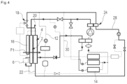
- the refrigerant loop is shown in solid lines and the heat transfer fluid loop is shown in dotted lines.
- Figures 2 to 4 for each of the loops, the portions traversed by their respective fluid are in solid lines and the portions without fluid circulation in dotted lines. Furthermore, the circulation of the refrigerant is illustrated by indicating its direction of circulation by arrows. Solid lines of different thickness are also used. More precisely, the thickest lines correspond to high pressure portions, the line of intermediate thickness to intermediate portions and the thinnest lines to low pressure portions of the refrigerant loop.
- the refrigerant is, for example, a fluid capable of changing from liquid to gaseous phase and vice versa under the temperature and pressure conditions of the circuit. It may be a fluid known as R134a or a fluid known as R1234yf. It may also be a fluid remaining essentially in the gaseous state such as R744.
- the heat transfer fluid is, for example, a liquid, in particular water with added antifreeze such as glycol.
- Said circuit comprises first 2, second 4 and third 6 heat exchangers.
- Said circuit is configured to allow a series circulation of the refrigerant in the first 2 and third 6 exchangers and a circulation of the heat transfer fluid in the second exchanger 4.
- the first and third exchangers are in the refrigerant circulation loop and the second exchanger 4 is in the heat transfer fluid loop.
- first 2 and the third 6 exchangers are located in series in a direction of circulation of an air flow, illustrated by an arrow marked F1, intended to pass through them in this order.
- the third heat exchanger 6 is intended to be passed through by an ambient air flow, in other words air not yet heated by the first 2 and/or the second 4 exchangers.
- this is the same air flow F1 as that passing through the first and second exchangers 2, 4, the air flow F1 then passing through, in this order, the third exchanger 6, the first exchanger 2 and the second exchanger 4.
- the second exchanger 4 can be used to cool other components using the heat transfer fluid, this with the possibility of having a large frontal surface because it is located downstream of the first exchanger 2 in the direction of circulation of the air flow. This frontal surface therefore does not interfere with that of the third exchanger 6 which is located either upstream of the first exchanger 2 in the direction of circulation of the air flow or elsewhere in the vehicle provided that it can be crossed by an ambient air flow.
- the circuit can be configured so that the series flow of the refrigerant in the first 2 and the third 6 exchangers does not occur systematically but only in certain operating modes. This is the case in the example illustrated where the series flow occurs in the operating modes of the figures 2 And 4 but not in the operating mode of the figure 3 .
- the first exchanger 2 is formed, for example, of a condenser or cooler of gas.
- the third exchanger 6 is configured, for example, to perform subcooling of said refrigerant after it has passed through the condenser or gas cooler.
- exchangers comprising a heat exchange bundle with tubes and spacers.
- the tubes are intended for the circulation of the refrigerant.
- the spacers are in contact with the tubes and are intended to be crossed by the air flow.
- Said condenser has one or more passes for circulation of the refrigerant.
- the circulation of the heat transfer fluid allows, for example, cooling of one or more elements of an electric drive train of the vehicle such as an electric motor 8, capable of setting said vehicle in motion, and an associated electric converter 10, intended to convert the direct electric current delivered by an electrical storage device into alternating current to power the electric motor 8.
- the heat transfer fluid circulation loop advantageously comprises a first branch 12 passing in this order according to the direction of circulation of the heat transfer fluid the electric converter 10 and the electric motor 8.
- the converter 10 and/or the motor 8 are not directly traversed by the heat transfer fluid but by an auxiliary fluid, said auxiliary fluid exchanging heat with the heat transfer fluid using a heat exchanger connected to the component in question by a specific auxiliary fluid circulation loop.
- Said circuit is further configured here so that the series circulation of the refrigerant in the first 2 and the third 6 exchangers allows a cooling, called rapid, of the electrical energy storage device and/or the heat treatment of a passenger compartment of the vehicle.
- the electrical energy storage device is not shown as such. It may be directly in contact with an element of the refrigerant circulation loop such as a cooler 14. Alternatively, it may be cooled by an auxiliary fluid itself exchanging heat with the refrigerant, for example using said cooler 14. In the illustrated embodiment, the associated operating mode, called rapid cooling of the electrical energy storage device, is encountered figure 4 .
- said first and second heat exchangers 2, 4 are intended to be positioned on the front of the vehicle, for example behind its grille. They advantageously have a substantially identical frontal surface, in particular so as to each occupy the largest available surface.
- frontal surface we mean the surface of the exchanger in a plane perpendicular to the air flow F1, that is to say, in a plane substantially parallel to the grille.
- said third exchanger 6 is also intended to be positioned at the front of the vehicle and crossed by the air flow F1. It is then located upstream of the first 2 and the second 4 exchangers according to the direction of circulation of the air flow.
- said third exchanger 6 has a frontal surface smaller than that of the first and/or second exchangers 2, 4.
- this characteristic may also apply when the third exchanger 6 is located in another location.
- said third exchanger 6 may be located, for example, in a wheel arch. Its frontal surface is then adapted to the space available.
- said circuit comprises a fourth exchanger 16 which is here arranged next to the third exchanger 6 so that the third 6 and the fourth 16 exchangers are crossed in parallel by said air flow F1.
- said third exchanger 6 and said fourth exchanger 16, taken together, have a front surface substantially identical to the front surface of said first 2 and second 4 heat exchangers.
- the second exchanger 4 is formed, for example, by a cooling radiator. It may be described as a low-temperature radiator.
- the fourth exchanger 16 is configured, for example, to perform additional cooling of said heat transfer fluid. It may be described as a very low-temperature exchanger.
- exchangers comprising a heat exchange bundle with tubes and spacers. The tubes are intended for the circulation of the cooling fluid. The spacers are in contact with the tubes and are intended to be crossed by the air flow.
- Said circuit is configured to furthermore selectively authorize circulation of the heat transfer fluid in the second exchanger 4, without passage through the fourth exchanger 16, as is the case in figure 4 , and a circulation of the heat transfer fluid in the second 4 and fourth 16 heat exchangers, as is the case in figures 2 And 3 .
- said fourth exchanger 16 is integrated into the heat transfer fluid circulation loop. When no circulation of heat transfer fluid takes place in the fourth exchanger 16, this promotes the efficiency of the first exchanger 2 because the air flow passing through the latter is then an air flow at ambient temperature, at least on the portion of said first exchanger 2 located opposite the fourth exchanger 16.
- the circulation of the heat transfer fluid in the second 4 and fourth 16 heat exchangers is carried out in series here. Alternatively, it is carried out in parallel.
- Said circuit further comprises at least one valve 18 making it possible, depending on the direction of circulation of said heat transfer fluid, to selectively direct the heat transfer fluid downstream of the second exchanger 4 towards said fourth exchanger 16, as in figures 2 And 3 , or directly to the rest of the circuit, as in the figure 4 .
- This is, for example, a three-way valve with here a first inlet, a second inlet and a common outlet.
- Said first inlet is connected, for example, to a portion 20 of a second branch 22 of the cooling fluid circulation loop comprising said second exchanger 4, said portion 20 making it possible to bypass said fourth exchanger 16 at the outlet of the second exchanger 4.
- Said second inlet is connected to the fourth heat exchanger 16.
- Said common outlet is connected in particular to the first branch 12 of said cooling fluid circulation loop.
- said valve 18 comprises a common inlet, a first outlet and a second outlet.
- the inlet is then connected to the second exchanger 4, the first outlet to the portion 20 of the second branch 22 of the cooling fluid circulation loop and the second outlet to the fourth heat exchanger 16.
- Said valve 18 is formed, in particular, by a thermostat and/or an electronically controlled valve making it possible to selectively connect the first and/or second input of said valve with the common output and/or the common input with the first and/or second output.
- said circuit is configured to selectively authorize circulation of the refrigerant fluid in the first exchanger 2, without passage in the third exchanger 6, as in the figure 3 , or the series circulation of the refrigerant in the first 2 and third 6 exchangers, as in figures 2 And 4 . It is thus possible not to systematically use the third exchanger 6, which can be advantageous for limiting pressure losses in the refrigerant loop when heat dissipation requirements are limited.
- Such an operating mode is for example used for so-called operational cooling of the electrical storage device, i.e. cooling requiring less heat dissipation than in the case of rapid recharging, and/or for heat treatment of the vehicle interior.
- This is for example the case for a operation in heat pump mode, as in figure 3 .
- calories are taken from the air flow F1 passing through the first exchanger 2 and returned, as will be developed below, to an air flow, illustrated F2, intended to enter the passenger compartment of the vehicle to heat it.
- Said circuit is thus configured so that the circulation of the refrigerant in the first heat exchanger 2, without passing through the third exchanger 6, allows such a result.
- said circuit comprises a fifth exchanger 24, called bi-fluid, configured to allow heat exchange between said refrigerant and said heat transfer fluid.
- a fifth exchanger is therefore located both in the refrigerant loop and the cooling fluid loop. It is, for example, a condenser, in particular a stacked plate condenser.
- said circuit in particular said heat transfer fluid circulation loop, comprises a heating radiator 26 intended to be traversed by the heat transfer fluid.
- Said circuit is configured so that the heat transfer fluid circulating in the two-fluid exchanger 24 circulates in said heating radiator 26, according to at least one operating mode of said circuit, in particular the heat pump mode mentioned above.
- the calories are taken from the air flow F1 passing through the first exchanger 2 and transmitted by said exchanger 2 to the refrigerant fluid. They are then transmitted to the cooling fluid by said fifth exchanger 24 and to the air flow F2 intended to enter the passenger compartment of the vehicle by the heating radiator 26.
- said circuit is configured so that, according to at least one operating mode, said fifth exchanger 24 is located upstream of said first exchanger 2 according to the direction of circulation of the refrigerant fluid.
- the operating modes in question are, for example, an air conditioning mode, encountered figure 2 according to the illustrated embodiment, and/or the rapid cooling mode of the electrical energy storage device (as a reminder illustrated figure 4 ).
- the refrigerant undergoes both pre-cooling in the fifth exchanger 24, cooling, possibly with phase change, in the first exchanger 2 and if necessary sub-cooling in the third exchanger 6.
- the enthalpy variation of the refrigerant is then optimized, which makes it possible to limit the power to be supplied to the refrigerant loop, for equivalent performance.
- Said circuit may include a bottle, not illustrated, configured for a phase separation between a vapor phase and a liquid phase of said refrigerant.
- Said bottle is for example integrated into said first exchanger 2 which may then include or not, within its bundle, one or more subcooling passes. This subcooling is added to that provided by the third exchanger 6, in the operating modes in which a series circulation in the first 2 and third 6 exchangers occurs.
- said bottle is located between said first 2 and third 6 exchangers, according to the direction of circulation of the refrigerant.
- Said bottle is advantageously provided with a filter and/or a desiccant.
- the cooling fluid circulation loop comprises the first 8 and the second branch 22 already mentioned as well as a third branch 28 and a fourth branch 30, all of said branches 12, 22, 28, 30 being located parallel to each other.
- the first branch 12 comprises the electric converter 10 and the electric motor 8. It also comprises a first pump 32 for circulating the cooling fluid.
- the second branch 22 comprises the second exchanger 4 and the three-way valve 18. In parallel with its portion 20, it further comprises a sub-branch 34 provided with said fourth exchanger 16.
- the third branch 28 comprises the dual-fluid exchanger 26 and a second pump 36 for circulating the heat transfer fluid.
- the fourth branch 30 comprises a first two-way valve 38 and the heating radiator 26. It further comprises here an electric heating device 40 of the cooling fluid, intended to be used in combination with the heating radiator 26, if necessary.
- Said cooling fluid circulation loop may also comprise a second two-way valve 42, located between, on the one hand, the first 12 and second 22 branches and, on the other hand, the third 28 and fourth 30 branches on the downstream side relative to the second pump 36.
- Said circuit in particular said refrigerant circulation loop, comprises a compression device 50 for circulating the refrigerant.
- the compression device 50 may take the form of an electric compressor, i.e. a compressor which comprises a compression mechanism, an electric motor and possibly a controller.
- said refrigerant circulation loop comprises said two-fluid exchanger 24, a third two-way valve 52, said first exchanger 2, said third exchanger 6, a non-return valve 54, a first pass 56 of an internal exchanger 58, and in parallel with each other in respective branches, an evaporator 58 and the cooler 14, then an accumulator 60 and a second pass 62 of the internal exchanger 58.
- These components follow one another in this order according to a sub-loop in which the refrigerant returns to the compression device 50 after passing through the second pass 62 of the internal exchanger 58.
- Said circuit further comprises first 64, second 66 and third 80 diversion branches making it possible to modify the path of the refrigerant fluid.
- the first diversion branch 64 is located between a first point of divergence 68 and a first point of convergence 70.
- the first point of divergence 68 is located between the third two-way valve 52 and the first exchanger 2.
- the first point of convergence 70 is located between the non-return valve 54 and the first pass 56 of the internal exchanger 58.
- Said first diversion branch 64 comprises a first expansion member 76.
- Said expansion member is configured to selectively fully open said first diversion branch 64, fully close said first diversion branch 64 or operate an expansion of the refrigerant fluid circulating in said first diversion branch 64.
- the second diversion branch 66 is located between a second point of divergence 72 and a second point of convergence 74.
- the second point of divergence 72 is located between the two-fluid exchanger 24 and the third two-way valve 52.
- the second point of convergence 74 is located between the first pass 56 of the internal exchanger 58 and a portion, here a point, of the sub-loop mentioned above and allowing the parallel supply of the evaporator 58 and the cooler 14.
- Said second diversion branch 66 comprises a fourth two-way valve 78.
- the third diversion branch 80 is located between a third point of divergence 82 and a third point of convergence 84.
- the third point of divergence 82 is located between the first exchanger 2 and the third exchanger 6.
- the third point of convergence 84 is located between, on the one hand, a portion, here a point, of the sub-loop mentioned above and making it possible to collect in parallel the refrigerant fluid leaving the evaporator 58 and the cooler 14 and, on the other hand, the accumulator 60.
- Said third diversion branch 80 comprises a fifth two-way valve 86.
- the refrigerant circulation loop also includes second 88 and third 90 expansion members respectively located upstream of the evaporator 58 and the cooler 14 in the associated branches. Said expansion members are configured to selectively fully open said branches, fully close said branches or operate an expansion of the refrigerant fluid circulating in said branches.
- the circuit provides both an air conditioning mode and a mode in which the heat released by the element(s) 8, 10 of the electric powertrain of the vehicle is dissipated so as to cool the cooling fluid below the maximum admissible temperature Tmax downstream of the converter 10, including under conditions of use such as operation at maximum power.
- the coolant circulates in the first branch 12, the second branch 22, passing through the sub-branch 34, and in the third branch 28 but not in the fourth branch 30.
- the three-way valve 18 is open so as to circulate the coolant in the fourth exchanger 16, as explained above.
- the first two-way valve 38 is closed.
- the second two-way valve 42 is open.
- the first and/or second pumps 32, 36 are active.
- the cooling fluid circulates in a loop in the first and second branches 12, 22 so that the heat released by the elements of the drive train 8, 10 is dissipated into the air by the second and fourth exchangers 4, 16. If the cooling requirements remain limited, the cooling fluid can pass through the bypass portion 20 rather than through the sub-branch 34.
- the cooling fluid also circulates in the third branch 28, in parallel with the first branch 12, to allow the cooling of the refrigerant at the level of the two-fluid exchanger 24.
- the fourth two-way valve 52 is open and said second 88 and third 90 expansion members operate as an expansion valve.
- the first expansion member 76 is closed as well as the fourth two-way valve 78 and the fifth two-way valve 86.
- the heat dissipation ensured by the dual-fluid exchanger 24 in the cooling fluid and by the first 2 and third 6 exchangers in the air flow F1 makes it possible on the one hand to cool the electrical energy storage device, thanks to the cooler 14 and on the other hand to air-condition the passenger compartment of the vehicle via the evaporator 58 which cools the air flow F2, in particular during vehicle driving phases.
- the circuit provides a heat pump mode, here without cooling of the electrical storage device although a heat pump mode remains compatible with cooling operational of said storage device with the illustrated circuit.
- the coolant circulates in the first branch 12, the second branch 22, passing through the sub-branch 34, in the third branch 28 and in the fourth branch 30.
- the three-way valve 18 is open so as to circulate the coolant in the fourth exchanger 16, as explained above.
- the first two-way valve 38 and the second two-way valve 42 are open.
- the first and/or second pumps 32, 36 are active. In this way, the coolant circulates in a loop in the third and fourth branches 28, 30 so that the heat transmitted by the two-fluid exchanger 24 is dissipated in the air flow F2 by the heating radiator 26 for heating the passenger compartment of the vehicle.
- the circulation in the first branch 12 takes place in parallel with the circulation in the third branch 28 so as to recover the heat released by the elements of the electric traction chain 8, 10.
- the circulation of the cooling fluid in the second branch 22 may be cut off, here using said three-way valve 18.
- the refrigerant follows a different path from that of the sub-loop mentioned above.
- the third two-way valve 52 is closed as well as said second 88 and third 90 expansion members.
- the first expansion member 76 operates as an expander.
- the fourth two-way valve 78 and the fifth two-way valve 86 are open. Downstream of the compression device 50, the refrigerant thus passes successively through said two-fluid exchanger 24, the fifth two-way valve 52, the first pass 56 of the internal exchanger 58, the first expansion member 76, said first exchanger 2, said sixth valve 86 then the accumulator 60 and a second pass 62 of the internal exchanger 58.
- the first exchanger 2 then operates as an evaporator and captures heat from the air flow F1 which will be transmitted to the air flow F2 by the two-fluid exchanger 24 and the heating radiator 26.
- the circuit ensures rapid cooling of the energy storage device. Such operation typically takes place when the vehicle is stationary and other cooling requirements or heating requirements are generally low.
- the coolant circulates in the second branch 22, passing through the portion 20, and in the third branch 28 but does not circulate in either the first branch 12 or the fourth branch 30.
- the three-way valve 18 is open so as to circulate the coolant in the portion 20, as explained above.
- the first two-way valve 38 is closed.
- the second two-way valve 42 is open.
- the first pump 32 is inactive while the second pump 36 is active.
- the cooling fluid circulates in a loop in the second branch 12 and the third branch 28 so as to ensure a minimum flow rate of cooling fluid in the two-fluid exchanger 24 so that said cooling fluid does not boil under the effect of the heat dissipated by the refrigerant.
- the refrigerant follows the same path as in the case of the figure 2 , namely the sub-loop mentioned above.
- the heat dissipation ensured by the bi-fluid exchanger 24 in the cooling fluid and by the first 2 and third 6 exchangers in the air flow F1 makes it possible to ensure rapid cooling of the energy storage device by the cooler 14.
- Another aspect not forming part of the invention relates to a method for controlling a thermal regulation circuit of a vehicle.
- This may be the circuit described above provided that it includes said fourth exchanger 16, then referred to as an additional exchanger according to this aspect of the invention. That being said, more broadly, said method may also be applied to configurations without the third exchanger 6, the rest of the circuit then remaining advantageously identical.
- said additional heat exchanger 16 preferably has a front surface substantially identical to that of the first and/or second heat exchangers 2, 4.
- said method comprises a step in which a flow rate of the heat transfer fluid is generated or increased in the additional exchanger 16, depending on operating modes of the circuit.
- a flow rate of the heat transfer fluid is generated or increased in the additional exchanger 16, depending on operating modes of the circuit.
- said method comprises a step in which a circulation of the heat transfer fluid in the second exchanger 4 is selectively authorized, without passage through the additional exchanger 16, and a circulation of the heat transfer fluid in the second exchanger 4 and in the additional heat exchanger 16. In this way, the heat dissipation power is modulated according to the needs.
- said method comprises a step of controlling at least one parameter relating to the heat transfer fluid. This is in particular the temperature of the heat transfer fluid.
- the step in which the flow rate of heat transfer fluid in the additional exchanger 16 is generated or increased is carried out as a function of a value of said parameter, in particular by comparing the value of the parameter with a threshold value.
- the step in which the flow rate of heat transfer fluid in the additional exchanger is generated or increased occurs if the temperature of the heat transfer fluid is slightly lower, equal to or higher than the maximum admissible temperature.
- Said step in which the flow rate of heat transfer fluid in the additional exchanger is generated or increased here comprises a step of opening/closing said three-way valve 18, in all or nothing and/or partially.
- the order of said sub-steps can also be modified depending on the speed of the vehicle, in particular depending on the speed of the vehicle relative to a threshold speed.
- sub-step (c) is first carried out, then sub-step (b) if this remains insufficient in relation to a target to be reached.
- Sub-step (a) has little effect.
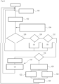
- a first step 100 information on the vehicle is acquired according to a first step 100.
- the flow rate and temperature of the coolant are measured as well as the speed and temperature of the air flow F1 according to a second step 102.
- Information on the refrigerant circulation loop is acquired according to a third step 104 and then a test is carried out to check whether the temperature of the coolant is greater than a setpoint, possibly taking into account a measurement uncertainty, according to a fourth step 106.
- step 106 If the result of the fourth step 106 is negative, monitoring continues by looping back to the first step 100.
- a test is then carried out to check whether a rotation speed of the motor-fan unit is maximum, according to a fifth step 108.
- step 108 If the result of the fifth step 108 is negative, the speed of the motor-fan unit is then increased, according to a sixth step 110, and monitoring continues by looping back to the first step 100.
- a test is then carried out to check whether the shutters are opened to the maximum, according to a seventh step 112.
- the opening of the shutters is then increased, according to an eighth step 114, and the monitoring continues by looping back to the first step 100.
- a test is then carried out to check whether the flow rate in the additional heat exchanger 16 is maximum, according to a ninth step 116.
- the flow rate in the additional heat exchanger 16 is then increased, in particular using the three-way valve 18 mentioned above, this according to one or more tenth steps 118, and the monitoring continues by looping back to the first step 100.
- sub-step (a) when the vehicle is stationary and/or at a speed lower than the threshold speed, sub-step (b) is carried out, then if this remains insufficient in relation to the setpoint to be reached, sub-step (c) is carried out.
- said threshold speed of the vehicle namely the speed below or above which the order of steps (a), (b) and (c) varies, may be adjusted according to the ambient temperature.
- the invention also relates to a heat exchange module, not illustrated, comprising the first 2, second 4 as well as third 6 and/or fourth 16 heat exchangers.
- Said module may further advantageously comprise the three-way valve 18.
- the module comprises, for example, a frame on which said first 2, second 4, third 6, fourth 16 heat exchangers and/or said three-way valve 18 are fixed.
- Said frame is configured to be fixed directly or indirectly to a chassis of the vehicle.
Landscapes
- Engineering & Computer Science (AREA)
- Physics & Mathematics (AREA)
- Thermal Sciences (AREA)
- Mechanical Engineering (AREA)
- Life Sciences & Earth Sciences (AREA)
- Sustainable Development (AREA)
- Sustainable Energy (AREA)
- Electric Propulsion And Braking For Vehicles (AREA)
- Air-Conditioning For Vehicles (AREA)
- Cooling, Air Intake And Gas Exhaust, And Fuel Tank Arrangements In Propulsion Units (AREA)
- Heat-Exchange Devices With Radiators And Conduit Assemblies (AREA)
Claims (8)
- Wärmeregulationskreislauf für ein Fahrzeug, wobei dieser Kreislauf einen ersten (2) und einen zweiten (4) Wärmetauscher umfasst, die in einer Strömungsrichtung eines Luftstroms, der dazu bestimmt ist, sie in dieser Reihenfolge zu durchqueren, in Reihe angeordnet sind, wobei der Kreislauf einen dritten Wärmetauscher (6) umfasst, der dazu bestimmt ist, von einem Umgebungsluftstrom durchquert zu werden, wobei der Kreislauf dafür ausgelegt ist, eine Strömung in Reihe eines Kältemittels im ersten (2) und dritten (6) Wärmetauscher und eine Strömung eines Wärmeträgerfluids im zweiten Wärmetauscher (4) zu ermöglichen, dadurch gekennzeichnet, dass der erste (2) und zweite (4) Wärmetauscher dazu bestimmt sind, an der Vorderseite des Fahrzeugs positioniert zu werden, und eine im Wesentlichen identische vordere Fläche aufweisen, wobei der dritte Wärmetauscher (6) dazu bestimmt ist, an der Vorderseite des Fahrzeugs positioniert zu werden, stromaufwärts des ersten (2) und zweiten (4) Wärmetauschers in der Strömungsrichtung des sie durchquerenden Luftstroms.
- Kreislauf nach Anspruch 1, welcher dafür ausgelegt ist, dass die Strömung des Wärmeträgerfluids eine Kühlung eines oder mehrerer Elemente (8, 10) eines elektrischen Antriebsstranges des Fahrzeugs ermöglicht, und dafür, dass die Strömung in Reihe des Kältemittels im ersten (2) und dritten (6) Wärmetauscher eine Kühlung, Schnellkühlung genannt, einer elektrischen Energiespeichervorrichtung und/oder die Wärmebehandlung eines Innenraumes des Fahrzeugs ermöglicht.
- Kreislauf nach einem der vorhergehenden Ansprüche, welcher einen vierten Wärmetauscher (16) umfasst, wobei der Kreislauf dafür ausgelegt ist, außerdem selektiv eine Strömung des Wärmeträgerfluids im zweiten Wärmetauscher (4) und eine Strömung des Wärmeträgerfluids im zweiten (4) und vierten (16) Wärmetauscher zu ermöglichen.
- Kreislauf nach dem vorhergehenden Anspruch, wobei der dritte Wärmetauscher (6) und der vierte Wärmetauscher (16) in der Strömungsrichtung des Luftstroms nebeneinander angeordnet sind.
- Kreislauf nach einem der vorhergehenden Ansprüche, welcher dafür ausgelegt ist, selektiv eine Strömung des Kältemittels im ersten Wärmetauscher (2) oder die Strömung in Reihe des Kältemittels im ersten (2) und dritten (6) Wärmetauscher zu ermöglichen.
- Kreislauf nach dem vorhergehenden Anspruch, welcher dafür ausgelegt ist, dass die Strömung des Kältemittels im ersten Wärmetauscher (2) eine Kühlung, Betriebskühlung genannt, der elektrischen Speichervorrichtung und/oder eine Wärmebehandlung eines Innenraumes des Fahrzeugs ermöglicht.
- Kreislauf nach einem der vorhergehenden Ansprüche, welcher einen fünften Wärmetauscher (24) umfasst, Bi-Fluid-Wärmetauscher genannt, der dafür ausgelegt ist, einen Wärmeaustausch zwischen dem Kältemittel und dem Wärmeträgerfluid zu ermöglichen, und einen Heizkörper (26), der dazu bestimmt ist, von dem Wärmeträgerfluid durchströmt zu werden, wobei der Kreislauf dafür ausgelegt ist, dass das Wärmeträgerfluid, das durch den Bi-Fluid-Wärmetauscher (24) strömt, in mindestens einer Betriebsart des Kreislaufs durch den Heizkörper (26) strömt.
- Wärmeaustauschmodul, welches den ersten, den zweiten und den dritten Wärmetauscher des Kreislaufs der vorhergehenden Ansprüche umfasst.
Applications Claiming Priority (2)
| Application Number | Priority Date | Filing Date | Title |
|---|---|---|---|
| FR1909878A FR3100491A1 (fr) | 2019-09-09 | 2019-09-09 | Circuit de fluide refrigerant pour vehicule et procede de contrôle d’un tel circuit |
| PCT/FR2020/051542 WO2021048490A1 (fr) | 2019-09-09 | 2020-09-07 | Circuit de fluide refrigerant pour vehicule et procede de contrôle d'un tel circuit |
Publications (2)
| Publication Number | Publication Date |
|---|---|
| EP4028271A1 EP4028271A1 (de) | 2022-07-20 |
| EP4028271B1 true EP4028271B1 (de) | 2025-03-05 |
Family
ID=68654772
Family Applications (1)
| Application Number | Title | Priority Date | Filing Date |
|---|---|---|---|
| EP20786021.4A Active EP4028271B1 (de) | 2019-09-09 | 2020-09-07 | Kältemittelkreislauf für ein fahrzeug |
Country Status (5)
| Country | Link |
|---|---|
| US (1) | US12384223B2 (de) |
| EP (1) | EP4028271B1 (de) |
| CN (1) | CN114364552A (de) |
| FR (1) | FR3100491A1 (de) |
| WO (1) | WO2021048490A1 (de) |
Families Citing this family (4)
| Publication number | Priority date | Publication date | Assignee | Title |
|---|---|---|---|---|
| ES2865388T3 (es) * | 2018-06-27 | 2021-10-15 | Abb Schweiz Ag | Equipo de carga de vehículo eléctrico |
| FR3100482B1 (fr) * | 2019-09-09 | 2021-07-30 | Valeo Systemes Thermiques | Circuit de fluide refrigerant pour vehicule et procede de contrôle d’un tel circuit |
| FR3100491A1 (fr) * | 2019-09-09 | 2021-03-12 | Valeo Systemes Thermiques | Circuit de fluide refrigerant pour vehicule et procede de contrôle d’un tel circuit |
| CN117295624A (zh) * | 2021-03-15 | 2023-12-26 | 法雷奥热系统公司 | 热调节系统 |
Family Cites Families (58)
| Publication number | Priority date | Publication date | Assignee | Title |
|---|---|---|---|---|
| US5408843A (en) * | 1994-03-24 | 1995-04-25 | Modine Manufacturing Co. | Vehicular cooling system and liquid cooled condenser therefor |
| JPH1076841A (ja) * | 1996-09-06 | 1998-03-24 | Calsonic Corp | ヒートポンプ式自動車用空気調和装置 |
| EP0842799A3 (de) * | 1996-11-15 | 2003-03-05 | Calsonic Kansei Corporation | Wärmepumpenartige Klimaanlage für ein Kraftfahrzeug |
| JP2006002631A (ja) * | 2004-06-16 | 2006-01-05 | Toyota Motor Corp | 熱交換装置およびこれを搭載するハイブリッド車。 |
| FR2946415B1 (fr) * | 2009-06-05 | 2013-12-27 | Valeo Systemes Thermiques | Systeme de gestion thermique comprenant une boucle de climatisation et un circuit de fluide caloporteur |
| DE102009060860B4 (de) * | 2009-12-30 | 2024-06-27 | Konvekta Aktiengesellschaft | Klimatisierungssystem für ein Fahrzeug sowie Verfahren zum Temperieren |
| JP5994588B2 (ja) * | 2011-12-05 | 2016-09-21 | 株式会社デンソー | 熱交換システム |
| FR2984471B1 (fr) * | 2011-12-15 | 2013-11-29 | Valeo Systemes Thermiques | Dispositif de conditionnement thermique d'une chaine de traction et d'un habitacle de vehicule |
| JP5669778B2 (ja) | 2012-03-16 | 2015-02-18 | 株式会社日本自動車部品総合研究所 | 冷却装置およびそれを備える車両 |
| JP5983187B2 (ja) * | 2012-08-28 | 2016-08-31 | 株式会社デンソー | 車両用熱管理システム |
| FR2995669B1 (fr) | 2012-09-14 | 2018-05-25 | Valeo Systemes Thermiques | Dispositif de conditionnement thermique d'un habitacle d'un vehicule electrique |
| FR3008930B1 (fr) | 2013-07-26 | 2017-04-07 | Valeo Systemes Thermiques | Dispositif de conditionnement thermique pour vehicule automobile comprenant une machine electrique servant a l'entrainement dudit vehicule |
| FR3014754B1 (fr) | 2013-12-12 | 2016-01-01 | Renault Sas | Systeme de chauffage, ventilation et climatisation d'air pour vehicule hybride |
| DE102015220623B4 (de) * | 2015-10-22 | 2022-01-27 | Bayerische Motoren Werke Aktiengesellschaft | Wärmesystem für ein Elektro- oder Hybridfahrzeug |
| DE102015016241B4 (de) * | 2015-12-16 | 2023-05-17 | Cellcentric Gmbh & Co. Kg | Elektrisch angetriebenes Fahrzeug mit einem Kühlsystem |
| DE102015122721B4 (de) * | 2015-12-23 | 2019-09-05 | Hanon Systems | Klimatisierungssystem eines Kraftfahrzeugs und Verfahren zum Betreiben des Klimatisierungssystems |
| JP6590321B2 (ja) * | 2016-03-25 | 2019-10-16 | パナソニックIpマネジメント株式会社 | 車両用空調装置 |
| KR101836272B1 (ko) * | 2016-06-20 | 2018-03-08 | 현대자동차 주식회사 | 차량용 히트 펌프 시스템 |
| KR102626014B1 (ko) * | 2016-12-07 | 2024-01-17 | 한온시스템 주식회사 | 차량용 열관리 시스템 |
| CN108571834B (zh) * | 2017-03-08 | 2021-09-28 | 杭州三花研究院有限公司 | 一种热管理系统 |
| DE102017109309A1 (de) * | 2017-05-02 | 2018-11-08 | Hanon Systems | Klimatisierungssystem eines Kraftfahrzeugs und Verfahren zum Betreiben des Klimatisierungssystems |
| DE102018118118A1 (de) * | 2017-08-23 | 2019-02-28 | Hanon Systems | Klimatisierungssystem eines Kraftfahrzeugs und Verfahren zum Betreiben des Klimatisierungssystems |
| DE102017120615A1 (de) * | 2017-09-07 | 2019-03-07 | Volkswagen Aktiengesellschaft | Kraftfahrzeug mit einem Kühlsystem |
| DE102017125170A1 (de) * | 2017-10-26 | 2019-05-02 | Borgward Trademark Holdings Gmbh | Wärememanagementsystem für ein elektrofahrzeug und ein elektrofahrzeug |
| US11021037B2 (en) * | 2017-11-07 | 2021-06-01 | Hanon Systems | Thermal management system |
| DE102017220376A1 (de) * | 2017-11-15 | 2019-05-16 | Bayerische Motoren Werke Aktiengesellschaft | Kühlsystem für ein Kraftfahrzeug und Kraftfahrzeug mit einem solchen Kühlsystem |
| DE102019109796B4 (de) * | 2018-05-31 | 2025-07-10 | Hanon Systems | Wärmestrommanagementvorrichtung und Verfahren zum Betreiben einer Wärmestrommanagementvorrichtung |
| JP7117945B2 (ja) * | 2018-08-30 | 2022-08-15 | サンデン株式会社 | 車両空調装置用ヒートポンプシステム |
| FR3086334B1 (fr) * | 2018-09-26 | 2020-09-04 | Valeo Systemes Thermiques | Circuit de fluide refrigerant pour vehicule |
| DE102018219859B4 (de) * | 2018-11-20 | 2020-09-03 | Audi Ag | Kälteanlage für ein Fahrzeug sowie Fahrzeug mit einer Kälteanlage |
| DE102018129393B4 (de) * | 2018-11-22 | 2022-10-06 | Hanon Systems | Klimatisierungssystem eines Kraftfahrzeugs und Verfahren zum Betreiben des Klimatisierungssystems |
| KR102633864B1 (ko) * | 2018-12-06 | 2024-02-05 | 현대자동차 주식회사 | 차량용 배터리 냉각 시스템 |
| DE102020100428B4 (de) * | 2019-02-06 | 2024-10-31 | Magna Steyr Fahrzeugtechnik Gmbh & Co Kg | Klimatisierungs- und Batteriekühlanordnung mit hoher Kälteleistung und passiver Batteriekühlung sowie Verfahren zum Betreiben einer Klimatisierungs- und Batteriekühlanordnung |
| US11110778B2 (en) * | 2019-02-11 | 2021-09-07 | Ford Global Technologies, Llc | Heat pump secondary coolant loop heat exchanger defrost system for a motor vehicle |
| US11214115B2 (en) * | 2019-06-03 | 2022-01-04 | Proterra Inc. | Temperature management systems and methods for electric vehicle |
| DE102019120229A1 (de) * | 2019-07-26 | 2021-01-28 | Bayerische Motoren Werke Aktiengesellschaft | Wärmemanagementsystem für ein Kraftfahrzeug, Verfahren zum Wärmemanagement eines Kraftfahrzeugs und Kraftfahrzeug mit einem Wärmemanagementsystem |
| FR3100482B1 (fr) * | 2019-09-09 | 2021-07-30 | Valeo Systemes Thermiques | Circuit de fluide refrigerant pour vehicule et procede de contrôle d’un tel circuit |
| FR3100491A1 (fr) * | 2019-09-09 | 2021-03-12 | Valeo Systemes Thermiques | Circuit de fluide refrigerant pour vehicule et procede de contrôle d’un tel circuit |
| EP3984794B1 (de) * | 2019-09-19 | 2024-12-18 | Hangzhou Sanhua Research Institute Co., Ltd. | Wärmeverwaltungssystem |
| FR3104495A1 (fr) * | 2019-12-16 | 2021-06-18 | Valeo Systemes Thermiques | Circuit de fluide réfrigérant pour véhicule adapté à une charge rapide d’un dispositif de stockage |
| DE102020201349A1 (de) * | 2020-02-04 | 2021-08-05 | Volkswagen Aktiengesellschaft | Kältemittelkreislaufanordnung und Verfahren zum Betrieb einer Kältemittelkreislaufanordnung |
| US20230356564A1 (en) * | 2020-09-30 | 2023-11-09 | Sanhua Holding Group Co., Ltd. | Thermal management system with improved working efficiency of compressor |
| CN114312205B (zh) * | 2021-02-05 | 2023-12-08 | 华为数字能源技术有限公司 | 热管理系统、热管理系统的控制方法与电动汽车 |
| FR3120118A1 (fr) * | 2021-02-23 | 2022-08-26 | Valeo Systemes Thermiques | Procédé de régulation d’un circuit de fluide réfrigérant |
| CN117295624A (zh) * | 2021-03-15 | 2023-12-26 | 法雷奥热系统公司 | 热调节系统 |
| US11548349B2 (en) * | 2021-06-02 | 2023-01-10 | Guangzhou Automobile Group Co., Ltd. | Thermal management system and electric vehicle having the same |
| US11780287B2 (en) * | 2021-06-24 | 2023-10-10 | Guangzhou Automobile Group Co., Ltd. | Thermal management system and electric vehicle having the same |
| AT525232A1 (de) * | 2021-06-28 | 2023-01-15 | Avl List Gmbh | Heizungs- und Klimaanlage |
| CN116252621B (zh) * | 2021-09-30 | 2024-09-10 | 比亚迪股份有限公司 | 热管理系统和具有其的车辆 |
| US11919368B2 (en) * | 2021-10-07 | 2024-03-05 | Ford Global Technologies, Llc | Heat pump for a vehicle |
| US11912105B2 (en) * | 2021-10-07 | 2024-02-27 | Ford Global Technologies, Llc | Heat pump for a vehicle |
| US11987098B2 (en) * | 2021-10-26 | 2024-05-21 | Ford Global Technologies, Llc | Heat pump for a vehicle |
| US12441160B2 (en) * | 2021-11-09 | 2025-10-14 | GM Global Technology Operations LLC | Vehicle cabin and rechargeable energy storage system heating |
| US20230142706A1 (en) * | 2021-11-09 | 2023-05-11 | GM Global Technology Operations LLC | Vehicle cabin and rechargeable energy storage system thermal management system |
| KR20230090755A (ko) * | 2021-12-15 | 2023-06-22 | 현대자동차주식회사 | 차량의 통합 열관리 시스템 |
| KR20230143006A (ko) * | 2022-04-04 | 2023-10-11 | 현대자동차주식회사 | 차량의 열관리 시스템 및 그 제어방법 |
| KR20230158861A (ko) * | 2022-05-12 | 2023-11-21 | 현대자동차주식회사 | 연료전지 차량의 통합열관리 시스템 |
| US11852068B1 (en) * | 2022-06-06 | 2023-12-26 | L & M Radiator, Inc. | Hybrid heat transfer assembly |
-
2019
- 2019-09-09 FR FR1909878A patent/FR3100491A1/fr not_active Ceased
-
2020
- 2020-09-07 EP EP20786021.4A patent/EP4028271B1/de active Active
- 2020-09-07 WO PCT/FR2020/051542 patent/WO2021048490A1/fr not_active Ceased
- 2020-09-07 US US17/641,222 patent/US12384223B2/en active Active
- 2020-09-07 CN CN202080062845.7A patent/CN114364552A/zh active Pending
Also Published As
| Publication number | Publication date |
|---|---|
| CN114364552A (zh) | 2022-04-15 |
| US12384223B2 (en) | 2025-08-12 |
| WO2021048490A1 (fr) | 2021-03-18 |
| FR3100491A1 (fr) | 2021-03-12 |
| US20240042829A1 (en) | 2024-02-08 |
| EP4028271A1 (de) | 2022-07-20 |
Similar Documents
| Publication | Publication Date | Title |
|---|---|---|
| EP4028271B1 (de) | Kältemittelkreislauf für ein fahrzeug | |
| FR3074272B1 (fr) | Circuit de gestion thermique d'un vehicule hybride ou electrique | |
| EP3856555B1 (de) | Kühlmittelkreislauf für ein fahrzeug | |
| EP3924673B1 (de) | Thermisches managementgerät für elektrische oder hybridmotorfahrzeuge | |
| EP4028275B1 (de) | Verfahren zum steuern eines kühlmittelkreislaufs für ein fahrzeug | |
| EP3807109B1 (de) | Wärmebehandlungssystem für fahrzeuge | |
| WO2019155179A1 (fr) | Systeme de refroidissement d'au moins une batterie de véhicule automobile | |
| EP3746317A1 (de) | Kältemittelkreislauf für ein fahrzeug | |
| WO2022128836A1 (fr) | Systeme de traitement thermique d'un vehicule | |
| EP4422894A1 (de) | Wärmeverwaltungssystem für ein hybrid- oder elektrofahrzeug | |
| FR3053288A1 (fr) | Circuit de climatisation reversible de vehicule automobile et procedes de fonctionnement | |
| FR3082455A1 (fr) | Systeme de traitement thermique pour vehicule | |
| WO2021249934A1 (fr) | Dispositif de gestion thermique d'un véhicule automobile électrique ou hybride comportant un circuit de fluide caloporteur | |
| EP4255746B1 (de) | Kältemittelkreislauf mit einem speicherbypasszweig | |
| WO2019020954A1 (fr) | Procede de gestion d'un circuit de climatisation inversible indirect de vehicule automobile | |
| WO2025078398A1 (fr) | Dispositif et procede de thermoregulation, notamment pour vehicule automobile | |
| EP4601895A1 (de) | Wärmeverwaltungssystem für ein hybrid- oder elektrofahrzeug | |
| FR3127720A1 (fr) | Systeme et procede de conditionnement thermique pour vehicule automobile | |
| FR3150575A1 (fr) | Dispositif et procédé de thermorégulation, notamment pour véhicule automobile | |
| WO2023025898A1 (fr) | Dispositif de gestion thermique des batteries pour véhicule électrique ou hybride | |
| WO2025242564A1 (fr) | Dispositif de gestion thermique des batteries pour véhicule électrique ou hybride | |
| WO2025087989A1 (fr) | Dispositif de gestion thermique des batteries pour vehicule electrique ou hybride | |
| WO2025153649A1 (fr) | Dispositif de gestion thermique des batteries pour véhicule électrique ou hybride | |
| WO2023072586A1 (fr) | Systeme de gestion thermique pour vehicule hybride ou electrique | |
| EP4396012A1 (de) | Wärmeverwaltungsvorrichtung für batterien für ein elektro- oder hybridfahrzeug |
Legal Events
| Date | Code | Title | Description |
|---|---|---|---|
| STAA | Information on the status of an ep patent application or granted ep patent |
Free format text: STATUS: UNKNOWN |
|
| STAA | Information on the status of an ep patent application or granted ep patent |
Free format text: STATUS: THE INTERNATIONAL PUBLICATION HAS BEEN MADE |
|
| PUAI | Public reference made under article 153(3) epc to a published international application that has entered the european phase |
Free format text: ORIGINAL CODE: 0009012 |
|
| STAA | Information on the status of an ep patent application or granted ep patent |
Free format text: STATUS: REQUEST FOR EXAMINATION WAS MADE |
|
| 17P | Request for examination filed |
Effective date: 20220408 |
|
| AK | Designated contracting states |
Kind code of ref document: A1 Designated state(s): AL AT BE BG CH CY CZ DE DK EE ES FI FR GB GR HR HU IE IS IT LI LT LU LV MC MK MT NL NO PL PT RO RS SE SI SK SM TR |
|
| DAV | Request for validation of the european patent (deleted) | ||
| DAX | Request for extension of the european patent (deleted) | ||
| P01 | Opt-out of the competence of the unified patent court (upc) registered |
Effective date: 20230528 |
|
| GRAP | Despatch of communication of intention to grant a patent |
Free format text: ORIGINAL CODE: EPIDOSNIGR1 |
|
| STAA | Information on the status of an ep patent application or granted ep patent |
Free format text: STATUS: GRANT OF PATENT IS INTENDED |
|
| INTG | Intention to grant announced |
Effective date: 20240924 |
|
| GRAS | Grant fee paid |
Free format text: ORIGINAL CODE: EPIDOSNIGR3 |
|
| GRAA | (expected) grant |
Free format text: ORIGINAL CODE: 0009210 |
|
| STAA | Information on the status of an ep patent application or granted ep patent |
Free format text: STATUS: THE PATENT HAS BEEN GRANTED |
|
| AK | Designated contracting states |
Kind code of ref document: B1 Designated state(s): AL AT BE BG CH CY CZ DE DK EE ES FI FR GB GR HR HU IE IS IT LI LT LU LV MC MK MT NL NO PL PT RO RS SE SI SK SM TR |
|
| REG | Reference to a national code |
Ref country code: GB Ref legal event code: FG4D Free format text: NOT ENGLISH |
|
| REG | Reference to a national code |
Ref country code: CH Ref legal event code: EP |
|
| REG | Reference to a national code |
Ref country code: IE Ref legal event code: FG4D Free format text: LANGUAGE OF EP DOCUMENT: FRENCH |
|
| REG | Reference to a national code |
Ref country code: DE Ref legal event code: R096 Ref document number: 602020047283 Country of ref document: DE |
|
| PG25 | Lapsed in a contracting state [announced via postgrant information from national office to epo] |
Ref country code: RS Free format text: LAPSE BECAUSE OF FAILURE TO SUBMIT A TRANSLATION OF THE DESCRIPTION OR TO PAY THE FEE WITHIN THE PRESCRIBED TIME-LIMIT Effective date: 20250605 |
|
| PG25 | Lapsed in a contracting state [announced via postgrant information from national office to epo] |
Ref country code: FI Free format text: LAPSE BECAUSE OF FAILURE TO SUBMIT A TRANSLATION OF THE DESCRIPTION OR TO PAY THE FEE WITHIN THE PRESCRIBED TIME-LIMIT Effective date: 20250305 |
|
| REG | Reference to a national code |
Ref country code: NL Ref legal event code: MP Effective date: 20250305 |
|
| PG25 | Lapsed in a contracting state [announced via postgrant information from national office to epo] |
Ref country code: ES Free format text: LAPSE BECAUSE OF FAILURE TO SUBMIT A TRANSLATION OF THE DESCRIPTION OR TO PAY THE FEE WITHIN THE PRESCRIBED TIME-LIMIT Effective date: 20250305 |
|
| REG | Reference to a national code |
Ref country code: LT Ref legal event code: MG9D |
|
| PG25 | Lapsed in a contracting state [announced via postgrant information from national office to epo] |
Ref country code: NO Free format text: LAPSE BECAUSE OF FAILURE TO SUBMIT A TRANSLATION OF THE DESCRIPTION OR TO PAY THE FEE WITHIN THE PRESCRIBED TIME-LIMIT Effective date: 20250605 |
|
| PG25 | Lapsed in a contracting state [announced via postgrant information from national office to epo] |
Ref country code: HR Free format text: LAPSE BECAUSE OF FAILURE TO SUBMIT A TRANSLATION OF THE DESCRIPTION OR TO PAY THE FEE WITHIN THE PRESCRIBED TIME-LIMIT Effective date: 20250305 |
|
| PG25 | Lapsed in a contracting state [announced via postgrant information from national office to epo] |
Ref country code: LV Free format text: LAPSE BECAUSE OF FAILURE TO SUBMIT A TRANSLATION OF THE DESCRIPTION OR TO PAY THE FEE WITHIN THE PRESCRIBED TIME-LIMIT Effective date: 20250305 |
|
| PG25 | Lapsed in a contracting state [announced via postgrant information from national office to epo] |
Ref country code: BG Free format text: LAPSE BECAUSE OF FAILURE TO SUBMIT A TRANSLATION OF THE DESCRIPTION OR TO PAY THE FEE WITHIN THE PRESCRIBED TIME-LIMIT Effective date: 20250305 Ref country code: GR Free format text: LAPSE BECAUSE OF FAILURE TO SUBMIT A TRANSLATION OF THE DESCRIPTION OR TO PAY THE FEE WITHIN THE PRESCRIBED TIME-LIMIT Effective date: 20250606 |
|
| REG | Reference to a national code |
Ref country code: AT Ref legal event code: MK05 Ref document number: 1772630 Country of ref document: AT Kind code of ref document: T Effective date: 20250305 |
|
| PG25 | Lapsed in a contracting state [announced via postgrant information from national office to epo] |
Ref country code: NL Free format text: LAPSE BECAUSE OF FAILURE TO SUBMIT A TRANSLATION OF THE DESCRIPTION OR TO PAY THE FEE WITHIN THE PRESCRIBED TIME-LIMIT Effective date: 20250305 |
|
| PG25 | Lapsed in a contracting state [announced via postgrant information from national office to epo] |
Ref country code: SE Free format text: LAPSE BECAUSE OF FAILURE TO SUBMIT A TRANSLATION OF THE DESCRIPTION OR TO PAY THE FEE WITHIN THE PRESCRIBED TIME-LIMIT Effective date: 20250305 |
|
| PG25 | Lapsed in a contracting state [announced via postgrant information from national office to epo] |
Ref country code: SM Free format text: LAPSE BECAUSE OF FAILURE TO SUBMIT A TRANSLATION OF THE DESCRIPTION OR TO PAY THE FEE WITHIN THE PRESCRIBED TIME-LIMIT Effective date: 20250305 |
|
| PG25 | Lapsed in a contracting state [announced via postgrant information from national office to epo] |
Ref country code: PT Free format text: LAPSE BECAUSE OF FAILURE TO SUBMIT A TRANSLATION OF THE DESCRIPTION OR TO PAY THE FEE WITHIN THE PRESCRIBED TIME-LIMIT Effective date: 20250707 |
|
| PGFP | Annual fee paid to national office [announced via postgrant information from national office to epo] |
Ref country code: DE Payment date: 20250916 Year of fee payment: 6 |
|
| PG25 | Lapsed in a contracting state [announced via postgrant information from national office to epo] |
Ref country code: IT Free format text: LAPSE BECAUSE OF FAILURE TO SUBMIT A TRANSLATION OF THE DESCRIPTION OR TO PAY THE FEE WITHIN THE PRESCRIBED TIME-LIMIT Effective date: 20250305 Ref country code: PL Free format text: LAPSE BECAUSE OF FAILURE TO SUBMIT A TRANSLATION OF THE DESCRIPTION OR TO PAY THE FEE WITHIN THE PRESCRIBED TIME-LIMIT Effective date: 20250305 |
|
| PG25 | Lapsed in a contracting state [announced via postgrant information from national office to epo] |
Ref country code: AT Free format text: LAPSE BECAUSE OF FAILURE TO SUBMIT A TRANSLATION OF THE DESCRIPTION OR TO PAY THE FEE WITHIN THE PRESCRIBED TIME-LIMIT Effective date: 20250305 |
|
| PGFP | Annual fee paid to national office [announced via postgrant information from national office to epo] |
Ref country code: FR Payment date: 20250929 Year of fee payment: 6 |
|
| PG25 | Lapsed in a contracting state [announced via postgrant information from national office to epo] |
Ref country code: EE Free format text: LAPSE BECAUSE OF FAILURE TO SUBMIT A TRANSLATION OF THE DESCRIPTION OR TO PAY THE FEE WITHIN THE PRESCRIBED TIME-LIMIT Effective date: 20250305 Ref country code: CZ Free format text: LAPSE BECAUSE OF FAILURE TO SUBMIT A TRANSLATION OF THE DESCRIPTION OR TO PAY THE FEE WITHIN THE PRESCRIBED TIME-LIMIT Effective date: 20250305 |
|
| PG25 | Lapsed in a contracting state [announced via postgrant information from national office to epo] |
Ref country code: RO Free format text: LAPSE BECAUSE OF FAILURE TO SUBMIT A TRANSLATION OF THE DESCRIPTION OR TO PAY THE FEE WITHIN THE PRESCRIBED TIME-LIMIT Effective date: 20250305 |
|
| PG25 | Lapsed in a contracting state [announced via postgrant information from national office to epo] |
Ref country code: SK Free format text: LAPSE BECAUSE OF FAILURE TO SUBMIT A TRANSLATION OF THE DESCRIPTION OR TO PAY THE FEE WITHIN THE PRESCRIBED TIME-LIMIT Effective date: 20250305 |
|
| PG25 | Lapsed in a contracting state [announced via postgrant information from national office to epo] |
Ref country code: IS Free format text: LAPSE BECAUSE OF FAILURE TO SUBMIT A TRANSLATION OF THE DESCRIPTION OR TO PAY THE FEE WITHIN THE PRESCRIBED TIME-LIMIT Effective date: 20250705 |
|
| REG | Reference to a national code |
Ref country code: DE Ref legal event code: R097 Ref document number: 602020047283 Country of ref document: DE |
|
| PLBE | No opposition filed within time limit |
Free format text: ORIGINAL CODE: 0009261 |
|
| STAA | Information on the status of an ep patent application or granted ep patent |
Free format text: STATUS: NO OPPOSITION FILED WITHIN TIME LIMIT |
|
| PG25 | Lapsed in a contracting state [announced via postgrant information from national office to epo] |
Ref country code: DK Free format text: LAPSE BECAUSE OF FAILURE TO SUBMIT A TRANSLATION OF THE DESCRIPTION OR TO PAY THE FEE WITHIN THE PRESCRIBED TIME-LIMIT Effective date: 20250305 |
|
| REG | Reference to a national code |
Ref country code: CH Ref legal event code: L10 Free format text: ST27 STATUS EVENT CODE: U-0-0-L10-L00 (AS PROVIDED BY THE NATIONAL OFFICE) Effective date: 20260114 |
|
| 26N | No opposition filed |
Effective date: 20251208 |