EP3984794B1 - Wärmeverwaltungssystem - Google Patents
Wärmeverwaltungssystem Download PDFInfo
- Publication number
- EP3984794B1 EP3984794B1 EP20866571.1A EP20866571A EP3984794B1 EP 3984794 B1 EP3984794 B1 EP 3984794B1 EP 20866571 A EP20866571 A EP 20866571A EP 3984794 B1 EP3984794 B1 EP 3984794B1
- Authority
- EP
- European Patent Office
- Prior art keywords
- heat exchanger
- communication
- port
- loop
- channel
- Prior art date
- Legal status (The legal status is an assumption and is not a legal conclusion. Google has not performed a legal analysis and makes no representation as to the accuracy of the status listed.)
- Active
Links
Images


Classifications
-
- B—PERFORMING OPERATIONS; TRANSPORTING
- B60—VEHICLES IN GENERAL
- B60H—ARRANGEMENTS OF HEATING, COOLING, VENTILATING OR OTHER AIR-TREATING DEVICES SPECIALLY ADAPTED FOR PASSENGER OR GOODS SPACES OF VEHICLES
- B60H1/00—Heating, cooling or ventilating [HVAC] devices
- B60H1/00271—HVAC devices specially adapted for particular vehicle parts or components and being connected to the vehicle HVAC unit
- B60H1/00278—HVAC devices specially adapted for particular vehicle parts or components and being connected to the vehicle HVAC unit for the battery
-
- B—PERFORMING OPERATIONS; TRANSPORTING
- B60—VEHICLES IN GENERAL
- B60L—PROPULSION OF ELECTRICALLY-PROPELLED VEHICLES; SUPPLYING ELECTRIC POWER FOR AUXILIARY EQUIPMENT OF ELECTRICALLY-PROPELLED VEHICLES; ELECTRODYNAMIC BRAKE SYSTEMS FOR VEHICLES IN GENERAL; MAGNETIC SUSPENSION OR LEVITATION FOR VEHICLES; MONITORING OPERATING VARIABLES OF ELECTRICALLY-PROPELLED VEHICLES; ELECTRIC SAFETY DEVICES FOR ELECTRICALLY-PROPELLED VEHICLES
- B60L58/00—Methods or circuit arrangements for monitoring or controlling batteries or fuel cells, specially adapted for electric vehicles
- B60L58/10—Methods or circuit arrangements for monitoring or controlling batteries or fuel cells, specially adapted for electric vehicles for monitoring or controlling batteries
- B60L58/24—Methods or circuit arrangements for monitoring or controlling batteries or fuel cells, specially adapted for electric vehicles for monitoring or controlling batteries for controlling the temperature of batteries
-
- B—PERFORMING OPERATIONS; TRANSPORTING
- B60—VEHICLES IN GENERAL
- B60H—ARRANGEMENTS OF HEATING, COOLING, VENTILATING OR OTHER AIR-TREATING DEVICES SPECIALLY ADAPTED FOR PASSENGER OR GOODS SPACES OF VEHICLES
- B60H1/00—Heating, cooling or ventilating [HVAC] devices
- B60H1/00642—Control systems or circuits; Control members or indication devices for heating, cooling or ventilating devices
- B60H1/00814—Control systems or circuits characterised by their output, for controlling particular components of the heating, cooling or ventilating installation
- B60H1/00878—Control systems or circuits characterised by their output, for controlling particular components of the heating, cooling or ventilating installation the components being temperature regulating devices
- B60H1/00899—Controlling the flow of liquid in a heat pump system
- B60H1/00921—Controlling the flow of liquid in a heat pump system where the flow direction of the refrigerant does not change and there is an extra subcondenser, e.g. in an air duct
-
- B—PERFORMING OPERATIONS; TRANSPORTING
- B60—VEHICLES IN GENERAL
- B60H—ARRANGEMENTS OF HEATING, COOLING, VENTILATING OR OTHER AIR-TREATING DEVICES SPECIALLY ADAPTED FOR PASSENGER OR GOODS SPACES OF VEHICLES
- B60H1/00—Heating, cooling or ventilating [HVAC] devices
- B60H1/02—Heating, cooling or ventilating [HVAC] devices the heat being derived from the propulsion plant
- B60H1/14—Heating, cooling or ventilating [HVAC] devices the heat being derived from the propulsion plant otherwise than from cooling liquid of the plant, e.g. heat from the grease oil, the brakes, the transmission unit
- B60H1/143—Heating, cooling or ventilating [HVAC] devices the heat being derived from the propulsion plant otherwise than from cooling liquid of the plant, e.g. heat from the grease oil, the brakes, the transmission unit the heat being derived from cooling an electric component, e.g. electric motors, electric circuits, fuel cells or batteries
-
- B—PERFORMING OPERATIONS; TRANSPORTING
- B60—VEHICLES IN GENERAL
- B60H—ARRANGEMENTS OF HEATING, COOLING, VENTILATING OR OTHER AIR-TREATING DEVICES SPECIALLY ADAPTED FOR PASSENGER OR GOODS SPACES OF VEHICLES
- B60H1/00—Heating, cooling or ventilating [HVAC] devices
- B60H1/32—Cooling devices
- B60H1/3204—Cooling devices using compression
- B60H1/3228—Cooling devices using compression characterised by refrigerant circuit configurations
- B60H1/32284—Cooling devices using compression characterised by refrigerant circuit configurations comprising two or more secondary circuits, e.g. at evaporator and condenser side
-
- B—PERFORMING OPERATIONS; TRANSPORTING
- B60—VEHICLES IN GENERAL
- B60L—PROPULSION OF ELECTRICALLY-PROPELLED VEHICLES; SUPPLYING ELECTRIC POWER FOR AUXILIARY EQUIPMENT OF ELECTRICALLY-PROPELLED VEHICLES; ELECTRODYNAMIC BRAKE SYSTEMS FOR VEHICLES IN GENERAL; MAGNETIC SUSPENSION OR LEVITATION FOR VEHICLES; MONITORING OPERATING VARIABLES OF ELECTRICALLY-PROPELLED VEHICLES; ELECTRIC SAFETY DEVICES FOR ELECTRICALLY-PROPELLED VEHICLES
- B60L58/00—Methods or circuit arrangements for monitoring or controlling batteries or fuel cells, specially adapted for electric vehicles
- B60L58/10—Methods or circuit arrangements for monitoring or controlling batteries or fuel cells, specially adapted for electric vehicles for monitoring or controlling batteries
- B60L58/24—Methods or circuit arrangements for monitoring or controlling batteries or fuel cells, specially adapted for electric vehicles for monitoring or controlling batteries for controlling the temperature of batteries
- B60L58/26—Methods or circuit arrangements for monitoring or controlling batteries or fuel cells, specially adapted for electric vehicles for monitoring or controlling batteries for controlling the temperature of batteries by cooling
-
- B—PERFORMING OPERATIONS; TRANSPORTING
- B60—VEHICLES IN GENERAL
- B60H—ARRANGEMENTS OF HEATING, COOLING, VENTILATING OR OTHER AIR-TREATING DEVICES SPECIALLY ADAPTED FOR PASSENGER OR GOODS SPACES OF VEHICLES
- B60H1/00—Heating, cooling or ventilating [HVAC] devices
- B60H1/00485—Valves for air-conditioning devices, e.g. thermostatic valves
-
- B—PERFORMING OPERATIONS; TRANSPORTING
- B60—VEHICLES IN GENERAL
- B60H—ARRANGEMENTS OF HEATING, COOLING, VENTILATING OR OTHER AIR-TREATING DEVICES SPECIALLY ADAPTED FOR PASSENGER OR GOODS SPACES OF VEHICLES
- B60H1/00—Heating, cooling or ventilating [HVAC] devices
- B60H1/00642—Control systems or circuits; Control members or indication devices for heating, cooling or ventilating devices
- B60H1/00814—Control systems or circuits characterised by their output, for controlling particular components of the heating, cooling or ventilating installation
- B60H1/00878—Control systems or circuits characterised by their output, for controlling particular components of the heating, cooling or ventilating installation the components being temperature regulating devices
- B60H1/00899—Controlling the flow of liquid in a heat pump system
-
- B—PERFORMING OPERATIONS; TRANSPORTING
- B60—VEHICLES IN GENERAL
- B60H—ARRANGEMENTS OF HEATING, COOLING, VENTILATING OR OTHER AIR-TREATING DEVICES SPECIALLY ADAPTED FOR PASSENGER OR GOODS SPACES OF VEHICLES
- B60H1/00—Heating, cooling or ventilating [HVAC] devices
- B60H1/00271—HVAC devices specially adapted for particular vehicle parts or components and being connected to the vehicle HVAC unit
- B60H2001/00307—Component temperature regulation using a liquid flow
-
- B—PERFORMING OPERATIONS; TRANSPORTING
- B60—VEHICLES IN GENERAL
- B60H—ARRANGEMENTS OF HEATING, COOLING, VENTILATING OR OTHER AIR-TREATING DEVICES SPECIALLY ADAPTED FOR PASSENGER OR GOODS SPACES OF VEHICLES
- B60H1/00—Heating, cooling or ventilating [HVAC] devices
- B60H1/00642—Control systems or circuits; Control members or indication devices for heating, cooling or ventilating devices
- B60H1/00814—Control systems or circuits characterised by their output, for controlling particular components of the heating, cooling or ventilating installation
- B60H1/00878—Control systems or circuits characterised by their output, for controlling particular components of the heating, cooling or ventilating installation the components being temperature regulating devices
- B60H2001/00928—Control systems or circuits characterised by their output, for controlling particular components of the heating, cooling or ventilating installation the components being temperature regulating devices comprising a secondary circuit
-
- B—PERFORMING OPERATIONS; TRANSPORTING
- B60—VEHICLES IN GENERAL
- B60H—ARRANGEMENTS OF HEATING, COOLING, VENTILATING OR OTHER AIR-TREATING DEVICES SPECIALLY ADAPTED FOR PASSENGER OR GOODS SPACES OF VEHICLES
- B60H1/00—Heating, cooling or ventilating [HVAC] devices
- B60H1/00642—Control systems or circuits; Control members or indication devices for heating, cooling or ventilating devices
- B60H1/00814—Control systems or circuits characterised by their output, for controlling particular components of the heating, cooling or ventilating installation
- B60H1/00878—Control systems or circuits characterised by their output, for controlling particular components of the heating, cooling or ventilating installation the components being temperature regulating devices
- B60H2001/00935—Control systems or circuits characterised by their output, for controlling particular components of the heating, cooling or ventilating installation the components being temperature regulating devices comprising four way valves for controlling the fluid direction
-
- B—PERFORMING OPERATIONS; TRANSPORTING
- B60—VEHICLES IN GENERAL
- B60H—ARRANGEMENTS OF HEATING, COOLING, VENTILATING OR OTHER AIR-TREATING DEVICES SPECIALLY ADAPTED FOR PASSENGER OR GOODS SPACES OF VEHICLES
- B60H1/00—Heating, cooling or ventilating [HVAC] devices
- B60H1/00642—Control systems or circuits; Control members or indication devices for heating, cooling or ventilating devices
- B60H1/00814—Control systems or circuits characterised by their output, for controlling particular components of the heating, cooling or ventilating installation
- B60H1/00878—Control systems or circuits characterised by their output, for controlling particular components of the heating, cooling or ventilating installation the components being temperature regulating devices
- B60H2001/00949—Control systems or circuits characterised by their output, for controlling particular components of the heating, cooling or ventilating installation the components being temperature regulating devices comprising additional heating/cooling sources, e.g. second evaporator
-
- B—PERFORMING OPERATIONS; TRANSPORTING
- B60—VEHICLES IN GENERAL
- B60K—ARRANGEMENT OR MOUNTING OF PROPULSION UNITS OR OF TRANSMISSIONS IN VEHICLES; ARRANGEMENT OR MOUNTING OF PLURAL DIVERSE PRIME-MOVERS IN VEHICLES; AUXILIARY DRIVES FOR VEHICLES; INSTRUMENTATION OR DASHBOARDS FOR VEHICLES; ARRANGEMENTS IN CONNECTION WITH COOLING, AIR INTAKE, GAS EXHAUST OR FUEL SUPPLY OF PROPULSION UNITS IN VEHICLES
- B60K11/00—Arrangement in connection with cooling of propulsion units
- B60K11/02—Arrangement in connection with cooling of propulsion units with liquid cooling
-
- B—PERFORMING OPERATIONS; TRANSPORTING
- B60—VEHICLES IN GENERAL
- B60L—PROPULSION OF ELECTRICALLY-PROPELLED VEHICLES; SUPPLYING ELECTRIC POWER FOR AUXILIARY EQUIPMENT OF ELECTRICALLY-PROPELLED VEHICLES; ELECTRODYNAMIC BRAKE SYSTEMS FOR VEHICLES IN GENERAL; MAGNETIC SUSPENSION OR LEVITATION FOR VEHICLES; MONITORING OPERATING VARIABLES OF ELECTRICALLY-PROPELLED VEHICLES; ELECTRIC SAFETY DEVICES FOR ELECTRICALLY-PROPELLED VEHICLES
- B60L58/00—Methods or circuit arrangements for monitoring or controlling batteries or fuel cells, specially adapted for electric vehicles
- B60L58/10—Methods or circuit arrangements for monitoring or controlling batteries or fuel cells, specially adapted for electric vehicles for monitoring or controlling batteries
- B60L58/24—Methods or circuit arrangements for monitoring or controlling batteries or fuel cells, specially adapted for electric vehicles for monitoring or controlling batteries for controlling the temperature of batteries
- B60L58/27—Methods or circuit arrangements for monitoring or controlling batteries or fuel cells, specially adapted for electric vehicles for monitoring or controlling batteries for controlling the temperature of batteries by heating
-
- Y—GENERAL TAGGING OF NEW TECHNOLOGICAL DEVELOPMENTS; GENERAL TAGGING OF CROSS-SECTIONAL TECHNOLOGIES SPANNING OVER SEVERAL SECTIONS OF THE IPC; TECHNICAL SUBJECTS COVERED BY FORMER USPC CROSS-REFERENCE ART COLLECTIONS [XRACs] AND DIGESTS
- Y02—TECHNOLOGIES OR APPLICATIONS FOR MITIGATION OR ADAPTATION AGAINST CLIMATE CHANGE
- Y02T—CLIMATE CHANGE MITIGATION TECHNOLOGIES RELATED TO TRANSPORTATION
- Y02T90/00—Enabling technologies or technologies with a potential or indirect contribution to GHG emissions mitigation
- Y02T90/10—Technologies relating to charging of electric vehicles
- Y02T90/16—Information or communication technologies improving the operation of electric vehicles
Definitions
- the present invention relates to a technical field of thermal management, in particular to a thermal management system for vehicles.
- WO 2018/161907 A1 discloses a thermal management system including a refrigerant system and a cooling liquid system.
- the thermal management system further includes a fourth heat exchanger which has a first flow channel and a second flow channel.
- the refrigerant system and the cooling liquid system can perform heat exchanging by means of the fourth heat exchanger, thereby facilitating improving the performance of the thermal management system.
- FR 3027557 A1 discloses a device for thermal regulation of the air in the passenger compartment and of components of a vehicle propelled by an electric motor, including: a first circuit for circulation of a first heat transfer fluid which passes through first, second and third heat exchangers, a second circuit for the circulation of a second heat transfer fluid which passes through a fourth heat exchanger and the second and third heat exchangers, and a thermal energy storage means adapted to restore and/or produce thermal energy.
- EP 3012133 A2 discloses a multi-mode vehicle thermal management system that allows efficient thermal communication between a refrigerant-based thermal control loop, which may be operated in either a heating mode or a cooling mode, and multiple non-refrigerant-based thermal control loops like battery control loop, passenger cabin control loop and drive train control loop. As a result, the system is able to efficiently regulate the temperature within the various vehicle thermal control loops, for example utilizing the heat generated within one subsystem to heat another subsystem.
- CN 103373193 B discloses a vehicle air-conditioning system including a refrigerant circulation system and a coolant circulation system.
- the refrigerant circulation system can provide cold source for the coolant circulation system, and includes a compressor, a gas-liquid separator before an air inlet of the compressor, a condenser connected to an outlet of the compressor, an outdoor heat exchanger, and an indoor evaporator.
- An object of the present invention is to provide a thermal management system according to claim 1, which is beneficial to improve the performance of the thermal management system.
- a thermal management system includes a refrigerant system and a coolant system.
- a refrigerant of the refrigerant system and a coolant of the coolant system are isolated from each other without mixing.
- the refrigerant system includes a compressor, a first heat exchanger and a throttling element.
- An outlet of the compressor is capable of communicating with a refrigerant inlet of the first heat exchanger.
- the thermal management system further includes a dual-channel heat exchanger.
- the dual-channel heat exchanger defines a refrigerant flow channel and a coolant flow channel.
- the throttling element is capable of communicating with an inlet of the compressor through the refrigerant flow channel of the dual-channel heat exchanger.
- the coolant system includes a second heat exchanger and/or a third heat exchanger, the coolant flow channel of the dual-channel heat exchanger, a pump and a fourth heat exchanger.
- the fourth heat exchanger is disposed outside an air-conditioning box of a vehicle.
- the pump In a first cooling mode of the thermal management system, the pump is turned on, and at least one of the second heat exchanger and the third heat exchanger is in communication with the pump and the fourth heat exchanger.
- the present invention also discloses a thermal management system including a refrigerant system and a coolant system, a refrigerant of the refrigerant system and a coolant of the coolant system being isolated from each other without mixing, the refrigerant system including a compressor and a first throttling device, the thermal management system further including a first dual-channel heat exchanger, the first dual-channel heat exchanger including a refrigerant flow channel and a coolant flow channel, the first throttling device being capable of communicating with an inlet of the compressor through the refrigerant flow channel of the first dual-channel heat exchanger;
- the thermal management system includes the refrigerant system and the coolant system.
- the fourth heat exchanger is a part of the coolant system.
- the fourth heat exchanger is disposed outside the air-conditioning box of the vehicle.
- the thermal management system can absorb heat in the air through the fourth heat exchanger, and the coolant system can release heat to the air through the fourth heat exchanger.
- a fourth heat exchanger By disposing a fourth heat exchanger in the coolant system, it provides a new way for the thermal management system to absorb and release heat. In other words, when the thermal management system is working, the fourth heat exchanger in the coolant system can not only absorb heat from the environment in the heating mode, but also release heat to the environment in the cooling mode, which is beneficial to enhance the heating and cooling performance of the thermal management system.
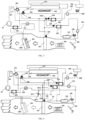
- a thermal management system includes a refrigerant system and a coolant system.
- a refrigerant of the refrigerant system and a coolant of the coolant system are isolated from each other without contacting each other.
- the refrigerant system includes a compressor 10, a first heat exchanger 101 and a throttling element.
- the throttling element includes a first throttling device 204 and a second throttling device 208.
- An outlet of the compressor 10 is in communication with a refrigerant inlet of the first heat exchanger 101.
- the thermal management system also includes a first dual-channel heat exchanger 104.
- the first dual-channel heat exchanger 104 has a refrigerant flow channel and a coolant flow channel.
- the refrigerant flowing through the refrigerant flow channel and the coolant flowing through the coolant flow channel can exchange heat in the first dual-channel heat exchanger 104.
- An inlet of the refrigerant flow channel of the first dual-channel heat exchanger 104 is in communication with the first throttling device 204.
- An outlet of the refrigerant flow channel of the first dual-channel heat exchanger 104 is in communication with an inlet of the compressor 10 or is in communication with the inlet of the compressor 10 via a gas-liquid separator 207.
- the thermal management system also includes a second dual-channel heat exchanger 109.
- the second dual-channel heat exchanger 109 has a refrigerant flow channel and a coolant flow channel.
- the refrigerant flowing through the refrigerant flow channel and the coolant flowing through the coolant flow channel can exchange heat in the second dual-channel heat exchanger 109.
- An inlet of the refrigerant flow channel of the second dual-channel heat exchanger 109 is in communication with the second throttling device 208.
- An outlet of the refrigerant flow channel of the second dual-channel heat exchanger 109 is in communication with the inlet of the compressor 10 or is in communication with the inlet of the compressor 10 via the gas-liquid separator 207.
- the coolant system includes a first loop and a second loop. The first loop and the second loop can operate independently from each other.
- the first loop includes the coolant flow channel of the first dual-channel heat exchanger 104, a second heat exchanger 106 and a first pump 502.
- the coolant flow channel of the first dual-channel heat exchanger 104, the second heat exchanger 106 and the first pump 502 are in communication in series so as to form the first loop.
- the first pump 502 can drive the coolant to flow in the first loop.
- the second heat exchanger 106 can be used to adjust the temperature of heat-generating devices such as motors, inverters and controllers.
- the heat-generating device such as the motor can directly or indirectly exchange heat with the coolant in the second heat exchanger 106, thereby adjusting the temperature of the heat-generating device such as the motor.
- the second loop includes the coolant flow channel of the second dual-channel heat exchanger 109, a third heat exchanger 105 and a second pump 501.
- the coolant flow channel of the second dual-channel heat exchanger 109, the third heat exchanger 105 and the second pump 501 are in communication in series so as to form the second loop.
- the second pump 501 can drive the coolant to flow in the second loop.
- the third heat exchanger 105 can be used to adjust the temperature of a heat-generating device such as a battery.
- the heat-generating device such as the battery can directly or indirectly exchange heat with the coolant in the third heat exchanger 105, thereby adjusting the temperature of the heat-generating device such as the battery. Since the working temperature of heat-generating device such as the motor is higher than that of heat-generating device such as the battery, the coolant in the first loop is not in communication with the coolant in the second loop in order to prevent damage to the battery.
- the first loop includes a first branch.
- the first branch includes the second heat exchanger 106 and the first pump 502.
- the second heat exchanger 106 is in communication with the first pump 502.
- the first branch has two ports.
- the two ports of the first branch are an inlet of the coolant flowing into the first branch and an outlet of the coolant flowing out of the first branch.
- the two ports of the first branch can be openings of a device or openings of a pipeline.
- the first pump 502 and/or the second pump 501 are also referred to as a pump 50.
- the second loop includes a second branch.
- the second branch includes the third heat exchanger 105 and the second pump 501.
- the second branch has two ports.
- the two ports of the second branch are an inlet of the coolant flowing into the second branch and an outlet of the coolant flowing out of the second branch.
- the two ports of the second branch can be openings of a device or openings of a pipeline.
- the two ports of the second branch are communicated with the two ports of the coolant flow channel of the second dual-channel heat exchanger 109, respectively.
- the coolant system also includes a fourth heat exchanger 107.
- the fourth heat exchanger 107 is disposed in the first loop.
- the fourth heat exchanger 107 is a part of the first loop.
- the fourth heat exchanger 107 may be an air-cooled heat exchanger, such as a microchannel heat exchanger.
- the fourth heat exchanger 107, the first pump 502 and the second heat exchanger 106 are in communication in series.
- the fourth heat exchanger 107 is disposed outside an air-conditioning box of a vehicle, and the fourth heat exchanger 107 can exchange heat with the environment air.
- the coolant in the first loop only circulates in the first loop.
- the heat of heat-generating device such as the motor is released into the air through the fourth heat exchanger 107.
- the fourth heat exchanger 107 can be disposed in the second loop, which will not be described in detail.
- the first loop and the second loop may also share the fourth heat exchanger 107.
- the second loop When the second loop needs to dissipate heat, the second loop is in communication with the fourth heat exchanger 107.
- the coolant system may also include two fourth heat exchangers 107, one of which is disposed in the first loop, and the other of which is disposed in the second loop.
- the refrigerant system includes a first throttling unit 205, a seventh heat exchanger 103 and a first valve device 201.
- the seventh heat exchanger 103 includes at least a first port and a second port.
- the first throttling unit 205 can be in communication with the second port of the seventh heat exchanger 103.
- the refrigerant inlet of the first heat exchanger 101 is in communication with the outlet of the compressor 10.
- the refrigerant outlet of the first heat exchanger 101 is in communication with the first valve device 201.
- the refrigerant outlet of the first heat exchanger 101 can be in communication with the first throttling unit 205 through the first valve device 201.
- the first heat exchanger 101 can also be communication with the first throttling device 204 and/or the second throttling device 208 through the first valve device 201.
- the first port of the seventh heat exchanger 103 can also be communication with the inlet of the compressor 10 through the first valve device 201, or be communication with the inlet of the compressor 10 through the first valve device 201 and the gas-liquid separator 207 which is communicated between the first valve device 201 and the compressor 10.
- the refrigerant system also includes an eighth heat exchanger 102 and a second throttling unit 202.
- the second throttling unit 202 can be in communication with an inlet of the eighth heat exchanger 102.
- the eighth heat exchanger 102 is in communication with the inlet of the compressor 10 or is in communication with the inlet of the compressor 10 via the gas-liquid separator 207.
- the first valve device 201 includes a first communication port, a second communication port, a third communication port and a fourth communication port. Specifically, the first communication port is in communication with the refrigerant outlet of the first heat exchanger 101.
- the fourth communication port is in communication with the inlet of the compressor 10.
- the second communication port can be in communication with at least one of the first throttling unit 205, the first throttling device 204, the second throttling device 208 and the second throttling unit 202.
- the third communication port is in communication with the first port of the seventh heat exchanger 103.
- the first valve device 201 includes a first working state and a second working state. In the first working state of the first valve device 201, the first valve device 201 only opens the communication channel between the first communication port and the third communication port, and closes the communication channels of other communication ports. In the second working state of the first valve device 201, the first valve device 201 opens the communication channel between the first communication port and the second communication port, and opens the communication channel between the third communication port and the fourth communication port.
- the first heat exchanger 101 and the eighth heat exchanger 102 are disposed in the air-conditioning box of the vehicle, and are used to adjust the temperature of a passenger compartment of the vehicle.
- the seventh heat exchanger 103 and the fourth heat exchanger 107 are disposed outside the air-conditioning box of the vehicle, and can exchange heat with the environment air.
- the second port of the seventh heat exchanger 103 is also provided with a one-way element 206 parallel to the first throttling unit 205.
- the second communication port can be in communication with the second port of the seventh heat exchanger 103 through the first throttling unit 205 and the one-way element 206 which are connected in parallel.
- the one-way element 206 is turned on when the refrigerant flows out of the second port of the seventh heat exchanger 103, and is turned off when the refrigerant flows toward the second port of the seventh heat exchanger 103.
- the inlet of the one-way element 206 is in communication with the second port of the seventh heat exchanger 103.
- first throttling unit 205 can also use a throttling device with a cut-off function, so that the one-way element 206 can be eliminated.
- connection or communication described in this specification can be direct connection or communication.
- two components can also be assembled together, which eliminates the need of a connecting pipeline, and the system is more compact.
- the connection or communication may also be an indirect connection or communication, such as communication through a pipeline, or communication after passing through a certain component, which will not be illustrated one by one here.
- turning on the throttling device means that the opening degree of the throttling device is the largest
- turning off the throttling device means that the opening degree of the throttling device is zero
- opening the throttling device refers to a state between turning on and turning off, or a throttling state of the throttling device.
- the second throttling device 208 and the first throttling device 204 may be throttling devices such as a thermal expansion valve, an electronic expansion valve, or a capillary tube that can regulate the refrigerant flowing therethrough.
- the one-way element 206 can be a shut-off valve with on-off control function, a flow regulating valve or a solenoid valve, or a one-way valve that flows in one direction and shuts off in the other direction.
- the one-way element or valve module can also be integrated with the heat exchanger to form an assembly with a more compact structure, such as an assembly formed by the integration of the second throttling unit 202 and the eighth heat exchanger 102.
- the coolant system of the thermal management system further includes a coolant storage device 108.
- the medium in the coolant storage device 108 may be a coolant.
- the coolant flow channel of the second dual-channel heat exchanger 109, the coolant storage device 108, the second pump 501 and the third heat exchanger 105 are in communication in series. At this time, the coolant in the coolant storage device 108 participates in the flow of the coolant system in the second loop.
- the coolant storage device 108 may also only be in communication with the second loop and participate in the flow of the coolant in the second loop.
- a coolant storage device 108' may also be provided in the first loop, which will not be described in detail.
- the air-conditioning box of the vehicle is provided with several air ducts (not shown) to communicate with the passenger compartment of the vehicle.
- a grille (not shown) is provided in the air duct in order to adjust the size of the air duct.
- An inner circulation air opening, an outer circulation air opening, a circulation damper 301 for adjusting the size of the inner circulation air opening and the outer circulation air opening, and a motor for driving the circulation damper 301 are disposed on a side of the air-conditioning box where the air enters.
- the inner circulation air opening is communicated with the passenger compartment of the vehicle.
- the air in the passenger compartment of the vehicle enters the air-conditioning box through the inner circulation air opening and then re-enters the vehicle cabin through the air duct, forming an inner circulation.
- the outer circulation air opening is communicated with the outside of the passenger compartment of the vehicle.
- the air outside the vehicle enters the air-conditioning box through the outer circulation air opening, and enters the passenger compartment of the vehicle through the air duct.
- the circulation damper 301 is disposed between the inner circulation port and the outer circulation port.
- the controller can control the circulation damper 301 through the motor.
- the circulation damper 301 is switched to the inner circulation port, the inner circulation port can be closed to form an outer circulation.
- the circulation damper 301 is switched to the outer circulation port, the outer circulation port can be closed to form the inner circulation.
- a fan 303 is also provided on one side of the seventh heat exchanger 103, which can accelerate the air speed flowing through the seventh heat exchanger 103.
- the first heat exchanger 101 is disposed in the air-conditioning box.
- a blower 304 is provided at a position of the air-conditioning box close to the inner circulation air opening and the outer circulation air opening.
- a temperature damper 302 is also provided on an upwind side of the first heat exchanger 101.
- the thermal management system further includes the eighth heat exchanger 102
- the first heat exchanger 101 and the eighth heat exchanger 102 may be disposed in the air-conditioning box at a certain distance.
- the temperature damper 302 is disposed between the first heat exchanger 101 and the eighth heat exchanger 102.
- the seventh heat exchanger 103 and the fourth heat exchanger 107 are disposed outside the air-conditioning box of the vehicle. Specifically, the seventh heat exchanger 103 and the fourth heat exchanger 107 are disposed at a front end module of the vehicle close to a front bumper.
- the thermal management system includes a heating mode and a first cooling mode.
- the working conditions of the thermal management system under several modes are described below.
- the heating mode of the thermal management system includes a first heating mode and a second heating mode.
- the thermal management system executes the first heating mode.
- the first valve device 201 is in the second working state, and the first throttling unit 205 and the first throttling device 204 are opened.
- the refrigerant of the thermal management system is compressed by the compressor 10 and becomes a high-temperature and high-pressure refrigerant.
- the temperature damper 302 is opened.
- the high-temperature and high-pressure refrigerant exchanges heat with the surrounding air in the first heat exchanger 101.
- the refrigerant in the first heat exchanger 101 releases heat to the surrounding air.
- the flow paths for the refrigerant outlet of the first heat exchanger 101 leading to the second port of the seventh heat exchanger 103, and leading to the refrigerant flow channels of the first dual-channel heat exchanger 104 and the second dual-channel heat exchanger 109 are turned on, and the flow path leading to the eighth heat exchanger 102 is closed.
- the refrigerant enters the seventh heat exchanger 103 after being throttled by the first throttling unit 205.
- the low-temperature and low-pressure refrigerant exchanges heat with the surrounding air in the seventh heat exchanger 103 and absorbs the heat of the air.
- the refrigerant can return to the compressor 10 after flowing out of the seventh heat exchanger 103, the refrigerant enters the compressor 10, and is compressed again by the compressor 10 into a high-temperature and high-pressure refrigerant, which works in cycles in this way.
- the refrigerant flowing through the refrigerant flow channels of the first dual-channel heat exchanger 104 exchanges heat with the coolant of the coolant system, then the refrigerant enters the compressor 10 and is compressed by the compressor 10 again.
- the situation of the second dual-channel heat exchanger 109 is the same as the situation of the first dual-channel heat exchanger 104, which will not be described in detail.
- both the first throttling device 204 and the second throttling device 208 are opened, and both the first dual-channel heat exchanger 104 and the second dual-channel heat exchanger 109 participate in the work.
- only one of the first throttling device 204 and the second throttling device 208 may be opened.
- the first throttling device 204 may be a thermal expansion valve with a cut-off function, which can reduce the cost.
- the second throttling device 208 can be an electronic expansion valve, which can accurately control the temperature of device such as the battery.
- the heat-generating device such as the motor exchanges heat with the second heat exchanger 106
- the coolant in the second heat exchanger 106 absorbs heat from the heat-generating device such as the motor.
- the thermal management system obtains the heat absorbed by the second heat exchanger 106 from the heat-generating device such as the motor through the first dual-channel heat exchanger 104, and releases it to the air-conditioning box through the first heat exchanger 101.
- there are two heat sources for the thermal management system which are the air outside the air-conditioning box of the vehicle and the heat-generating device such as the motor.
- the fourth heat exchanger 107 can absorb heat from the environment air.
- the fourth heat exchanger 107 is disposed upstream of the second heat exchanger 106.
- the word "upstream” mentioned here means that the coolant firstly passes through the fourth heat exchanger 107 and then passes through the second heat exchanger 106. This setting is because the temperature of the environment air is lower than the temperature of the heat-generating device such as the motor, the coolant firstly absorbs the heat of the environment air in the fourth heat exchanger 107, the temperature of the coolant rises, then the second heat exchanger 106 absorbs the heat, and then the temperature of the coolant can be further increased.
- the thermal management system can absorb heat from the air through the fourth heat exchanger 107, which is equivalent to increasing the heat exchange area of the seventh heat exchanger 103. Because the specific heat capacity of the coolant is larger than that of the air, and the temperature change range is smaller, the superheat control of the first dual-channel heat exchanger 104 is relatively easier than the control of the seventh heat exchanger 103. In addition, the dual-channel heat exchanger has a small volume, a short flow channel, and better oil return.
- the temperature outside the vehicle In winter, the temperature outside the vehicle is low in some areas. When the outside temperature is lower than or close to zero and the humidity is high to reach the dew point temperature, the surface of the seventh heat exchanger 103 is easy to frost, freeze, or malfunction, which will affect the energy efficiency of the thermal management system and even lose the heating performance.
- the thermal management system executes the second heating mode, the first valve device 201 is in the second working state, and at least one of the first throttling device 204 and the second throttling device 208 is opened.
- the refrigerant flowing out of the first heat exchanger 101 enters the first throttling device 204 and/or the second throttling device 208, after passing through the first valve device 201.
- the second throttling unit 202 is turned off.
- the thermal management system absorbs heat from the air and the heat-generating device such as the motor through the first loop; and/or, the thermal management system absorbs heat from the air and the heat-generating device such as the battery through the second loop.
- the refrigerant flowing through the first dual-channel heat exchanger 104 can absorb heat from the coolant in the first loop; or the refrigerant flowing through the second dual-channel heat exchanger 109 can absorb heat from the second loop.
- the seventh heat exchanger 103 cannot effectively absorb heat, the heat of the device such as the battery or the device such as the motor is used to provide a certain amount of heat indoors, which is beneficial to improve comfort.
- the thermal management system absorbs heat through the seventh heat exchanger 103, and then releases heat in the first heat exchanger 101, which will not be described in detail.
- the compressor 10 is turned off.
- the first pump 502 is turned on to allow the coolant in the first loop to flow in the first loop.
- the heat of the heat-generating device such as the motor is released to the coolant, and finally released into the air through the fourth heat exchanger 107.
- the heat-generating device such as the motor can be cooled by the first dual-channel heat exchanger 104, or the heat-generating device such as the motor can be cooled by itself, or the heat can be dissipated by another fourth heat exchanger 107.
- the first pump 502 In the first cooling mode, the first pump 502 is turned on, the fourth heat exchanger 107, the first pump 502 and the second heat exchanger 106 are in communication, and the first pump 502 drives the coolant to flow in the first loop.
- the first cooling mode at least one of the battery or the motor uses the fourth heat exchanger 107 to release heat.
- the compressor 10 may not be turned on or the compressor 10 may be operated with relatively low power consumption, which can reduce energy consumption and save energy.
- the thermal management system in the heating mode of the thermal management system, the thermal management system can absorb heat in the air through the fourth heat exchanger 107. In the first cooling mode of the thermal management system, the thermal management system can release heat to the air through the fourth heat exchanger 107.
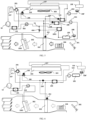
- the refrigerant system can also be provided with only one throttling device 204', that is, only one of the first throttling device 204 and the second throttling device 208 in the first embodiment is provided.
- the refrigerant system includes a first valve 2003.
- the first valve 2003 is a three-way valve.
- the first valve 2003 has three connection ports.
- a first connection port of the first valve 2003 can be in communication with a second connection port of the first valve 2003 and/or a third connection port of the first valve 2003.
- the first valve 2003 may be a three-way switching valve or a three-way flow regulating valve.
- the first connection port of the first valve 2003 is in communication with a first port of the throttling device 204'.
- a second port of the throttling device 204' is in communication with the outlet of the one-way element 206.
- the second connection port of the first valve 2003 is in communication with the refrigerant inlet of the first dual-channel heat exchanger 104.
- the third connection port of the first valve 2003 is in communication with the inlet of the refrigerant flow channel of the second dual-channel heat exchanger 109.
- the first dual-channel heat exchanger 104 does not work, and the refrigerant exchanges heat with the coolant of the second loop in the second dual-channel heat exchanger 109.
- the second pump 501 is turned off and the first pump 502 is turned on.
- the refrigerant and the coolant of the first loop exchange heat in the first dual-channel heat exchanger 104, and the second dual-channel heat exchanger 109 does not work.
- the first valve 2003 may also be a combination of two shut-off valves or flow regulating valves, which will not be described in detail.
- the thermal management system can save an expansion valve and relatively reduce the cost.
- the first throttling device 204 and the second throttling device 208 are thermal expansion valves or capillary tubes, in order to facilitate the control of the working conditions of the first dual-channel heat exchanger 104 and the second dual-channel heat exchanger 109, the refrigerant system is also provided with the first valve 2003. As shown in FIG.
- the first connection port of the first valve 2003 is in communication with the outlet of the one-way element 206
- the second connection port of the first valve 2003 is in communication with the refrigerant inlet of the first dual-channel heat exchanger 104 through the first throttling device 204
- the third connection port of the first valve 2003 is in communication with the refrigerant inlet of the second dual-channel heat exchanger 109 through the second throttling device 208.
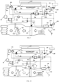
- the first heat exchanger 101 is a dual-channel heat exchanger.
- the first heat exchanger 101 may be a plate heat exchanger.
- the first heat exchanger 101 includes a refrigerant flow channel and a coolant flow channel.
- the outlet of the compressor 10 is in communication with an inlet of the refrigerant flow channel of the first heat exchanger 101.
- the high-temperature and high-pressure refrigerant can release heat in the refrigerant flow channel of the first heat exchanger 101 to increase the heat of the coolant in the coolant flow channel.
- the thermal management system includes a third loop.
- the third loop includes a third pump 503, the coolant flow channel of the first heat exchanger 101 and a sixth heat exchanger 1001.
- the third pump 503, the coolant flow channel of the first heat exchanger 101 and the sixth heat exchanger 1001 are in communication in series.
- the sixth heat exchanger 1001 is disposed in an air-conditioning box of a vehicle, and the first heat exchanger 101 is disposed outside the air-conditioning box of the vehicle.
- the third loop can exchange heat with the second loop or the first loop.
- the thermal management system further includes a first communication pipeline 51 and a second communication pipeline 52.
- Each of the first communication pipeline 51 and the second communication pipeline 52 includes a first end and a second end.
- the first end of the first communication pipeline 51 is in communication with the second loop.
- the second end of the first communication pipeline 51 is in communication with the third loop.
- the first end of the second communication pipeline 52 is in communication with the second loop.
- the second end of the second communication pipeline 52 is in communication with the third loop.
- the thermal management system can realize the exchange of the coolant of the second loop and the coolant of the third loop through the first communication pipeline 51 and the second communication pipeline 52, or the coolant in the second loop can flow into the third loop through the first communication pipeline 51 or the second communication pipeline 52.
- the coolant in the third loop can flow into the second loop through the first communication pipeline 51 or the second communication pipeline, and finally realize the heat exchange between the second loop and the third loop.
- at least one port is directly or indirectly communicated with the inlet of the third pump 503 or the second pump 501.
- the second end of the first communication pipeline 51 is communicated with the inlet of the third pump 503.
- the second end of the first communication pipeline 51 is communicated with the second loop. Both ends of the second communication pipeline 52 are communicated with the second loop and the third loop. However, both ends of the second communication pipeline are not directly communicated with the third pump 503 or the second pump 501. This facilitates the flow of coolant in the second loop and the third loop to each other.
- the third loop includes a third branch.
- the third branch includes a third pump 503, the coolant flow channel of the first heat exchanger 101 and a sixth heat exchanger 1001 communicated in series.
- the third branch is a discommunicated form of the third loop.
- the coolant system includes a third valve member 401.
- the third valve member 401 includes a first connecting port 4011, a second connecting port 4012 and a third connecting port 4013.
- the third valve member 401 can open or close a communication path between the first connecting port 4011 and the third connecting port 4013 or a communication path between the first connecting port 4011 and the second connecting port 4012.
- the first connecting port 4011 of the third valve member 401 and the second connecting port 4012 of the third valve member 401 are in communication with both ends of the third branch.
- the third connecting port 4013 of the third valve member 401 is in communication with one end of the second communication pipeline 52.
- the other end of the second communication pipeline 52 is in communication with one end of the second branch.
- Two ends of the first communication pipeline 51 communicate with the corresponding other ends of the second branch and the third branch.
- the thermal management system can control whether the second loop and the third loop perform coolant exchange through the third valve member 401.
- the coolant in the third loop flows in the third loop.
- a circulation mode of the thermal management system that is, when the third loop and the second loop need heat exchange, for example, when using the heat generated by the first heat exchanger 101 to increase the heat of the battery and other heat-generating device, or using the heat of the battery and other heat-generating device to heat the passenger compartment
- the first connecting port 4011 and the second connecting port 4012 of the third valve member 401 are controlled not to be communicated
- the first connecting port 4011 of the third valve member 401 is controlled to be communicated with the third connecting port 4013
- the second loop and the third loop exchange the coolant, and finally realize the heat exchange between the second loop and the third loop.
- the heat of the second loop is released in the third loop through the first communication pipeline 51 and the second communication pipeline 52 so as to increase the temperature of the passenger compartment.
- the heat of the third loop is released in the second loop through the first communication pipeline 51 and the second communication pipeline 52 so as to increase the temperature of the device such as the battery.
- the third valve member 401 may only include two connecting ports, for example, the third valve member 401 includes a first connecting port and a second connecting port.
- the third valve member 401 can open or close a communication path between the first connecting port of the third valve member 401 and the second connecting port of the third valve member 401.
- the first connecting port of the third valve member 401 is in communication with the first communication pipeline 51.
- the second connecting port of the third valve member 401 is in communication with one end of the second branch or one end of the third branch.
- the second loop is controlled by the thermal management system to communicate with the third loop through the third valve member 401.
- the third valve member 401 may also be communicated with the second communication pipeline 52, which will not be described in detail.
- the coolant system may also include a fourth valve member.
- the communication mode of the fourth valve member is the same as the communication mode of the third valve member, which will not be described in detail.
- the coolant system includes a third dual-channel heat exchanger 2001.
- the third dual-channel heat exchanger 2001 defines a first flow channel and a second flow channel.
- the first flow channel of the third dual-channel heat exchanger 2001 is a part of the third loop.
- the second flow channel of the third dual-channel heat exchanger 2001 is a part of the second loop.
- the coolant of the second loop and the coolant of the third loop can exchange heat in the third dual-channel heat exchanger 2001.
- the second loop and the third loop only exchange heat and do not exchange coolant.
- the thermal management system can control whether the second loop and the third loop exchange heat by controlling the third pump 503 and the second pump 501.
- the coolant system further includes a bypass pipeline 53 and a fifth valve member 404.
- the bypass pipeline 53 and the fifth valve member 404 are disposed in the third loop.
- the bypass pipeline 53 is disposed in parallel with the first flow channel of the third dual-channel heat exchanger 2001. By controlling the fifth valve member 404, the bypass pipeline 53 bypasses the first flow channel of the third dual-channel heat exchanger 2001.
- bypass pipeline 53 and the fifth valve member 404 can also be disposed in the second loop.
- the bypass pipeline 53 can bypass the second flow channel of the third dual-channel heat exchanger 2001, which will not be described in detail.
- the second loop and the third loop of the thermal management system can operate independently and simultaneously when the second loop and the third loop do not exchange heat, which is convenient for control.
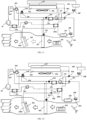
- the thermal management system includes the first dual-channel heat exchanger 104, but does not include the second dual-channel heat exchanger 109.
- the third heat exchanger 105 is disposed in the first loop.
- the first loop includes the third heat exchanger 105.
- the second heat exchanger 106 and the third heat exchanger 105 are in communication in series.
- the second heat exchanger 106 and the third heat exchanger 105 may also be communicated in series with the first pump 502 after being communicated in parallel.
- the second heat exchanger 106 and the third heat exchanger 105 are in communication in series or in parallel, then communicated with the coolant flow channel of the first dual-channel heat exchanger 104 in parallel, and then communicated with the first pump 502 and the fourth heat exchanger in series.
- the second heat exchanger and the third heat exchanger are disposed in the same loop, so that the thermal management system has the advantage of being relatively simple.
- the fourth heat exchanger 107 is disposed in the first branch.
- the fourth heat exchanger 107 can also be disposed in the second branch, or both the first branch and the second branch are provided with the fourth heat exchanger 107.
- the coolant system includes a second valve member 402.
- the second valve member 402 is a three-way valve.
- a first mating port 4021 of the second valve member 402 can be in communication with a second mating port 4022 of the second valve member 402 or a third mating port 4023 of the second valve member 402.
- the first mating port 4021 of the second valve member 402 can be in communication with a port of the second branch.
- the second mating port 4022 of the second valve member 402 can be in communication with one port of the coolant flow channel of the first dual-channel heat exchanger 104.
- the other port of the second branch and the other port of the coolant flow channel of the first dual-channel heat exchanger 104 can be in communication with the third mating port 4023 of the second valve member 402.
- the coolant flow channel of the first dual-channel heat exchanger 104 is in communication with the first branch. That is, the coolant flow channel of the first dual-channel heat exchanger 104, the second pump 501 and the third heat exchanger 105 are in communication in series.
- the second valve member 402 may also be a combination of two shut-off valves or flow regulating valves, which will not be described in detail.
- the coolant flow channel of the first dual-channel heat exchanger 104 can be communicated with the first branch or the second branch.
- the coolant flow channel of the first dual-channel heat exchanger 104 can be communicated with the first branch or the second branch
- the coolant flow channel of the first dual-channel heat exchanger 104 can be communicated with the first branch or the second branch.
- the coolant of the first branch or the second branch can flow into and out of the coolant flow channel of the first dual-channel heat exchanger 104.
- the coolant system includes a first valve member 403.
- the first valve member 403 is a three-way valve.
- the first valve member 403 has three connection ports.
- a first connection port 4031 of the first valve member 403 can be in communication with a second connection port 4032 of the first valve member 403 or a third connection port 4033 of the first valve member 403.
- the first connection port 4031 of the first valve member 403 is in communication with one port of the first branch.
- the second connection port 4032 of the first valve member 403 is in communication with one port of the coolant flow channel of the first dual-channel heat exchanger 104.
- the third connection port 4033 of the first valve member 403 and the other port of the coolant flow channel of the first dual-channel heat exchanger 104 can be in communication with the other port of the first branch.
- the first connection port 4031 of the first valve member 403 is in communication with the third connection port 4033, and the first connection port 4031 of the first valve member 403 is not communicated with the second connection port 4032, the first valve member 403 and the first branch form a first loop, and the coolant flow channel of the first dual-channel heat exchanger 104 is not communicated with the first loop.
- the coolant flow channel of the first heat exchanger 104 is in communication with the first branch. That is, the coolant flow channel of the first dual-channel heat exchanger 104, the first pump 502, and the second heat exchanger 106 are in communication in series. At this time, the heat of the coolant in the first branch can be released to the refrigerant system through the first dual-channel heat exchanger 104.
- the first valve member 403 may also be a combination of two shut-off valves or flow regulating valves, which will not be described in detail.
- the coolant flow channel of the first dual-channel heat exchanger 104 can be communicated with the first loop, or the coolant flow channel of the first dual-channel heat exchanger 104 is communicated with the second loop.
- the heat-generating device such as the motor exchanges heat with the second heat exchanger 106
- the coolant in the second heat exchanger 106 absorbs the heat of the heat-generating device such as the motor.
- the refrigerant flowing through the first dual-channel heat exchanger 104 obtains the heat absorbed by the second heat exchanger 106 from heat-generating device such as the motor through the first dual-channel heat exchanger 104, and is released to the air-conditioning box through the eighth heat exchanger 102.
- there are two heat sources for the thermal management system which are the air outside the air-conditioning box of the vehicle and the heat-generating device such as the motor.
- the fourth heat exchanger 107 is also disposed in the first loop, the fourth heat exchanger 107 can absorb heat from the environment air, which is equivalent to increasing the heat exchange area of the seventh heat exchanger. As a result, it is beneficial to improve the heat exchange performance.
- the heat absorbed by the second heat exchanger 106 from the heat-generating device such as the motor can also be released through the fourth heat exchanger 107 to reduce the temperature of the heat-generating device such as the motor.
- the refrigerant suitable for the refrigerant system can be a conventional refrigerant, such as R134a, or a refrigerant with a supercritical state, such as CO 2 .
- the eighth heat exchanger 102 may be a dual-channel heat exchanger. At this time, the eighth heat exchanger 102 is disposed outside the air-conditioning box. In this way, the refrigerant system is all disposed outside the air-conditioning box, which is helpful to prevent the health of passengers from being harmed when CO 2 escapes. Due to the high working pressure of CO 2 , the refrigerant system components working under high pressure are located outside the air-conditioning box, which is also helpful to prevent damage to passengers due to accidental explosion of the components.
- the refrigerant system includes a compressor 10 and a first throttling device 204.
- the first dual-channel heat exchanger 104 of the thermal management system has a refrigerant flow channel and a coolant flow channel.
- the refrigerant flowing through the refrigerant flow channel and the coolant flowing through the coolant flow channel can exchange heat in the first dual-channel heat exchanger 104.
- An inlet of the refrigerant flow channel of the first dual-channel heat exchanger 104 is in communication with the first throttling device 204.
- An outlet of the refrigerant flow channel of the first dual-channel heat exchanger 104 is in communication with the inlet of the compressor 10 or is in communication with the inlet of the compressor 10 via a gas-liquid separator 207.
- the coolant system includes a first loop and a second loop. The first loop and the second loop can operate independently of each other.
- the first loop includes a second heat exchanger 106 and a first pump 502.
- the second heat exchanger 106 and the first pump 502 are in communication in series so as to form a first loop.
- the first pump 502 can drive the coolant to flow in the first loop.
- the second heat exchanger 106 can be used to adjust the temperature of a heat-generating device such as a motor.
- the heat-generating device such as the motor can directly or indirectly exchange heat with the coolant in the second heat exchanger 106, thereby adjusting the temperature of the heat-generating device such as the motor.
- the second loop includes a third heat exchanger 105 and a second pump 501.
- the third heat exchanger 105 and the second pump 501 are in communication in series so as to form a second loop.
- the second pump 501 can drive the coolant to flow in the second loop.
- the third heat exchanger 105 can be used to adjust the temperature of a heat-generating device such as a battery.
- the heat-generating device such as the battery can directly or indirectly exchange heat with the coolant in the third heat exchanger 105, thereby adjusting the temperature of the heat-generating device such as the battery.
- the first loop includes a first branch.
- the first branch includes the second heat exchanger 106 and the first pump 502.
- the second heat exchanger 106 is in communication with the first pump 502.
- the first branch has two ports.
- the two ports of the first branch are an inlet of the first branch and an outlet of the first branch, respectively.
- the two ports of the first branch can be openings of a device or openings of a pipeline.
- the coolant system includes a first valve member 403.
- the first valve member 403 is a three-way valve.
- the first valve member 403 has three connection ports.
- a first connection port 4031 of the first valve member 403 can be in communication with a second connection port 4032 of the first valve member 403 or a third connection port 4033 of the first valve member 403.
- the first connection port 4031 of the first valve member 403 is in communication with one port of the first branch.
- the second connection port 4032 of the first valve member 403 is in communication with one port of the coolant flow channel of the first dual-channel heat exchanger 104.
- the third connection port 4033 of the first valve member 403 and the other port of the coolant flow channel of the first dual-channel heat exchanger 104 can be in communication with the other port of the first branch.
- the first valve member 403 and the first branch form a first loop, and the coolant flow channel of the first dual-channel heat exchanger 104 is not communicated with the first loop.
- the coolant flow channel of the first dual-channel heat exchanger 104 is in communication with the first branch.
- the coolant flow channel of the first dual-channel heat exchanger 104, the first pump 502, and the second heat exchanger 106 are in communication in series. At this time, the heat of the coolant in the first branch can be released to the refrigerant system through the first dual-channel heat exchanger 104.
- the first valve member 403 may also be a combination of two shut-off valves or flow regulating valves, which will not be described in detail.
- the second loop includes a second branch.
- the second branch includes a third heat exchanger 105 and a second pump 501.
- the second branch has two ports.
- the two ports of the second branch are an inlet of the coolant into the second branch and an outlet of the second branch, respectively.
- the two ports of the second branch can be openings of a device or openings of a pipeline.
- the coolant system includes a second valve member 402.
- the second valve member 402 is a three-way valve.
- a first mating port 4021 of the second valve member 402 can be in communication with a second mating port 4022 of the second valve member 402 or a third mating port 4023 of the second valve member 402.
- the first mating port 4021 of the second valve member 402 can be in communication with one port of the second branch.
- the second mating port 4022 of the second valve member 402 can be in communication with one port of the coolant flow channel of the first dual-channel heat exchanger 104.
- the other port of the second branch and the other port of the coolant flow channel of the first dual-channel heat exchanger 104 can be in communication with the third mating port 4023 of the second valve member 402.
- the second valve member 402 and the second branch form a second loop, and the coolant flow channel of the first dual-channel heat exchanger 104 is not communicated with the second loop.
- the coolant flow channel of the first dual-channel heat exchanger 104 is in communication with the first branch.
- the coolant flow channel of the first dual-channel heat exchanger 104, the second pump 501 and the third heat exchanger 105 are in communication in series.
- the second valve member 402 may also be a combination of two shut-off valves or flow regulating valves, which will not be described in detail.
- the coolant system also includes a fourth heat exchanger 107.
- the fourth heat exchanger 107 is disposed in the first branch.
- the fourth heat exchanger 107 is a part of the first branch.
- the fourth heat exchanger 107 may be an air-cooled heat exchanger, such as a microchannel heat exchanger.
- the fourth heat exchanger 107, the first pump 502 and the second heat exchanger 106 are in communication in series.
- the fourth heat exchanger 107 is disposed outside the air-conditioning box of the vehicle, and the fourth heat exchanger 107 can exchange heat with the environment air.
- the coolant in the first loop only circulates in the first loop, and the heat of the heat-generating device such as the motor is released into the air through the fourth heat exchanger 107.
- the fourth heat exchanger 107 may also be disposed in parallel with the second heat exchanger 106 and then communicate with the first pump 502 in series.
- the fourth heat exchanger 107 is in serial communication with the first pump 502, the second heat exchanger 106 and the first pump 502 are also communicated in series, and the second heat exchanger 106 and the fourth heat exchanger 107 are disposed in parallel.
- the fourth heat exchanger 107 may be disposed in the second branch.
- the coolant system may also include two fourth heat exchangers 107, one of which is disposed in the first branch, and the other of which is disposed in the second branch. In the direction of gravity, the height of the two ports of the first branch is higher than that of the coolant flow channel of the first heat exchanger 101. The height of the two ports of the second branch is higher than the coolant flow channel of the first heat exchanger 101. As a result, it can reduce the flow of the higher-temperature coolant to the lower-temperature coolant, reduce heat exchange and reduce heat loss.
- the first heat exchanger 101 is a dual-channel heat exchanger.
- the first heat exchanger 101 includes a refrigerant flow channel and a coolant flow channel.
- the refrigerant flow channel of the first heat exchanger 101 exchanges heat with the coolant flow channel.
- the coolant system further includes a third loop which can exchange heat with the second loop or the first loop.
- the third loop includes a third branch.
- the third branch includes a third pump 503, the coolant flow channel of the first heat exchanger 101 and a sixth heat exchanger 1001 communicated in series.
- the coolant system includes a third valve member 401.
- the thermal management system can control whether the second loop and the third loop perform coolant exchange through the third valve member 401.
- the third valve member is controlled to exchange the coolant in the second loop and the third loop, and finally the heat exchange between the second loop and the third loop is realized.
- the heat of the second loop is released in the third loop so as to increase the temperature of the passenger compartment.
- the first heat exchanger 101 is disposed outside the air-conditioning box.
- the sixth heat exchanger 1001 is in communication with the coolant flow channel of the first heat exchanger 101.
- the sixth heat exchanger 1001 is disposed in the air-conditioning box, so that the sixth heat exchanger 1001 can adjust the temperature in the passenger compartment of the vehicle.
- the seventh heat exchanger 103 and the fourth heat exchanger 107 are disposed outside the air-conditioning box of the vehicle. Specifically, the seventh heat exchanger 103 and the fourth heat exchanger 107 are provided in a front-end module of the vehicle.
- the coolant system can also be provided with only one pump 50.
- An outlet of the pump 50 is in communication with a port of the coolant flow channel of the first dual-channel heat exchanger 104.
- the second connection port 4032 of the first valve member 403 is in communication with the coolant flow channel of the first dual-channel heat exchanger 104 through the outlet of the pump 50.
- the thermal management system can save one pump and relatively reduce the cost.
- the first heat exchanger 101 is a dual-channel heat exchanger.
- the first heat exchanger 101 may be a plate heat exchanger.
- the first heat exchanger 101 includes a refrigerant flow channel and a coolant flow channel.
- the outlet of the compressor 10 is in communication with the inlet of the refrigerant flow channel of the first heat exchanger 101.
- the high-temperature and high-pressure refrigerant can release heat in the refrigerant flow channel of the first heat exchanger 101 to increase the heat of the coolant in the coolant flow channel.
- the thermal management system includes a third loop.
- the third loop includes a third pump 503, the coolant flow channel of the first heat exchanger 101 and a sixth heat exchanger 1001.
- the third pump 503, the coolant flow channel of the first heat exchanger 101 and the sixth heat exchanger 1001 are in communication in series.
- the sixth heat exchanger 1001 is disposed in the air-conditioning box of the vehicle, and the first heat exchanger 101 is disposed outside the air-conditioning box of the vehicle.
- the third loop can exchange heat with the second loop or the first loop.
- the thermal management system further includes a first communication pipeline 51 and a second communication pipeline 52. The thermal management system can realize the exchange of the coolant of the second loop and the coolant of the third loop through the first communication pipeline 51 and the second communication pipeline 52.
- the coolant in the second loop can flow into the third loop through the first communication pipeline 51 or the second communication pipeline 52, or the coolant in the third loop can flow into the second loop through the first communication pipeline 51 or the second communication pipeline, and finally realize the heat exchange between the second loop and the third loop.
- the coolant system includes a third dual-channel heat exchanger 2001.
- the third dual-channel heat exchanger 2001 defines a first flow channel and a second flow channel.
- the first flow channel of the third dual-channel heat exchanger 2001 is a part of the third loop.
- the second flow channel of the third dual-channel heat exchanger 2001 is a part of the second loop.
- the coolant of the second loop and the coolant of the third loop can exchange heat in the third dual-channel heat exchanger 2001.
- the second loop and the third loop only exchange heat and do not exchange coolant.
- the coolant system also includes a bypass pipeline 53.
- the bypass pipeline 53 is provided in the third loop.
- the bypass pipeline 53 is disposed in parallel with the first flow channel of the third dual-channel heat exchanger 2001.
- the bypass pipeline 53 can bypass the first flow channel of the third dual-channel heat exchanger 2001.
- the thermal management system is also provided with a corresponding fifth valve member 404.
- the bypass pipeline 53 can also be disposed in the second loop, and the bypass pipeline 53 can bypass the second flow channel of the third dual-channel heat exchanger 2001, which will not be described in detail.
- the thermal management system is provided with a bypass pipeline 53.
- the coolant system only includes one valve member, such as a second valve member 402.
- the second valve member 402 is a three-way valve.
- the first mating port 4021 of the second valve member 402 is in communication with one port of the coolant flow channel of the first dual-channel heat exchanger 104.
- the second mating port 4022 of the second valve member 402 and the third mating port 4023 of the second valve member 402 are communicated with one end of the first branch and one end of the second branch, respectively.
- the other end of the first branch and the other end of the second branch are in communication with the other port of the coolant flow channel of the first dual-channel heat exchanger 104.
- the coolant flow channel of the first dual-channel heat exchanger 104 is in communication with the first branch or the second branch.
- the heat of the air around the fourth heat exchanger 107 can be pumped to the refrigerant system through the first heat exchanger.
- the heat of the motor or the battery can be released into the air through the fourth heat exchanger.
- the thermal management system is relatively simple.
- the thermal management system includes a first shut-off valve 601.
- a first port of the first shut-off valve 601 is in communication with one port of the first branch.
- a second port of the first shut-off valve 601 is in communication with the other port of the first branch.
- the thermal management system includes a second shut-off valve 602.
- a first port of the second shut-off valve 602 is in communication with one port of the second branch.
- a second port of the second shut-off valve 602 is in communication with the other port of the second branch.
- the coolant in the first loop flows under the driving of the first pump 502, and the heat of the heat-generating device such as the motor can be released into the air through the fourth heat exchanger 107.
- the second shut-off valve is opened, and the second branch can form a second loop through the second shut-off valve 602.
- the coolant in the second loop flows under the driving of the second pump 501.
- the heat of the heat-generating device such as the battery, can be released into the air through the fourth heat exchanger 107.
Landscapes
- Engineering & Computer Science (AREA)
- Mechanical Engineering (AREA)
- Physics & Mathematics (AREA)
- Thermal Sciences (AREA)
- Life Sciences & Earth Sciences (AREA)
- Sustainable Development (AREA)
- Sustainable Energy (AREA)
- Power Engineering (AREA)
- Transportation (AREA)
- Chemical & Material Sciences (AREA)
- Combustion & Propulsion (AREA)
- Air-Conditioning For Vehicles (AREA)
Claims (15)
- Wärmeverwaltungssystem, das ein Kältemittelsystem und ein Kühlmittelsystem umfasst, wobei ein Kältemittel des Kältemittelsystems und ein Kühlmittel des Kühlmittelsystems voneinander isoliert sind; wobei das Kältemittelsystem einen Verdichter (10), einen ersten Wärmetauscher (101) und ein Drosselelement (204, 208, 205, 202) umfasst, wobei ein Auslass des Verdichters (10) in der Lage ist, mit einem Kältemitteleinlass des ersten Wärmetauschers (101) zu kommunizieren; wobei das Wärmeverwaltungssystem ferner einen Zweikanalwärmetauscher (104, 109) umfasst, wobei der Zweikanalwärmetauscher einen Kältemittelströmungskanal und einen Kühlmittelströmungskanal definiert, wobei das Drosselelement in der Lage ist, mit einem Einlass des Verdichters (10) durch den Kältemittelströmungskanal des Zweikanalwärmetauschers zu kommunizieren;wobei das Kühlmittelsystem einen zweiten Wärmetauscher (106) und einen dritten Wärmetauscher (105), den Kühlmittelströmungskanal des Zweikanalwärmetauschers, eine Pumpe (50) und einen vierten Wärmetauscher (107) umfasst, wobei der vierte Wärmetauscher (107) außerhalb einer Klimaanlage eines Fahrzeugs angeordnet ist;dadurch gekennzeichnet, dass in einem Heizmodus des Wärmeverwaltungssystems der Verdichter (10) in Kommunikation mit dem Drosselelement durch den ersten Wärmetauscher (101) ist, die Pumpe (50) eingeschaltet ist und das Drosselelement geöffnet ist und der Kühlmittelströmungskanal des Zweikanalwärmetauschers in Kommunikation mit dem vierten Wärmetauscher (107) und der Pumpe (50) ist; undwobei in einem ersten Kühlmodus des Wärmeverwaltungssystems die Pumpe (50) eingeschaltet ist, zumindest einer von dem zweiten Wärmetauscher (106) und dem dritten Wärmetauscher (105) in Reihenkommunikation mit der Pumpe (50) und dem vierten Wärmetauscher (107) ist und der vierte Wärmetauscher (107) stromaufwärts des zweiten Wärmetauschers (106) angeordnet ist.
- Wärmeverwaltungssystem nach Anspruch 1, wobei der Zweikanalwärmetauscher einen ersten Zweikanalwärmetauscher (104) und einen zweiten Zweikanalwärmetauscher (109) umfasst, das Drosselelement in der Lage ist, mit dem Einlass des Verdichters (10) durch den Kältemittelströmungskanal des ersten Zweikanalwärmetauschers (104) zu kommunizieren, wobei das Drosselelement auch in der Lage ist, mit dem Einlass des Verdichters (10) durch den Kältemittelströmungskanal des zweiten Zweikanalwärmetauschers (109) zu kommunizieren;wobei das Kühlmittelsystem einen ersten Kreislauf und einen zweiten Kreislauf umfasst, der erste Kreislauf den zweiten Wärmetauscher (106) und den Kühlmittelströmungskanal des ersten Zweikanalwärmetauschers (104) umfasst, der zweite Kreislauf den dritten Wärmetauscher (105) und den Kühlmittelströmungskanal des zweiten Zweikanalwärmetauschers (109) umfasst, das Kühlmittelsystem zumindest einen vierten Wärmetauscher (107) umfasst und zumindest einer von dem ersten Kreislauf und dem zweiten Kreislauf den vierten Wärmetauscher (107) umfasst; undwobei in dem Heizmodus des Wärmeverwaltungssystems zumindest einer von dem Kühlmittelströmungskanal des ersten Zweikanalwärmetauschers (104) und dem Kühlmittelströmungskanal des zweiten Zweikanalwärmetauschers (109) in Kommunikation mit dem vierten Wärmetauscher (107) und der Pumpe (50) ist.
- Wärmeverwaltungssystem nach Anspruch 2, ferner umfassend ein erstes Ventil (2003) und eine Drosselvorrichtung (204'), wobei das erste Ventil (2003) drei Verbindungsanschlüsse aufweist, wobei ein erster Verbindungsanschluss des ersten Ventils (2003) in der Lage ist, mit einem zweiten Verbindungsanschluss des ersten Ventils (2003) und/oder einem dritten Verbindungsanschluss des ersten Ventils (2003) zu kommunizieren, wobei der erste Verbindungsanschluss des ersten Ventils (2003) in Kommunikation mit einem ersten Anschluss der Drosselvorrichtung (204') ist; wobei der zweite Verbindungsanschluss des ersten Ventils (2003) in Kommunikation mit einem Einlass des Kältemittelströmungskanals des ersten Zweikanalwärmetauschers (104) ist; wobei der dritte Verbindungsanschluss des ersten Ventils (2003) in Kommunikation mit einem Einlass des Kältemittelströmungskanals des zweiten Zweikanalwärmetauschers (109) ist; wobei ein Auslass des Kältemittelströmungskanals des ersten Zweikanalwärmetauschers (104) und ein Auslass des Kältemittelströmungskanals des zweiten Zweikanalwärmetauschers (109) in Kommunikation mit dem Einlass des Verdichters (10) sind.
- Wärmeverwaltungssystem nach Anspruch 2, wobei das Drosselelement eine erste Drosselvorrichtung (204) und eine zweite Drosselvorrichtung (208) umfasst, wobei die erste Drosselvorrichtung (204) in Kommunikation mit einem Einlass des Kältemittelströmungskanals des ersten Zweikanalwärmetauschers (104) ist, die zweite Drosselvorrichtung (208) in Kommunikation mit einem Einlass des Kältemittelströmungskanals des zweiten Zweikanalwärmetauschers (109) ist und ein Auslass des Kältemittelströmungskanals des ersten Zweikanalwärmetauschers (104) und ein Auslass des Kältemittelströmungskanals des zweiten Zweikanalwärmetauschers (109) in Kommunikation mit dem Einlass des Verdichters (10) sind.
- Wärmeverwaltungssystem nach einem der Ansprüche 2 bis 4, wobei die Pumpe (50) eine erste Pumpe (502) und eine zweite Pumpe (501) umfasst, wobei die erste Pumpe (502) in dem ersten Kreislauf angeordnet ist und die zweite Pumpe (501) in dem zweiten Kreislauf angeordnet ist;wobei der erste Kreislauf den vierten Wärmetauscher (107) umfasst und der vierte Wärmetauscher (107) in Kommunikation in Reihe mit dem zweiten Wärmetauscher (106), der ersten Pumpe (502) und dem Kühlmittelströmungskanal des ersten Zweikanalwärmetauschers (104) ist;und/oder der zweite Kreislauf den vierten Wärmetauscher (107) umfasst, und der vierte Wärmetauscher (107) in Kommunikation in Reihe mit dem dritten Wärmetauscher (105), der zweiten Pumpe (501) und dem Kühlmittelströmungskanal des zweiten Zweikanalwärmetauschers (109) ist.
- Wärmeverwaltungssystem nach Anspruch 5, wobei der erste Wärmetauscher (101) einen Kältemittelströmungskanal und einen Kühlmittelströmungskanal definiert, der Auslass des Verdichters (10) in Kommunikation mit einem Einlass des Kältemittelströmungskanals des ersten Wärmetauschers (101) ist; das Wärmeverwaltungssystem einen dritten Kreislauf umfasst, der dritte Kreislauf eine dritte Pumpe (503), den Kühlmittelströmungskanal des ersten Wärmetauschers (101) und einen sechsten Wärmetauscher (1001) umfasst, die dritte Pumpe (503), der Kühlmittelströmungskanal des ersten Wärmetauschers (101) und des sechsten Wärmetauschers (1001) in Kommunikation in Reihe sind, die dritte Pumpe (503) in der Lage ist, das Kühlmittel anzutreiben, um in dem dritten Kreislauf zu strömen; der sechste Wärmetauscher (1001) in der Klimaanlage des Fahrzeugs angeordnet ist, der erste Wärmetauscher (101) außerhalb der Klimaanlage des Fahrzeugs angeordnet ist; und
wobei der dritte Kreislauf in der Lage ist, Wärme mit dem zweiten Kreislauf oder dem ersten Kreislauf auszutauschen. - Wärmeverwaltungssystem nach Anspruch 5, wobei der erste Wärmetauscher (101) ein Einkanalwärmetauscher ist, der erste Wärmetauscher (101) einen Kältemittelströmungskanal definiert und der erste Wärmetauscher (101) in der Klimaanlage des Fahrzeugs angeordnet ist.
- Wärmeverwaltungssystem nach Anspruch 6, ferner umfassend einen dritten Zweikanalwärmetauscher (2001), wobei der dritte Zweikanalwärmetauscher (2001) einen ersten Strömungskanal und einen zweiten Strömungskanal definiert, wobei der erste Strömungskanal des dritten Zweikanalwärmetauschers (2001) ein Teil des dritten Kreislaufs ist, wobei der zweite Strömungskanal des dritten Zweikanalwärmetauschers (2001) ein Teil des zweiten Kreislaufs ist;wobei das Kühlmittelsystem ferner eine Bypass-Rohrleitung (53) und ein fünftes Ventilelement (404) umfasst;wobei die Bypass-Rohrleitung (53) und das fünfte Ventilelement (404) in dem dritten Kreislauf angeordnet sind, die Bypass-Rohrleitung (53) parallel zu dem ersten Strömungskanal des dritten Zweikanalwärmetauschers (2001) angeordnet ist, das fünfte Ventilelement (404) verwendet wird, um die Bypass-Rohrleitung (53) zu steuern, um den ersten Strömungskanal des dritten Zweikanalwärmetauschers (2001) zu umgehen; oder die Bypass-Rohrleitung (53) und das fünfte Ventilelement (404) in dem zweiten Kreislauf angeordnet sind, die Bypass-Rohrleitung (53) parallel zu dem zweiten Strömungskanal des dritten Zweikanalwärmetauschers (2001) angeordnet ist, das fünfte Ventilelement (404) verwendet wird, um die Bypass-Rohrleitung (53) zu steuern, um den zweiten Strömungskanal des dritten Zweikanalwärmetauschers (2001) zu umgehen.
- Wärmeverwaltungssystem nach Anspruch 6, ferner umfassend eine erste Kommunikationsrohrleitung (51) und eine zweite Kommunikationsrohrleitung (52), wobei jede von der ersten Kommunikationsrohrleitung (51) und der zweiten Kommunikationsrohrleitung (52) ein erstes und ein zweites Ende umfasst, wobei das erste Ende der ersten Kommunikationsrohrleitung (51) in Kommunikation mit dem zweiten Kreislauf ist, wobei das zweite Ende der ersten Kommunikationsrohrleitung (51) in Kommunikation mit dem dritten Kreislauf ist, wobei das erste Ende der zweiten Kommunikationsrohrleitung (52) in Kommunikation mit dem zweiten Kreislauf ist, wobei das zweite Ende der zweiten Kommunikationsrohrleitung (52) in Kommunikation mit dem dritten Kreislauf ist;
wobei das Wärmeverwaltungssystem zumindest einen Zirkulationsmodus umfasst, in dem Zirkulationsmodus Teil des Kühlmittels in dem dritten Kreislauf in den zweiten Kreislauf durch eine von der ersten Kommunikationsrohrleitung (51) und der zweiten Kommunikationsrohrleitung (52) fließt, der Teil des Kühlmittels mit dem Kühlmittel des zweiten Kreislaufs gemischt wird, und Teil eines gemischten Kühlmittels in dem zweiten Kreislauf in den dritten Kreislauf durch die andere von der ersten Kommunikationsrohrleitung (51) und der zweiten Kommunikationsrohrleitung (52) fließt. - Wärmeverwaltungssystem nach Anspruch 9, wobei der erste Kreislauf einen ersten Zweig umfasst, der zweite Kreislauf einen zweiten Zweig umfasst, der zweite Zweig zwei Anschlüsse aufweist, der zweite Zweig einen dritten Wärmetauscher (105) und eine zweite Pumpe (501) umfasst;wobei der dritte Kreislauf einen dritten Zweig umfasst, der dritte Zweig die dritte Pumpe (503), den Kühlmittelströmungskanal des ersten Wärmetauschers (101) und des sechsten Wärmetauschers (1001) umfasst, und die dritte Pumpe (503), der Kühlmittelströmungskanal des ersten Wärmetauschers (101) und des sechsten Wärmetauschers (1001) in Kommunikation in Reihe sind;wobei das Kühlmittelsystem ferner ein drittes Ventilelement (401) umfasst, das dritte Ventilelement (401) einen ersten Verbindungsanschluss (4011), einen zweiten Verbindungsanschluss (4012) und einen dritten Verbindungsanschluss (4013) umfasst, das dritte Ventilelement (401) in der Lage ist, einen Kommunikationsweg zwischen dem ersten Verbindungsanschluss (4011) des dritten Ventilelements (401) und dem dritten Verbindungsanschluss (4013) des dritten Ventilelements (401) oder einen Kommunikationsweg zwischen dem ersten Verbindungsanschluss (4011) und dem zweiten Verbindungsanschluss (4012) zu verbinden oder zu blockieren, der erste Verbindungsanschluss (4011) des dritten Ventilelements (401) und der zweite Verbindungsanschluss (4012) des dritten Ventilelements (401) jeweils mit beiden Enden des zweiten Zweigs oder des dritten Zweigs kommuniziert sind, und der dritte Verbindungsanschluss (4013) des dritten Ventilelements (401) in Kommunikation mit einem entsprechenden Zweig durch die erste Kommunikationsrohrleitung (51) oder die zweite Kommunikationsrohrleitung (52) ist.
- Wärmeverwaltungssystem nach Anspruch 1, wobei
das Kühlmittelsystem einen ersten Zweig und einen zweiten Zweig umfasst, der erste Zweig den zweiten Wärmetauscher (106) umfasst, der zweite Zweig den dritten Wärmetauscher (105) umfasst und zumindest einer von dem ersten Zweig und dem zweiten Zweig den vierten Wärmetauscher (107) umfasst. - Wärmeverwaltungssystem nach Anspruch 11, ferner umfassend ein erstes Ventilelement (403) mit drei Verbindungsanschlüssen, wobei ein erster Verbindungsanschluss (4031) des ersten Ventilelements (403) in der Lage ist, mit einem zweiten Verbindungsanschluss (4032) des ersten Ventilelements (403) oder einem dritten Verbindungsanschluss (4033) des ersten Ventilelements (403) zu kommunizieren; wobei der zweite Verbindungsanschluss (4032) des ersten Ventilelements (403) in Kommunikation mit einem Anschluss des Kühlmittelströmungskanals des ersten Zweikanalwärmetauschers (104) ist, wobei der erste Verbindungsanschluss (4031) des ersten Ventilelements (403) in Kommunikation mit einem Anschluss des ersten Zweigs ist, wobei der dritte Verbindungsanschluss (4033) des ersten Ventilelements (403) in Kommunikation mit einem Anschluss des zweiten Zweigs ist, wobei der andere Anschluss des ersten Zweigs und der andere Anschluss des zweiten Zweigs in Kommunikation mit dem anderen Anschluss des Kühlmittelströmungskanals des ersten Zweikanalwärmetauschers (104) sind.
- Wärmeverwaltungssystem nach Anspruch 12, ferner umfassend ein erstes Absperrventil (601), wobei ein erster Anschluss des ersten Absperrventils (601) in Kommunikation mit einem Anschluss des ersten Zweigs ist, ein zweiter Anschluss des ersten Absperrventils (601) in Kommunikation mit dem anderen Anschluss des ersten Zweigs ist; und/oder das Wärmeverwaltungssystem ein zweites Absperrventil (602) umfasst, wobei ein erster Anschluss des zweiten Absperrventils (602) in Kommunikation mit einem Anschluss des zweiten Zweigs ist, wobei ein zweiter Anschluss des zweiten Absperrventils (602) in Kommunikation mit dem anderen Anschluss des zweiten Zweigs ist.
- Wärmeverwaltungssystem nach Anspruch 11, wobei das Kühlmittelsystem ein erstes Ventilelement (403) mit drei Verbindungsanschlüssen umfasst, wobei ein erster Verbindungsanschluss (4031) des ersten Ventilelements (403) in der Lage ist, mit einem zweiten Verbindungsanschluss (4032) des ersten Ventilelements (403) oder einem dritten Verbindungsanschluss (4033) des ersten Ventilelements (403) zu kommunizieren, wobei der erste Verbindungsanschluss (4031) des ersten Ventilelements (403) in Kommunikation mit einem Anschluss des ersten Zweigs ist, der zweite Verbindungsanschluss (4032) des ersten Ventilelements (403) in Kommunikation mit einem Anschluss des Kühlmittelströmungskanals des ersten Zweikanalwärmetauschers (104) ist, der dritte Verbindungsanschluss (4033) des ersten Ventilelements (403), der andere Anschluss des Kühlmittelströmungskanals des ersten Zweikanalwärmetauschers (104) und der andere Anschluss des ersten Zweigs in Kommunikation sind, und wenn der erste Verbindungsanschluss (4031) des ersten Ventilelements (403) in Kommunikation mit dem zweiten Verbindungsanschluss (4032) des ersten Ventilelements (403) ist, der erste Zweig und das erste Ventilelement (403) den ersten Kreislauf bilden; und
wobei das Kühlmittelsystem ein zweites Ventilelement (402) mit drei Verbindungsanschlüssen umfasst, ein erster Passanschluss (4021) des zweiten Ventilelements (402) in der Lage ist, mit einem zweiten Passanschluss (4022) des zweiten Ventilelements (402) oder dem dritten Passanschluss (4023) des zweiten Ventilelements (402) zu kommunizieren, der erste Passanschluss (4021) des zweiten Ventilelements (402) in der Lage ist, mit einem Anschluss des zweiten Zweigs zu kommunizieren, der zweite Passanschluss (4022) des zweiten Ventilelements (402) in Kommunikation mit einem Anschluss des Kühlmittelströmungskanals des ersten Zweikanalwärmetauschers ist, der dritte Passanschluss (4023) des zweiten Ventilelements (402) und der andere Anschluss des Kühlmittelströmungskanals des ersten Zweikanalwärmetauschers in Kommunikation mit dem anderen Anschluss des zweiten Zweigs sind; und wenn der erste Passanschluss (4021) des zweiten Ventilelements (402) in Kommunikation mit dem zweiten Passanschluss (4022) des zweiten Ventilelements (402) ist, der zweite Zweig und das zweite Ventilelement (402) den zweiten Kreislauf bilden. - Wärmeverwaltungssystem nach Anspruch 14, wobei die Pumpe (50) eine erste Pumpe (502) und eine zweite Pumpe (501) umfasst, wobei die erste Pumpe (502) in dem ersten Zweig angeordnet ist und die zweite Pumpe (501) in dem zweiten Zweig angeordnet ist;wobei der erste Zweig den vierten Wärmetauscher (107) umfasst, der vierte Wärmetauscher (107) in Reihe mit dem zweiten Wärmetauscher (106) und der ersten Pumpe (502) angeordnet ist; oder der vierte Wärmetauscher (107) und der zweite Wärmetauscher (106) parallel angeordnet und dann in Reihe mit der ersten Pumpe (502) angeordnet sind;und/oder der zweite Zweig den vierten Wärmetauscher (107) umfasst, der vierte Wärmetauscher (107) in Reihe mit dem dritten Wärmetauscher (105) und der zweiten Pumpe (501) angeordnet ist; oder der vierte Wärmetauscher (107) und der dritte Wärmetauscher (105) parallel angeordnet und dann in Reihe mit der zweiten Pumpe (501) angeordnet sind.
Applications Claiming Priority (4)
| Application Number | Priority Date | Filing Date | Title |
|---|---|---|---|
| CN201910886904 | 2019-09-19 | ||
| CN201911110153.0A CN112519528B (zh) | 2019-09-19 | 2019-11-14 | 热管理系统 |
| CN201911110168.7A CN112519529B (zh) | 2019-09-19 | 2019-11-14 | 热管理系统 |
| PCT/CN2020/116032 WO2021052445A1 (zh) | 2019-09-19 | 2020-09-18 | 热管理系统 |
Publications (3)
| Publication Number | Publication Date |
|---|---|
| EP3984794A1 EP3984794A1 (de) | 2022-04-20 |
| EP3984794A4 EP3984794A4 (de) | 2022-10-19 |
| EP3984794B1 true EP3984794B1 (de) | 2024-12-18 |
Family
ID=74883398
Family Applications (1)
| Application Number | Title | Priority Date | Filing Date |
|---|---|---|---|
| EP20866571.1A Active EP3984794B1 (de) | 2019-09-19 | 2020-09-18 | Wärmeverwaltungssystem |
Country Status (3)
| Country | Link |
|---|---|
| US (1) | US12128730B2 (de) |
| EP (1) | EP3984794B1 (de) |
| WO (1) | WO2021052445A1 (de) |
Families Citing this family (5)
| Publication number | Priority date | Publication date | Assignee | Title |
|---|---|---|---|---|
| FR3100491A1 (fr) * | 2019-09-09 | 2021-03-12 | Valeo Systemes Thermiques | Circuit de fluide refrigerant pour vehicule et procede de contrôle d’un tel circuit |
| US12194887B1 (en) * | 2019-11-27 | 2025-01-14 | Zoox, Inc. | Control of cooling system for battery thermal mitigation |
| CN213920593U (zh) * | 2020-09-21 | 2021-08-10 | 比亚迪股份有限公司 | 车辆热管理系统及电动汽车 |
| KR20230084935A (ko) * | 2021-12-06 | 2023-06-13 | 현대자동차주식회사 | 차량용 히트펌프 시스템 |
| CN115320322B (zh) * | 2022-08-12 | 2025-07-22 | 杭州绿能新能源汽车部件有限公司 | 热管理系统 |
Citations (14)
| Publication number | Priority date | Publication date | Assignee | Title |
|---|---|---|---|---|
| JP2007278624A (ja) | 2006-04-07 | 2007-10-25 | Denso Corp | ヒートポンプサイクル |
| DE202007011617U1 (de) | 2007-08-20 | 2009-01-08 | Thermo King Deutschland Gmbh | Anordnung zum Klimatisieren eines Fahrzeugs |
| US7975757B2 (en) | 2008-07-21 | 2011-07-12 | GM Global Technology Operations LLC | Vehicle HVAC and RESS thermal management |
| DE102011076737A1 (de) | 2011-05-30 | 2012-12-06 | Robert Bosch Gmbh | Vorrichtung zur Bereitstellung elektrischer Energie |
| CN103373193A (zh) | 2012-04-20 | 2013-10-30 | 杭州三花研究院有限公司 | 一种汽车空调系统 |
| EP3012133A2 (de) | 2014-10-21 | 2016-04-27 | Atieva, Inc. | Ev-mehrfachmodus-wärmeregelungssystem |
| FR3027557A1 (fr) | 2014-10-24 | 2016-04-29 | Renault Sa | Dispositif de regulation thermique de l'air de l'habitacle et de composants d'un vehicule automobile propulse totalement ou partiellement par un moteur electrique |
| US9758010B2 (en) | 2014-10-21 | 2017-09-12 | Atieva, Inc. | EV multi mode thermal management system |
| WO2018161907A1 (zh) | 2017-03-08 | 2018-09-13 | 杭州三花研究院有限公司 | 一种热管理系统 |
| US20180312035A1 (en) | 2017-04-27 | 2018-11-01 | Ford Global Technologies, Llc | Vehicle heating and cooling system and control method |
| DE102017118424A1 (de) | 2017-08-13 | 2019-02-14 | Konvekta Aktiengesellschaft | Kreislaufsystem für ein Brennstoffzellen-Fahrzeug |
| US20190135071A1 (en) | 2017-11-07 | 2019-05-09 | Hanon Systems | Thermal management system |
| CN109760484A (zh) | 2018-12-29 | 2019-05-17 | 中国科学院广州能源研究所 | 一种电动汽车热管理系统 |
| CN109900023A (zh) | 2017-12-08 | 2019-06-18 | 杭州三花研究院有限公司 | 一种热管理系统 |
Family Cites Families (8)
| Publication number | Priority date | Publication date | Assignee | Title |
|---|---|---|---|---|
| US6640889B1 (en) * | 2002-03-04 | 2003-11-04 | Visteon Global Technologies, Inc. | Dual loop heat and air conditioning system |
| JP3953377B2 (ja) * | 2002-07-16 | 2007-08-08 | トヨタ自動車株式会社 | 空調装置 |
| JP4311115B2 (ja) * | 2002-09-17 | 2009-08-12 | 株式会社デンソー | 空調装置 |
| US7287581B2 (en) * | 2003-12-18 | 2007-10-30 | General Motors Corporation | Full function vehicle HVAC/PTC thermal system |
| JP6361029B2 (ja) * | 2013-07-26 | 2018-07-25 | パナソニックIpマネジメント株式会社 | 車両用空調装置 |
| KR102694362B1 (ko) * | 2017-02-21 | 2024-08-12 | 한온시스템 주식회사 | 차량용 히트펌프 시스템 |
| CN108749517A (zh) | 2018-08-02 | 2018-11-06 | 威马智慧出行科技(上海)有限公司 | 一种电动车辆的热管理系统 |
| CN109774409B (zh) * | 2018-12-26 | 2021-01-19 | 爱驰汽车有限公司 | 汽车热管理系统 |
-
2020
- 2020-09-18 US US17/603,942 patent/US12128730B2/en active Active
- 2020-09-18 WO PCT/CN2020/116032 patent/WO2021052445A1/zh not_active Ceased
- 2020-09-18 EP EP20866571.1A patent/EP3984794B1/de active Active
Patent Citations (14)
| Publication number | Priority date | Publication date | Assignee | Title |
|---|---|---|---|---|
| JP2007278624A (ja) | 2006-04-07 | 2007-10-25 | Denso Corp | ヒートポンプサイクル |
| DE202007011617U1 (de) | 2007-08-20 | 2009-01-08 | Thermo King Deutschland Gmbh | Anordnung zum Klimatisieren eines Fahrzeugs |
| US7975757B2 (en) | 2008-07-21 | 2011-07-12 | GM Global Technology Operations LLC | Vehicle HVAC and RESS thermal management |
| DE102011076737A1 (de) | 2011-05-30 | 2012-12-06 | Robert Bosch Gmbh | Vorrichtung zur Bereitstellung elektrischer Energie |
| CN103373193A (zh) | 2012-04-20 | 2013-10-30 | 杭州三花研究院有限公司 | 一种汽车空调系统 |
| US9758010B2 (en) | 2014-10-21 | 2017-09-12 | Atieva, Inc. | EV multi mode thermal management system |
| EP3012133A2 (de) | 2014-10-21 | 2016-04-27 | Atieva, Inc. | Ev-mehrfachmodus-wärmeregelungssystem |
| FR3027557A1 (fr) | 2014-10-24 | 2016-04-29 | Renault Sa | Dispositif de regulation thermique de l'air de l'habitacle et de composants d'un vehicule automobile propulse totalement ou partiellement par un moteur electrique |
| WO2018161907A1 (zh) | 2017-03-08 | 2018-09-13 | 杭州三花研究院有限公司 | 一种热管理系统 |
| US20180312035A1 (en) | 2017-04-27 | 2018-11-01 | Ford Global Technologies, Llc | Vehicle heating and cooling system and control method |
| DE102017118424A1 (de) | 2017-08-13 | 2019-02-14 | Konvekta Aktiengesellschaft | Kreislaufsystem für ein Brennstoffzellen-Fahrzeug |
| US20190135071A1 (en) | 2017-11-07 | 2019-05-09 | Hanon Systems | Thermal management system |
| CN109900023A (zh) | 2017-12-08 | 2019-06-18 | 杭州三花研究院有限公司 | 一种热管理系统 |
| CN109760484A (zh) | 2018-12-29 | 2019-05-17 | 中国科学院广州能源研究所 | 一种电动汽车热管理系统 |
Also Published As
| Publication number | Publication date |
|---|---|
| WO2021052445A1 (zh) | 2021-03-25 |
| US12128730B2 (en) | 2024-10-29 |
| EP3984794A1 (de) | 2022-04-20 |
| US20220212518A1 (en) | 2022-07-07 |
| EP3984794A4 (de) | 2022-10-19 |
Similar Documents
| Publication | Publication Date | Title |
|---|---|---|
| EP3984794B1 (de) | Wärmeverwaltungssystem | |
| EP3594031B1 (de) | Wärmeverwaltungssystem | |
| EP3900964B1 (de) | Wärmeverwaltungssystem | |
| US20230382181A1 (en) | Thermal management system and control method for same | |
| CN112428767B (zh) | 车辆热管理系统 | |
| CN111854208B (zh) | 热管理系统 | |
| US20230356564A1 (en) | Thermal management system with improved working efficiency of compressor | |
| US12415398B2 (en) | Thermal management system | |
| CN115320322B (zh) | 热管理系统 | |
| CN214420170U (zh) | 一种空调系统及汽车 | |
| CN217574780U (zh) | 热管理系统 | |
| CN115723508B (zh) | 热管理系统 | |
| CN113173047B (zh) | 热管理系统 | |
| CN112519528B (zh) | 热管理系统 | |
| WO2023024604A1 (zh) | 热管理系统及其控制方法 | |
| CN121133342A (zh) | 热管理系统 | |
| CN115723509B (zh) | 热管理系统及热管理系统的控制方法 | |
| EP4299343B1 (de) | Wärmeverwaltungssystem | |
| CN115230428B (zh) | 热管理系统 | |
| CN121224362A (zh) | 热管理系统 | |
| CN121224366A (zh) | 热管理系统 | |
| CN117124799A (zh) | 热管理系统 | |
| WO2025176065A1 (zh) | 一种制冷剂回路、热管理系统、控制方法及车辆 | |
| CN117124798A (zh) | 热管理系统 | |
| CN121316484A (zh) | 热管理系统 |
Legal Events
| Date | Code | Title | Description |
|---|---|---|---|
| STAA | Information on the status of an ep patent application or granted ep patent |
Free format text: STATUS: THE INTERNATIONAL PUBLICATION HAS BEEN MADE |
|
| PUAI | Public reference made under article 153(3) epc to a published international application that has entered the european phase |
Free format text: ORIGINAL CODE: 0009012 |
|
| STAA | Information on the status of an ep patent application or granted ep patent |
Free format text: STATUS: REQUEST FOR EXAMINATION WAS MADE |
|
| 17P | Request for examination filed |
Effective date: 20211220 |
|
| AK | Designated contracting states |
Kind code of ref document: A1 Designated state(s): AL AT BE BG CH CY CZ DE DK EE ES FI FR GB GR HR HU IE IS IT LI LT LU LV MC MK MT NL NO PL PT RO RS SE SI SK SM TR |
|
| A4 | Supplementary search report drawn up and despatched |
Effective date: 20220919 |
|
| RIC1 | Information provided on ipc code assigned before grant |
Ipc: B60H 1/32 20060101ALI20220913BHEP Ipc: B60L 58/24 20190101ALI20220913BHEP Ipc: B60K 11/02 20060101ALI20220913BHEP Ipc: B60H 1/14 20060101ALI20220913BHEP Ipc: B60L 58/26 20190101ALI20220913BHEP Ipc: B60K 1/00 20060101ALI20220913BHEP Ipc: B60H 1/00 20060101AFI20220913BHEP |
|
| DAV | Request for validation of the european patent (deleted) | ||
| DAX | Request for extension of the european patent (deleted) | ||
| GRAP | Despatch of communication of intention to grant a patent |
Free format text: ORIGINAL CODE: EPIDOSNIGR1 |
|
| STAA | Information on the status of an ep patent application or granted ep patent |
Free format text: STATUS: GRANT OF PATENT IS INTENDED |
|
| INTG | Intention to grant announced |
Effective date: 20240805 |
|
| GRAS | Grant fee paid |
Free format text: ORIGINAL CODE: EPIDOSNIGR3 |
|
| GRAA | (expected) grant |
Free format text: ORIGINAL CODE: 0009210 |
|
| STAA | Information on the status of an ep patent application or granted ep patent |
Free format text: STATUS: THE PATENT HAS BEEN GRANTED |
|
| AK | Designated contracting states |
Kind code of ref document: B1 Designated state(s): AL AT BE BG CH CY CZ DE DK EE ES FI FR GB GR HR HU IE IS IT LI LT LU LV MC MK MT NL NO PL PT RO RS SE SI SK SM TR |
|
| REG | Reference to a national code |
Ref country code: CH Ref legal event code: EP |
|
| REG | Reference to a national code |
Ref country code: DE Ref legal event code: R096 Ref document number: 602020043498 Country of ref document: DE |
|
| REG | Reference to a national code |
Ref country code: IE Ref legal event code: FG4D |
|
| REG | Reference to a national code |
Ref country code: LT Ref legal event code: MG9D |
|
| PG25 | Lapsed in a contracting state [announced via postgrant information from national office to epo] |
Ref country code: HR Free format text: LAPSE BECAUSE OF FAILURE TO SUBMIT A TRANSLATION OF THE DESCRIPTION OR TO PAY THE FEE WITHIN THE PRESCRIBED TIME-LIMIT Effective date: 20241218 |
|
| PG25 | Lapsed in a contracting state [announced via postgrant information from national office to epo] |
Ref country code: FI Free format text: LAPSE BECAUSE OF FAILURE TO SUBMIT A TRANSLATION OF THE DESCRIPTION OR TO PAY THE FEE WITHIN THE PRESCRIBED TIME-LIMIT Effective date: 20241218 |
|
| PG25 | Lapsed in a contracting state [announced via postgrant information from national office to epo] |
Ref country code: BG Free format text: LAPSE BECAUSE OF FAILURE TO SUBMIT A TRANSLATION OF THE DESCRIPTION OR TO PAY THE FEE WITHIN THE PRESCRIBED TIME-LIMIT Effective date: 20241218 |
|
| PG25 | Lapsed in a contracting state [announced via postgrant information from national office to epo] |
Ref country code: NO Free format text: LAPSE BECAUSE OF FAILURE TO SUBMIT A TRANSLATION OF THE DESCRIPTION OR TO PAY THE FEE WITHIN THE PRESCRIBED TIME-LIMIT Effective date: 20250318 |
|
| REG | Reference to a national code |
Ref country code: NL Ref legal event code: MP Effective date: 20241218 |
|
| PG25 | Lapsed in a contracting state [announced via postgrant information from national office to epo] |
Ref country code: GR Free format text: LAPSE BECAUSE OF FAILURE TO SUBMIT A TRANSLATION OF THE DESCRIPTION OR TO PAY THE FEE WITHIN THE PRESCRIBED TIME-LIMIT Effective date: 20250319 Ref country code: LV Free format text: LAPSE BECAUSE OF FAILURE TO SUBMIT A TRANSLATION OF THE DESCRIPTION OR TO PAY THE FEE WITHIN THE PRESCRIBED TIME-LIMIT Effective date: 20241218 |
|
| PG25 | Lapsed in a contracting state [announced via postgrant information from national office to epo] |
Ref country code: RS Free format text: LAPSE BECAUSE OF FAILURE TO SUBMIT A TRANSLATION OF THE DESCRIPTION OR TO PAY THE FEE WITHIN THE PRESCRIBED TIME-LIMIT Effective date: 20250318 |
|
| PG25 | Lapsed in a contracting state [announced via postgrant information from national office to epo] |
Ref country code: NL Free format text: LAPSE BECAUSE OF FAILURE TO SUBMIT A TRANSLATION OF THE DESCRIPTION OR TO PAY THE FEE WITHIN THE PRESCRIBED TIME-LIMIT Effective date: 20241218 |
|
| REG | Reference to a national code |
Ref country code: AT Ref legal event code: MK05 Ref document number: 1751991 Country of ref document: AT Kind code of ref document: T Effective date: 20241218 |
|
| PG25 | Lapsed in a contracting state [announced via postgrant information from national office to epo] |
Ref country code: SM Free format text: LAPSE BECAUSE OF FAILURE TO SUBMIT A TRANSLATION OF THE DESCRIPTION OR TO PAY THE FEE WITHIN THE PRESCRIBED TIME-LIMIT Effective date: 20241218 |
|
| PG25 | Lapsed in a contracting state [announced via postgrant information from national office to epo] |
Ref country code: PL Free format text: LAPSE BECAUSE OF FAILURE TO SUBMIT A TRANSLATION OF THE DESCRIPTION OR TO PAY THE FEE WITHIN THE PRESCRIBED TIME-LIMIT Effective date: 20241218 |
|
| PG25 | Lapsed in a contracting state [announced via postgrant information from national office to epo] |
Ref country code: ES Free format text: LAPSE BECAUSE OF FAILURE TO SUBMIT A TRANSLATION OF THE DESCRIPTION OR TO PAY THE FEE WITHIN THE PRESCRIBED TIME-LIMIT Effective date: 20241218 |
|
| PG25 | Lapsed in a contracting state [announced via postgrant information from national office to epo] |
Ref country code: IS Free format text: LAPSE BECAUSE OF FAILURE TO SUBMIT A TRANSLATION OF THE DESCRIPTION OR TO PAY THE FEE WITHIN THE PRESCRIBED TIME-LIMIT Effective date: 20250418 |
|
| PG25 | Lapsed in a contracting state [announced via postgrant information from national office to epo] |
Ref country code: PT Free format text: LAPSE BECAUSE OF FAILURE TO SUBMIT A TRANSLATION OF THE DESCRIPTION OR TO PAY THE FEE WITHIN THE PRESCRIBED TIME-LIMIT Effective date: 20250421 |
|
| PG25 | Lapsed in a contracting state [announced via postgrant information from national office to epo] |
Ref country code: EE Free format text: LAPSE BECAUSE OF FAILURE TO SUBMIT A TRANSLATION OF THE DESCRIPTION OR TO PAY THE FEE WITHIN THE PRESCRIBED TIME-LIMIT Effective date: 20241218 |
|
| PG25 | Lapsed in a contracting state [announced via postgrant information from national office to epo] |
Ref country code: AT Free format text: LAPSE BECAUSE OF FAILURE TO SUBMIT A TRANSLATION OF THE DESCRIPTION OR TO PAY THE FEE WITHIN THE PRESCRIBED TIME-LIMIT Effective date: 20241218 Ref country code: RO Free format text: LAPSE BECAUSE OF FAILURE TO SUBMIT A TRANSLATION OF THE DESCRIPTION OR TO PAY THE FEE WITHIN THE PRESCRIBED TIME-LIMIT Effective date: 20241218 |
|
| PG25 | Lapsed in a contracting state [announced via postgrant information from national office to epo] |
Ref country code: SK Free format text: LAPSE BECAUSE OF FAILURE TO SUBMIT A TRANSLATION OF THE DESCRIPTION OR TO PAY THE FEE WITHIN THE PRESCRIBED TIME-LIMIT Effective date: 20241218 |
|
| PG25 | Lapsed in a contracting state [announced via postgrant information from national office to epo] |
Ref country code: CZ Free format text: LAPSE BECAUSE OF FAILURE TO SUBMIT A TRANSLATION OF THE DESCRIPTION OR TO PAY THE FEE WITHIN THE PRESCRIBED TIME-LIMIT Effective date: 20241218 |
|
| PG25 | Lapsed in a contracting state [announced via postgrant information from national office to epo] |
Ref country code: IT Free format text: LAPSE BECAUSE OF FAILURE TO SUBMIT A TRANSLATION OF THE DESCRIPTION OR TO PAY THE FEE WITHIN THE PRESCRIBED TIME-LIMIT Effective date: 20241218 |
|
| PG25 | Lapsed in a contracting state [announced via postgrant information from national office to epo] |
Ref country code: SE Free format text: LAPSE BECAUSE OF FAILURE TO SUBMIT A TRANSLATION OF THE DESCRIPTION OR TO PAY THE FEE WITHIN THE PRESCRIBED TIME-LIMIT Effective date: 20241218 |
|
| REG | Reference to a national code |
Ref country code: DE Ref legal event code: R026 Ref document number: 602020043498 Country of ref document: DE |
|
| PLBI | Opposition filed |
Free format text: ORIGINAL CODE: 0009260 |
|
| PLAX | Notice of opposition and request to file observation + time limit sent |
Free format text: ORIGINAL CODE: EPIDOSNOBS2 |
|
| PG25 | Lapsed in a contracting state [announced via postgrant information from national office to epo] |
Ref country code: DK Free format text: LAPSE BECAUSE OF FAILURE TO SUBMIT A TRANSLATION OF THE DESCRIPTION OR TO PAY THE FEE WITHIN THE PRESCRIBED TIME-LIMIT Effective date: 20241218 |
|
| PGFP | Annual fee paid to national office [announced via postgrant information from national office to epo] |
Ref country code: DE Payment date: 20250916 Year of fee payment: 6 |
|
| PGFP | Annual fee paid to national office [announced via postgrant information from national office to epo] |
Ref country code: FR Payment date: 20250929 Year of fee payment: 6 |
|
| 26 | Opposition filed |
Opponent name: ZF FRIEDRICHSHAFEN AG Effective date: 20250917 |