EP4027094B1 - Heat exchange device - Google Patents
Heat exchange device Download PDFInfo
- Publication number
- EP4027094B1 EP4027094B1 EP20861286.1A EP20861286A EP4027094B1 EP 4027094 B1 EP4027094 B1 EP 4027094B1 EP 20861286 A EP20861286 A EP 20861286A EP 4027094 B1 EP4027094 B1 EP 4027094B1
- Authority
- EP
- European Patent Office
- Prior art keywords
- transfer medium
- heat transfer
- heat
- case
- heat exchange
- Prior art date
- Legal status (The legal status is an assumption and is not a legal conclusion. Google has not performed a legal analysis and makes no representation as to the accuracy of the status listed.)
- Active
Links
Images




Classifications
-
- F—MECHANICAL ENGINEERING; LIGHTING; HEATING; WEAPONS; BLASTING
- F28—HEAT EXCHANGE IN GENERAL
- F28D—HEAT-EXCHANGE APPARATUS, NOT PROVIDED FOR IN ANOTHER SUBCLASS, IN WHICH THE HEAT-EXCHANGE MEDIA DO NOT COME INTO DIRECT CONTACT
- F28D7/00—Heat-exchange apparatus having stationary tubular conduit assemblies for both heat-exchange media, the media being in contact with different sides of a conduit wall
- F28D7/02—Heat-exchange apparatus having stationary tubular conduit assemblies for both heat-exchange media, the media being in contact with different sides of a conduit wall the conduits being helically coiled
-
- F—MECHANICAL ENGINEERING; LIGHTING; HEATING; WEAPONS; BLASTING
- F28—HEAT EXCHANGE IN GENERAL
- F28D—HEAT-EXCHANGE APPARATUS, NOT PROVIDED FOR IN ANOTHER SUBCLASS, IN WHICH THE HEAT-EXCHANGE MEDIA DO NOT COME INTO DIRECT CONTACT
- F28D7/00—Heat-exchange apparatus having stationary tubular conduit assemblies for both heat-exchange media, the media being in contact with different sides of a conduit wall
- F28D7/02—Heat-exchange apparatus having stationary tubular conduit assemblies for both heat-exchange media, the media being in contact with different sides of a conduit wall the conduits being helically coiled
- F28D7/022—Heat-exchange apparatus having stationary tubular conduit assemblies for both heat-exchange media, the media being in contact with different sides of a conduit wall the conduits being helically coiled the conduits of two or more media in heat-exchange relationship being helically coiled, the coils having a cylindrical configuration
-
- F—MECHANICAL ENGINEERING; LIGHTING; HEATING; WEAPONS; BLASTING
- F28—HEAT EXCHANGE IN GENERAL
- F28D—HEAT-EXCHANGE APPARATUS, NOT PROVIDED FOR IN ANOTHER SUBCLASS, IN WHICH THE HEAT-EXCHANGE MEDIA DO NOT COME INTO DIRECT CONTACT
- F28D3/00—Heat-exchange apparatus having stationary conduit assemblies for one heat-exchange medium only, the media being in contact with different sides of the conduit wall, in which the other heat-exchange medium flows in a continuous film, or trickles freely, over the conduits
- F28D3/02—Heat-exchange apparatus having stationary conduit assemblies for one heat-exchange medium only, the media being in contact with different sides of the conduit wall, in which the other heat-exchange medium flows in a continuous film, or trickles freely, over the conduits with tubular conduits
-
- F—MECHANICAL ENGINEERING; LIGHTING; HEATING; WEAPONS; BLASTING
- F28—HEAT EXCHANGE IN GENERAL
- F28D—HEAT-EXCHANGE APPARATUS, NOT PROVIDED FOR IN ANOTHER SUBCLASS, IN WHICH THE HEAT-EXCHANGE MEDIA DO NOT COME INTO DIRECT CONTACT
- F28D5/00—Heat-exchange apparatus having stationary conduit assemblies for one heat-exchange medium only, the media being in contact with different sides of the conduit wall, using the cooling effect of natural or forced evaporation
- F28D5/02—Heat-exchange apparatus having stationary conduit assemblies for one heat-exchange medium only, the media being in contact with different sides of the conduit wall, using the cooling effect of natural or forced evaporation in which the evaporating medium flows in a continuous film or trickles freely over the conduits
-
- F—MECHANICAL ENGINEERING; LIGHTING; HEATING; WEAPONS; BLASTING
- F28—HEAT EXCHANGE IN GENERAL
- F28D—HEAT-EXCHANGE APPARATUS, NOT PROVIDED FOR IN ANOTHER SUBCLASS, IN WHICH THE HEAT-EXCHANGE MEDIA DO NOT COME INTO DIRECT CONTACT
- F28D7/00—Heat-exchange apparatus having stationary tubular conduit assemblies for both heat-exchange media, the media being in contact with different sides of a conduit wall
- F28D7/08—Heat-exchange apparatus having stationary tubular conduit assemblies for both heat-exchange media, the media being in contact with different sides of a conduit wall the conduits being otherwise bent, e.g. in a serpentine or zig-zag
- F28D7/082—Heat-exchange apparatus having stationary tubular conduit assemblies for both heat-exchange media, the media being in contact with different sides of a conduit wall the conduits being otherwise bent, e.g. in a serpentine or zig-zag with serpentine or zig-zag configuration
-
- F—MECHANICAL ENGINEERING; LIGHTING; HEATING; WEAPONS; BLASTING
- F28—HEAT EXCHANGE IN GENERAL
- F28F—DETAILS OF HEAT-EXCHANGE AND HEAT-TRANSFER APPARATUS, OF GENERAL APPLICATION
- F28F9/00—Casings; Header boxes; Auxiliary supports for elements; Auxiliary members within casings
-
- F—MECHANICAL ENGINEERING; LIGHTING; HEATING; WEAPONS; BLASTING
- F28—HEAT EXCHANGE IN GENERAL
- F28F—DETAILS OF HEAT-EXCHANGE AND HEAT-TRANSFER APPARATUS, OF GENERAL APPLICATION
- F28F9/00—Casings; Header boxes; Auxiliary supports for elements; Auxiliary members within casings
- F28F9/001—Casings in the form of plate-like arrangements; Frames enclosing a heat exchange core
-
- F—MECHANICAL ENGINEERING; LIGHTING; HEATING; WEAPONS; BLASTING
- F28—HEAT EXCHANGE IN GENERAL
- F28F—DETAILS OF HEAT-EXCHANGE AND HEAT-TRANSFER APPARATUS, OF GENERAL APPLICATION
- F28F9/00—Casings; Header boxes; Auxiliary supports for elements; Auxiliary members within casings
- F28F9/02—Header boxes; End plates
- F28F9/0246—Arrangements for connecting header boxes with flow lines
-
- F—MECHANICAL ENGINEERING; LIGHTING; HEATING; WEAPONS; BLASTING
- F28—HEAT EXCHANGE IN GENERAL
- F28F—DETAILS OF HEAT-EXCHANGE AND HEAT-TRANSFER APPARATUS, OF GENERAL APPLICATION
- F28F2230/00—Sealing means
-
- Y—GENERAL TAGGING OF NEW TECHNOLOGICAL DEVELOPMENTS; GENERAL TAGGING OF CROSS-SECTIONAL TECHNOLOGIES SPANNING OVER SEVERAL SECTIONS OF THE IPC; TECHNICAL SUBJECTS COVERED BY FORMER USPC CROSS-REFERENCE ART COLLECTIONS [XRACs] AND DIGESTS
- Y02—TECHNOLOGIES OR APPLICATIONS FOR MITIGATION OR ADAPTATION AGAINST CLIMATE CHANGE
- Y02E—REDUCTION OF GREENHOUSE GAS [GHG] EMISSIONS, RELATED TO ENERGY GENERATION, TRANSMISSION OR DISTRIBUTION
- Y02E60/00—Enabling technologies; Technologies with a potential or indirect contribution to GHG emissions mitigation
- Y02E60/14—Thermal energy storage
Definitions
- the present invention relates to a heat exchanging apparatus for exchanging heat between a heat exchange fluid and a heat transfer medium flowing through a heat transfer medium circulation pipe of a heat exchange unit.
- a heat exchanging apparatus of the falling liquid film type for cooling or heating heat exchange fluid by exchanging heat between a heat transfer medium (refrigerant or heat medium) flowing through a heat transfer medium circulation pipe and the heat exchange fluid while the heat exchange fluid flows down by its dead weight along an outer surface of the heat exchange fluid circulation pipe in the form of a liquid film.
- a heat transfer medium refrigerant or heat medium
- Patent Document 1 For instance, refer to Patent Document 1.
- the conventional heat exchanging apparatus of the falling liquid film type has a problem that a case to which the heat exchange fluid circulation pipe is attached makes one difficult to clean and maintain the heat exchange fluid circulation pipe.
- Patent Document 2 proposes a heat exchanging apparatus in which one of side walls of a case for housing a heat exchange unit including a heat exchange fluid circulation pipe is open, the heat exchange unit is attached to a lid member for opening and closing an opening of the case, and the lid member is slid horizontally together with the heat exchange unit to be taken out of the case when cleaning or maintaining the heat exchange fluid circulation pipe. According to this heat exchanging apparatus, the heat exchange fluid circulation pipe of the heat exchange unit taken out from the case can be easily cleaned and maintained.
- Patent Document 3 discloses a configuration in which discharge outlets (5, 43a) for a fluid subjected to heat exchange that are for discharging the fluid subjected to heat exchange that drips into a case are provided in a side wall that is in the same direction as the opening direction of a heat transfer medium inlet and a heat transfer medium outlet in the case.
- Utility Model Document 1 discloses features wherein the case (2) is constructed as a rectangular box, the top surface of which is open, a cutout (3a) that is open at the top is also formed in the top end of a side wall (3) that is in the same direction as the opening direction of a fluid inlet and a fluid outlet in the case, and the fluid inlet and the fluid outlet face the cutout.
- Utility Model Document 2 discloses a feature wherein cutouts of the same dimensions and the same shape that are open at the top are formed in the top ends of each of a pair of side walls that are in the same direction and the opposite direction as the opening direction of a fluid inlet (7) and a fluid outlet (8) in a case (l), and the fluid inlet and the fluid outlet face either one of the cutouts.
- a heat transfer medium inlet and a heat transfer medium outlet at both ends of the heat exchange fluid circulation pipe are open in the same direction, and a heat exchange fluid discharge port is formed on the case for discharging the heat exchange fluid having dropped down in the case to the outside of the case.
- the heat exchanging apparatus adopting the above-described configuration has been made available in two types.
- One includes a heat exchange fluid discharge port formed on the opposite side of the case to the opening direction of the heat transfer medium inlet and the heat transfer medium outlet of the heat exchange fluid circulation pipe, and the other includes a heat exchange fluid discharge port formed on the underside of the case.
- the discharge port is formed on the underside of the case, the pipe should pass under the apparatus, so that long legs to be necessarily provided at the bottom of the apparatus increase the cost of the heat exchanging apparatus.
- the difficulty to install the apparatus and the necessity of pumping up and then allowing the heat exchange fluid to flow in should increase piping man-hours and cost.
- the present invention has been made in view of the above problems, and an object thereof is to provide one type of heat exchanging apparatus that can adapt for installation of the heat exchange fluid discharge port and the heat transfer medium inlet and outlet in the same direction or in different directions depending on given piping conditions at the installation site and reduce in overall height of the apparatus so as to reduce the number of steps required for manufacturing, management and installation for cost reduction, and to realize reduction in the number of parts and simplification of maintenance by eliminating sealing materials.
- the present invention is a heat exchanging apparatus (1) according to claim 1.
- the opening direction of the heat transfer medium inlet and the heat transfer medium outlet of the heat transfer medium circulation pipe is incompatible with the opening direction of the heat exchange fluid discharge port formed on the case under given piping conditions at the installation site of the heat exchanging apparatus
- the opening direction of the heat transfer medium inlet and the heat transfer medium outlet and the opening direction of the heat exchange fluid discharge port formed on the case can be adjusted to meet the piping conditions at the installation site by taking out the heat exchange unit upward from the case, rotating it 180 degrees around the vertical axis, and then storing it in the case. Therefore, only one type of heat exchanging apparatus needs to be made available, whereby man-hours for manufacturing, managing, and installing the heat exchanging apparatus can be reduced for cost reduction.
- the case (10) may be configured as a rectangular box open upward, and a notch (12) of the same size and shape open upward may be formed at each of upper ends of a pair of opposite side walls (10A, 10B) of the case (10) respectively in the same direction as and in the opposite direction to the opening direction of the heat transfer medium inlet (21a) and the heat transfer medium outlet (21b) so that the heat transfer medium inlet (21a) and the heat transfer medium outlet (21b) can face either one of the notches (12).
- the above-described configuration enables the heat transfer medium inlet and the heat transfer medium outlet of the heat transfer medium circulation pipe provided in the heat exchange unit to face either one of the notches regardless of the housing direction of the heat exchange unit in the case. Further, the notch formed on the case is open upward so as not to prevent the heat exchange unit from being taken in and out of the case.
- the heat exchange unit (20) includes the heat transfer medium circulation pipe (21) spirally wound along the vertical direction and a rectangular frame body (22) for housing and holding the heat transfer medium circulation pipe (21).
- the heat transfer medium inlet (21a) and the heat transfer medium outlet (21b) are open on either one of fixing plates (23) vertically attached to two opposite positions of the rectangular frame body (22).
- Communication holes (23a), one of which communicates with the heat exchange fluid discharge port (13), may be formed on lower sections of both fixing plates (23).
- the case (10) may be provided with a guide means (14) for guiding a slide in the vertical direction when the heat exchange unit (20) is taken in and out.
- the heat exchange unit when the heat exchange unit is taken in and out of the case, the heat exchange unit can be smoothly slid up and down while being guided by the guide means, so that the heat exchange unit can be taken in and out of the case stably and reliably with no rattling.
- the guide means (14) may be composed of a notch (14) formed at each two opposite positions at both ends in the longitudinal direction of two flanges (10a) formed by bending inward at a right angle upper end edges of two opposite side walls (10C, 10D) facing each other so that the fixing plate (23) can be fitted into the notch.
- the guide means for guiding the slide of the heat exchange unit in the vertical direction when the heat exchange unit is taken in and out of the case can be easily composed of the notch formed on the case, into which the fixing plate is fitted.
- one type of heat exchanging apparatus is adaptable for different piping conditions at the installation site, thereby reducing the man-hours for manufacturing, managing, and installing the heat exchanging apparatus for cost reduction.
- effects of reduction in the number of parts and simplification of maintenance can be achieved by eliminating the sealing materials.
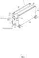
- FIG. 1 is a perspective view of a heat exchanging apparatus according to the present invention
- FIG. 2 is an exploded perspective view of the heat exchanging apparatus according to the present invention
- FIG. 3 is an enlarged detailed view of part A of FIG. 2
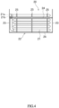
- FIG. 4 is a front view of the heat exchange unit of the heat exchanging apparatus according to the present invention
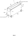
- FIG. 5 is a perspective view of the heat exchanging apparatus according to the present invention, of which the heat exchange unit is mounted, horizontally reversed from the state shown in FIG. 1
- FIG. 6 is a side view of the heat exchanging apparatus shown in FIG. 5 (namely, a view from the direction of arrow B in FIG. 5 )
- FIG. 7 is an exploded perspective view of the heat exchanging apparatus shown in FIG. 5 . It should be noted that in FIG. 7 , the description of the heat transfer medium circulation pipe 21 is omitted in part.
- the heat exchanging apparatus 1 is a heat exchanging apparatus of the falling liquid film type including as shown in FIGs. 1 and 2 , a case 10 open upward, a heat exchange unit 20 housed in the case 10, and a storage tank 30 arranged at an upper section of the case 10. Heat exchange fluid stored in the storage tank 30 drops by its dead weight onto a heat transfer medium circulation pipe 21 of the heat exchange unit 20 so as to exchange heat between the heat exchange fluid and heat transfer medium flowing through the heat transfer medium circulation pipe 21.
- the case 10 is made of a metal plate having a low thermal conductivity such as a stainless steel plate formed into an elongated rectangular box shape, and four corners of a lower section thereof are supported by height-adjustable support legs 11. It should be noted that in the following description, as shown in FIGs. 1 and 2 , the longitudinal and lateral directions of the case 10 are referred to respectively as "left-right direction” and "front-back direction”.
- a rectangular notch 12 of the same size and shape open upward is formed on each of upper ends of opposite side walls 10A, 10B on the shorter sides (namely, at both ends in the left-right direction) of the case 10. Then, on a lower section of one of the side walls 10A (on the front side, namely at the left end, in FIGs. 1 and 2 ), a pipe-shaped heat exchange fluid discharge port 13 is formed for discharging the heat exchange fluid falling into the case 10 to the outside of the case 10 as will be described later.
- a narrow flange 10a bent inward at a right angle is formed along the longitudinal direction (namely, along the left-right direction).
- a rectangular notch is formed at each two opposite positions, namely at a total of four positions, of which only two are shown in FIG. 3 , at both ends in the longitudinal direction (left-right direction) of both flanges 10a.
- Each of the notches 14 functions as a guide means for guiding the heat exchange unit 20 when the heat exchange unit 20 is vertically taken in and out of the case 10 as will be described later.
- a positioning pin 15 is erected in the vicinity of each of the notches 14 of each of the flanges 10a of the case 10.
- the heat exchange unit 20 includes the heat transfer medium circulation pipe 21 wound spirally (namely, in an oval ring shape) along the vertical direction and a rectangular frame body 22 for housing and holding the heat transfer medium circulation pipe 21.
- the rectangular frame 22 includes two left and right rectangular plate-shaped fixing plates 23 standing vertically, each two upper and lower horizontal bars 24 horizontally bridged between front ends and between rear ends of the fixing plates 23, and each three vertical bars 25 bridged vertically at appropriate intervals in the left-right direction between the two front upper and lower horizontal bars 24 and between the two rear upper and lower horizontal bars 24, in which the heat transfer medium circulation pipe 21 is housed and held.
- the heat transfer medium circulation pipe 21 circulates a heat transfer medium such as a refrigerant (water, freon, etc.) and a heating medium (steam, etc.) inside. As shown in FIG 1 ., both ends of the heat transfer medium circulation pipe 21 rise vertically along the inside of the side wall 10A at the left end of the case 10 and penetrate through one of the fixing plates 23 (namely, the left one) to be open on an upper section of the left fixing plate 23 side by side in the front-rear direction. One of the openings constitutes the heat transfer medium inlet 21a, and the other constitutes the heat transfer medium outlet 21b.
- a heat transfer medium such as a refrigerant (water, freon, etc.) and a heating medium (steam, etc.
- the heat transfer medium inlet 21a and the heat transfer medium outlet 21b of the heat transfer medium circulation pipe 21 are open side by side at the same height position on the upper section of one of the fixing plates 23 (namely, of the left one in the illustrated example) toward the same direction (namely, to the left direction in the illustrated example).
- the material of the heat transfer medium circulation pipe 21 it is preferable to select copper or copper alloy having a large thermal conductivity.
- a notched circular communication hole 23a open downward is formed at the central part in the front-rear direction of a lower end of each of the two left and right fixing plates 23. It should be noted that when the heat exchange unit 20 is housed in the case 10, one of the two communication holes 23a (namely, the left one in the illustrated example) communicates with the heat exchange fluid discharge port 13 formed on one of the side plates 10A of the case 10 (namely, on the left one in the illustrated example).
- the storage tank 30 is a rectangular tray-shaped container open upward, in which the heat exchange fluid is stored. It should be noted that a large number of small hole-shaped dripping holes are formed on the bottom surface of the storage tank 30 although they are not shown in the figure.
- each of upper end edges of front and rear side walls 30A, 30B opposed to each other on the longer side of the storage tank 30 is bent outward at a right angle to form a flange 30a.
- Positioning holes 31 are formed on both left and right ends of each flange 30a (namely, at two left and right positions corresponding to the positioning pins 15 erected on each flange 10a of the case 10).
- the heat exchange unit 20 of the heat exchanging apparatus 1 is mounted from above and thus housed in the case 10.
- the left and right fixing plates 23 of the heat exchange unit 20 are inserted and fitted into the notches 14 serving as the guide means formed at each two opposite positions of the two flanges 10a of the case 10. This enables the heat exchange unit 20 to smoothly drop down into the case 10 with no rattling while being guided by the notch 14 so as to be accurately housed in a proper position.
- the heat exchanging apparatus 1 is assembled upon placement of the flange 30a of the storage tank 30 on the flange 10a of the case 10.
- the four total positioning pins 15 formed on the flanges 10a of the case 10 are fitted into the four total positioning holes 31 formed on the flanges 30a of the storage tank 30. This enables the storage tank 30 to be placed while being accurately positioned on the upper section of the case 10.
- the heat exchange fluid discharge port 13 of the case 10 is open in the same direction as the opening direction (namely, leftward) of the heat transfer medium inlet 21a and the heat transfer medium outlet 21b of the heat transfer medium circulation pipe 21 provided in the heat exchange unit 20.
- the heat exchange fluid stored in the storage tank 30 drops onto the heat exchange unit 20 in the case 10 by its dead weight through the large number of dripping holes (not shown in the figure) formed on the bottom surface of the storage tank 30, the heat exchange fluid flows down in the form of a liquid film along the outer surface of the heat transfer medium circulation pipe 21 of the heat exchange unit 20.
- the heat transfer medium circulation pipe 21 of the heat exchange unit 20 the heat transfer medium circulates in the heat transfer medium circulation pipe 21 in the manner that the heat transfer medium flows in from the heat transfer medium inlet 21a, flows spirally from downward to upward in the heat transfer medium circulation pipe 21, and is then discharged from the heat transfer medium outlet 21b to the outside of the case 10.
- the heat exchange fluid is cooled or heated by exchanging heat with the heat transfer medium flowing through the heat transfer medium circulation pipe 21 and eventually falls down to the bottom of the case 10.
- the heat exchange fluid having exchanged heat with the heat transfer medium and fallen down to the bottom of the case 10 is discharged to the outside of the case 10 through the communication hole 23a of the fixing plate 23 and the heat exchange fluid discharge port 13 of the case 10 communicating with each other.
- the opening direction of the heat transfer medium inlet 21a and the heat transfer medium outlet 21b of the heat transfer medium circulation pipe 21 is opposed to the opening direction of the heat exchange fluid discharge port 13 formed on the case 10.
- the heat exchange unit 20 is slid upward to be taken out from the case 10 as shown in FIG. 2 , and then the heat exchange unit 20 having taken out is rotated by 180 degrees around the vertical axis to be horizontally reversed as shown in FIG. 7 . Then, the opening direction of the heat transfer medium inlet 21a and the heat transfer medium outlet 21b of the heat transfer medium circulation pipe 21 in the heat exchange unit 20 is opposed to the opening direction of the heat transfer fluid discharge port 13 formed on the case 10. In other words, as shown in FIG.
- the heat transfer medium inlet 21a and the heat transfer medium outlet 21b of the heat transfer medium circulation pipe 21 are open so as to face the notch 12 formed on the right side wall 10B of the case 10, the heat exchange fluid discharge port 13 formed on the case 10 is open on the left side of the case 10.
- the assembly of the heat exchanging apparatus 1 with the heat exchange unit 20 horizontally reversed is completed in the manner as described above, namely, by taking out the heat exchange unit 20 from the case 10 to be horizontally reversed, dropping down and then housing the heat exchange unit 20 in the case 10 as shown in FIG. 5 , and then installing the storage tank 30 on the upper section of the case 10.
- either one of these communication holes 23a communicates with the heat exchange fluid discharge port 13 of the case 10 in the heat exchanging apparatus 1 provided with the horizontally reversed heat exchange unit 20. Therefore, even when the heat exchange unit 20 is horizontally reversed, the heat exchange fluid falling into the case 10 can be discharged to the outside through the communication hole 23a on the fixing plate 23 and the heat exchange fluid discharge port 13 on the case 10.
- the heat exchange fluid stored in the storage tank 30 drops onto the heat exchange unit 20 by its dead weight inside the case 10 through the large number of dripping holes (not shown in the figure) formed on the bottom surface of the storage tank 30, the heat exchange fluid is cooled or heated by exchanging heat with the heat transfer medium flowing through the heat transfer medium circulation pipe 21 in the process of flowing down in the form of a liquid film along the outer surface of the heat transfer medium circulation pipe 21 of the heat exchange unit 20.
- the opening direction of the heat transfer medium inlet 21a and the heat transfer medium outlet 21b of the heat transfer medium circulation pipe 21 is incompatible with the opening direction of the heat exchange fluid discharge port 13 formed on the case 10 under given piping conditions at the installation site of the heat exchanging apparatus 1
- the opening direction of the heat transfer medium inlet 21a and the heat transfer medium outlet 21b and the opening direction of the heat exchange fluid discharge port 13 formed on the case 10 can be adjusted to meet the piping conditions at the installation site by taking out the heat exchange unit 20 upward from the case 1, rotating it 180 degrees around the vertical axis, and then storing it in the case 10. Accordingly, only one type of heat exchanging apparatus 1 needs to be made available, whereby man-hours for manufacturing, managing, and installing the heat exchanging apparatus 1 can be reduced for cost reduction.
- the notch 12 of the same size and shape open upward is formed at each of the upper ends of the pair of the opposite side walls 10A, 10B respectively in the same direction as and in the opposite direction to the opening direction of the heat transfer medium inlet 21a and the heat transfer medium outlet 21b so that the heat transfer medium inlet 21a and the heat transfer medium outlet 21b can face either one of the notches 12.
- the heat transfer medium inlet 21a and the heat transfer medium outlet 21b of the heat transfer medium circulation pipe 21 are open on one of the pair of the fixing plates 23 provided in the heat exchange unit 20, and the communication holes 23a, one of which communicates with the heat exchange fluid discharge port 13 on the case 10, are formed on the lower sections of both fixing plates 23.
- the notch 14 serving as the guide means is formed at the flange 10a of the case 10 for guiding a slide in the vertical direction when the heat exchange unit 20 is taken in and out, so that when taking the heat exchange unit 20 in and out of the case 10, the heat exchange unit 20 can smoothly slide up and down while being guided by the notch 14. Therefore, the heat exchange unit 20 can be taken in and out of the case 10 stably and reliably with no rattling.
- the notch 14 serving as the guiding means can be easily formed at the flange 10a of the case 10.
Landscapes
- Engineering & Computer Science (AREA)
- Physics & Mathematics (AREA)
- Thermal Sciences (AREA)
- Mechanical Engineering (AREA)
- General Engineering & Computer Science (AREA)
- Heat-Exchange Devices With Radiators And Conduit Assemblies (AREA)
Applications Claiming Priority (2)
| Application Number | Priority Date | Filing Date | Title |
|---|---|---|---|
| JP2019162877A JP6902582B2 (ja) | 2019-09-06 | 2019-09-06 | 熱交換装置 |
| PCT/JP2020/027466 WO2021044738A1 (ja) | 2019-09-06 | 2020-07-15 | 熱交換装置 |
Publications (4)
| Publication Number | Publication Date |
|---|---|
| EP4027094A1 EP4027094A1 (en) | 2022-07-13 |
| EP4027094A4 EP4027094A4 (en) | 2022-10-12 |
| EP4027094B1 true EP4027094B1 (en) | 2024-11-13 |
| EP4027094C0 EP4027094C0 (en) | 2024-11-13 |
Family
ID=74852393
Family Applications (1)
| Application Number | Title | Priority Date | Filing Date |
|---|---|---|---|
| EP20861286.1A Active EP4027094B1 (en) | 2019-09-06 | 2020-07-15 | Heat exchange device |
Country Status (9)
| Country | Link |
|---|---|
| US (1) | US12104859B2 (https=) |
| EP (1) | EP4027094B1 (https=) |
| JP (1) | JP6902582B2 (https=) |
| KR (1) | KR102654477B1 (https=) |
| CN (1) | CN114651160A (https=) |
| CA (1) | CA3152992A1 (https=) |
| ES (1) | ES2994735T3 (https=) |
| TW (1) | TWI735314B (https=) |
| WO (1) | WO2021044738A1 (https=) |
Families Citing this family (2)
| Publication number | Priority date | Publication date | Assignee | Title |
|---|---|---|---|---|
| CN113883925B (zh) * | 2021-10-18 | 2022-08-09 | 西安交通大学 | 一种均匀液膜蒸发换热器及方法 |
| JP7138384B1 (ja) | 2022-01-20 | 2022-09-16 | 株式会社スイシン | 熱交換装置 |
Family Cites Families (14)
| Publication number | Priority date | Publication date | Assignee | Title |
|---|---|---|---|---|
| JPS5028044U (https=) * | 1973-07-05 | 1975-04-01 | ||
| JPS57175935U (https=) * | 1981-04-30 | 1982-11-06 | ||
| JPH0336005Y2 (https=) | 1985-10-25 | 1991-07-31 | ||
| JPS6383585A (ja) * | 1986-09-25 | 1988-04-14 | Tameyoshi Miyano | 熱交換装置 |
| KR100482825B1 (ko) * | 2002-07-09 | 2005-04-14 | 삼성전자주식회사 | 열교환기 |
| JP4963126B2 (ja) * | 2009-06-25 | 2012-06-27 | 株式会社パロマ | スペーサ、固定部材および熱交換器 |
| CN201436545U (zh) * | 2009-07-10 | 2010-04-07 | 美的集团有限公司 | 一种饮水机冷却器 |
| JP5626522B2 (ja) | 2010-01-06 | 2014-11-19 | 一男 中野 | 流下液膜式熱交換装置 |
| JP2014214987A (ja) * | 2013-04-26 | 2014-11-17 | 株式会社ノーリツ | 熱交換器 |
| CN205228223U (zh) * | 2015-11-24 | 2016-05-11 | 浙江大川新材料股份有限公司 | 一种聚胺生产尾气吸附冷凝器 |
| KR102088586B1 (ko) * | 2016-01-25 | 2020-03-12 | 히로시 하타모토 | 열교환 장치 |
| JP6637821B2 (ja) * | 2016-04-07 | 2020-01-29 | 公立大学法人大阪 | 熱交換装置 |
| JP6892574B2 (ja) * | 2017-04-14 | 2021-06-23 | 一男 中野 | 流下液膜式熱交換装置 |
| CN208998592U (zh) * | 2018-09-19 | 2019-06-18 | 无锡市林源热交换器有限公司 | 一种便于维护的喷淋式换热器 |
-
2019
- 2019-09-06 JP JP2019162877A patent/JP6902582B2/ja active Active
-
2020
- 2020-07-15 US US17/640,852 patent/US12104859B2/en active Active
- 2020-07-15 ES ES20861286T patent/ES2994735T3/es active Active
- 2020-07-15 CA CA3152992A patent/CA3152992A1/en active Pending
- 2020-07-15 WO PCT/JP2020/027466 patent/WO2021044738A1/ja not_active Ceased
- 2020-07-15 CN CN202080062027.7A patent/CN114651160A/zh active Pending
- 2020-07-15 EP EP20861286.1A patent/EP4027094B1/en active Active
- 2020-07-15 KR KR1020227011053A patent/KR102654477B1/ko active Active
- 2020-08-20 TW TW109128354A patent/TWI735314B/zh active
Also Published As
| Publication number | Publication date |
|---|---|
| US12104859B2 (en) | 2024-10-01 |
| CA3152992A1 (en) | 2021-03-11 |
| ES2994735T3 (en) | 2025-01-30 |
| KR102654477B1 (ko) | 2024-04-04 |
| CN114651160A (zh) | 2022-06-21 |
| EP4027094A4 (en) | 2022-10-12 |
| JP2021042868A (ja) | 2021-03-18 |
| US20220341672A1 (en) | 2022-10-27 |
| WO2021044738A1 (ja) | 2021-03-11 |
| TW202111270A (zh) | 2021-03-16 |
| KR20220054421A (ko) | 2022-05-02 |
| EP4027094A1 (en) | 2022-07-13 |
| JP6902582B2 (ja) | 2021-07-14 |
| TWI735314B (zh) | 2021-08-01 |
| EP4027094C0 (en) | 2024-11-13 |
Similar Documents
| Publication | Publication Date | Title |
|---|---|---|
| EP4027094B1 (en) | Heat exchange device | |
| EP2293376B1 (en) | Battery cell assembly comprising heat exchanger with spiral flow path | |
| EP3706523B1 (en) | Cooling cabinet and cooling system | |
| US20250063686A1 (en) | Immersion-type liquid-cooling device and immersion-type liquid-cooling system | |
| KR100786127B1 (ko) | 온도조절장치 | |
| JP7847675B2 (ja) | 浸漬型液冷装置、及び液冷システム | |
| US20180163164A1 (en) | System, device and method for receiving a disposable bag | |
| EP3410055B1 (en) | Heat exchange device | |
| CN112189117B (zh) | 空气处理单元 | |
| JPS6225658Y2 (https=) | ||
| CN221488151U (zh) | 浸没式液冷装置及液冷系统 | |
| JP7138384B1 (ja) | 熱交換装置 | |
| US20160282050A1 (en) | Heat exchange apparatus | |
| CN222507749U (zh) | 一种冷却箱体 | |
| CN222017058U (zh) | 浸没式液冷装置及液冷系统 | |
| CN223447849U (zh) | 软管固定装置及机柜 | |
| CN219797580U (zh) | 一种冷凝器 | |
| CN211170886U (zh) | 恒温装置以及mocvd设备 | |
| CN214120522U (zh) | 制冷装置和制水设备 | |
| RU54228U1 (ru) | Автомат для розлива напитков | |
| EP3794290B1 (en) | Air handling unit | |
| JPH06235321A (ja) | 吐出樋管内蔵形冷却器の固定構造 | |
| CN118231861A (zh) | 一种冷却箱体 | |
| CN116544551A (zh) | 储能设备及其热管理装置 | |
| CN113710962A (zh) | 太阳能热系统 |
Legal Events
| Date | Code | Title | Description |
|---|---|---|---|
| STAA | Information on the status of an ep patent application or granted ep patent |
Free format text: STATUS: THE INTERNATIONAL PUBLICATION HAS BEEN MADE |
|
| PUAI | Public reference made under article 153(3) epc to a published international application that has entered the european phase |
Free format text: ORIGINAL CODE: 0009012 |
|
| STAA | Information on the status of an ep patent application or granted ep patent |
Free format text: STATUS: REQUEST FOR EXAMINATION WAS MADE |
|
| 17P | Request for examination filed |
Effective date: 20220329 |
|
| AK | Designated contracting states |
Kind code of ref document: A1 Designated state(s): AL AT BE BG CH CY CZ DE DK EE ES FI FR GB GR HR HU IE IS IT LI LT LU LV MC MK MT NL NO PL PT RO RS SE SI SK SM TR |
|
| A4 | Supplementary search report drawn up and despatched |
Effective date: 20220913 |
|
| RIC1 | Information provided on ipc code assigned before grant |
Ipc: F28F 9/02 20060101ALI20220907BHEP Ipc: F28F 9/00 20060101ALI20220907BHEP Ipc: F28D 7/08 20060101ALI20220907BHEP Ipc: F28D 7/02 20060101ALI20220907BHEP Ipc: F28D 5/02 20060101ALI20220907BHEP Ipc: F28D 3/02 20060101AFI20220907BHEP |
|
| DAV | Request for validation of the european patent (deleted) | ||
| DAX | Request for extension of the european patent (deleted) | ||
| STAA | Information on the status of an ep patent application or granted ep patent |
Free format text: STATUS: EXAMINATION IS IN PROGRESS |
|
| 17Q | First examination report despatched |
Effective date: 20231130 |
|
| GRAP | Despatch of communication of intention to grant a patent |
Free format text: ORIGINAL CODE: EPIDOSNIGR1 |
|
| STAA | Information on the status of an ep patent application or granted ep patent |
Free format text: STATUS: GRANT OF PATENT IS INTENDED |
|
| RAP3 | Party data changed (applicant data changed or rights of an application transferred) |
Owner name: HATAMOTO, HIROSHI Owner name: LONOVEGE CO., LTD. |
|
| INTG | Intention to grant announced |
Effective date: 20240626 |
|
| RIN1 | Information on inventor provided before grant (corrected) |
Inventor name: HATAMOTO, HIROSHI Inventor name: MITSUYASU, TADASHI |
|
| GRAS | Grant fee paid |
Free format text: ORIGINAL CODE: EPIDOSNIGR3 |
|
| GRAA | (expected) grant |
Free format text: ORIGINAL CODE: 0009210 |
|
| STAA | Information on the status of an ep patent application or granted ep patent |
Free format text: STATUS: THE PATENT HAS BEEN GRANTED |
|
| AK | Designated contracting states |
Kind code of ref document: B1 Designated state(s): AL AT BE BG CH CY CZ DE DK EE ES FI FR GB GR HR HU IE IS IT LI LT LU LV MC MK MT NL NO PL PT RO RS SE SI SK SM TR |
|
| REG | Reference to a national code |
Ref country code: GB Ref legal event code: FG4D |
|
| REG | Reference to a national code |
Ref country code: CH Ref legal event code: EP |
|
| REG | Reference to a national code |
Ref country code: DE Ref legal event code: R096 Ref document number: 602020041458 Country of ref document: DE |
|
| REG | Reference to a national code |
Ref country code: IE Ref legal event code: FG4D |
|
| U01 | Request for unitary effect filed |
Effective date: 20241113 |
|
| U07 | Unitary effect registered |
Designated state(s): AT BE BG DE DK EE FI FR IT LT LU LV MT NL PT RO SE SI Effective date: 20241118 |
|
| REG | Reference to a national code |
Ref country code: ES Ref legal event code: FG2A Ref document number: 2994735 Country of ref document: ES Kind code of ref document: T3 Effective date: 20250130 |
|
| PG25 | Lapsed in a contracting state [announced via postgrant information from national office to epo] |
Ref country code: IS Free format text: LAPSE BECAUSE OF FAILURE TO SUBMIT A TRANSLATION OF THE DESCRIPTION OR TO PAY THE FEE WITHIN THE PRESCRIBED TIME-LIMIT Effective date: 20250313 Ref country code: HR Free format text: LAPSE BECAUSE OF FAILURE TO SUBMIT A TRANSLATION OF THE DESCRIPTION OR TO PAY THE FEE WITHIN THE PRESCRIBED TIME-LIMIT Effective date: 20241113 |
|
| PG25 | Lapsed in a contracting state [announced via postgrant information from national office to epo] |
Ref country code: NO Free format text: LAPSE BECAUSE OF FAILURE TO SUBMIT A TRANSLATION OF THE DESCRIPTION OR TO PAY THE FEE WITHIN THE PRESCRIBED TIME-LIMIT Effective date: 20250213 |
|
| PG25 | Lapsed in a contracting state [announced via postgrant information from national office to epo] |
Ref country code: GR Free format text: LAPSE BECAUSE OF FAILURE TO SUBMIT A TRANSLATION OF THE DESCRIPTION OR TO PAY THE FEE WITHIN THE PRESCRIBED TIME-LIMIT Effective date: 20250214 |
|
| PG25 | Lapsed in a contracting state [announced via postgrant information from national office to epo] |
Ref country code: PL Free format text: LAPSE BECAUSE OF FAILURE TO SUBMIT A TRANSLATION OF THE DESCRIPTION OR TO PAY THE FEE WITHIN THE PRESCRIBED TIME-LIMIT Effective date: 20241113 |
|
| PG25 | Lapsed in a contracting state [announced via postgrant information from national office to epo] |
Ref country code: RS Free format text: LAPSE BECAUSE OF FAILURE TO SUBMIT A TRANSLATION OF THE DESCRIPTION OR TO PAY THE FEE WITHIN THE PRESCRIBED TIME-LIMIT Effective date: 20250213 |
|
| PG25 | Lapsed in a contracting state [announced via postgrant information from national office to epo] |
Ref country code: SM Free format text: LAPSE BECAUSE OF FAILURE TO SUBMIT A TRANSLATION OF THE DESCRIPTION OR TO PAY THE FEE WITHIN THE PRESCRIBED TIME-LIMIT Effective date: 20241113 |
|
| PG25 | Lapsed in a contracting state [announced via postgrant information from national office to epo] |
Ref country code: SK Free format text: LAPSE BECAUSE OF FAILURE TO SUBMIT A TRANSLATION OF THE DESCRIPTION OR TO PAY THE FEE WITHIN THE PRESCRIBED TIME-LIMIT Effective date: 20241113 |
|
| PG25 | Lapsed in a contracting state [announced via postgrant information from national office to epo] |
Ref country code: CZ Free format text: LAPSE BECAUSE OF FAILURE TO SUBMIT A TRANSLATION OF THE DESCRIPTION OR TO PAY THE FEE WITHIN THE PRESCRIBED TIME-LIMIT Effective date: 20241113 |
|
| PLBE | No opposition filed within time limit |
Free format text: ORIGINAL CODE: 0009261 |
|
| STAA | Information on the status of an ep patent application or granted ep patent |
Free format text: STATUS: NO OPPOSITION FILED WITHIN TIME LIMIT |
|
| 26N | No opposition filed |
Effective date: 20250814 |
|
| REG | Reference to a national code |
Ref country code: CH Ref legal event code: H13 Free format text: ST27 STATUS EVENT CODE: U-0-0-H10-H13 (AS PROVIDED BY THE NATIONAL OFFICE) Effective date: 20260224 |
|
| GBPC | Gb: european patent ceased through non-payment of renewal fee |
Effective date: 20250715 |
|
| U90 | Renewal fees not paid: noting of loss of rights |
Free format text: RENEWAL FEE NOT PAID FOR YEAR 06 Effective date: 20260223 |
|
| PG25 | Lapsed in a contracting state [announced via postgrant information from national office to epo] |
Ref country code: GB Free format text: LAPSE BECAUSE OF NON-PAYMENT OF DUE FEES Effective date: 20250715 |