EP4023978A1 - Vacuum insulated structure with sheet metal features to control vacuum bow - Google Patents
Vacuum insulated structure with sheet metal features to control vacuum bow Download PDFInfo
- Publication number
- EP4023978A1 EP4023978A1 EP21216597.1A EP21216597A EP4023978A1 EP 4023978 A1 EP4023978 A1 EP 4023978A1 EP 21216597 A EP21216597 A EP 21216597A EP 4023978 A1 EP4023978 A1 EP 4023978A1
- Authority
- EP
- European Patent Office
- Prior art keywords
- outer frame
- inner area
- cover member
- frame portion
- vacuum
- Prior art date
- Legal status (The legal status is an assumption and is not a legal conclusion. Google has not performed a legal analysis and makes no representation as to the accuracy of the status listed.)
- Granted
Links
Images




Classifications
-
- F—MECHANICAL ENGINEERING; LIGHTING; HEATING; WEAPONS; BLASTING
- F25—REFRIGERATION OR COOLING; COMBINED HEATING AND REFRIGERATION SYSTEMS; HEAT PUMP SYSTEMS; MANUFACTURE OR STORAGE OF ICE; LIQUEFACTION SOLIDIFICATION OF GASES
- F25D—REFRIGERATORS; COLD ROOMS; ICE-BOXES; COOLING OR FREEZING APPARATUS NOT OTHERWISE PROVIDED FOR
- F25D23/00—General constructional features
- F25D23/06—Walls
- F25D23/062—Walls defining a cabinet
-
- F—MECHANICAL ENGINEERING; LIGHTING; HEATING; WEAPONS; BLASTING
- F25—REFRIGERATION OR COOLING; COMBINED HEATING AND REFRIGERATION SYSTEMS; HEAT PUMP SYSTEMS; MANUFACTURE OR STORAGE OF ICE; LIQUEFACTION SOLIDIFICATION OF GASES
- F25D—REFRIGERATORS; COLD ROOMS; ICE-BOXES; COOLING OR FREEZING APPARATUS NOT OTHERWISE PROVIDED FOR
- F25D23/00—General constructional features
- F25D23/06—Walls
- F25D23/065—Details
-
- F—MECHANICAL ENGINEERING; LIGHTING; HEATING; WEAPONS; BLASTING
- F25—REFRIGERATION OR COOLING; COMBINED HEATING AND REFRIGERATION SYSTEMS; HEAT PUMP SYSTEMS; MANUFACTURE OR STORAGE OF ICE; LIQUEFACTION SOLIDIFICATION OF GASES
- F25D—REFRIGERATORS; COLD ROOMS; ICE-BOXES; COOLING OR FREEZING APPARATUS NOT OTHERWISE PROVIDED FOR
- F25D23/00—General constructional features
-
- F—MECHANICAL ENGINEERING; LIGHTING; HEATING; WEAPONS; BLASTING
- F25—REFRIGERATION OR COOLING; COMBINED HEATING AND REFRIGERATION SYSTEMS; HEAT PUMP SYSTEMS; MANUFACTURE OR STORAGE OF ICE; LIQUEFACTION SOLIDIFICATION OF GASES
- F25D—REFRIGERATORS; COLD ROOMS; ICE-BOXES; COOLING OR FREEZING APPARATUS NOT OTHERWISE PROVIDED FOR
- F25D11/00—Self-contained movable devices, e.g. domestic refrigerators
- F25D11/02—Self-contained movable devices, e.g. domestic refrigerators with cooling compartments at different temperatures
-
- F—MECHANICAL ENGINEERING; LIGHTING; HEATING; WEAPONS; BLASTING
- F25—REFRIGERATION OR COOLING; COMBINED HEATING AND REFRIGERATION SYSTEMS; HEAT PUMP SYSTEMS; MANUFACTURE OR STORAGE OF ICE; LIQUEFACTION SOLIDIFICATION OF GASES
- F25D—REFRIGERATORS; COLD ROOMS; ICE-BOXES; COOLING OR FREEZING APPARATUS NOT OTHERWISE PROVIDED FOR
- F25D2201/00—Insulation
- F25D2201/10—Insulation with respect to heat
- F25D2201/12—Insulation with respect to heat using an insulating packing material
- F25D2201/122—Insulation with respect to heat using an insulating packing material of loose fill type
-
- F—MECHANICAL ENGINEERING; LIGHTING; HEATING; WEAPONS; BLASTING
- F25—REFRIGERATION OR COOLING; COMBINED HEATING AND REFRIGERATION SYSTEMS; HEAT PUMP SYSTEMS; MANUFACTURE OR STORAGE OF ICE; LIQUEFACTION SOLIDIFICATION OF GASES
- F25D—REFRIGERATORS; COLD ROOMS; ICE-BOXES; COOLING OR FREEZING APPARATUS NOT OTHERWISE PROVIDED FOR
- F25D2201/00—Insulation
- F25D2201/10—Insulation with respect to heat
- F25D2201/12—Insulation with respect to heat using an insulating packing material
- F25D2201/124—Insulation with respect to heat using an insulating packing material of fibrous type
-
- F—MECHANICAL ENGINEERING; LIGHTING; HEATING; WEAPONS; BLASTING
- F25—REFRIGERATION OR COOLING; COMBINED HEATING AND REFRIGERATION SYSTEMS; HEAT PUMP SYSTEMS; MANUFACTURE OR STORAGE OF ICE; LIQUEFACTION SOLIDIFICATION OF GASES
- F25D—REFRIGERATORS; COLD ROOMS; ICE-BOXES; COOLING OR FREEZING APPARATUS NOT OTHERWISE PROVIDED FOR
- F25D2201/00—Insulation
- F25D2201/10—Insulation with respect to heat
- F25D2201/14—Insulation with respect to heat using subatmospheric pressure
Definitions
- the present disclosure generally relates to a vacuum insulated structure for a refrigerator, and more specifically, to cover member geometry for controlling the effects of vacuum evacuation on the structure.
- a vacuum insulated structure includes a first cover member of a unitary sheet member defining a perimeter portion, an outer frame portion defined radially inward of the perimeter portion, and an inner area surrounded and supported by the outer frame portion.
- the inner area defines a first planar level with a portion of the outer frame portion extending to a second planar level parallel to and spaced apart from the first planar level in an axial direction.
- the vacuum insulated structure further includes a second cover member of a unitary sheet and a thermal bridge interconnecting the first cover member and the second cover member at the perimeter portions thereof to define an insulating cavity therebetween.
- the insulating cavity is a sealed cavity having a vacuum drawn therefrom, and the outer frame portion deforms such that the inner area moves axially inward away from the second planar level under a force of the vacuum within the insulating cavity.
- a method of making a vacuum insulated cabinet structure includes assembling first and second cover members with a thermal bridge, at least the first cover member defining a perimeter portion, an outer frame portion defined radially inward of the perimeter portion, and an inner area surrounded and supported by the outer frame portion.
- the inner area defines a first planar level with a portion of the outer frame portion extending to a second planar level parallel to and spaced apart from the first planar level in an axially outward direction.
- Assembling the first and second cover members with the thermal bridge defines a sealed insulating cavity therebetween.
- the method further includes drawing a vacuum from the sealed insulating cavity that causes the outer frame portion to deform such that the inner area moves axially inward from the second planar level under a force of the vacuum within the insulating cavity.
- a refrigerator includes a vacuum-insulated cabinet structure having an outer wrapper with a first side defining a perimeter portion, an outer frame portion defined radially inward of the perimeter portion, and an inner area surrounded and supported by the outer frame portion.
- the inner area defines a first planar level with a portion of the outer frame portion extending to a second planar level parallel to and spaced apart from the first planar level in an axially outward direction.
- the refrigerator further includes an inner liner disposed inward of the outer wrapper and a thermal bridge interconnecting the first cover member and the second cover member at the perimeter portions thereof to define an insulating cavity therebetween.
- the insulating cavity is a sealed cavity having a vacuum drawn therefrom, and the outer frame portion deforms such that the inner area moves axially inward away from the second planar level under a force of the vacuum within the insulating cavity.
- the terms “upper,” “lower,” “right,” “left,” “rear,” “front,” “vertical,” “horizontal,” and derivatives thereof shall relate to the disclosure as oriented in FIG. 1 .
- the term “front” shall refer to the surface of the element closer to an intended viewer, and the term “rear” shall refer to the surface of the element further from the intended viewer.
- the disclosure may assume various alternative orientations, except where expressly specified to the contrary.
- the specific devices and processes illustrated in the attached drawings, and described in the following specification are simply exemplary embodiments of the inventive concepts defined in the appended claims. Hence, specific dimensions and other physical characteristics relating to the embodiments disclosed herein are not to be considered as limiting, unless the claims expressly state otherwise.
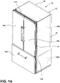
- reference numeral 12 generally designates a vacuum insulated structure for an appliance such as the refrigerator 10 illustrated in FIGS. 1A and 1B .
- the vacuum insulated structure 12 includes a first cover member of a unitary sheet member defining a perimeter portion, an outer frame portion defined radially inward of the perimeter portion, and an inner area surrounded and supported by the outer frame portion.
- the inner area defines a first planar level with a portion of the outer frame portion extending to a second planar level parallel to and spaced apart from the first planar level in an axial direction.
- the vacuum insulated structure further includes a second cover member of a unitary sheet and a thermal bridge interconnecting the first cover member and the second cover member at the perimeter portions thereof to define an insulating cavity therebetween.
- the insulating cavity is a sealed cavity having a vacuum drawn therefrom, and the outer frame portion deforms such that the inner area moves axially inward away from the second planar level under a force of the vacuum within the insulating cavity.
- a refrigerator 10 having a vacuum insulated cabinet structure 12.
- the vacuum insulated cabinet structure 12 includes one or more front openings 14A, 14B that may be closed off by doors 16A, 16B and 16C.
- the doors 16A, 16B are contemplated to pivot between open and closed positions relative to upper front opening 14A.
- door 16C is in the form of a sliding drawer which horizontally slides between open and closed positions for selectively providing access to the lower front opening 14B of the insulated cabinet structure 12.
- the vacuum insulated cabinet structure 12 includes an exterior wrapper 18 and upper and lower liners 20A, 20B.
- the upper and lower liners 20A, 20B generally indicate a refrigerator compartment and a freezer compartment, respectively.
- the upper and lower liners 20A, 20B are interconnected with the exterior wrapper 18 via a thermal bridge 22.
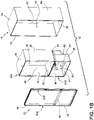
- the thermal bridge 22 is best shown in FIG. 1B .
- the exterior wrapper 18 is spaced-apart from the upper and lower liners 20A, 20B to define an insulating cavity 24 therebetween.
- the insulating cavity 24 is contemplated to be a sealed cavity that may comprise a vacuum core material such as a silica powder or other suitable loose filler material that is inserted (e.g., blown) into the insulating cavity 24 after the exterior wrapper 18, upper and lower liners 20A, 20B and thermal bridge 22 have been coupled together.
- a vacuum core material such as a silica powder or other suitable loose filler material that is inserted (e.g., blown) into the insulating cavity 24 after the exterior wrapper 18, upper and lower liners 20A, 20B and thermal bridge 22 have been coupled together.
- the thermal bridge 22 of the vacuum insulated cabinet structure 12 includes first and second side members 22A and 22B along with upper and lower openings 25, 26 which are configured to align with the upper and lower liners 20A, 20B in assembly.
- the thermal bridge 22 further includes a mullion portion 28 disposed between the upper and lower openings 25, 26 and extending between the first and second side members 22A, 22B.
- the upper liner 20A is shown having a top wall 30, a bottom wall 32, opposed side walls 34, 36 and a rear wall 38 (collectively referred to herein as sidewalls) which all cooperate to define a refrigerator compartment 40.
- the lower liner 20B includes a top wall 42, a bottom wall 44, interconnecting sidewalls 46, 48 and a rear wall 49 which all cooperate to define a freezer compartment 50.
- the rear wall 49 is shown having a stepped configuration to define a spacing 52 which may be used to house various cooling components for cooling both the refrigerator compartment 40 and the freezer compartment 50.
- the upper and lower liners 20A, 20B may be comprised of a sheet metal material that is folded and welded to define the parameters of the refrigerator compartment 40 and the freezer compartment 50.
- the exterior wrapper 18 includes a top wall 54, a bottom wall 56, opposed sidewalls 58, 60 and a rear wall 62 (collectively referred to herein as sidewalls) which together cooperate to define a receiving cavity 64.
- the exterior wrapper 18 may be comprised of a sheet metal material that is folded and/or welded to define the parameters of the receiving cavity 64 such that the wrapper 18 is generally of a unitary structure.
- the upper and lower liners 20A, 20B are received in the receiving cavity 64 of the exterior wrapper 18, such that the exterior surfaces of the upper and lower liners 20A, 20B cooperate with the inner surfaces of the exterior wrapper 18 to define the insulating cavity 24 disposed therebetween as shown in FIG. 1A .
- the insulating cavity 24 may directly receive an insulating material and have a vacuum drawn directly from the insulating cavity 24 to provide a vacuum insulating cabinet structure 12.
- the vacuum insulated cabinet structure 12 may include an overall thinner profile to maximize the amount of space available for the refrigerator compartment 40 and the freezer compartment 50 in assembly.
- the assembly 70 includes first and second cover members 72, 74 that are spaced-apart from one another and interconnected by side members 75-78.
- the side members 75-78 may be side members of a unitary frame structure to which the first and second cover members 72, 74 are attached.
- the assembly 70 includes a cavity 80 defined by the first and second cover members 72, 74 as spaced-apart from one another and interconnected by side members 75-78.
- the cavity 80 may be filled with a particulate material, such as a compressed cake of activated carbon black or silica gel, or a mixture of the two.
- These fillers are designed to fill the cavity 80 and are placed therein before a vacuum is drawn on the assembly 70.
- the filler is indicated by reference numeral 82 and is best shown in FIG. 3A .
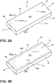
- the schematic assembly 70 has had a vacuum drawn on the cavity 80, such that the cavity 80 now defines an evacuated cavity 80.
- the first and second cover members 72, 74 have inwardly collapsed towards each other, thereby providing for a deformed outer surface 72A of first cover member 72 as shown in FIG. 2B .
- the deformation of the schematic assembly 70 shown in FIG. 2B is best depicted in FIG. 3B .
- FIG. 3A the cross-sectional view of the schematic assembly 70 shown in FIG. 2A is depicted, wherein the outer surface 72A of the first cover member 72 and an outer surface 74A of the second cover member 74 are shown in substantially planar configurations between side members 78, 76.
- This configuration shown in FIG. 3A is an ideal configuration for a vacuum insulated structure after a vacuum has been drawn on the schematic assembly 70.
- a deformed schematic assembly 70 as shown in FIGS. 2B and 3B , is often the result.
- the outer surfaces 72A, 74A of the first and second cover members 72, 74 are no longer planar outer surfaces, but rather inwardly deformed outer surfaces having specific indent deformations 84A-84D which draw the first and second cover members 72, 74 towards one another due to the low pressure of the evacuated cavity 80.
- the pressure within the evacuated cavity of panel 70 is contemplated to be less than 10 mbar as compared to an atmospheric pressure of 1 atm or 1013.25 mbar.
- the present concept includes a vacuum insulated structure having an area configured for controlled deformation, as further described below.
- a simplified version of a vacuum insulated structure 90 is shown, wherein it is contemplated that the vacuum insulated structure 90 may represent a controlled deformation technique as applied to an entire vacuum insulated structure, such as the vacuum insulated cabinet structure 12 of FIGS. 1A and 1B at the insulating cavity 24.
- the vacuum insulated structure 90 illustrates an exemplary structure having a controlled deformation technique used to provide a substantially planar structure after a vacuum has been drawn therefrom.
- the configuration of the vacuum insulated structure 90 is not meant to limit the scope of the present concept in any manner.
- the pre-deformation technique may apply to a vacuum insulated structure 90B which specifically relates to the structure of a refrigerator cabinet.
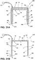
- the vacuum insulated structure 90 shown in FIGS. 2A-3B may represent a single sidewall of a vacuum insulated cabinet structure 90B shown in FIGS. 21A and 21B or opposing outer sides 92A and 92B of the cabinet structure 90B.
- FIGS. 4-8 a vacuum insulated structure 90 is shown in FIGS. 4-8 .
- FIG. 4 illustrates a first cover member 92 according to an aspect of the present disclosure, with FIG. 5 being in an exploded view having a first cover member 92 and a second cover member 94 that are spaced-apart from one another and configured to couple to a thermal bridge 96 having side members 96A-96D.
- An evacuation port 98 is shown disposed on the thermal bridge 96, but may be disposed on any part of the vacuum insulated structure 90 for accessing a cavity 100 ( FIG. 7 ).
- FIGS. 4 illustrates a first cover member 92 according to an aspect of the present disclosure
- FIG. 5 being in an exploded view having a first cover member 92 and a second cover member 94 that are spaced-apart from one another and configured to couple to a thermal bridge 96 having side members 96A-96D.
- An evacuation port 98 is shown disposed on the thermal bridge 96, but may be disposed on any
- the first and second cover members 92, 94 may include opposing outer walls (58 and 60) of the exterior wrapper 18 and/or one outer wall and corresponding portions of the upper and lower liners 20A, 20B, which are also spaced-apart from one another to define the insulating cavity 24 disposed therebetween as shown in FIG. 1A .
- the depicted thermal bridge 96 is to be understood as illustrative only such that in the application of a refrigerator outer wrapper 18, the thermal bridge 22 may be represented by side wall 96A only, with the above-described openings 25 and 26 being defined therein for receipt of the respective liners.
- the remaining side walls 96B-96D may correspond with the top, bottom, and rear walls 58,60,62 of the wrapper 18.
- the first cover member 92 includes an outer frame 102 disposed inwardly of the perimeter 104 of the first cover member 92 with the outer frame 102 surrounding an inner area 106.
- the inner area 106 defines a first planar level P1 with a portion of the outer frame portion 102 extending to a second planar level P2 parallel to and spaced apart from the first planar level in an axial direction A.
- the outer frame portion 102 includes a first side wall 102A extending from the first planar level P1 to the second planar level P2, a face wall 102C extending inwardly in the radial direction R along the second planar level P2, and a second side wall 102B extending from the second planar level P2 to join with the inner area at the first planar level P1.
- the perimeter portion 104 is also shown as being disposed at the first planar level P1. In this manner, the inner area 106 is generally suspended at the first planar level P1, including with respect to the perimeter portion 104, by the outer frame portion 102 when the first cover member 92 is in the depicted pre-assembly and pre-evacuation state.
- the second cover member 94 may be similarly formed with comparable structure and elements such that, in one aspect, the second cover member 94 may be a mirror image of the first cover member 92.
- the first and second cover members 92, 94 are contemplated to be sheet metal cover members, wherein the outer frame portions 102 are stamped portions formed by a stamping process which stretches and thins specific portions around the outer frame portions 102.
- weakened portions 93A and 93B are shown disposed around outer frame portions 102 and are contemplated to be weakened portions of the first cover member 92 having been stretched and thinned during a stamping process.
- the first cover member 92 couples to a first surface 97 of thermal bridge 96
- second cover member 94 couples to a second surface 99 of the thermal bridge 96.
- a cavity for the vacuum insulated structure 90 is formed.
- the cavity is identified as reference numeral 100 as shown in FIGS. 5-8 and is contemplated to represent a portion of insulating cavity 24 of vacuum insulated cabinet structure 12 shown in FIG. 1A .
- the vacuum insulated structure 90 is shown in an assembled condition as compared to the exploded view shown in FIG. 5 . While the vacuum insulated structure 90 shown in FIG. 6 is provided in an at-rest or pre-evacuation stage, the structure 90 is still referred to herein as a vacuum insulated structure.
- the vacuum insulated structure 90 is shown having the first and second cover members 92, 94 coupled to the first and second surfaces 97, 99 ( FIG. 5 ) of the thermal bridge 96. In this configuration, the inner areas 106 of the first and second cover members 92 and 94 remain disposed at the respective first planar levels P1.
- the vacuum insulated structure 90 includes a cavity 100 which is generally accessible via port 98 disposed in the thermal bridge 96. While the embodiment shown in FIG. 6 includes the port 98 disposed on the thermal bridge 96, it is contemplated that the port 98 can be disposed on any portion of the vacuum insulated structure 90, so long as the port provides access to the cavity 100.
- the cavity 100 can be filled with an insulation medium, such as open celled foam or a microporous filler material which may optionally include particulate reflectors or opacifiers, such as aluminum, flake or carbon black, to reduce transmission of radiation energy through the vacuum insulated structure 90.
- the cavity 100 may also be filled with an insulating material in the form of a powder comprised of fumed silica, glass beads, processed rice husks, or any combination thereof.
- the insulating material is contemplated to have a conducting coefficient or thermal conductivity of at least 5 mW/m ⁇ K, or lower, to ensure that the insulating properties of the vacuum insulated structure 90 are sound.
- This filler material or insulating material is identified in FIGS. 7 and 8 as reference numeral 102.
- the assembled vacuum insulated structure 90 is then subjected to an evacuation process, wherein the cavity 100 has been accessed via port 98 to draw a vacuum from the cavity 100, thereby providing a low pressure environment within the cavity 100.
- the low pressure environment of the cavity 100 may include a reduced internal pressure of less than 10 mbar, but may include other pressure settings conditioned on a filler material used in the vacuum insulated structure 90, and also conditioned on the desired insulative value of the vacuum insulated structure 90.
- FIG. 7 a cross-sectional view of the vacuum insulated structure 90 of FIG. 6 is shown, wherein the outer frame portions 102 of the first and second cover members 92, 94 are shown in un-deformed conditions suspending the inner areas 106 of the respective cover members 92 and 94 at the illustrated first planar levels P1.
- the face walls 102C of the outer frame portions 102 are shown extending along the second planar levels P2.
- these portions of the first and second cover members 92, 94 are more susceptible to bending or deflection as compared to the other portions of the first and second cover members 92, 94.
- the outer frame portions 102 of the first and second cover members 92, 94 deform under such forces F1,F2, particularly along side wall 102B, which allows the inner area 106 to move away from the first and second planar levels P1 and P2 in an axially inward direction.
- the first and second cover members 92, 94 are driven towards one another, whereby the outer frame portions 102 of the first and second cover members 92, 94 are bent or deflected at their weakened portions 93A, 93C, 95A, 95C, thus allowing their inner areas 106 to move away from the first and second planar levels P1, P2 in an axially inward direction.
- the vacuum insulated structure 90 is shown after an evacuation procedure has been performed, such that the cavity 100 now represents an evacuated cavity.
- the outer frame portion 102 is shown as being deformed by axially inward flexing of the side wall 102B, particularly adjacent the second side wall 102C. In this manner, the side wall 102B is angled downwardly such that the second side wall 102C has moved with respect to the first side wall 102A along the axial direction A. This movement facilitates generally even inward movement of the inner area 106 relative to the first planar level P1, as depicted in FIG. 8 .
- the deformation of the first and second cover members 92 and 94 under the vacuum draw is localized to within the outer frame portions 102 such that the effects of such deformation are generally controlled. This may help maintain the desired performance of the vacuum insulated structure 90 while preserving the desired aesthetic quality thereof.
- the first and second cover members 92 and 94 include a plurality of ribs 108 arranged in a grid pattern and extending from the outer frame portions 102 across the inner area 106.
- the ribs 108 include a set of parallel ribs 108A extending in a first direction (i.e., horizontal in the image shown in FIG. 4 ) with a second set of parallel ribs 108B extending in a second direction perpendicular to the first direction (i.e., vertical in the image shown in FIG. 4 ) to define the above-described grid pattern.
- the sets of ribs 108A and 108B are also shown as stamped features within the sheet material of the first and second cover members 92 and 94.
- the ribs 108 are shown intersecting with respective parallel ones of the second faces 102C of the outer frame portions 102.
- the second faces 102C provide structural support for the ribs 108, with the ribs 108 being generally shorter than the second faces 102C such that the presence of ribs 108 does not interfere with the above-described inward deformation of the side wall 102B.
- the stamped nature of the ribs and the generalized grid pattern defined by the intersections of the respective sets of parallel ribs 108A and 108B provides structural support for the inner area 106 to resist deformation of the first and second cover members 92 and 94 within the inner areas 106.
- the inner area moves inward in the axial direction A, as discussed above, under deformation of the outer frame 106, in a generally uniform manner, as shown in FIG. 8 .
- some deformation of the inner area 106 may occur, including along the rectangular areas between intersecting ribs 108; however, such deformation may be less than 1 mm such that it is generally imperceptible to an observer, particularly when surrounded by the visual features of the first and second cover members 92 and 94, which may visually obscure such deformation.
- the overall deformation shown in FIG. 8 may be schematically exaggerated, with the inward movement of the weakened portion 93C as well as the inward movement of the inner area 106 being less than 2 mm, and in one aspect between 1 mm and 2 mm.
- FIGS. 9A-16B a vacuum insulated structure 90A is shown according to another embodiment of the present concept.
- the vacuum insulated structure 90A includes many features similar to the vacuum insulated structure 90 shown in FIG. 4 , for which like reference numerals will be used to represent similar features.
- the vacuum insulated structure 90A is also contemplated to represent a portion of the vacuum insulated cabinet structure 12 shown in FIG. 1A .
- Representation of the concept described in FIGS. 8-9B is also shown in FIGS. 21A and 21B with particular reference to a vacuum insulated cabinet structure 90B.
- the vacuum insulated structure 90A includes first and second cover members 92, 94.
- the thermal bridge 96 includes side members 96A-96D, as well as evacuation port 98 for accessing a cavity 100 formed when the first and second cover members 92, 94 are coupled to the thermal bridge 96 at first and second surfaces 97, 99 of the thermal bridge 96.
- the first and second cover members 92, 94 may include opposing outer walls (58 and 60) of the exterior wrapper 18 and/or one outer wall and corresponding portions of the upper and lower liners 20A, 20B, which are also spaced-apart from one another to define an insulating cavity 24 disposed therebetween as shown in FIG. 1A .
- the depicted thermal bridge 96 is, again, to be understood as illustrative only such that in the application of a refrigerator outer wrapper 18, the thermal bridge 22 may be represented by side wall 96A only, with the above-described openings 25 and 26 being defined therein for receipt of the respective liners.
- the remaining side walls 96B-96D may correspond with the top, bottom, and rear walls 58,60,62 of the wrapper 18.
- FIGS. 9A-16B show various examples of the first cover member 92 according to the present embodiment.
- the first cover member 92 of each example includes an outer frame portion 102 disposed inwardly of the perimeter 104 of the first cover member 92 with the outer frame 102 surrounding an inner area 106.
- the inner area 106 defines a first planar level P1 with a portion of the outer frame portion 102 extending to a second planar level P2 parallel to and spaced apart from the first planar level in the axial direction A.
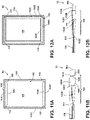
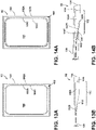
- the outer frame portion 102 includes a first stepped segment 102A extending from the first planar level P1 to a second stepped segment 102B that extends to the second planar level P2, with both stepped segments 102A and 102B being angled to also extend outwardly in the radial direction R from the inner area 106 to the perimeter 104, the perimeter portion being disposed at the second planar level P2.
- the inner area 106 is generally suspended outwardly from the perimeter 104 at the first planar level P1, including with respect to the perimeter portion 104, by the outer frame portion 102 when first cover member 92 is in the depicted pre-assembly and pre-evacuation state.
- the second cover member 94 may be similarly formed with comparable structure and elements such that, in one aspect, the second cover member 94 may be a mirror image of the first cover member 92.
- the first and second cover members 92, 94 are contemplated to be sheet metal cover members, wherein the outer frame portions 102 are stamped portions formed by a stamping process which stretches and thins specific portions around the outer frame portions 102.
- weakened portions 93A, 93B, and 93C are shown disposed between the inner area 106 and the first stepped segment 102A, between the first and second stepped segments 102A, 102B, and around the second stepped segment 102B and are contemplated to be weakened portions of the first cover member 92 having been stretched and thinned during a stamping process.
- FIGS. 10A-16B vary in the number and configuration of stepped segments 102A, 102B, ...102X, as well as the number of corresponding weakened portions 93A, 93B, ...93X ,with, for example, the arrangement shown in FIGS. 10A and 10B having an additional stepped segment 102C outward of the second stepped segment 102B with a corresponding additional weakened portion 93D outward of the weakened portion 93C between the second and third stepped segments 102B, 102C.
- the depicted first cover member 92 may vary in the corner transitions between horizontally- and vertically-extending portions of the outer frame portion 102.
- FIGS. 11A and 11B as well as the further variation of FIGS.
- FIGS. 13A-16B that include beveled corner segments 110 that may serve to reinforce the stepped portion 102A ( FIG. 11A ) or 102B ( FIG. 12A ) through which they extend.
- the outer frame portions 102 are shown having rounded corners 112. It can be appreciated that any of the additional variations depicted in the referenced figures can be substituted in the assembly of FIGS. 17-20 to achieve a similar effect to that which is illustrated therein and described below.
- the first cover member 92 couples to a first surface 97 of thermal bridge 96, while the second cover member 94 couples to a second surface 99 of the thermal bridge 96.
- a cavity for the vacuum insulated structure 90 is formed.
- the cavity is identified as reference numeral 100 as shown in FIGS. 5-8 and is contemplated to represent a portion of insulating cavity 24 of vacuum insulated cabinet structure 12 shown in FIG. 1A .
- the vacuum insulated structure 90 is shown in an assembled condition as compared to the exploded view shown in FIG. 17 . While the vacuum insulated structure 90 shown in FIG. 18A is provided in an at-rest or pre-evacuation stage, the structure 90 is still referred to herein as a vacuum insulated structure.
- the vacuum insulated structure 90 is shown having the first and second cover members 92, 94 coupled to the first and second surfaces 97, 99 ( FIG. 17 ) of the thermal bridge 96. In this configuration, the inner areas 106 of the first and second cover members 92 and 94 remain disposed at the respective first planar levels P1.
- the vacuum insulated structure 90 includes a cavity 100 which is generally accessible via port 98 disposed in the thermal bridge 96 or elsewhere in the structure 90 for evacuating air from cavity 100, as discussed above with respect to FIGS 6-8 .
- the cavity 100 can be filled with an insulation medium, as also discussed above.
- FIG. 18B when the vacuum draw is implemented, the inner area 106 moves away from the first planar level P1 to a position disposed axially inward of the second planar level P2 by inversion of the outer frame 102, particularly within the stepped segments 102A, 102B, etc., as facilitated by the corresponding weakened portions 93A, 93B, etc..
- FIG. 19 a cross-sectional view of the vacuum insulated structure 90 of FIG. 18A is shown, wherein the outer frame portions 102 of the first and second cover members 92, 94 are shown in un-deformed conditions suspending the inner areas 106 of the respective first and second cover members 92 and 94 at the illustrated first planar levels P1.
- the stepped segments 102A, 102B are shown extending axially outward from the perimeter 104 (at the second planar level P2) to support the inner area 106 at the first planar level P1.
- the first and second cover members 92, 94 are subject to inwardly directed forces F1, F2, respectively, which drive the first and second cover members 92, 94 towards one another. Due to the weakened condition of the weakened portions 93A, 93B, etc., these portions of the first and second cover members 92, 94 are more susceptible to bending or deflection as compared to the other portions of the first and second cover members 92, 94.
- the outer frame portions 102 of the first and second cover members 92, 94 deform under such forces F1,F2, particularly along stepped segments 102A, 102B, which allows the inner area 106 to move away from the first planar level P1 and pass the second planar level in the axially inward direction.
- the vacuum insulated structure 90 is shown after an evacuation procedure has been performed, such that the cavity 100 now represents an evacuated cavity.
- the outer frame portion 102 is shown as being deformed by axially inward flexing of the stepped segments 102A, 102B, at the corresponding weakened portions 93A, 93B, and 93C. In this manner, the outer frame 102 is inverted, which facilitates generally even inward movement of the inner area 106 relative to the first planar level P1, as depicted in FIG. 20 .
- the deformation of the first and second cover members 92 and 94 under the vacuum draw is localized to within the outer frame portions 102 such that the effects of such deformation are generally controlled. This may help maintain the desired performance of the vacuum insulated structure 90 while preserving the desired aesthetic quality thereof.
- the other depicted first cover members 92 from FIGS. 11A-16B would be understood as performing similarly under such conditions in such an assembly 90A.
- a vacuum insulated structure 90C is shown having exterior wrapper 18 and upper liner 20A interconnected by the thermal bridge 22 in a manner as found in FIGS. 18A and 18B described above.
- the vacuum insulated structure 90C is shown having the sidewalls 58, 60 and rear wall 62 of the exterior wrapper 18 positioned in-line with second planar level P2.
- the first and second sidewalls 34, 36 and rear wall 38 of the upper liner 20A are also shown positioned at a corresponding second planar level P2, such that the vacuum insulated structure 90C is configured in a pre-vacuum state.
- the inner areas 106 of each such panel inverts to the form shown in a similar manner to that which is described above in FIGS. 18A and 18B .
- Another aspect of the present concept includes a method of making a vacuum insulated cabinet structure, such as cabinet structures 12 and 90C.
- the method includes the steps of: 1) assembling first and second cover members 92 and 94 with a thermal bridge 96, at least the first cover member 92 defining a perimeter portion 104, an outer frame portion 102 defined radially inward of the perimeter portion 104, and an inner area 106 surrounded and supported by the outer frame portion 102.
- the inner area 106 defines a first planar level P1 with a portion of the outer frame portion 102 extending to a second planar level P2 parallel to and spaced apart from the first planar level P1 in an axially outward direction.
- Assembling the first and second cover members 92 and 94 with the thermal bridge 96 defines a sealed insulating cavity 100 therebetween.
- the method further includes the step of: 2) drawing a vacuum from the sealed insulating cavity 100 that causes the outer frame portion 102 to deform such that the inner area 106 moves axially inward from the second planar level P2 under a force of the vacuum within the insulating cavity 100.
- a vacuum insulated structure a first cover member of a unitary sheet member defining a perimeter portion, an outer frame portion defined radially inward of the perimeter portion, and an inner area surrounded and supported by the outer frame portion.
- the inner area defines a first planar level with a portion of the outer frame portion extending to a second planar level parallel to and spaced apart from the first planar level in an axial direction.
- the vacuum insulated structure further includes a second cover member of a unitary sheet and a thermal bridge interconnecting the first cover member and the second cover member at the perimeter portions thereof to define an insulating cavity therebetween.
- the insulating cavity is a sealed cavity having a vacuum drawn therefrom, and the outer frame portion deforms such that the inner area moves axially inward away from the second planar level under a force of the vacuum within the insulating cavity.
- the outer frame portion includes a first side wall extending from the first planar level to the second planar level, a face wall extending radially inwardly along the second planar level, and a second side wall extending from the second planar level to join with the inner area at the first planar level.
- the outer frame portion deforms by axially inward flexing of the face wall adjacent the second side wall such that the second side wall moves with respect to the first side wall.
- the perimeter portion is disposed at the second planar level.
- the inner area is configured to resist deformation such that deformation of the first cover member is predominantly within the outer frame portion.
- the inner area defines a plurality of ribs arranged in a grid pattern and extending from the outer frame across the inner area to provide structural support for the inner area to resist deformation.
- the second cover member defines a perimeter portion, an outer frame portion defined radially inward of the perimeter portion, and an inner area surrounded and supported by the outer frame portion.
- the inner area defining a third planar level with a portion of the outer frame portion extending to a fourth planar level parallel to and spaced apart from the third planar level in an axially outward direction.
- the outer frame portion of the second cover member deforms such that the inner area of the second cover member moves axially inward from the third and fourth planar levels under the force of the vacuum within the insulating cavity.
- the vacuum insulated structure further includes an insulating material disposed within the insulating cavity.
- the outer frame portion defines multiple stepped segments from the perimeter to the inner area and a plurality of beveled corner segments extending between the multiple stepped segments.
- a method of making a vacuum insulated cabinet structure includes assembling first and second cover members with a thermal bridge, at least the first cover member defining a perimeter portion, an outer frame portion defined radially inward of the perimeter portion, and an inner area surrounded and supported by the outer frame portion.
- the inner area defines a first planar level with a portion of the outer frame portion extending to a second planar level parallel to and spaced apart from the first planar level in an axially outward direction.
- Assembling the first and second cover members with the thermal bridge defines a sealed insulating cavity therebetween.
- the method further includes drawing a vacuum from the sealed insulating cavity that causes the outer frame portion to deform such that the inner area moves axially inward from the second planar level under a force of the vacuum within the insulating cavity.
- the first cover member is a wrapper structure defining an exterior of the cabinet structure
- the second cover member is a liner structure defining an interior of the cabinet structure.
- the first cover member defines a first exterior side on which the perimeter portion, the outer frame portion, and the inner area are defined, and the first cover member defines a second exterior side further defining an additional respective perimeter portion, outer frame portion, and inner area.
- the outer frame portion includes a first side wall extending from the first planar level to the second planar level, a face wall extending radially inwardly along the second planar level, and a second side wall extending from the second planar level to join with the inner area at the first planar level, and drawing the vacuum from the sealed insulating cavity causes the outer frame portion to deform by axially inward flexing of the face wall adjacent the second side wall such that the second side wall moves with respect to the first side wall.
- the inner area is configured to resist deformation such that drawing the vacuum from the sealed insulating cavity causes deformation of the first cover member predominantly within the outer frame portion.
- the inner area defines a plurality of ribs arranged in a grid pattern and extending from the outer frame across the inner area to provide structural support for the inner area to resist deformation.
- the method further includes introducing an insulation material into the insulting cavity.
- the insulation material includes one of fumed silica, glass beads, processed rice husks, and a combination thereof.
- a refrigerator includes a vacuum-insulated cabinet structure having an outer wrapper with a first side defining a perimeter portion, an outer frame portion defined radially inward of the perimeter portion, and an inner area surrounded and supported by the outer frame portion.
- the inner area defines a first planar level with a portion of the outer frame portion extending to a second planar level parallel to and spaced apart from the first planar level in an axially outward direction.
- the refrigerator further includes an inner liner disposed inward of the outer wrapper and a thermal bridge interconnecting the first cover member and the second cover member at the perimeter portions thereof to define an insulating cavity therebetween.
- the insulating cavity is a sealed cavity having a vacuum drawn therefrom, and the outer frame portion deforms such that the inner area moves axially inward away from the second planar level under a force of the vacuum within the insulating cavity.
- the thermal bridge surrounds an opening to an inner cavity of the refrigerator defined by the inner liner, and the refrigerator further includes at least one door operably closing the opening.
Landscapes
- Engineering & Computer Science (AREA)
- Chemical & Material Sciences (AREA)
- Combustion & Propulsion (AREA)
- Physics & Mathematics (AREA)
- Mechanical Engineering (AREA)
- Thermal Sciences (AREA)
- General Engineering & Computer Science (AREA)
- Refrigerator Housings (AREA)
- Thermal Insulation (AREA)
Abstract
Description
- The present disclosure generally relates to a vacuum insulated structure for a refrigerator, and more specifically, to cover member geometry for controlling the effects of vacuum evacuation on the structure.
- According to one aspect of the present disclosure, a vacuum insulated structure includes a first cover member of a unitary sheet member defining a perimeter portion, an outer frame portion defined radially inward of the perimeter portion, and an inner area surrounded and supported by the outer frame portion. The inner area defines a first planar level with a portion of the outer frame portion extending to a second planar level parallel to and spaced apart from the first planar level in an axial direction. The vacuum insulated structure further includes a second cover member of a unitary sheet and a thermal bridge interconnecting the first cover member and the second cover member at the perimeter portions thereof to define an insulating cavity therebetween. The insulating cavity is a sealed cavity having a vacuum drawn therefrom, and the outer frame portion deforms such that the inner area moves axially inward away from the second planar level under a force of the vacuum within the insulating cavity.
- According to another aspect of the present disclosure, a method of making a vacuum insulated cabinet structure includes assembling first and second cover members with a thermal bridge, at least the first cover member defining a perimeter portion, an outer frame portion defined radially inward of the perimeter portion, and an inner area surrounded and supported by the outer frame portion. The inner area defines a first planar level with a portion of the outer frame portion extending to a second planar level parallel to and spaced apart from the first planar level in an axially outward direction. Assembling the first and second cover members with the thermal bridge defines a sealed insulating cavity therebetween. The method further includes drawing a vacuum from the sealed insulating cavity that causes the outer frame portion to deform such that the inner area moves axially inward from the second planar level under a force of the vacuum within the insulating cavity.
- According to yet another aspect of the present disclosure, a refrigerator includes a vacuum-insulated cabinet structure having an outer wrapper with a first side defining a perimeter portion, an outer frame portion defined radially inward of the perimeter portion, and an inner area surrounded and supported by the outer frame portion. The inner area defines a first planar level with a portion of the outer frame portion extending to a second planar level parallel to and spaced apart from the first planar level in an axially outward direction. The refrigerator further includes an inner liner disposed inward of the outer wrapper and a thermal bridge interconnecting the first cover member and the second cover member at the perimeter portions thereof to define an insulating cavity therebetween. The insulating cavity is a sealed cavity having a vacuum drawn therefrom, and the outer frame portion deforms such that the inner area moves axially inward away from the second planar level under a force of the vacuum within the insulating cavity.
- These and other features, advantages, and objects of the present disclosure will be further understood and appreciated by those skilled in the art by reference to the following specification, claims, and appended drawings.
- In the drawings:
-
FIG. 1A is a isometric view of a refrigerator including a vacuum insulated cabinet structure; -
FIG. 1B is an exploded perspective view of another vacuum insulated cabinet structure; -
FIG. 2A is a top perspective view of a schematic vacuum insulated cabinet structure prior to a vacuum drawing procedure; -
FIG. 2B is a top perspective view of the schematic vacuum insulated cabinet structure ofFIG. 2A after a vacuum has been drawn; -
FIG. 3A is a cross-sectional view of the schematic vacuum insulated cabinet structure ofFIG. 2A taken at line IIIA; -
FIG. 3B is a cross-sectional view of the schematic vacuum insulated cabinet structure ofFIG. 2B taken at line IIIB; -
FIG. 4 is a side plan view of a cover member useable in connection with a vacuum insulated structure to control deformation due to vacuum draw, according to an aspect of the present disclosure; -
FIG. 5 is a an exploded top perspective view of a schematic vacuum insulated cabinet structure including the cover member ofFIG. 4 ; -
FIG. 6 is a top perspective view of the schematic vacuum insulated cabinet structure ofFIG. 5 in an assembled condition and prior to a vacuum being drawn; -
FIG. 7 is a cross-sectional view of the sidewall of the vacuum insulated cabinet structure ofFIG. 6 taken at line VII-VII inFIG 6 . -
FIG. 8 is a cross-sectional view of the sidewall of the vacuum insulated cabinet structure ofFIG. 7 after vacuum draw; -
FIGS. 9A and 9B are side pan and cross-sectional views of an alternative cover member according to a further aspect of the disclosure; -
FIGS. 10A and 10B are side pan and cross-sectional views of an alternative cover member according to a further aspect of the disclosure; -
FIGS. 11A and 11B are side pan and cross-sectional views of an alternative cover member according to a further aspect of the disclosure; -
FIGS. 12A and 12B are side pan and cross-sectional views of an alternative cover member according to a further aspect of the disclosure; -
FIGS. 13A and 13B are side pan and cross-sectional views of an alternative cover member according to a further aspect of the disclosure; -
FIGS. 14A and 14B are side pan and cross-sectional views of an alternative cover member according to a further aspect of the disclosure; -
FIGS. 15A and 15B are side pan and cross-sectional views of an alternative cover member according to a further aspect of the disclosure; -
FIGS. 16A and 16B are side pan and cross-sectional views of an alternative cover member according to a further aspect of the disclosure; -
FIG. 17 is a an exploded top perspective view of a schematic vacuum insulated cabinet structure including the cover member ofFIG. 10A ; -
FIG. 18A is a top perspective view of the schematic vacuum insulated cabinet structure ofFIG. 17 in an assembled condition and prior to a vacuum being drawn; -
FIG. 18B is a top perspective view of the schematic vacuum insulated cabinet structure ofFIG. 18A after a vacuum being drawn from the structure; -
FIG. 19 is a cross-sectional view of the sidewall of the vacuum insulated cabinet structure ofFIG. 18 taken at line XIX-XIX inFIG 18 . -
FIG. 20 is a cross-sectional view of the sidewall of the vacuum insulated cabinet structure ofFIG. 19 after vacuum draw; -
FIG. 21A is a cross-sectional view of a vacuum insulated structure according to another aspect of the disclosure; and -
FIG. 21B is a cross-sectional view of the vacuum insulated structure ofFIG. 21A after a vacuum has been drawn on the structure. - The components in the figures are not necessarily to scale, emphasis instead being placed upon illustrating the principles described herein.
- The present illustrated embodiments reside primarily in combinations of method steps and apparatus components related to a vacuum insulated structure. Accordingly, the apparatus components and method steps have been represented, where appropriate, by conventional symbols in the drawings, showing only those specific details that are pertinent to understanding the embodiments of the present disclosure so as not to obscure the disclosure with details that will be readily apparent to those of ordinary skill in the art having the benefit of the description herein. Further, like numerals in the description and drawings represent like elements.
- For purposes of description herein, the terms "upper," "lower," "right," "left," "rear," "front," "vertical," "horizontal," and derivatives thereof shall relate to the disclosure as oriented in
FIG. 1 . Unless stated otherwise, the term "front" shall refer to the surface of the element closer to an intended viewer, and the term "rear" shall refer to the surface of the element further from the intended viewer. However, it is to be understood that the disclosure may assume various alternative orientations, except where expressly specified to the contrary. It is also to be understood that the specific devices and processes illustrated in the attached drawings, and described in the following specification are simply exemplary embodiments of the inventive concepts defined in the appended claims. Hence, specific dimensions and other physical characteristics relating to the embodiments disclosed herein are not to be considered as limiting, unless the claims expressly state otherwise. - The terms "including," "comprises," "comprising," or any other variation thereof, are intended to cover a non-exclusive inclusion, such that a process, method, article, or apparatus that comprises a list of elements does not include only those elements but may include other elements not expressly listed or inherent to such process, method, article, or apparatus. An element proceeded by "comprises a . . . " does not, without more constraints, preclude the existence of additional identical elements in the process, method, article, or apparatus that comprises the element.
- Referring to
FIGS. 1A-8 ,reference numeral 12 generally designates a vacuum insulated structure for an appliance such as therefrigerator 10 illustrated inFIGS. 1A and1B . The vacuuminsulated structure 12 includes a first cover member of a unitary sheet member defining a perimeter portion, an outer frame portion defined radially inward of the perimeter portion, and an inner area surrounded and supported by the outer frame portion. The inner area defines a first planar level with a portion of the outer frame portion extending to a second planar level parallel to and spaced apart from the first planar level in an axial direction. The vacuum insulated structure further includes a second cover member of a unitary sheet and a thermal bridge interconnecting the first cover member and the second cover member at the perimeter portions thereof to define an insulating cavity therebetween. The insulating cavity is a sealed cavity having a vacuum drawn therefrom, and the outer frame portion deforms such that the inner area moves axially inward away from the second planar level under a force of the vacuum within the insulating cavity. - Referring now to
FIG. 1A , arefrigerator 10 is shown having a vacuum insulatedcabinet structure 12. The vacuum insulatedcabinet structure 12 includes one or morefront openings doors doors front opening 14A. As further found in the illustrated example,door 16C is in the form of a sliding drawer which horizontally slides between open and closed positions for selectively providing access to the lowerfront opening 14B of theinsulated cabinet structure 12. - As further shown in
FIG. 1A , the vacuum insulatedcabinet structure 12 includes anexterior wrapper 18 and upper andlower liners FIG. 1A , the upper andlower liners lower liners exterior wrapper 18 via athermal bridge 22. Thethermal bridge 22 is best shown inFIG. 1B . As further shown inFIG. 1A , theexterior wrapper 18 is spaced-apart from the upper andlower liners cavity 24 therebetween. The insulatingcavity 24 is contemplated to be a sealed cavity that may comprise a vacuum core material such as a silica powder or other suitable loose filler material that is inserted (e.g., blown) into the insulatingcavity 24 after theexterior wrapper 18, upper andlower liners thermal bridge 22 have been coupled together. - Referring now to
FIG. 1B , the vacuum insulatedcabinet structure 12 is shown in an exploded view. Thethermal bridge 22 of the vacuum insulatedcabinet structure 12 includes first andsecond side members lower openings lower liners thermal bridge 22 further includes amullion portion 28 disposed between the upper andlower openings second side members upper liner 20A is shown having atop wall 30, abottom wall 32, opposedside walls refrigerator compartment 40. Similarly, thelower liner 20B includes atop wall 42, abottom wall 44, interconnectingsidewalls rear wall 49 which all cooperate to define afreezer compartment 50. Therear wall 49 is shown having a stepped configuration to define aspacing 52 which may be used to house various cooling components for cooling both therefrigerator compartment 40 and thefreezer compartment 50. The upper andlower liners refrigerator compartment 40 and thefreezer compartment 50. - As further shown in
FIG. 1B , theexterior wrapper 18 includes atop wall 54, abottom wall 56, opposed sidewalls 58, 60 and a rear wall 62 (collectively referred to herein as sidewalls) which together cooperate to define a receivingcavity 64. Theexterior wrapper 18 may be comprised of a sheet metal material that is folded and/or welded to define the parameters of the receivingcavity 64 such that thewrapper 18 is generally of a unitary structure. In assembly, the upper andlower liners cavity 64 of theexterior wrapper 18, such that the exterior surfaces of the upper andlower liners exterior wrapper 18 to define the insulatingcavity 24 disposed therebetween as shown inFIG. 1A . The insulatingcavity 24 may directly receive an insulating material and have a vacuum drawn directly from the insulatingcavity 24 to provide a vacuum insulatingcabinet structure 12. In this way, the vacuum insulatedcabinet structure 12 may include an overall thinner profile to maximize the amount of space available for therefrigerator compartment 40 and thefreezer compartment 50 in assembly. - Referring now to
FIG. 2A , aschematic assembly 70 is used to describe a deformation effect of a vacuum drawing procedure. Theassembly 70 includes first andsecond cover members second cover members assembly 70 includes acavity 80 defined by the first andsecond cover members cavity 80 may be filled with a particulate material, such as a compressed cake of activated carbon black or silica gel, or a mixture of the two. These fillers are designed to fill thecavity 80 and are placed therein before a vacuum is drawn on theassembly 70. The filler is indicated byreference numeral 82 and is best shown inFIG. 3A . - Referring now to
FIG. 2B , theschematic assembly 70 has had a vacuum drawn on thecavity 80, such that thecavity 80 now defines an evacuatedcavity 80. By drawing the vacuum on theschematic assembly 70, the first andsecond cover members outer surface 72A offirst cover member 72 as shown inFIG. 2B . The deformation of theschematic assembly 70 shown inFIG. 2B is best depicted inFIG. 3B . - Referring now to
FIG. 3A , the cross-sectional view of theschematic assembly 70 shown inFIG. 2A is depicted, wherein theouter surface 72A of thefirst cover member 72 and anouter surface 74A of thesecond cover member 74 are shown in substantially planar configurations betweenside members FIG. 3A is an ideal configuration for a vacuum insulated structure after a vacuum has been drawn on theschematic assembly 70. However, as noted above, when a vacuum is drawn on theschematic assembly 70 ofFIGS. 2A and3A , a deformedschematic assembly 70, as shown inFIGS. 2B and3B , is often the result. With specific reference toFIG. 3B , theouter surfaces second cover members specific indent deformations 84A-84D which draw the first andsecond cover members cavity 80. The pressure within the evacuated cavity ofpanel 70 is contemplated to be less than 10 mbar as compared to an atmospheric pressure of 1 atm or 1013.25 mbar. - In an effort to avoid the vacuum deformation bow shown in the
schematic assembly 70 ofFIGS. 2A-3B , the present concept includes a vacuum insulated structure having an area configured for controlled deformation, as further described below. Specifically, in the embodiment shown inFIGS. 4-8 , a simplified version of a vacuum insulatedstructure 90 is shown, wherein it is contemplated that the vacuum insulatedstructure 90 may represent a controlled deformation technique as applied to an entire vacuum insulated structure, such as the vacuum insulatedcabinet structure 12 ofFIGS. 1A and1B at the insulatingcavity 24. As such, it is contemplated that the vacuum insulatedstructure 90 illustrates an exemplary structure having a controlled deformation technique used to provide a substantially planar structure after a vacuum has been drawn therefrom. The configuration of the vacuum insulatedstructure 90 is not meant to limit the scope of the present concept in any manner. Further, as shown inFIGS. 21A and 21B , the pre-deformation technique may apply to a vacuuminsulated structure 90B which specifically relates to the structure of a refrigerator cabinet. Thus, the vacuum insulatedstructure 90 shown inFIGS. 2A-3B may represent a single sidewall of a vacuum insulatedcabinet structure 90B shown inFIGS. 21A and 21B or opposingouter sides 92A and 92B of thecabinet structure 90B. - Thus, in accordance with the present concept, a vacuum insulated
structure 90 is shown inFIGS. 4-8 . Particularly,FIG. 4 illustrates afirst cover member 92 according to an aspect of the present disclosure, withFIG. 5 being in an exploded view having afirst cover member 92 and asecond cover member 94 that are spaced-apart from one another and configured to couple to athermal bridge 96 havingside members 96A-96D. An evacuation port 98 is shown disposed on thethermal bridge 96, but may be disposed on any part of the vacuum insulatedstructure 90 for accessing a cavity 100 (FIG. 7 ). As shown inFIGS. 4 and5 , the first andsecond cover members exterior wrapper 18 and/or one outer wall and corresponding portions of the upper andlower liners cavity 24 disposed therebetween as shown inFIG. 1A . Accordingly, the depictedthermal bridge 96 is to be understood as illustrative only such that in the application of a refrigeratorouter wrapper 18, thethermal bridge 22 may be represented byside wall 96A only, with the above-describedopenings side walls 96B-96D may correspond with the top, bottom, andrear walls wrapper 18. - The
first cover member 92 includes anouter frame 102 disposed inwardly of theperimeter 104 of thefirst cover member 92 with theouter frame 102 surrounding aninner area 106. As discussed above, and as best shown inFIGS. 7 and 8 , theinner area 106 defines a first planar level P1 with a portion of theouter frame portion 102 extending to a second planar level P2 parallel to and spaced apart from the first planar level in an axial direction A. As further shown, theouter frame portion 102 includes afirst side wall 102A extending from the first planar level P1 to the second planar level P2, aface wall 102C extending inwardly in the radial direction R along the second planar level P2, and asecond side wall 102B extending from the second planar level P2 to join with the inner area at the first planar level P1. Theperimeter portion 104 is also shown as being disposed at the first planar level P1. In this manner, theinner area 106 is generally suspended at the first planar level P1, including with respect to theperimeter portion 104, by theouter frame portion 102 when thefirst cover member 92 is in the depicted pre-assembly and pre-evacuation state. As further shown, thesecond cover member 94 may be similarly formed with comparable structure and elements such that, in one aspect, thesecond cover member 94 may be a mirror image of thefirst cover member 92. - The first and
second cover members outer frame portions 102 are stamped portions formed by a stamping process which stretches and thins specific portions around theouter frame portions 102. With specific reference tofirst cover member 92, weakenedportions outer frame portions 102 and are contemplated to be weakened portions of thefirst cover member 92 having been stretched and thinned during a stamping process. In the illustrativeschematic assembly 90, thefirst cover member 92 couples to afirst surface 97 ofthermal bridge 96, whilesecond cover member 94 couples to asecond surface 99 of thethermal bridge 96. By coupling thefirst cover member 92 and thesecond cover member 94 to thethermal bridge 96, a cavity for the vacuum insulatedstructure 90 is formed. The cavity is identified asreference numeral 100 as shown inFIGS. 5-8 and is contemplated to represent a portion of insulatingcavity 24 of vacuum insulatedcabinet structure 12 shown inFIG. 1A . - Referring now to
FIG. 6 , the vacuum insulatedstructure 90 is shown in an assembled condition as compared to the exploded view shown inFIG. 5 . While the vacuum insulatedstructure 90 shown inFIG. 6 is provided in an at-rest or pre-evacuation stage, thestructure 90 is still referred to herein as a vacuum insulated structure. In the assembled condition, the vacuum insulatedstructure 90 is shown having the first andsecond cover members second surfaces 97, 99 (FIG. 5 ) of thethermal bridge 96. In this configuration, theinner areas 106 of the first andsecond cover members FIG. 6 , the vacuum insulatedstructure 90 includes acavity 100 which is generally accessible via port 98 disposed in thethermal bridge 96. While the embodiment shown inFIG. 6 includes the port 98 disposed on thethermal bridge 96, it is contemplated that the port 98 can be disposed on any portion of the vacuum insulatedstructure 90, so long as the port provides access to thecavity 100. In assembling the vacuum insulatedstructure 90, thecavity 100 can be filled with an insulation medium, such as open celled foam or a microporous filler material which may optionally include particulate reflectors or opacifiers, such as aluminum, flake or carbon black, to reduce transmission of radiation energy through the vacuum insulatedstructure 90. Thecavity 100 may also be filled with an insulating material in the form of a powder comprised of fumed silica, glass beads, processed rice husks, or any combination thereof. The insulating material is contemplated to have a conducting coefficient or thermal conductivity of at least 5 mW/m·K, or lower, to ensure that the insulating properties of the vacuum insulatedstructure 90 are sound. This filler material or insulating material is identified inFIGS. 7 and 8 asreference numeral 102. - The assembled vacuum insulated
structure 90 is then subjected to an evacuation process, wherein thecavity 100 has been accessed via port 98 to draw a vacuum from thecavity 100, thereby providing a low pressure environment within thecavity 100. The low pressure environment of thecavity 100 may include a reduced internal pressure of less than 10 mbar, but may include other pressure settings conditioned on a filler material used in the vacuum insulatedstructure 90, and also conditioned on the desired insulative value of the vacuum insulatedstructure 90. - Referring now to
FIG. 7 , a cross-sectional view of the vacuum insulatedstructure 90 ofFIG. 6 is shown, wherein theouter frame portions 102 of the first andsecond cover members inner areas 106 of therespective cover members face walls 102C of theouter frame portions 102 are shown extending along the second planar levels P2. As a vacuum is drawn on thecavity 100 of the vacuum insulatedstructure 90, the first andsecond cover members second cover members portions second cover members second cover members cavity 100, theouter frame portions 102 of the first andsecond cover members side wall 102B, which allows theinner area 106 to move away from the first and second planar levels P1 and P2 in an axially inward direction. More generally, when the insulatingcavity 100 is evacuated, the first andsecond cover members outer frame portions 102 of the first andsecond cover members portions inner areas 106 to move away from the first and second planar levels P1, P2 in an axially inward direction. - With reference to
FIG. 8 , the vacuum insulatedstructure 90 is shown after an evacuation procedure has been performed, such that thecavity 100 now represents an evacuated cavity. Theouter frame portion 102 is shown as being deformed by axially inward flexing of theside wall 102B, particularly adjacent thesecond side wall 102C. In this manner, theside wall 102B is angled downwardly such that thesecond side wall 102C has moved with respect to thefirst side wall 102A along the axial direction A. This movement facilitates generally even inward movement of theinner area 106 relative to the first planar level P1, as depicted inFIG. 8 . In this manner, the deformation of the first andsecond cover members outer frame portions 102 such that the effects of such deformation are generally controlled. This may help maintain the desired performance of the vacuum insulatedstructure 90 while preserving the desired aesthetic quality thereof. - As further shown in
FIGS. 4-8 , the first andsecond cover members ribs 108 arranged in a grid pattern and extending from theouter frame portions 102 across theinner area 106. Theribs 108 include a set ofparallel ribs 108A extending in a first direction (i.e., horizontal in the image shown inFIG. 4 ) with a second set ofparallel ribs 108B extending in a second direction perpendicular to the first direction (i.e., vertical in the image shown inFIG. 4 ) to define the above-described grid pattern. The sets ofribs second cover members outer frame portions 102. Additionally, theribs 108 are shown intersecting with respective parallel ones of the second faces 102C of theouter frame portions 102. In this manner, the second faces 102C provide structural support for theribs 108, with theribs 108 being generally shorter than the second faces 102C such that the presence ofribs 108 does not interfere with the above-described inward deformation of theside wall 102B. The stamped nature of the ribs and the generalized grid pattern defined by the intersections of the respective sets ofparallel ribs inner area 106 to resist deformation of the first andsecond cover members inner areas 106. In this manner, the inner area moves inward in the axial direction A, as discussed above, under deformation of theouter frame 106, in a generally uniform manner, as shown inFIG. 8 . Notably, some deformation of theinner area 106 may occur, including along the rectangular areas between intersectingribs 108; however, such deformation may be less than 1 mm such that it is generally imperceptible to an observer, particularly when surrounded by the visual features of the first andsecond cover members FIG. 8 may be schematically exaggerated, with the inward movement of the weakenedportion 93C as well as the inward movement of theinner area 106 being less than 2 mm, and in one aspect between 1 mm and 2 mm. - Referring now to
FIGS. 9A-16B , a vacuuminsulated structure 90A is shown according to another embodiment of the present concept. The vacuuminsulated structure 90A includes many features similar to the vacuum insulatedstructure 90 shown inFIG. 4 , for which like reference numerals will be used to represent similar features. The vacuuminsulated structure 90A is also contemplated to represent a portion of the vacuum insulatedcabinet structure 12 shown inFIG. 1A . Representation of the concept described inFIGS. 8-9B is also shown inFIGS. 21A and 21B with particular reference to a vacuum insulatedcabinet structure 90B. As shown in the exploded view ofFIG. 17 , the vacuuminsulated structure 90A includes first andsecond cover members thermal bridge 96 includesside members 96A-96D, as well as evacuation port 98 for accessing acavity 100 formed when the first andsecond cover members thermal bridge 96 at first andsecond surfaces thermal bridge 96. As discussed above with respect to the vacuum insulated structure ofFIGS. 4 and5 , the first andsecond cover members exterior wrapper 18 and/or one outer wall and corresponding portions of the upper andlower liners cavity 24 disposed therebetween as shown inFIG. 1A . Accordingly, the depictedthermal bridge 96 is, again, to be understood as illustrative only such that in the application of a refrigeratorouter wrapper 18, thethermal bridge 22 may be represented byside wall 96A only, with the above-describedopenings side walls 96B-96D may correspond with the top, bottom, andrear walls wrapper 18. -
FIGS. 9A-16B show various examples of thefirst cover member 92 according to the present embodiment. As shown, thefirst cover member 92 of each example includes anouter frame portion 102 disposed inwardly of theperimeter 104 of thefirst cover member 92 with theouter frame 102 surrounding aninner area 106. As best shown in one example inFIG. 9B , theinner area 106 defines a first planar level P1 with a portion of theouter frame portion 102 extending to a second planar level P2 parallel to and spaced apart from the first planar level in the axial direction A. As further shown, theouter frame portion 102 includes a first steppedsegment 102A extending from the first planar level P1 to a second steppedsegment 102B that extends to the second planar level P2, with both steppedsegments inner area 106 to theperimeter 104, the perimeter portion being disposed at the second planar level P2. In this manner, theinner area 106 is generally suspended outwardly from theperimeter 104 at the first planar level P1, including with respect to theperimeter portion 104, by theouter frame portion 102 whenfirst cover member 92 is in the depicted pre-assembly and pre-evacuation state. In any assembly using the various depictedfirst cover member 92, thesecond cover member 94 may be similarly formed with comparable structure and elements such that, in one aspect, thesecond cover member 94 may be a mirror image of thefirst cover member 92. - The first and
second cover members outer frame portions 102 are stamped portions formed by a stamping process which stretches and thins specific portions around theouter frame portions 102. With specific reference to thefirst cover member 92, weakenedportions inner area 106 and the first steppedsegment 102A, between the first and second steppedsegments segment 102B and are contemplated to be weakened portions of thefirst cover member 92 having been stretched and thinned during a stamping process. As can be appreciated, the various additional cover members illustrated inFIGS. 10A-16B vary in the number and configuration of steppedsegments portions FIGS. 10A and 10B having an additional steppedsegment 102C outward of the second steppedsegment 102B with a corresponding additional weakenedportion 93D outward of the weakenedportion 93C between the second and third steppedsegments first cover member 92 may vary in the corner transitions between horizontally- and vertically-extending portions of theouter frame portion 102. In particular, the variation ofFIGS. 11A and 11B , as well as the further variation ofFIGS. 12A and 12B that includebeveled corner segments 110 that may serve to reinforce the steppedportion 102A (FIG. 11A ) or 102B (FIG. 12A ) through which they extend. In the alternative variation ofFIGS. 13A-16B , theouter frame portions 102 are shown having roundedcorners 112. It can be appreciated that any of the additional variations depicted in the referenced figures can be substituted in the assembly ofFIGS. 17-20 to achieve a similar effect to that which is illustrated therein and described below. - In the illustrative
schematic assembly 90, thefirst cover member 92 couples to afirst surface 97 ofthermal bridge 96, while thesecond cover member 94 couples to asecond surface 99 of thethermal bridge 96. By coupling thefirst cover member 92 and thesecond cover member 94 to thethermal bridge 96, a cavity for the vacuum insulatedstructure 90 is formed. The cavity is identified asreference numeral 100 as shown inFIGS. 5-8 and is contemplated to represent a portion of insulatingcavity 24 of vacuum insulatedcabinet structure 12 shown inFIG. 1A . - Referring now to
FIG. 18A , the vacuum insulatedstructure 90 is shown in an assembled condition as compared to the exploded view shown inFIG. 17 . While the vacuum insulatedstructure 90 shown inFIG. 18A is provided in an at-rest or pre-evacuation stage, thestructure 90 is still referred to herein as a vacuum insulated structure. In the assembled condition, the vacuum insulatedstructure 90 is shown having the first andsecond cover members second surfaces 97, 99 (FIG. 17 ) of thethermal bridge 96. In this configuration, theinner areas 106 of the first andsecond cover members FIG. 18 , the vacuum insulatedstructure 90 includes acavity 100 which is generally accessible via port 98 disposed in thethermal bridge 96 or elsewhere in thestructure 90 for evacuating air fromcavity 100, as discussed above with respect toFIGS 6-8 . In assembling the vacuum insulatedstructure 90, thecavity 100 can be filled with an insulation medium, as also discussed above. As shown inFIG. 18B , when the vacuum draw is implemented, theinner area 106 moves away from the first planar level P1 to a position disposed axially inward of the second planar level P2 by inversion of theouter frame 102, particularly within the steppedsegments portions - Referring now to
FIG. 19 , a cross-sectional view of the vacuum insulatedstructure 90 ofFIG. 18A is shown, wherein theouter frame portions 102 of the first andsecond cover members inner areas 106 of the respective first andsecond cover members segments inner area 106 at the first planar level P1. As the vacuum is drawn on thecavity 100 of the vacuum insulatedstructure 90, the first andsecond cover members second cover members portions second cover members second cover members cavity 100, theouter frame portions 102 of the first andsecond cover members segments inner area 106 to move away from the first planar level P1 and pass the second planar level in the axially inward direction. - With reference to
FIG. 20 , the vacuum insulatedstructure 90 is shown after an evacuation procedure has been performed, such that thecavity 100 now represents an evacuated cavity. Theouter frame portion 102 is shown as being deformed by axially inward flexing of the steppedsegments portions outer frame 102 is inverted, which facilitates generally even inward movement of theinner area 106 relative to the first planar level P1, as depicted inFIG. 20 . In this manner, the deformation of the first andsecond cover members outer frame portions 102 such that the effects of such deformation are generally controlled. This may help maintain the desired performance of the vacuum insulatedstructure 90 while preserving the desired aesthetic quality thereof. The other depictedfirst cover members 92 fromFIGS. 11A-16B would be understood as performing similarly under such conditions in such anassembly 90A. - Referring now to
FIG. 21A , a vacuum insulated structure 90C is shown havingexterior wrapper 18 andupper liner 20A interconnected by thethermal bridge 22 in a manner as found inFIGS. 18A and 18B described above. In the embodiment shown inFIG. 21A , the vacuum insulated structure 90C is shown having thesidewalls rear wall 62 of theexterior wrapper 18 positioned in-line with second planar level P2. Similarly, the first andsecond sidewalls rear wall 38 of theupper liner 20A are also shown positioned at a corresponding second planar level P2, such that the vacuum insulated structure 90C is configured in a pre-vacuum state. When the vacuum is drawn from the structure 90C, as shown inFIG. 21B , theinner areas 106 of each such panel inverts to the form shown in a similar manner to that which is described above inFIGS. 18A and 18B . - Another aspect of the present concept includes a method of making a vacuum insulated cabinet structure, such as
cabinet structures 12 and 90C. The method includes the steps of: 1) assembling first andsecond cover members thermal bridge 96, at least thefirst cover member 92 defining aperimeter portion 104, anouter frame portion 102 defined radially inward of theperimeter portion 104, and aninner area 106 surrounded and supported by theouter frame portion 102. Theinner area 106 defines a first planar level P1 with a portion of theouter frame portion 102 extending to a second planar level P2 parallel to and spaced apart from the first planar level P1 in an axially outward direction. Assembling the first andsecond cover members thermal bridge 96 defines a sealed insulatingcavity 100 therebetween. The method further includes the step of: 2) drawing a vacuum from the sealed insulatingcavity 100 that causes theouter frame portion 102 to deform such that theinner area 106 moves axially inward from the second planar level P2 under a force of the vacuum within the insulatingcavity 100. - The invention disclosed herein is further summarized in the following paragraphs and is further characterized by combinations of any and all of the various aspects described therein.
- According to another aspect of the present disclosure, a vacuum insulated structure a first cover member of a unitary sheet member defining a perimeter portion, an outer frame portion defined radially inward of the perimeter portion, and an inner area surrounded and supported by the outer frame portion. The inner area defines a first planar level with a portion of the outer frame portion extending to a second planar level parallel to and spaced apart from the first planar level in an axial direction. The vacuum insulated structure further includes a second cover member of a unitary sheet and a thermal bridge interconnecting the first cover member and the second cover member at the perimeter portions thereof to define an insulating cavity therebetween. The insulating cavity is a sealed cavity having a vacuum drawn therefrom, and the outer frame portion deforms such that the inner area moves axially inward away from the second planar level under a force of the vacuum within the insulating cavity.
- The outer frame portion includes a first side wall extending from the first planar level to the second planar level, a face wall extending radially inwardly along the second planar level, and a second side wall extending from the second planar level to join with the inner area at the first planar level.
- The outer frame portion deforms by axially inward flexing of the face wall adjacent the second side wall such that the second side wall moves with respect to the first side wall.
- The perimeter portion is disposed at the second planar level.
- The inner area is configured to resist deformation such that deformation of the first cover member is predominantly within the outer frame portion.
- The inner area defines a plurality of ribs arranged in a grid pattern and extending from the outer frame across the inner area to provide structural support for the inner area to resist deformation.
- The second cover member defines a perimeter portion, an outer frame portion defined radially inward of the perimeter portion, and an inner area surrounded and supported by the outer frame portion. The inner area defining a third planar level with a portion of the outer frame portion extending to a fourth planar level parallel to and spaced apart from the third planar level in an axially outward direction.
- The outer frame portion of the second cover member deforms such that the inner area of the second cover member moves axially inward from the third and fourth planar levels under the force of the vacuum within the insulating cavity.
- The vacuum insulated structure further includes an insulating material disposed within the insulating cavity.
- The outer frame portion defines multiple stepped segments from the perimeter to the inner area and a plurality of beveled corner segments extending between the multiple stepped segments.
- According to yet another aspect, a method of making a vacuum insulated cabinet structure includes assembling first and second cover members with a thermal bridge, at least the first cover member defining a perimeter portion, an outer frame portion defined radially inward of the perimeter portion, and an inner area surrounded and supported by the outer frame portion. The inner area defines a first planar level with a portion of the outer frame portion extending to a second planar level parallel to and spaced apart from the first planar level in an axially outward direction. Assembling the first and second cover members with the thermal bridge defines a sealed insulating cavity therebetween. The method further includes drawing a vacuum from the sealed insulating cavity that causes the outer frame portion to deform such that the inner area moves axially inward from the second planar level under a force of the vacuum within the insulating cavity.
- The first cover member is a wrapper structure defining an exterior of the cabinet structure, and the second cover member is a liner structure defining an interior of the cabinet structure.
- The first cover member defines a first exterior side on which the perimeter portion, the outer frame portion, and the inner area are defined, and the first cover member defines a second exterior side further defining an additional respective perimeter portion, outer frame portion, and inner area.
- The outer frame portion includes a first side wall extending from the first planar level to the second planar level, a face wall extending radially inwardly along the second planar level, and a second side wall extending from the second planar level to join with the inner area at the first planar level, and drawing the vacuum from the sealed insulating cavity causes the outer frame portion to deform by axially inward flexing of the face wall adjacent the second side wall such that the second side wall moves with respect to the first side wall.
- The inner area is configured to resist deformation such that drawing the vacuum from the sealed insulating cavity causes deformation of the first cover member predominantly within the outer frame portion.
- The inner area defines a plurality of ribs arranged in a grid pattern and extending from the outer frame across the inner area to provide structural support for the inner area to resist deformation.
- The method further includes introducing an insulation material into the insulting cavity.
- The insulation material includes one of fumed silica, glass beads, processed rice husks, and a combination thereof.
- According to yet another aspect, a refrigerator includes a vacuum-insulated cabinet structure having an outer wrapper with a first side defining a perimeter portion, an outer frame portion defined radially inward of the perimeter portion, and an inner area surrounded and supported by the outer frame portion. The inner area defines a first planar level with a portion of the outer frame portion extending to a second planar level parallel to and spaced apart from the first planar level in an axially outward direction. The refrigerator further includes an inner liner disposed inward of the outer wrapper and a thermal bridge interconnecting the first cover member and the second cover member at the perimeter portions thereof to define an insulating cavity therebetween. The insulating cavity is a sealed cavity having a vacuum drawn therefrom, and the outer frame portion deforms such that the inner area moves axially inward away from the second planar level under a force of the vacuum within the insulating cavity.
- The thermal bridge surrounds an opening to an inner cavity of the refrigerator defined by the inner liner, and the refrigerator further includes at least one door operably closing the opening.
Claims (15)
- A vacuum insulated structure (12, 90), comprising:a first cover member (92) of a unitary sheet member defining a perimeter portion (104), an outer frame portion (102) defined radially inward of the perimeter portion (104), and an inner area (106) surrounded and supported by the outer frame portion (102), weakened portions (93A, 93C, 95A, 95C) being defined between at least one of the perimeter portion (104) and the outer frame portion (102) or between the outer frame portion (102) and the inner area (106), the inner area (106) defining a first planar level (P1) with a portion of the outer frame portion (102) extending to a second planar level (P2) parallel to and spaced apart from the first planar level (P1) in an axial direction (A);a second cover member (94) of a unitary sheet, wherein said second cover member is preferably a mirror image of the first cover member (92); anda thermal bridge (96) interconnecting the first cover member (92) and the second cover member (94) at the perimeter portions (104) thereof to define an insulating cavity (24, 100) therebetween, wherein the insulating cavity (24, 100) is a sealed cavity and wherein, when the insulating cavity (24, 100) is evacuated, the first and second cover members (92, 94) are driven towards one another, whereby the outer frame portions (102) of the first and second cover members (92, 94) are bent or deflected at their weakened portions (93A, 93C, 95A, 95C) allowing their inner areas (106) to move away from the first and second planar levels (P1, P2) in an axially inward direction.
- The vacuum insulated structure (12, 90) of claim 1, wherein the outer frame portion (102) includes a first side wall (102A) extending from the first planar level (P1) to the second planar level (P2), a face wall (102C) extending radially inwardly along the second planar level (P2), and a second side wall (102B) extending from the second planar level (P2) to join with the inner area (106) at the first planar level (P1), a first of the at least one weakened portion (93A, 93C) being defined between the first side wall (102A) and the face wall (102C), and a second of the at least one weakened portion (95A, 95C) being defined between the face wall (102C) and the second side wall (102B).
- The vacuum insulated structure (12, 90) of claim 2, wherein the outer frame portion (102) deforms by axially inward flexing of the face wall (102C) at the second of the at least one weakened portion (95A, 95C) adjacent the second side wall (102B) such that the second side wall (102B) moves with respect to the first side wall (102A).
- The vacuum insulated structure (12, 90) of either claim 2 or claim 3, wherein the perimeter portion (104) is disposed at the second planar level (P2).
- The vacuum insulated structure (12, 90) of any of the preceding claims, wherein the inner area (106) is configured to resist deformation such that deformation of the first cover member (92) is predominantly within the outer frame portion (102).
- The vacuum insulated structure (12, 90) of claim 5, wherein the inner area (106) defines a plurality of ribs (108) arranged in a grid pattern and extending from the outer frame (102) across the inner area (106) to provide structural support for the inner area (106) to resist deformation.
- The vacuum insulated structure (12, 90) of any of claims 1 to 4, wherein the second cover member (94) defines a perimeter portion (104), an outer frame portion (102) defined radially inward of the perimeter portion (104), and an inner area (106) surrounded and supported by the outer frame portion (102) with at least one weakened portion (93A, 93C, 95A, 95C) of the second cover member (92) being defined at least one of between the perimeter portion and the outer frame portion or between the outer frame portion and the inner area, the inner area (106) defining a third planar level with a portion of the outer frame portion (102) extending to a fourth planar level parallel to and spaced apart from the third planar level in an axially outward direction.
- The vacuum insulated structure (12, 90) of claim 7, wherein the outer frame portion (102) of the second cover member (94) is deformed within the at least one weakened portion (93A, 93C, 95A, 95C) such that the inner area (106) of the second cover member (94) is moved axially inward from the third and fourth planar levels under the force of the vacuum within the insulating cavity (24).
- The vacuum insulated structure (12, 90) of any of the preceding claims, further including an insulating material disposed within the insulating cavity (24).
- The vacuum insulated structure (12, 90) of any of claims 1 to 4, wherein the outer frame portion (102) defines multiple stepped segments (102A, 102B) from the perimeter to the inner area (106) and a plurality of beveled corner segments extending between the multiple stepped segments, the at least one weakened portion (93A, 93C, 95A, 95C) being defined around at least one of the multiple stepped segments (102A, 102B).
- The vacuum insulated structure (12, 90) of any of the preceding claims, wherein:the first and second cover members (92, 94) are assembled with the thermal bridge (96) to seal the insulating cavity (24) therebetween; andthe vacuum is drawn from the sealed insulating cavity (24), causing the outer frame portion (102) to deform within the at least one weakened portion and (93A, 93C, 95A, 95C) such that the inner area (106) moves axially inward from the first and second planar levels (P1, P2) under a force of the vacuum within the insulating cavity (24).
- The vacuum insulated structure (12, 90) of claim 11, wherein:the outer frame portion (102) includes a first side wall (102A) extending from the first planar level (P1) to the second planar level (P2), a face wall (102C) extending radially inwardly along the second planar level (P2), and a second side wall (102B) extending from the second planar level (P2) to join with the inner area (106) at the first planar level (P1), a first of the at least one weakened portion (93A, 93C) being defined between the first side wall (102A) and the face wall (102C), and a second of the at least one weakened portion (95A, 95C) being defined between the face wall (102C) and the second side wall (102B); anddrawing the vacuum from the sealed insulating cavity (24) causes the outer frame portion (102) to deform by axially inward flexing of the face wall (102C) at the second of the at least one weakened portion (95A, 95C) adjacent the second side wall (102B) such that the second side wall (102B) moves with respect to the first side wall (102A).
- The vacuum insulated structure (12, 90) of claim 11 or claim 12, wherein the inner area (106) is configured to resist deformation such that drawing the vacuum from the sealed insulating cavity (24) causes deformation of the first cover member (92) predominantly within the outer frame portion (102).
- The vacuum insulated structure (12, 90) of claim 13, wherein the inner area (106) defines a plurality of ribs (108) arranged in a grid pattern and extending from the outer frame portion (102) across the inner area (106) to provide structural support for the inner area (106) to resist deformation.
- A refrigerator (10), comprising:
the vacuum-insulated structure (12, 90) of any of the preceding claims, wherein:the first cover member (92) is an outer wrapper (18);the second cover member (94) is an inner liner (20A) disposed inward of the outer wrapper (18); andthe thermal bridge (22) interconnects the outer wrapper (18) and the inner liner (20A) at the perimeter portions (104) thereof to define the insulating cavity (100) therebetween, the thermal bridge (22) surrounding an opening (25, 26) to an inner cavity (100) of the refrigerator (10) defined by the inner liner (20A), the refrigerator (10) further including at least one door (16A, 16B, 16C) operably closing the opening (25, 26).
Applications Claiming Priority (1)
| Application Number | Priority Date | Filing Date | Title |
|---|---|---|---|
| US17/136,147 US11614271B2 (en) | 2020-12-29 | 2020-12-29 | Vacuum insulated structure with sheet metal features to control vacuum bow |
Publications (2)
| Publication Number | Publication Date |
|---|---|
| EP4023978A1 true EP4023978A1 (en) | 2022-07-06 |
| EP4023978B1 EP4023978B1 (en) | 2024-10-30 |
Family
ID=79018603
Family Applications (1)
| Application Number | Title | Priority Date | Filing Date |
|---|---|---|---|
| EP21216597.1A Active EP4023978B1 (en) | 2020-12-29 | 2021-12-21 | Vacuum insulated structure and refrigerator |
Country Status (3)
| Country | Link |
|---|---|
| US (2) | US11614271B2 (en) |
| EP (1) | EP4023978B1 (en) |
| CN (1) | CN114754536A (en) |
Families Citing this family (5)
| Publication number | Priority date | Publication date | Assignee | Title |
|---|---|---|---|---|
| KR102466446B1 (en) | 2017-12-13 | 2022-11-11 | 엘지전자 주식회사 | Vacuum adiabatic body and refrigerator |
| KR102466448B1 (en) | 2017-12-13 | 2022-11-11 | 엘지전자 주식회사 | Vacuum adiabatic body and refrigerator |
| KR102511095B1 (en) * | 2017-12-13 | 2023-03-16 | 엘지전자 주식회사 | Vacuum adiabatic body and refrigerator |
| KR102530909B1 (en) | 2017-12-13 | 2023-05-11 | 엘지전자 주식회사 | Vacuum adiabatic body and refrigerator |
| KR102568737B1 (en) | 2017-12-13 | 2023-08-21 | 엘지전자 주식회사 | Vacuum adiabatic body and refrigerator |
Citations (3)
| Publication number | Priority date | Publication date | Assignee | Title |
|---|---|---|---|---|
| DE956899C (en) * | 1952-10-28 | 1957-01-24 | Gen Electric | Heat isolator |
| US10697698B2 (en) * | 2016-12-23 | 2020-06-30 | Whirlpool Corporation | Vacuum insulated panel for counteracting vacuum bow induced deformations |
| US20200370702A1 (en) * | 2019-05-21 | 2020-11-26 | Whirlpool Corporation | Collapsible pattern |
Family Cites Families (39)
| Publication number | Priority date | Publication date | Assignee | Title |
|---|---|---|---|---|
| GB760338A (en) | 1952-10-28 | 1956-10-31 | Gen Electric | Improvements in and relating to insulating structures |
| US4536990A (en) * | 1982-05-17 | 1985-08-27 | Sundstrand Corporation | Torsionally stiff lightweight refrigerator/freezer door |
| SE501701C2 (en) * | 1993-09-29 | 1995-04-24 | Electrolux Ab | Ways to fill and pack insulating powder into the walls of a cabinet body |
| GB2331838A (en) * | 1997-11-24 | 1999-06-02 | Coolbox | Portable,thermoelectric,temperature controlled receptacles. |
| US6230500B1 (en) | 1999-09-29 | 2001-05-15 | Mve, Inc. | Cryogenic freezer |
| KR100541061B1 (en) | 2002-12-27 | 2006-01-11 | 제일모직주식회사 | Multilayer Sheet for Refrigerator Interior with Metal Texture |
| JP4580843B2 (en) | 2005-08-24 | 2010-11-17 | 日立アプライアンス株式会社 | Vacuum heat insulating material and refrigerator using the same |
| KR101898487B1 (en) * | 2010-10-28 | 2018-10-04 | 엘지전자 주식회사 | A refrigerator comprising a vaccum space |
| JP6005341B2 (en) | 2011-06-13 | 2016-10-12 | 東芝ライフスタイル株式会社 | refrigerator |
| JP5689387B2 (en) | 2011-08-30 | 2015-03-25 | 日立アプライアンス株式会社 | Refrigerator and manufacturing method thereof |
| JP2013088036A (en) | 2011-10-19 | 2013-05-13 | Hitachi Appliances Inc | Thermal insulation box, refrigerator, and storage type water heater |
| US8986483B2 (en) | 2012-04-02 | 2015-03-24 | Whirlpool Corporation | Method of making a folded vacuum insulated structure |
| EP2765375B1 (en) | 2013-02-06 | 2018-09-12 | Samsung Electronics Co., Ltd | Vacuum insulation material, insulation case unit, and refrigerator |
| US20140360603A1 (en) * | 2013-06-10 | 2014-12-11 | The Cola-Cola Company | Systems and methods for a vacuum insulated panel |
| JP5907204B2 (en) * | 2013-07-19 | 2016-04-26 | 大日本印刷株式会社 | Manufacturing method of vacuum insulation |
| US9574819B2 (en) | 2014-01-07 | 2017-02-21 | Samsung Electronics Co., Ltd. | Refrigerator |
| US9498072B2 (en) | 2014-02-11 | 2016-11-22 | Anthony, Inc. | Display case door assembly with tempered glass vacuum panel |
| KR102236776B1 (en) * | 2014-09-05 | 2021-04-06 | 삼성전자주식회사 | An evaporator, an refrigerator using the evaporator and a method for controlling the refrigerator |
| US20160258671A1 (en) * | 2015-03-02 | 2016-09-08 | Whirlpool Corporation | Gas barrier for vacuum insulation |
| EP3270032A4 (en) | 2015-03-10 | 2018-10-17 | Toshiba Lifestyle Products & Services Corporation | Vacuum insulated panel, core material, and refrigerator |
| US10018406B2 (en) | 2015-12-28 | 2018-07-10 | Whirlpool Corporation | Multi-layer gas barrier materials for vacuum insulated structure |
| US10807298B2 (en) * | 2015-12-29 | 2020-10-20 | Whirlpool Corporation | Molded gas barrier parts for vacuum insulated structure |
| US11247369B2 (en) | 2015-12-30 | 2022-02-15 | Whirlpool Corporation | Method of fabricating 3D vacuum insulated refrigerator structure having core material |
| US10830526B2 (en) * | 2016-09-26 | 2020-11-10 | Whirlpool Corporation | Vacuum generating system for an appliance incorporating a vacuum insulated structure |
| EP3519745B1 (en) * | 2016-09-28 | 2022-09-21 | Whirlpool Corporation | Operable panel for an appliance having stamped components |
| US10906231B2 (en) * | 2016-09-30 | 2021-02-02 | Whirlpool Corporation | Method for forming a vacuum insulated structure |
| EP3519746B1 (en) | 2016-10-03 | 2022-10-26 | Whirlpool Corporation | Encapsulation system for a thermal bridge breaker-to-metal liner |
| EP3523584B1 (en) * | 2016-10-04 | 2022-08-24 | Whirlpool Corporation | Structural formations incorporated within a vacuum insulated structure |
| WO2018074986A1 (en) * | 2016-10-17 | 2018-04-26 | Whirlpool Corporation | Insulating core material having coated insulated spheres and a process for making the insulating core material |
| CN106693623B (en) * | 2016-12-02 | 2019-12-10 | 青岛海尔股份有限公司 | Air separation device and refrigerating and freezing device |
| EP3559571A4 (en) * | 2016-12-23 | 2020-08-26 | Whirlpool Corporation | Vacuum insulated structures having internal chamber structures |
| WO2018136054A1 (en) | 2017-01-18 | 2018-07-26 | Whirlpool Corporation | Use of rigid or permeable conduits for achieving faster vacuum evacuation time in vacuum insulated structures |
| KR102511095B1 (en) * | 2017-12-13 | 2023-03-16 | 엘지전자 주식회사 | Vacuum adiabatic body and refrigerator |
| US10746343B2 (en) * | 2018-09-28 | 2020-08-18 | Whirlpool Corporation | Channel system for a vacuum insulated structure |
| US11300238B2 (en) * | 2019-01-21 | 2022-04-12 | Whirlpool Corporation | Vacuum insulated structure with filter features in a vacuum cavity |
| WO2020157825A1 (en) | 2019-01-29 | 2020-08-06 | 三菱電機株式会社 | Refrigerator |
| US10697696B1 (en) * | 2019-02-25 | 2020-06-30 | Whirlpool Corporation | Vacuum insulated structure with internal airway system |
| US10605520B1 (en) * | 2019-03-25 | 2020-03-31 | Whirlpool Corporation | Vacuum insulation assembly for an appliance |
| CN111502506B (en) * | 2020-05-22 | 2025-08-05 | 杭州富士达特种材料股份有限公司 | A thermal insulation material structure and thermal insulation door body |
-
2020
- 2020-12-29 US US17/136,147 patent/US11614271B2/en active Active
-
2021
- 2021-12-21 EP EP21216597.1A patent/EP4023978B1/en active Active
- 2021-12-29 CN CN202111639352.8A patent/CN114754536A/en active Pending
-
2023
- 2023-02-27 US US18/114,517 patent/US11808514B2/en active Active
Patent Citations (3)
| Publication number | Priority date | Publication date | Assignee | Title |
|---|---|---|---|---|
| DE956899C (en) * | 1952-10-28 | 1957-01-24 | Gen Electric | Heat isolator |
| US10697698B2 (en) * | 2016-12-23 | 2020-06-30 | Whirlpool Corporation | Vacuum insulated panel for counteracting vacuum bow induced deformations |
| US20200370702A1 (en) * | 2019-05-21 | 2020-11-26 | Whirlpool Corporation | Collapsible pattern |
Also Published As
| Publication number | Publication date |
|---|---|
| US20220205708A1 (en) | 2022-06-30 |
| US11614271B2 (en) | 2023-03-28 |
| US11808514B2 (en) | 2023-11-07 |
| EP4023978B1 (en) | 2024-10-30 |
| US20230204279A1 (en) | 2023-06-29 |
| CN114754536A (en) | 2022-07-15 |
Similar Documents
| Publication | Publication Date | Title |
|---|---|---|
| EP4023978B1 (en) | Vacuum insulated structure and refrigerator | |
| US20210310723A1 (en) | Vacuum insulated panel for counteracting vacuum bow induced deformations | |
| AU2021245189B2 (en) | Vacuum adiabatic body and refrigerator | |
| US12392545B2 (en) | Vacuum adiabatic body and refrigerator | |
| EP4027088B1 (en) | Vacuum insulated refrigerator structure with feature for controlling deformation and improved air withdrawal | |
| US11378223B2 (en) | Vacuum adiabatic body and refrigerator | |
| US9835369B2 (en) | Vacuum insulated structure tubular cabinet construction | |
| US10274203B2 (en) | Arrangement of glass panels for a heat insulated oven door for a cooking oven | |
| AU2016301916B2 (en) | Vacuum adiabatic body and refrigerator | |
| RU2769247C1 (en) | Vacuum adiabatic body and refrigerator | |
| US20220127898A1 (en) | Vacuum glazing and method for manufacturing the same | |
| US20250044020A1 (en) | Vacuum adiabatic module and refrigerator | |
| US20190264859A1 (en) | Vacuum insulated structures having internal chamber structures | |
| EP4502511A1 (en) | Support system for a vacuum insulated panel | |
| JP5886017B2 (en) | Vacuum insulation panel and refrigerator using the same | |
| US20250164175A1 (en) | Trimbreaker ladder cover | |
| US20260104127A1 (en) | Expandable insulating packets for use as an insulation material within a vacuum insulated structure | |
| JP3869765B2 (en) | Heat insulation box | |
| JP2000018809A (en) | Storehouse |
Legal Events
| Date | Code | Title | Description |
|---|---|---|---|
| PUAI | Public reference made under article 153(3) epc to a published international application that has entered the european phase |
Free format text: ORIGINAL CODE: 0009012 |
|
| STAA | Information on the status of an ep patent application or granted ep patent |
Free format text: STATUS: THE APPLICATION HAS BEEN PUBLISHED |
|
| AK | Designated contracting states |
Kind code of ref document: A1 Designated state(s): AL AT BE BG CH CY CZ DE DK EE ES FI FR GB GR HR HU IE IS IT LI LT LU LV MC MK MT NL NO PL PT RO RS SE SI SK SM TR |
|
| STAA | Information on the status of an ep patent application or granted ep patent |
Free format text: STATUS: REQUEST FOR EXAMINATION WAS MADE |
|
| 17P | Request for examination filed |
Effective date: 20221213 |
|
| RBV | Designated contracting states (corrected) |
Designated state(s): AL AT BE BG CH CY CZ DE DK EE ES FI FR GB GR HR HU IE IS IT LI LT LU LV MC MK MT NL NO PL PT RO RS SE SI SK SM TR |
|
| RAP3 | Party data changed (applicant data changed or rights of an application transferred) |
Owner name: WHIRLPOOL CORPORATION |
|
| GRAP | Despatch of communication of intention to grant a patent |
Free format text: ORIGINAL CODE: EPIDOSNIGR1 |
|
| STAA | Information on the status of an ep patent application or granted ep patent |
Free format text: STATUS: GRANT OF PATENT IS INTENDED |
|
| RIC1 | Information provided on ipc code assigned before grant |
Ipc: F16L 59/065 20060101ALI20240501BHEP Ipc: E04B 1/76 20060101ALI20240501BHEP Ipc: F25D 23/06 20060101AFI20240501BHEP |
|
| INTG | Intention to grant announced |
Effective date: 20240521 |
|
| GRAS | Grant fee paid |
Free format text: ORIGINAL CODE: EPIDOSNIGR3 |
|
| GRAA | (expected) grant |
Free format text: ORIGINAL CODE: 0009210 |
|
| STAA | Information on the status of an ep patent application or granted ep patent |
Free format text: STATUS: THE PATENT HAS BEEN GRANTED |
|
| P01 | Opt-out of the competence of the unified patent court (upc) registered |
Free format text: CASE NUMBER: APP_49085/2024 Effective date: 20240828 |
|
| AK | Designated contracting states |
Kind code of ref document: B1 Designated state(s): AL AT BE BG CH CY CZ DE DK EE ES FI FR GB GR HR HU IE IS IT LI LT LU LV MC MK MT NL NO PL PT RO RS SE SI SK SM TR |
|
| REG | Reference to a national code |
Ref country code: GB Ref legal event code: FG4D |
|
| REG | Reference to a national code |
Ref country code: CH Ref legal event code: EP |
|
| REG | Reference to a national code |
Ref country code: IE Ref legal event code: FG4D |
|
| REG | Reference to a national code |
Ref country code: DE Ref legal event code: R096 Ref document number: 602021020958 Country of ref document: DE |
|
| PGFP | Annual fee paid to national office [announced via postgrant information from national office to epo] |
Ref country code: FR Payment date: 20241227 Year of fee payment: 4 |
|
| REG | Reference to a national code |
Ref country code: LT Ref legal event code: MG9D |
|
| REG | Reference to a national code |
Ref country code: NL Ref legal event code: MP Effective date: 20241030 |
|
| PG25 | Lapsed in a contracting state [announced via postgrant information from national office to epo] |
Ref country code: HR Free format text: LAPSE BECAUSE OF FAILURE TO SUBMIT A TRANSLATION OF THE DESCRIPTION OR TO PAY THE FEE WITHIN THE PRESCRIBED TIME-LIMIT Effective date: 20241030 Ref country code: IS Free format text: LAPSE BECAUSE OF FAILURE TO SUBMIT A TRANSLATION OF THE DESCRIPTION OR TO PAY THE FEE WITHIN THE PRESCRIBED TIME-LIMIT Effective date: 20250228 Ref country code: PT Free format text: LAPSE BECAUSE OF FAILURE TO SUBMIT A TRANSLATION OF THE DESCRIPTION OR TO PAY THE FEE WITHIN THE PRESCRIBED TIME-LIMIT Effective date: 20250228 |
|
| PG25 | Lapsed in a contracting state [announced via postgrant information from national office to epo] |
Ref country code: NL Free format text: LAPSE BECAUSE OF FAILURE TO SUBMIT A TRANSLATION OF THE DESCRIPTION OR TO PAY THE FEE WITHIN THE PRESCRIBED TIME-LIMIT Effective date: 20241030 Ref country code: FI Free format text: LAPSE BECAUSE OF FAILURE TO SUBMIT A TRANSLATION OF THE DESCRIPTION OR TO PAY THE FEE WITHIN THE PRESCRIBED TIME-LIMIT Effective date: 20241030 |
|
| REG | Reference to a national code |
Ref country code: AT Ref legal event code: MK05 Ref document number: 1737228 Country of ref document: AT Kind code of ref document: T Effective date: 20241030 |
|
| PG25 | Lapsed in a contracting state [announced via postgrant information from national office to epo] |
Ref country code: BG Free format text: LAPSE BECAUSE OF FAILURE TO SUBMIT A TRANSLATION OF THE DESCRIPTION OR TO PAY THE FEE WITHIN THE PRESCRIBED TIME-LIMIT Effective date: 20241030 |
|
| PG25 | Lapsed in a contracting state [announced via postgrant information from national office to epo] |
Ref country code: ES Free format text: LAPSE BECAUSE OF FAILURE TO SUBMIT A TRANSLATION OF THE DESCRIPTION OR TO PAY THE FEE WITHIN THE PRESCRIBED TIME-LIMIT Effective date: 20241030 |
|
| PG25 | Lapsed in a contracting state [announced via postgrant information from national office to epo] |
Ref country code: NO Free format text: LAPSE BECAUSE OF FAILURE TO SUBMIT A TRANSLATION OF THE DESCRIPTION OR TO PAY THE FEE WITHIN THE PRESCRIBED TIME-LIMIT Effective date: 20250130 |
|
| PG25 | Lapsed in a contracting state [announced via postgrant information from national office to epo] |
Ref country code: LV Free format text: LAPSE BECAUSE OF FAILURE TO SUBMIT A TRANSLATION OF THE DESCRIPTION OR TO PAY THE FEE WITHIN THE PRESCRIBED TIME-LIMIT Effective date: 20241030 Ref country code: AT Free format text: LAPSE BECAUSE OF FAILURE TO SUBMIT A TRANSLATION OF THE DESCRIPTION OR TO PAY THE FEE WITHIN THE PRESCRIBED TIME-LIMIT Effective date: 20241030 Ref country code: GR Free format text: LAPSE BECAUSE OF FAILURE TO SUBMIT A TRANSLATION OF THE DESCRIPTION OR TO PAY THE FEE WITHIN THE PRESCRIBED TIME-LIMIT Effective date: 20250131 |
|
| PG25 | Lapsed in a contracting state [announced via postgrant information from national office to epo] |
Ref country code: PL Free format text: LAPSE BECAUSE OF FAILURE TO SUBMIT A TRANSLATION OF THE DESCRIPTION OR TO PAY THE FEE WITHIN THE PRESCRIBED TIME-LIMIT Effective date: 20241030 |
|
| PG25 | Lapsed in a contracting state [announced via postgrant information from national office to epo] |
Ref country code: RS Free format text: LAPSE BECAUSE OF FAILURE TO SUBMIT A TRANSLATION OF THE DESCRIPTION OR TO PAY THE FEE WITHIN THE PRESCRIBED TIME-LIMIT Effective date: 20250130 |
|
| PG25 | Lapsed in a contracting state [announced via postgrant information from national office to epo] |
Ref country code: SM Free format text: LAPSE BECAUSE OF FAILURE TO SUBMIT A TRANSLATION OF THE DESCRIPTION OR TO PAY THE FEE WITHIN THE PRESCRIBED TIME-LIMIT Effective date: 20241030 |
|
| PG25 | Lapsed in a contracting state [announced via postgrant information from national office to epo] |
Ref country code: MC Free format text: LAPSE BECAUSE OF FAILURE TO SUBMIT A TRANSLATION OF THE DESCRIPTION OR TO PAY THE FEE WITHIN THE PRESCRIBED TIME-LIMIT Effective date: 20241030 |
|
| PG25 | Lapsed in a contracting state [announced via postgrant information from national office to epo] |
Ref country code: DK Free format text: LAPSE BECAUSE OF FAILURE TO SUBMIT A TRANSLATION OF THE DESCRIPTION OR TO PAY THE FEE WITHIN THE PRESCRIBED TIME-LIMIT Effective date: 20241030 |
|
| PG25 | Lapsed in a contracting state [announced via postgrant information from national office to epo] |
Ref country code: EE Free format text: LAPSE BECAUSE OF FAILURE TO SUBMIT A TRANSLATION OF THE DESCRIPTION OR TO PAY THE FEE WITHIN THE PRESCRIBED TIME-LIMIT Effective date: 20241030 |
|
| PG25 | Lapsed in a contracting state [announced via postgrant information from national office to epo] |
Ref country code: RO Free format text: LAPSE BECAUSE OF FAILURE TO SUBMIT A TRANSLATION OF THE DESCRIPTION OR TO PAY THE FEE WITHIN THE PRESCRIBED TIME-LIMIT Effective date: 20241030 |
|
| PG25 | Lapsed in a contracting state [announced via postgrant information from national office to epo] |
Ref country code: SK Free format text: LAPSE BECAUSE OF FAILURE TO SUBMIT A TRANSLATION OF THE DESCRIPTION OR TO PAY THE FEE WITHIN THE PRESCRIBED TIME-LIMIT Effective date: 20241030 |
|
| PG25 | Lapsed in a contracting state [announced via postgrant information from national office to epo] |
Ref country code: CZ Free format text: LAPSE BECAUSE OF FAILURE TO SUBMIT A TRANSLATION OF THE DESCRIPTION OR TO PAY THE FEE WITHIN THE PRESCRIBED TIME-LIMIT Effective date: 20241030 |
|
| PG25 | Lapsed in a contracting state [announced via postgrant information from national office to epo] |
Ref country code: IT Free format text: LAPSE BECAUSE OF FAILURE TO SUBMIT A TRANSLATION OF THE DESCRIPTION OR TO PAY THE FEE WITHIN THE PRESCRIBED TIME-LIMIT Effective date: 20241030 |
|
| REG | Reference to a national code |
Ref country code: CH Ref legal event code: PL Ref country code: DE Ref legal event code: R097 Ref document number: 602021020958 Country of ref document: DE |
|
| PG25 | Lapsed in a contracting state [announced via postgrant information from national office to epo] |
Ref country code: LU Free format text: LAPSE BECAUSE OF NON-PAYMENT OF DUE FEES Effective date: 20241221 |
|
| PLBE | No opposition filed within time limit |
Free format text: ORIGINAL CODE: 0009261 |
|
| STAA | Information on the status of an ep patent application or granted ep patent |
Free format text: STATUS: NO OPPOSITION FILED WITHIN TIME LIMIT |
|
| PG25 | Lapsed in a contracting state [announced via postgrant information from national office to epo] |
Ref country code: SE Free format text: LAPSE BECAUSE OF FAILURE TO SUBMIT A TRANSLATION OF THE DESCRIPTION OR TO PAY THE FEE WITHIN THE PRESCRIBED TIME-LIMIT Effective date: 20241030 |
|
| 26N | No opposition filed |
Effective date: 20250731 |
|
| REG | Reference to a national code |
Ref country code: BE Ref legal event code: MM Effective date: 20241231 |
|
| PG25 | Lapsed in a contracting state [announced via postgrant information from national office to epo] |
Ref country code: BE Free format text: LAPSE BECAUSE OF NON-PAYMENT OF DUE FEES Effective date: 20241231 |
|
| PG25 | Lapsed in a contracting state [announced via postgrant information from national office to epo] |
Ref country code: CH Free format text: LAPSE BECAUSE OF NON-PAYMENT OF DUE FEES Effective date: 20241231 |
|
| PG25 | Lapsed in a contracting state [announced via postgrant information from national office to epo] |
Ref country code: IE Free format text: LAPSE BECAUSE OF NON-PAYMENT OF DUE FEES Effective date: 20241221 |
|
| PGFP | Annual fee paid to national office [announced via postgrant information from national office to epo] |
Ref country code: GB Payment date: 20251223 Year of fee payment: 5 |
|
| PGFP | Annual fee paid to national office [announced via postgrant information from national office to epo] |
Ref country code: DE Payment date: 20251229 Year of fee payment: 5 |