JP6005341B2 - refrigerator - Google Patents

refrigerator Download PDF

Info

Publication number
JP6005341B2
JP6005341B2 JP2011131137A JP2011131137A JP6005341B2 JP 6005341 B2 JP6005341 B2 JP 6005341B2 JP 2011131137 A JP2011131137 A JP 2011131137A JP 2011131137 A JP2011131137 A JP 2011131137A JP 6005341 B2 JP6005341 B2 JP 6005341B2
Authority
JP
Japan
Prior art keywords
heat insulating
outer plate
plate
refrigerator according
heat insulation
Prior art date
Legal status (The legal status is an assumption and is not a legal conclusion. Google has not performed a legal analysis and makes no representation as to the accuracy of the status listed.)
Expired - Fee Related
Application number
JP2011131137A
Other languages
Japanese (ja)
Other versions
JP2013002655A (en
Inventor
石橋 郁夫
郁夫 石橋
佐伯 友康
友康 佐伯
Current Assignee (The listed assignees may be inaccurate. Google has not performed a legal analysis and makes no representation or warranty as to the accuracy of the list.)
Toshiba Lifestyle Products and Services Corp
Original Assignee
Toshiba Lifestyle Products and Services Corp
Priority date (The priority date is an assumption and is not a legal conclusion. Google has not performed a legal analysis and makes no representation as to the accuracy of the date listed.)
Filing date
Publication date
Application filed by Toshiba Lifestyle Products and Services Corp filed Critical Toshiba Lifestyle Products and Services Corp
Priority to JP2011131137A priority Critical patent/JP6005341B2/en
Priority to CN201210192661.XA priority patent/CN102829593B/en
Priority to TW101121016A priority patent/TWI494530B/en
Publication of JP2013002655A publication Critical patent/JP2013002655A/en
Application granted granted Critical
Publication of JP6005341B2 publication Critical patent/JP6005341B2/en
Expired - Fee Related legal-status Critical Current
Anticipated expiration legal-status Critical

Links

Images

Description

本発明の実施形態は、冷蔵庫に関する。   Embodiments of the present invention relate to a refrigerator.

一般に、冷蔵庫の断熱箱体には貯蔵物を出し入れするための開口が形成されている。そして、例えば特許文献1に記載の冷蔵庫のように、開口周囲の断熱壁の内部には、防露手段として冷凍サイクルの圧縮機から冷却器に至るパイプの一部が設けられている。これにより、開口周囲を温めて庫内冷気と外気との温度差から生じる結露の防止を図っている。   Generally, an opening for taking in and out stored items is formed in a heat insulating box of a refrigerator. And like the refrigerator of patent document 1, for example, in the inside of the heat insulation wall around opening, a part of pipe from the compressor of a refrigerating cycle to a cooler is provided as a dew prevention means. Thereby, the circumference | surroundings of an opening are warmed and the dew condensation which arises from the temperature difference of internal cool air and external air is aimed at.

ところで、冷蔵庫の断熱箱体は、予め箱状に構成された外箱および内箱の間に発泡ウレンタンなどの断熱材を充填したものや、壁面に対応して複数に分割された断熱壁、例えば真空断熱パネルなど予め板状に構成された断熱材を外板および内板で挟んで構成した断熱壁を組立てて箱体としたものがある。   By the way, the heat insulation box of the refrigerator is one in which a heat insulating material such as foamed urethane is filled between an outer box and an inner box configured in advance in a box shape, or a heat insulating wall divided into a plurality of parts corresponding to the wall surface, for example, There is a box body in which a heat insulating wall configured by sandwiching a heat insulating material configured in advance in a plate shape, such as a vacuum heat insulating panel, between an outer plate and an inner plate is assembled.

特開2008−107045号公報JP 2008-107045 A

しかし、後者の場合などは、複数の断熱壁の内部に複数の断熱壁に亘って関連する部品、例えば防露手段として冷凍サイクルのパイプの一部などを設けた後に、これら断熱壁を箱体に組立てることは、パイプの引き回しなどの点から作業が煩雑となって組立作業性が低下する。   However, in the latter case, after providing parts related to the plurality of heat insulation walls inside the plurality of heat insulation walls, for example, a part of a pipe of a refrigeration cycle as a dewproofing means, the heat insulation walls are boxed. Assembling in a complicated manner makes the work complicated in terms of pipe routing and the like, and lowers the assembling workability.

そこで、断熱壁で箱体を形成した後に断熱壁内部に防露手段など複数の断熱壁に亘ってと関連する部品を取付け得る構成にして、組立作業性の向上を図った冷蔵庫を提供する。   In view of this, a refrigerator is provided in which an assembly workability is improved by forming a box body with a heat insulating wall and attaching a related part such as a dew proofing unit to the heat insulating wall over a plurality of heat insulating walls.

本実施形態の冷蔵庫は、前面に開口が形成された断熱箱体を備える。前記断熱箱体を構成する左右両側の断熱壁は、板状に構成された断熱部材としての真空断熱パネルと、前記断熱部材を挟んで前記断熱箱体の壁面を構成する外板および内板と、前記断熱箱体の開口側に位置し前記断熱部材の端縁部の近傍にあって少なくとも前記外板と前記真空断熱パネルの端縁部とに囲まれて形成されて部品を収容する収容部と、前記外板および前記内板によって形成されて前記収容部を外部へ連通する連通口と、前記連通口を閉塞する閉塞手段と、を有している。
The refrigerator of this embodiment includes a heat insulating box having an opening formed on the front surface. The left and right heat insulation walls constituting the heat insulation box include a vacuum heat insulation panel as a heat insulation member configured in a plate shape, and an outer plate and an inner plate constituting the wall surface of the heat insulation box with the heat insulation member interposed therebetween. A housing part that is located on the opening side of the heat insulation box, is in the vicinity of the edge of the heat insulation member, is surrounded by at least the outer plate and the edge of the vacuum heat insulation panel, and accommodates components And a communication port that is formed by the outer plate and the inner plate and communicates the housing portion to the outside, and a closing means that blocks the communication port.

第一実施形態における冷蔵庫を示す斜視図The perspective view which shows the refrigerator in 1st embodiment. 断熱箱体を示す斜視図Perspective view showing a heat insulation box 図1におけるA−A線に沿う横断平面図Transverse plan view along line AA in FIG. 第二実施形態における図3相当図FIG. 3 equivalent view in the second embodiment 第三実施形態における図3相当図FIG. 3 equivalent view in the third embodiment 第四実施形態における図3相当図FIG. 3 equivalent diagram in the fourth embodiment 第五実施形態における図3相当図FIG. 3 equivalent diagram in the fifth embodiment 第六実施形態における図3相当図FIG. 3 equivalent diagram in the sixth embodiment 図8に示す断熱壁の内板を弾性変形させた図The figure which elastically deformed the inner board of the heat insulation wall shown in FIG. 第六実施形態における左面側の断熱壁を示す斜視図The perspective view which shows the heat insulation wall of the left surface side in 6th embodiment. 第七実施形態における図2のB−B線に沿う横断平面図Transverse plan view taken along line BB in FIG. 2 in the seventh embodiment その他の実施形態における図3相当図FIG. 3 equivalent view in other embodiments

以下、複数の実施形態による冷蔵庫を、図面を参照して説明する。なお、各実施形態の説明では、図1の冷蔵庫10に対して左右方向を定義している。また、各実施形態において実質的に同一の構成部位には同一の符号を付し、説明を省略する。   Hereinafter, refrigerators according to a plurality of embodiments will be described with reference to the drawings. In the description of each embodiment, the left-right direction is defined with respect to the refrigerator 10 of FIG. Moreover, in each embodiment, the same code | symbol is attached | subjected to the substantially same component and description is abbreviate | omitted.

(第一実施形態)
まず、第一実施形態について、図1から図3を参照して説明する。
図1および図2に示すように、冷蔵庫10は、前面に開口が形成された矩形箱状の断熱箱体11を主体として構成されている。この断熱箱体11は、少なくとも二つの分割された断熱壁から構成されている。具体的には、断熱箱体11は、左右側面、背面、天井面、および底面の各面に分割された断熱壁が箱体に組立てられて構成されている。具体的には、図2に示すように、断熱箱体11は、左面側の断熱壁12と、右面側の断熱壁13と、天井面側の断熱壁14と、背面側の断熱壁15と、底面側の断熱壁16とから構成されている。これら断熱壁12〜16は、庫外側の面となる外板および庫内側の面となる内板によって断熱壁の外枠が構成され、その内部に板状に構成された断熱部材としての真空断熱パネルを設けて構成されている。
(First embodiment)
First, a first embodiment will be described with reference to FIGS.
As shown in FIGS. 1 and 2, the refrigerator 10 is mainly configured by a rectangular box-shaped heat insulating box 11 having an opening formed on the front surface. The heat insulation box 11 is composed of at least two divided heat insulation walls. Specifically, the heat insulation box 11 is configured by assembling a heat insulation wall divided into left and right side surfaces, a back surface, a ceiling surface, and a bottom surface into a box body. Specifically, as shown in FIG. 2, the heat insulation box 11 includes a heat insulation wall 12 on the left side, a heat insulation wall 13 on the right side, a heat insulation wall 14 on the ceiling side, and a heat insulation wall 15 on the back side. , And a heat insulating wall 16 on the bottom side. These heat insulating walls 12 to 16 have a heat insulating wall outer frame constituted by an outer plate serving as an outer surface and an inner plate serving as an inner surface, and vacuum insulation as a heat insulating member configured in a plate shape inside the outer frame. A panel is provided.

断熱箱体11の内部には、図2に示すように、断熱仕切壁17、仕切板18、および上下二本の横梁部材19が設けられている。これら断熱仕切壁17、仕切板18、および横梁部材19は、対向する左右両側の断熱壁つまり左面側の断熱壁12および右面側の断熱壁13に対して固定されている。この場合、断熱仕切壁17、仕切板18、および横梁部材19は、支持部材として左右側の断熱壁12、13を支持するとともに、冷蔵庫10の内部を上下方向に複数の貯蔵室に区分している。   As shown in FIG. 2, a heat insulating partition wall 17, a partition plate 18, and upper and lower two horizontal beam members 19 are provided inside the heat insulating box 11. The heat insulating partition wall 17, the partition plate 18, and the cross beam member 19 are fixed to the opposing left and right heat insulating walls, that is, the left heat insulating wall 12 and the right heat insulating wall 13. In this case, the heat insulating partition wall 17, the partition plate 18, and the cross beam member 19 support the heat insulating walls 12 and 13 on the left and right sides as support members, and divide the interior of the refrigerator 10 into a plurality of storage rooms in the vertical direction. Yes.

具体的には、断熱仕切壁17は断熱性能を有し、冷蔵庫10内を温度帯の異なる貯蔵室に区分している。本実施形態では、冷蔵庫10の内部において断熱仕切壁17の上方を冷蔵温度帯の貯蔵室20とし、下方を冷凍温度帯の貯蔵室21としている。例えば、冷蔵温度帯の貯蔵室20は1〜6℃程度に冷却され、冷凍温度帯の貯蔵室21は−10〜−20℃程度に冷却される。仕切板18は、例えば合成樹脂などで構成されて、冷蔵温度帯の貯蔵室20を、冷蔵室201および野菜室202に区分している。横梁部材19は、例えば鋼板やプラスチックなどで構成されている。この横梁部材19は、その両端部が左面側の断熱壁12および右面側の断熱壁13に固定されて、断熱壁12、13を連結している。そして、横梁部材19は、冷凍温度帯の貯蔵室21を、小冷凍室211と製氷室212と冷凍室213とに区分している。   Specifically, the heat insulation partition wall 17 has heat insulation performance, and divides the inside of the refrigerator 10 into storage rooms having different temperature zones. In the present embodiment, inside the refrigerator 10, the upper part of the heat insulating partition wall 17 is a refrigeration temperature zone storage room 20, and the lower part is a refrigeration temperature zone storage room 21. For example, the storage room 20 in the refrigeration temperature zone is cooled to about 1 to 6 ° C, and the storage room 21 in the freezing temperature zone is cooled to about -10 to -20 ° C. The partition plate 18 is made of, for example, synthetic resin, and divides the storage room 20 in the refrigeration temperature zone into a refrigeration room 201 and a vegetable room 202. The cross beam member 19 is made of, for example, a steel plate or plastic. Both ends of the cross beam member 19 are fixed to the left heat insulating wall 12 and the right heat insulating wall 13 to connect the heat insulating walls 12 and 13. The transverse beam member 19 divides the freezing temperature zone storage chamber 21 into a small freezing chamber 211, an ice making chamber 212, and a freezing chamber 213.

断熱箱体11の前面側には、前面の開口を開閉するために、図1に示すように、観音開き式の左側回転断熱扉22および右側回転断熱扉23と、複数の引出し式断熱扉241〜244とが取付けられている。断熱箱体11には、左ヒンジ25および右ヒンジ26が設けられていて、左右の回転断熱扉22、23は、それぞれ左右のヒンジ25、26を回転軸として左右方向へ回転する。これら左右のヒンジ25、26は、具体的には図2に示すように、それぞれ上下に対をなす上側ヒンジ251、261と、下側ヒンジ252、262とから構成されている。そして、上側ヒンジ251、261は天井面側の断熱壁14に対してねじなどで固定され、下側ヒンジ252、262は仕切板18の前端部に対してねじなどで固定されている。   On the front side of the heat insulation box 11, in order to open and close the front opening, as shown in FIG. 1, a double-split left side heat insulation door 22 and right side heat insulation door 23, and a plurality of drawer-type heat insulation doors 241 to 241. 244 is attached. The heat insulation box 11 is provided with a left hinge 25 and a right hinge 26, and the left and right rotary heat insulation doors 22 and 23 rotate in the left and right directions around the left and right hinges 25 and 26, respectively. Specifically, as shown in FIG. 2, the left and right hinges 25 and 26 are configured by upper and lower hinges 251 and 261 and lower hinges 252 and 262, which are paired vertically. The upper hinges 251 and 261 are fixed to the heat insulating wall 14 on the ceiling surface side with screws or the like, and the lower hinges 252 and 262 are fixed to the front end portion of the partition plate 18 with screws or the like.

また、冷蔵庫10には図示しない冷凍サイクルが組込まれている。冷凍サイクルは、図示しない冷却器や圧縮機などから構成されていて、貯蔵室20、21を各温度帯に冷却する。また、冷蔵庫10の上側後部には機械室27が形成されており、この機械室27内には冷凍サイクルの圧縮機などが設けられている。   The refrigerator 10 incorporates a refrigeration cycle (not shown). The refrigeration cycle includes a cooler and a compressor (not shown), and cools the storage chambers 20 and 21 to each temperature zone. A machine room 27 is formed in the upper rear portion of the refrigerator 10, and a compressor for a refrigeration cycle and the like are provided in the machine room 27.

次に、各断熱壁12〜16のうち、左右面側の断熱壁12、13について説明するが、左右面側の断熱壁12、13は左右対称であることを除いてほぼ同様の構成であるため、以下、左面側の断熱壁12を代表させて説明する。
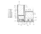
左面側の断熱壁12は、図3にも示すように、外板28と内板29との間に、板状に構成された断熱部材としての真空断熱パネル30を挟んで構成されている。この場合、外板28は断熱箱体11の外側壁面を構成し、内板29は断熱箱体11の内側壁面を構成している。外板28は、鋼板を部分的に曲げ加工されて、全体としてほぼ平板状に形成されている。
Next, among the heat insulating walls 12 to 16, the heat insulating walls 12 and 13 on the left and right side will be described, but the heat insulating walls 12 and 13 on the left and right side are substantially the same except that they are symmetrical. Therefore, the following description will be made with the left heat insulating wall 12 as a representative.
As shown in FIG. 3, the left-side heat insulating wall 12 is configured by sandwiching a vacuum heat insulating panel 30 as a heat insulating member formed in a plate shape between an outer plate 28 and an inner plate 29. In this case, the outer plate 28 constitutes the outer wall surface of the heat insulating box 11, and the inner plate 29 constitutes the inner wall surface of the heat insulating box 11. The outer plate 28 is formed in a substantially flat shape as a whole by bending a steel plate partially.

具体的には、外板28は、第一側面部281と、第二側面部282と、傾斜部283と、前面部284と、曲げ部285とから構成されている。第一側面部281と、第二側面部282と、傾斜部283とは、断熱箱体11の左側の外面を構成している。このうち第一側面部281は、ほぼ平坦に形成されて断熱箱体11の左側の外面の大部分を占めている。第二側面部282は、第一側面部281に対して、やや左外方であってほぼ平行に位置している。そして、これら第一側面部281および第二側面部282の間は傾斜部283によって繋がっている。   Specifically, the outer plate 28 includes a first side surface portion 281, a second side surface portion 282, an inclined portion 283, a front surface portion 284, and a bent portion 285. The first side surface portion 281, the second side surface portion 282, and the inclined portion 283 constitute the left outer surface of the heat insulating box 11. Among these, the 1st side part 281 is formed substantially flat and occupies most of the outer surface of the left side of the heat insulation box 11. FIG. The second side surface portion 282 is located slightly parallel to the left side and substantially parallel to the first side surface portion 281. The first side surface portion 281 and the second side surface portion 282 are connected by an inclined portion 283.

前面部284は、第二側面部282から繋がっており、第二側面部282に対してほぼ直角に内板29側つまり右方へ曲げられて、左面側の断熱壁12の前面を構成している。曲げ部285は、前面部284から繋がって、前面部284に対してほぼ直角に後方へ曲げられて第二側面部282にほぼ平行な面と、さらにそこからほぼ直角に内方つまり右方へ曲げられて前面部284にほぼ平行な面とから構成されている。そして、この外板28は、前後方向の断面つまり横断面が上下方向へほぼ同一形状に連続している。   The front surface portion 284 is connected to the second side surface portion 282, and is bent to the inner plate 29 side, that is, to the right substantially at a right angle to the second side surface portion 282 to constitute the front surface of the heat insulating wall 12 on the left surface side. Yes. The bent portion 285 is connected to the front surface portion 284 and is bent rearward at a substantially right angle with respect to the front surface portion 284 so as to be substantially parallel to the second side surface portion 282. It is composed of a surface that is bent and substantially parallel to the front surface portion 284. The outer plate 28 has a cross section in the front-rear direction, that is, a transverse cross section, which is continuous in the same shape in the vertical direction.

内板29は、例えばABS樹脂などの合成樹脂製の板で構成されて、全体としてほぼ平板状に形成されている。この場合、内板29に設けられる構造物、例えば図2に示す棚支持部31やガイド部32などは、別体にして内板29に取付ける構成としてもよいし、内板29と一体に形成してもよい。この内板29には、詳細は図示しないが、断熱仕切壁17、仕切板18、および横梁部材19が、直接的または間接的に取付けられている。例えば、内板29に対して、断熱仕切壁17、仕切板18、および横梁部材19をねじなどで直接固定したり、内板29に図示しない載置部を設けて、その載置部に断熱仕切壁17、仕切板18、横梁部材19を載置したりすればよい。   The inner plate 29 is made of, for example, a synthetic resin plate such as ABS resin, and is formed in a substantially flat plate shape as a whole. In this case, the structure provided on the inner plate 29, for example, the shelf support portion 31 and the guide portion 32 shown in FIG. 2, may be configured separately and attached to the inner plate 29, or formed integrally with the inner plate 29. May be. Although not shown in detail in the inner plate 29, the heat insulating partition wall 17, the partition plate 18, and the cross beam member 19 are directly or indirectly attached. For example, the heat insulating partition wall 17, the partition plate 18, and the cross beam member 19 are directly fixed to the inner plate 29 with screws or the like, or a mounting portion (not shown) is provided on the inner plate 29 to insulate the mounting portion. The partition wall 17, the partition plate 18, and the cross beam member 19 may be placed.

真空断熱パネル30は、図2に示すように、断熱壁12よりもやや小さい矩形状に形成されている。つまり、真空断熱パネル30は、外板28および内板29よりもやや小さい矩形状に形成されている。そして、真空断熱パネル30は、図3に示すように、液状の接着剤例えばホットメルトなどの熱可塑性の樹脂接着剤によって外板28および内板29に接着固定されている。   The vacuum heat insulation panel 30 is formed in the rectangular shape a little smaller than the heat insulation wall 12, as shown in FIG. That is, the vacuum heat insulation panel 30 is formed in a rectangular shape that is slightly smaller than the outer plate 28 and the inner plate 29. As shown in FIG. 3, the vacuum heat insulation panel 30 is bonded and fixed to the outer plate 28 and the inner plate 29 with a liquid adhesive, for example, a thermoplastic resin adhesive such as hot melt.

この場合、真空断熱パネル30の内板29側の面は、ほぼ全体に亘って内板29に接着固定されており、内板29の前端部は真空断熱パネル30の前端部よりも前方に位置している。また、真空断熱パネル30の外板28側の面は、第一側面部281に対向する面が接着固定されており、真空断熱パネル30と第二側面部282との間には隙間が形成されている。そして、外板28の前端部つまり前面部284および曲げ部285は、真空断熱パネル30の前端部つまり前端面303より前方に位置している。また、内板29の前端部も真空断熱パネル30の前端面303より前方に位置している。   In this case, the surface on the inner plate 29 side of the vacuum heat insulating panel 30 is bonded and fixed to the inner plate 29 almost entirely, and the front end portion of the inner plate 29 is positioned in front of the front end portion of the vacuum heat insulating panel 30. doing. Further, the surface on the outer plate 28 side of the vacuum heat insulating panel 30 is bonded and fixed to the surface facing the first side surface portion 281, and a gap is formed between the vacuum heat insulating panel 30 and the second side surface portion 282. ing. The front end portion, that is, the front surface portion 284 and the bent portion 285 of the outer plate 28 are located in front of the front end portion, that is, the front end surface 303 of the vacuum heat insulating panel 30. Further, the front end portion of the inner plate 29 is also positioned in front of the front end face 303 of the vacuum heat insulating panel 30.

ここで、真空断熱パネル30の構成について説明する。真空断熱パネル30は、基材301を袋体302に収容し、その内部を真空排気により減圧密封させて構成されている。基材301は、例えばグラスウールなどの無機繊維の積層材を型によって圧縮硬化させて板状に成型されたものである。袋体302は、ガスバリア性能を得るために、例えばアルミ蒸着層やアルミ箔層などの金属層を含んで構成されている。このように、真空断熱パネル30は、基材301をこの基材301よりも熱伝導率の高い袋体302に収容して構成されている。この場合、金属層に覆われた真空断熱パネル30の表面つまり袋体302は基材301よりも熱伝導率が高く熱を伝えやすいが、袋体302の内部を真空状態にして空気の熱伝導を抑えることで、真空断熱パネル30は全体として高い断熱性能を発揮している。   Here, the structure of the vacuum heat insulation panel 30 is demonstrated. The vacuum heat insulation panel 30 is configured by accommodating a base material 301 in a bag 302 and sealing the inside thereof under reduced pressure by vacuum evacuation. The base material 301 is formed into a plate shape by compressing and curing a laminated material of inorganic fibers such as glass wool with a mold. The bag body 302 includes a metal layer such as an aluminum vapor deposition layer or an aluminum foil layer in order to obtain gas barrier performance. Thus, the vacuum heat insulation panel 30 is configured by housing the base material 301 in the bag body 302 having a higher thermal conductivity than the base material 301. In this case, the surface of the vacuum heat insulation panel 30 covered with the metal layer, that is, the bag body 302 has a higher thermal conductivity than the base material 301 and is easy to transfer heat. By suppressing the above, the vacuum heat insulation panel 30 exhibits high heat insulation performance as a whole.

断熱壁12の前端縁部、つまり断熱箱体11の開口側に位置する断熱壁12の端縁部内には、外板28の第二側面部282の一部および前面部284と、内板29とによって、真空断熱パネル30の端縁部、即ち前端面303に面した収容部33が形成されている。また、外板28の前端部である曲げ部285および内板29の前端部が離間して設けられていることにより、収容部33を外部へ連通する連通口34が形成されている。   In the front end edge of the heat insulating wall 12, that is, in the end edge of the heat insulating wall 12 located on the opening side of the heat insulating box 11, a part of the second side surface portion 282 of the outer plate 28, the front surface portion 284, and the inner plate 29 Thus, an accommodating portion 33 facing the edge of the vacuum heat insulating panel 30, that is, the front end surface 303 is formed. Further, the bent portion 285 which is the front end portion of the outer plate 28 and the front end portion of the inner plate 29 are provided apart from each other, thereby forming a communication port 34 for communicating the housing portion 33 to the outside.

収容部33内には、補助部材35と、ソフトテープ361、362と、が設けられている。補助部材35は、外板28よりも厚い金属板、例えば鋼板で構成されており、外板28の前端部の内側面、つまり第二側面部282の前側部分と、前面部284と、曲げ部285における第二側面部282に平行な部分と、に沿って曲げられている。   An auxiliary member 35 and soft tapes 361 and 362 are provided in the accommodating portion 33. The auxiliary member 35 is made of a metal plate that is thicker than the outer plate 28, such as a steel plate, and has an inner surface at the front end of the outer plate 28, that is, a front portion of the second side surface portion 282, a front surface portion 284, and a bent portion. 285 is bent along a portion parallel to the second side surface portion 282.

ソフトテープ361、362は、例えばクロロプレンフォームなどの合成ゴムの発泡体で構成されており、柔軟性、伸縮性、断熱性、防水性に優れている。そのため、ソフトテープ361、362を収容部33内に設けることにより、収容部33内へ外気が流入することを防ぐとともに熱の移動を防いで、収容部33内の結露の防止を図っている。この場合、ソフトテープ361、362は、防露手段として機能している。   The soft tapes 361 and 362 are made of a synthetic rubber foam such as chloroprene foam, and are excellent in flexibility, stretchability, heat insulation, and waterproofness. Therefore, by providing the soft tapes 361 and 362 in the housing portion 33, the outside air is prevented from flowing into the housing portion 33 and the movement of heat is prevented, thereby preventing condensation in the housing portion 33. In this case, the soft tapes 361 and 362 function as dew prevention means.

ソフトテープ361、362は、詳細は図示しないが、それぞれ単体の状態において横断面がほぼ矩形状を成している。ソフトテープ361は、真空断熱パネル30の前端面303において露出部304を除いた部分に接着固定されている。これにより、真空断熱パネル30は、袋体302の一部、即ち露出部304における袋体302が収容部33内に露出している。また、ソフトテープ362は、補助部材35の内側面、即ち外板28とは反対側の面に接着固定されている。   Although the details of the soft tapes 361 and 362 are not shown, the cross sections of the soft tapes 361 and 362 are substantially rectangular in a single state. The soft tape 361 is bonded and fixed to a portion of the front end surface 303 of the vacuum heat insulating panel 30 excluding the exposed portion 304. Thereby, in the vacuum heat insulation panel 30, a part of the bag body 302, that is, the bag body 302 in the exposed portion 304 is exposed in the housing portion 33. The soft tape 362 is bonded and fixed to the inner side surface of the auxiliary member 35, that is, the surface opposite to the outer plate 28.

収容部33内において、ソフトテープ361およびソフトテープ362の間には、防露パイプ37と、この防露パイプ37を保持するシール部材38とが設けられている。防露パイプ37は、冷凍サイクルの圧縮機と冷却器とを繋ぐパイプの一部であり、例えば銅管で構成されている。防露パイプ37は、図2に示すように、冷蔵庫10の前面に形成された開口の周囲に沿って、複数の断熱壁この場合断熱壁12、13、14に亘って設けられている。この防露パイプ37には、圧縮機で圧縮されて高温状態となった冷媒が流される。すると、防露パイプ37は周囲に比べて高温状態となる。これにより冷蔵庫10内の冷気によって収容部33内および冷蔵庫10の開口部周辺が冷やされることを防ぎ、収容部33内および冷蔵庫10の開口部周辺の結露の防止を図っている。この場合、防露パイプ37は、防露手段として機能している。   In the housing portion 33, a dew-proof pipe 37 and a seal member 38 that holds the dew-proof pipe 37 are provided between the soft tape 361 and the soft tape 362. The dewproof pipe 37 is a part of a pipe that connects the compressor and the cooler of the refrigeration cycle, and is made of, for example, a copper pipe. As shown in FIG. 2, the dewproof pipe 37 is provided across a plurality of heat insulating walls, in this case, the heat insulating walls 12, 13, and 14, along the periphery of the opening formed in the front surface of the refrigerator 10. The dew-proof pipe 37 is supplied with a refrigerant that has been compressed by the compressor and brought to a high temperature state. Then, the dewproof pipe 37 is in a higher temperature state than the surroundings. Thereby, the inside of the accommodating part 33 and the periphery of the opening part of the refrigerator 10 are prevented from being cooled by the cold air in the refrigerator 10, and condensation in the accommodating part 33 and around the opening part of the refrigerator 10 is prevented. In this case, the dew proof pipe 37 functions as a dew proof means.

シール部材38は、防露パイプ37を保持するとともに、連通口34を閉塞して外板28および内板29を繋いでいる。この場合、シール部材38は閉塞手段として機能している。具体的には、シール部材38は、外板28側から内板29側へ向かって順に、パイプ保持部381、弾性変形部382、第一連結部383、第二連結部384、第一爪部385、第二爪部386、閉塞部387、第一係止部388、および第二係止部389を有し、これらが一体に形成されている。このシール部材38は、外板28よりも熱伝導率が低い材料、例えば合成樹脂や硬質ゴムなどを材料として引抜成形または押出成形により構成されている。そのため、シール部材38は、上下方向、即ち外板28および内板29の長手方向へほぼ同一の断面形状が連続する構成となっている。   The seal member 38 holds the dew-proof pipe 37 and closes the communication port 34 to connect the outer plate 28 and the inner plate 29. In this case, the seal member 38 functions as a closing means. Specifically, the seal member 38 includes, in order from the outer plate 28 side to the inner plate 29 side, a pipe holding portion 381, an elastic deformation portion 382, a first connecting portion 383, a second connecting portion 384, and a first claw portion. 385, a second claw portion 386, a closing portion 387, a first locking portion 388, and a second locking portion 389, which are integrally formed. The seal member 38 is formed by pultrusion molding or extrusion molding using a material having a lower thermal conductivity than the outer plate 28, for example, a synthetic resin or hard rubber. Therefore, the seal member 38 has a configuration in which substantially the same cross-sectional shape continues in the vertical direction, that is, in the longitudinal direction of the outer plate 28 and the inner plate 29.

シール部材38のパイプ保持部381は、図3における左側の一部分が開口した半円環状に形成されており、この半円環状の内側に防露パイプ37を咥えこむようにして保持している。この場合、連通口34は、シール部材38のパイプ保持部381および防露パイプ37に対して大きい寸法に設定されている。これにより、シール部材38のパイプ保持部381および防露パイプ37は連通口34から収容部33内へ挿入可能になっている。   The pipe holding portion 381 of the seal member 38 is formed in a semi-annular shape with an opening on the left side in FIG. 3 and holds the dew-proof pipe 37 inside the semi-annular shape. In this case, the communication port 34 is set to have a large size with respect to the pipe holding portion 381 and the dew proof pipe 37 of the seal member 38. As a result, the pipe holding portion 381 and the dew proof pipe 37 of the seal member 38 can be inserted into the accommodating portion 33 from the communication port 34.

収容部33内において、防露パイプ37の一部は、パイプ保持部381から露出して補助部材35に接触している。つまり、防露パイプ37は、補助部材35に直接接触しているとともに、外板28に対しても補助部材35を介して間接的に接触している。このため、防露パイプ37は、補助部材35と熱伝導可能であるとともに、外板28に対しても補助部材35を介して熱伝導可能である。   In the housing portion 33, a part of the dew proof pipe 37 is exposed from the pipe holding portion 381 and is in contact with the auxiliary member 35. That is, the dew proof pipe 37 is in direct contact with the auxiliary member 35 and is also indirectly in contact with the outer plate 28 via the auxiliary member 35. For this reason, the dew proof pipe 37 can conduct heat with the auxiliary member 35 and can also conduct heat with respect to the outer plate 28 via the auxiliary member 35.

弾性変形部382は、前方へやや膨出した湾曲状に形成されていて、その一方の端がパイプ保持部381における半円環状の開口の反対側に繋がっている。弾性変形部382は、湾曲状の頂点部を中心に、主に図3における左右方向、即ち真空断熱パネル30の厚み方向へ弾性変形して伸縮する。これにより、シール部材38は全体として真空断熱パネル30の厚み方向へ弾性変形して伸縮する。   The elastic deformation portion 382 is formed in a curved shape slightly bulging forward, and one end of the elastic deformation portion 382 is connected to the opposite side of the semicircular opening in the pipe holding portion 381. The elastically deforming portion 382 is elastically deformed and expanded mainly in the left-right direction in FIG. 3, that is, in the thickness direction of the vacuum heat insulating panel 30 with the curved apex portion as the center. Thereby, the sealing member 38 as a whole expands and contracts by elastically deforming in the thickness direction of the vacuum heat insulating panel 30.

弾性変形部382の他方の端は、内板29側へ向かうにつれて前後方向へ広がるように二股に分岐している。その分岐した一方には第一連結部383が設けられ、他方には第二連結部384が設けられている。第一連結部383は、主に第二連結部384との分岐部39を支点にして前後方向へ弾性変形する。第一連結部383の端部には第一爪部385が設けられて、この第一爪部385は内板29に係止している。また、第二連結部384の途中部には第二爪部386が設けられて、第二爪部386が補助部材35を介して外板28の曲げ部285に係止している。   The other end of the elastically deforming portion 382 is bifurcated so as to expand in the front-rear direction toward the inner plate 29 side. One of the branches is provided with a first connecting portion 383, and the other is provided with a second connecting portion 384. The first connecting portion 383 is elastically deformed in the front-rear direction mainly using the branch portion 39 with the second connecting portion 384 as a fulcrum. A first claw portion 385 is provided at an end of the first connecting portion 383, and the first claw portion 385 is locked to the inner plate 29. A second claw portion 386 is provided in the middle of the second connecting portion 384, and the second claw portion 386 is engaged with the bent portion 285 of the outer plate 28 via the auxiliary member 35.

閉塞部387は、第二連結部384から繋がって、内板29にほぼ平行に配置されて連通口34を覆っている。閉塞部387の後端部には、真空断熱パネル30の前端面303よりも後方に即ち真空断熱パネル30の側面領域内に位置して第一係止部388が設けられている。この第一係止部388と第一爪部385との間に内板29の前端部分を挟み込んで係合している。このため、シール部材38と内板29との境界部は、真空断熱パネル30の側面領域内に位置している。   The blocking portion 387 is connected to the second connecting portion 384 and is disposed substantially parallel to the inner plate 29 to cover the communication port 34. A first locking portion 388 is provided at the rear end portion of the closing portion 387, located behind the front end surface 303 of the vacuum heat insulation panel 30, that is, in the side surface region of the vacuum heat insulation panel 30. A front end portion of the inner plate 29 is sandwiched and engaged between the first locking portion 388 and the first claw portion 385. For this reason, the boundary between the sealing member 38 and the inner plate 29 is located in the side surface region of the vacuum heat insulating panel 30.

この場合、第一係止部388は、閉塞部387と一体的に、主に該閉塞部387および第二連結部384の接続部40を支点にして図3の左右方向つまり内板29の厚み方向へ弾性変形する。また、第一爪部385および第一係止部388間の左右方向の寸法は、内板29を挟み込んでいない状態において内板29の厚み寸法よりもやや小さく設定されている。そのため、第一爪部385および第一係止部388の間に内板29を係合した状態において、内板29には第一係止部388の弾性変形による復元力つまり保持力が作用する。これにより、内板29は、シール部材38の第一爪部385および第一係止部338の間にしっかりと固定されている。   In this case, the first locking portion 388 is integrated with the closing portion 387, mainly in the connecting portion 40 of the closing portion 387 and the second connecting portion 384, and the thickness of the inner plate 29 in FIG. Elastically deforms in the direction. The horizontal dimension between the first claw portion 385 and the first locking portion 388 is set slightly smaller than the thickness dimension of the inner plate 29 in a state where the inner plate 29 is not sandwiched. Therefore, in a state where the inner plate 29 is engaged between the first claw portion 385 and the first locking portion 388, a restoring force, that is, a holding force due to elastic deformation of the first locking portion 388 acts on the inner plate 29. . Accordingly, the inner plate 29 is firmly fixed between the first claw portion 385 and the first locking portion 338 of the seal member 38.

閉塞部387の前端部は、外板28側へほぼ直角に折り曲げられて外板28の前面側に延出している。その前面部41は外板28の前面部284とほぼ同一平面上に配置されて、さらにそこから真空断熱パネル30側へほぼ直角に折り曲げられて第二係止部389が設けられている。この第二係止部389と第二爪部386との間には外板28の曲げ部285および補助部材35を挟み込んで係合している。これにより、シール部材38は、真空断熱パネル30の前端面303と対向する位置、即ち真空断熱パネル30の厚み領域内において外板28および補助部材35に係合している。   The front end portion of the closing portion 387 is bent at a substantially right angle toward the outer plate 28 and extends to the front side of the outer plate 28. The front surface portion 41 is disposed on substantially the same plane as the front surface portion 284 of the outer plate 28, and is further bent at a substantially right angle from the front surface portion 284 toward the vacuum heat insulation panel 30 to provide a second locking portion 389. Between the second locking portion 389 and the second claw portion 386, the bent portion 285 of the outer plate 28 and the auxiliary member 35 are sandwiched and engaged. Thereby, the seal member 38 is engaged with the outer plate 28 and the auxiliary member 35 in a position facing the front end face 303 of the vacuum heat insulation panel 30, that is, in a thickness region of the vacuum heat insulation panel 30.

この場合、第二係止部389は、閉塞部387の前端部と一体に、主に接続部40を支点にして図3の左右方向つまり外板28の曲げ部285の厚み方向へ弾性変形する。また、第二爪部386および第二係止部389間の左右方向の寸法は、外板28および補助部材35の厚みを合わせた寸法よりもやや小さく設定されている。そのため、第二爪部386および第二係止部389の間に、外板28の曲げ部285および補助部材35を係合した状態において、これら曲げ部285および補助部材35には第二係止部389の弾性変形による復元力つまり保持力が作用する。これにより、シール部材38は、外板28に確実に固定されている。   In this case, the second locking portion 389 is elastically deformed integrally with the front end portion of the closing portion 387 mainly in the left-right direction of FIG. 3, that is, in the thickness direction of the bent portion 285 of the outer plate 28 with the connection portion 40 as a fulcrum. . The horizontal dimension between the second claw portion 386 and the second locking portion 389 is set to be slightly smaller than the total thickness of the outer plate 28 and the auxiliary member 35. Therefore, in a state where the bent portion 285 and the auxiliary member 35 of the outer plate 28 are engaged between the second claw portion 386 and the second locking portion 389, the bent portion 285 and the auxiliary member 35 are locked to the second locking portion. A restoring force, that is, a holding force due to elastic deformation of the portion 389 acts. Thereby, the seal member 38 is securely fixed to the outer plate 28.

また、シール部材38は、収容部33内に設けられた状態で、弾性変形部382がやや圧縮されるように設定されている。そのため、弾性変形部382の復元力によって、パイプ保持部381、第一爪部385、第二爪部386にそれぞれ押圧力が作用する。これにより、シール部材38が外板28および内板29にしっかりと固定される。さらに、防露パイプ37は、パイプ保持部381によって補助部材35に対してしっかりと押しつけられる。これにより、防露パイプ37の熱を、効率よく補助部材35を介して外板28に伝えることができる。   Further, the seal member 38 is set so that the elastic deformation portion 382 is slightly compressed in a state where the seal member 38 is provided in the accommodating portion 33. Therefore, a pressing force acts on each of the pipe holding portion 381, the first claw portion 385, and the second claw portion 386 by the restoring force of the elastic deformation portion 382. Thereby, the seal member 38 is firmly fixed to the outer plate 28 and the inner plate 29. Further, the dew proof pipe 37 is firmly pressed against the auxiliary member 35 by the pipe holding portion 381. Thereby, the heat of the dew proof pipe 37 can be efficiently transmitted to the outer plate 28 via the auxiliary member 35.

次に、断熱箱体11の開口前方に設けられた各断熱扉について、左側回転断熱扉22を代表させて説明する。
断熱扉22は、断熱性を有する扉本体42と、扉本体42の周囲の隙間からの熱漏洩を防ぐマグネットガスケット43とから構成されている。扉本体42は、冷蔵庫10の庫外側に位置する鋼板製の扉外板421および庫内側に位置する樹脂製の扉内板422の間に例えば発泡ウレタンなどの断熱材423を充填して構成されている。なお、断熱材として真空断熱パネルを用いてもよい。
Next, each heat insulation door provided in front of the opening of the heat insulation box 11 will be described using the left rotation heat insulation door 22 as a representative.
The heat insulating door 22 includes a door main body 42 having heat insulating properties and a magnet gasket 43 that prevents heat leakage from a gap around the door main body 42. The door main body 42 is configured by filling a heat insulating material 423 such as urethane foam between a steel plate door outer plate 421 positioned on the outer side of the refrigerator 10 and a resin door inner plate 422 positioned on the inner side of the refrigerator 10. ing. In addition, you may use a vacuum heat insulation panel as a heat insulating material.

マグネットガスケット43は、扉本体42の周縁部において扉内板422に取付けられている。このマグネットガスケット43は、例えば軟質樹脂を紐状に押出成形された柔軟なガスケット本体431の内部に、ラバーマグネット432を挿入して構成されている。マグネットガスケット43は、ラバーマグネット432が断熱壁12の外板28および補助部材35に吸着される。これにより、マグネットガスケット43と断熱壁12の外板28とが密着し、断熱箱体11の開口が断熱扉22で密閉される。
この場合、外板28とシール部材38の境界部はマグネットガスケット43によって覆われている。そのため、外板28とシール部材38の境界部から収容部33内へ外気または庫内の冷気が流入することを極力防ぐことができる。
The magnet gasket 43 is attached to the door inner plate 422 at the peripheral edge of the door main body 42. The magnet gasket 43 is configured by inserting a rubber magnet 432 into a flexible gasket main body 431 in which, for example, a soft resin is extruded in a string shape. In the magnet gasket 43, the rubber magnet 432 is attracted to the outer plate 28 and the auxiliary member 35 of the heat insulating wall 12. Thereby, the magnet gasket 43 and the outer plate 28 of the heat insulation wall 12 are brought into close contact with each other, and the opening of the heat insulation box 11 is sealed with the heat insulation door 22.
In this case, the boundary between the outer plate 28 and the sealing member 38 is covered with the magnet gasket 43. Therefore, it is possible to prevent as much as possible the outside air or the cool air in the cabinet from flowing into the accommodating portion 33 from the boundary portion between the outer plate 28 and the seal member 38.

次に、断熱壁12の組立手順について説明する。
まず、外板28の前面部284内側に補助部材35を配置して、これらをねじや接着剤などで固定する。さらに、ソフトテープ362を補助部材35の内側に接着剤や両面テープなどで固定する。これとは別に、ソフトテープ361を、真空断熱パネル30の前端面303において露出部304を除いた位置に接着剤や両面テープなどで固定し、この真空断熱パネル30の一方の面を外板28に対して接着固定する。この場合、外板28または真空断熱パネル30の少なくとも一方の側面に、液状の接着剤としてホットメルトなどの熱可塑性の樹脂製接着剤を塗布して外板28と真空断熱パネル30とを接着固定する。
Next, the assembly procedure of the heat insulation wall 12 will be described.
First, the auxiliary member 35 is disposed inside the front surface portion 284 of the outer plate 28, and these are fixed with screws, an adhesive, or the like. Further, the soft tape 362 is fixed inside the auxiliary member 35 with an adhesive or a double-sided tape. Separately, the soft tape 361 is fixed to the front end surface 303 of the vacuum heat insulation panel 30 at a position excluding the exposed portion 304 with an adhesive or double-sided tape, and one surface of the vacuum heat insulation panel 30 is fixed to the outer plate 28. Adhere to and fix. In this case, a thermoplastic resin adhesive such as hot melt is applied as a liquid adhesive to at least one side surface of the outer plate 28 or the vacuum heat insulating panel 30 to bond and fix the outer plate 28 and the vacuum heat insulating panel 30 together. To do.

そして、内板29を真空断熱パネル30の他方の面に対して接着固定する。この場合も、内板29または真空断熱パネル30の少なくとも一方の側面に、液状の接着剤としてホットメルトなどの樹脂製接着剤を塗布して内板29と真空断熱パネル30とを接着固定する。これにより、断熱壁12の前端部には、真空断熱パネル30の前端縁部の近傍に収容部33が形成されるとともに、収容部33と外部とを連通する連通口34が形成される。   Then, the inner plate 29 is bonded and fixed to the other surface of the vacuum heat insulating panel 30. Also in this case, a resin adhesive such as hot melt is applied as a liquid adhesive to at least one side surface of the inner plate 29 or the vacuum heat insulation panel 30 to bond and fix the inner plate 29 and the vacuum heat insulation panel 30 together. Thereby, at the front end portion of the heat insulating wall 12, a housing portion 33 is formed in the vicinity of the front end edge portion of the vacuum heat insulating panel 30, and a communication port 34 that connects the housing portion 33 and the outside is formed.

このとき、断熱壁12は、接着剤が硬化せずに必要な強度が得られていない状態で断熱箱体11として組み立てられると、例えば左右の断熱壁12、13を支持する断熱仕切壁17や横梁部材19などから応力を受けて、内板29および外板28と、真空断熱パネル30との接着が剥がれてしまうおそれがある。そのため、断熱壁12は、外板28および内板29と、真空断熱パネル30とが接着された後、接着剤が硬化して必要な強度が得られるまでの一定時間は断熱箱体11として組立てられることなく静置保管される。   At this time, when the heat insulating wall 12 is assembled as the heat insulating box 11 in a state where the adhesive is not cured and the necessary strength is not obtained, for example, the heat insulating partition walls 17 that support the left and right heat insulating walls 12 and 13 There is a risk that adhesion between the inner plate 29 and the outer plate 28 and the vacuum heat insulation panel 30 may be peeled off due to stress from the cross beam member 19 or the like. Therefore, the heat insulating wall 12 is assembled as the heat insulating box 11 for a certain time after the outer plate 28 and the inner plate 29 and the vacuum heat insulating panel 30 are bonded to each other until the required strength is obtained by curing the adhesive. It is kept stationary without being done.

この場合、断熱壁12は、防露パイプ37およびシール部材38が収容部33内に収容されていない状態で、接着剤が硬化するまで静置保管される。そして防露パイプ37は、断熱壁12が他の断熱壁13〜16とともに断熱箱体11として組立てられた後に断熱壁12内に挿入される。これは、防露パイプ37は、図2に示すように各断熱壁12〜16に跨って設けられるからである。つまり、各断熱壁12〜16に防露パイプ37を取付けた後に断熱箱体11として組み立てることは、防露パイプ37を引き回す作業が増えることになり、作業効率の低下を招くことになるからである。   In this case, the heat insulating wall 12 is stored stationary until the adhesive is cured in a state where the dew proof pipe 37 and the seal member 38 are not housed in the housing portion 33. The dew-proof pipe 37 is inserted into the heat insulating wall 12 after the heat insulating wall 12 is assembled as the heat insulating box 11 together with the other heat insulating walls 13 to 16. This is because the dew-proof pipe 37 is provided across the heat insulating walls 12 to 16 as shown in FIG. That is, assembling as the heat insulation box 11 after attaching the dew prevention pipe 37 to each of the heat insulation walls 12 to 16 increases the work of drawing the dew prevention pipe 37, leading to a decrease in work efficiency. is there.

また、外板28および内板29と真空断熱パネル30との剥がれを防ぐため、断熱壁12には、接着剤が充分に硬化するまではできるだけ力が働かないことが望ましい。本実施形態の場合、断熱壁12はほぼ平坦な平板状に構成されている。そのため、複数の断熱壁12を重ねて保管する場合であっても、断熱壁12は、重ねられた他の断熱壁の凹凸部から力を受けることが少ない。したがって、断熱壁12は、接着剤を硬化させるための保管中において力が作用することを極力防がれるため、外板28および内板29と真空断熱パネル30とが剥がれることを極力防ぐことができる。   Further, in order to prevent the outer plate 28 and the inner plate 29 and the vacuum heat insulation panel 30 from being peeled off, it is desirable that as little force as possible acts on the heat insulation wall 12 until the adhesive is sufficiently cured. In the case of this embodiment, the heat insulation wall 12 is comprised by the substantially flat flat plate shape. Therefore, even when a plurality of heat insulating walls 12 are stacked and stored, the heat insulating walls 12 are less likely to receive force from the uneven portions of other stacked heat insulating walls. Therefore, the heat insulating wall 12 prevents the outer plate 28, the inner plate 29, and the vacuum heat insulating panel 30 from being peeled off as much as possible because it prevents the force from acting during storage for curing the adhesive. it can.

また、このような静置保管が必要となる接着部分は、できるだけ短時間で硬化させることが望ましい。硬化時間が長くなると、断熱壁の製造時間が長くなるため、静置保管を行う断熱壁の数が増える。そのため、より広い保管場所が必要となることから、効率的な製造の妨げとなり、ひいては製造コストの増加に繋がるからである。   In addition, it is desirable that such an adhesive part that needs to be kept stationary is cured in as short a time as possible. If the curing time is increased, the manufacturing time of the heat insulating wall is increased, so that the number of heat insulating walls to be kept stationary increases. For this reason, a wider storage space is required, which hinders efficient production and leads to an increase in production cost.

ここで、一般にホットメルトなど熱可塑性の樹脂製接着剤は冷却によって硬化するため、その硬化時間は接着部分の温度環境つまり冷却温度に影響される。例えば、真空断熱パネル30の周囲を外板28および内板29で完全に覆ってしまうと、真空断熱パネル30の周囲に熱がこもって接着部分が冷却されにくくなり、その結果、接着剤の硬化時間が長くなってしまう。本実施形態では、断熱壁12の内部つまり真空断熱パネル30が配置されている空間は連通口34を介して外部に連通している。このため、断熱壁12の内部に外気を取り入れて、外板28および内板29と、真空断熱パネル30との接着部分の冷却を促進し、これにより硬化時間の短縮が図られている。   Here, since the thermoplastic resin adhesive such as hot melt is generally cured by cooling, the curing time is affected by the temperature environment of the bonded portion, that is, the cooling temperature. For example, if the periphery of the vacuum heat insulation panel 30 is completely covered with the outer plate 28 and the inner plate 29, heat is trapped around the vacuum heat insulation panel 30, making it difficult for the bonded portion to be cooled. As a result, the adhesive is cured. The time will be longer. In the present embodiment, the inside of the heat insulating wall 12, that is, the space in which the vacuum heat insulating panel 30 is arranged communicates with the outside through the communication port 34. For this reason, outside air is taken into the inside of the heat insulation wall 12, and the cooling of the adhesion part of the outer plate 28, the inner plate 29, and the vacuum heat insulation panel 30 is accelerated | stimulated, and, thereby, shortening of hardening time is achieved.

断熱壁12は、接着剤が硬化して充分な強度が得られた後、他の断熱壁13〜16とともに箱体に組立てられる。そして、断熱壁12には防露パイプ37およびシール部材38が取付けられる。この場合、防露パイプ37は、シール部材38のパイプ保持部381に保持された状態で、連通口34から収容部33内へ挿入される。そして、ソフトテープ361、362を押し分けて所定位置に配置される。   The heat insulating wall 12 is assembled into a box together with the other heat insulating walls 13 to 16 after the adhesive is cured and sufficient strength is obtained. A dew proof pipe 37 and a seal member 38 are attached to the heat insulation wall 12. In this case, the dew proof pipe 37 is inserted into the accommodating portion 33 from the communication port 34 while being held by the pipe holding portion 381 of the seal member 38. Then, the soft tapes 361 and 362 are pushed and arranged at predetermined positions.

なお、ソフトテープ361、362は、柔軟性に富んでいるため、連通口34から収容部33内へ容易に挿入することができる。このため、ソフトテープ361、362の取付けは、収容部33内に防露パイプ37およびシール部材38が挿入される前であれば、断熱壁12を箱体として組み立てる前後どちらでもよい。   Since the soft tapes 361 and 362 are rich in flexibility, the soft tapes 361 and 362 can be easily inserted into the accommodating portion 33 from the communication port 34. For this reason, the soft tapes 361 and 362 may be attached either before or after the heat insulating wall 12 is assembled as a box as long as the dew proof pipe 37 and the seal member 38 are inserted into the housing portion 33.

ちなみに、シール部材38は、第一爪部385および第二爪部386間の幅つまり第一爪部385および第二爪部386の間における前後方向の寸法が、連通口34の開口幅つまり連通口34の前後方向の寸法よりも大きく設定されている。シール部材38は、連通口34から挿入される際に、第一連結部383が内板29から力を受けて分岐部39を支点に連通口34の開口幅方向つまり前後方向へ弾性変形する。これによりシール部材38における第一爪部385および第二爪部386間の幅は、連通口34の開口幅よりも小さくなり、シール部材38は、連通口34を通って収容部33内へ挿入される。   Incidentally, the seal member 38 has a width between the first claw portion 385 and the second claw portion 386, that is, a dimension in the front-rear direction between the first claw portion 385 and the second claw portion 386, so that the opening width of the communication port 34, that is, the communication width. It is set larger than the dimension of the mouth 34 in the front-rear direction. When the seal member 38 is inserted from the communication port 34, the first connection portion 383 receives a force from the inner plate 29 and elastically deforms in the opening width direction of the communication port 34, that is, the front-rear direction, with the branch portion 39 as a fulcrum. As a result, the width between the first claw portion 385 and the second claw portion 386 in the seal member 38 becomes smaller than the opening width of the communication port 34, and the seal member 38 is inserted into the housing portion 33 through the communication port 34. Is done.

また、シール部材38は、第一爪部385および第二爪部386が連通口34を通過して収容部33内まで挿入されると、第一連結部383の弾性変形が戻って第一爪部385が内板29に係止するとともに、第二爪部386も補助部材35を介して外板28に係止する。この場合、第一爪部385および第二爪部386間の幅は、連通口34の開口幅よりも大きい状態に戻っている。このため、シール部材38は、一旦収容部33内へ挿入された後は、容易に外れ難い構成となっている。   In addition, when the first claw portion 385 and the second claw portion 386 pass through the communication port 34 and are inserted into the housing portion 33, the elastic deformation of the first connecting portion 383 returns and the seal member 38 returns to the first claw. The portion 385 is locked to the inner plate 29, and the second claw portion 386 is also locked to the outer plate 28 via the auxiliary member 35. In this case, the width between the first claw portion 385 and the second claw portion 386 has returned to a state where it is larger than the opening width of the communication port 34. For this reason, the seal member 38 has a configuration that is not easily removed after being inserted into the housing portion 33 once.

上記した第一実施形態によれば次のような作用効果を得ることができる。
本実施形態の構成によれば、断熱箱体11を構成する左右両側の断熱壁12、13は、板状に構成された真空断熱パネル30を、外板28および内板29で挟んで構成されている。そして、この断熱壁12、13には、断熱箱体11の開口側に位置し真空断熱パネル30の前端面303の近傍に収容部33が形成されている。収容部33は、外板28および内板29で形成される連通口34によって外部へ連通している。収容部33にはソフトテープ361、362、および防露パイプ37が収容され、連通口34はシール部材38によって閉塞されている。
According to the first embodiment described above, the following operational effects can be obtained.
According to the configuration of the present embodiment, the left and right heat insulating walls 12 and 13 constituting the heat insulating box 11 are configured by sandwiching the vacuum heat insulating panel 30 configured in a plate shape between the outer plate 28 and the inner plate 29. ing. In the heat insulating walls 12 and 13, a housing portion 33 is formed in the vicinity of the front end surface 303 of the vacuum heat insulating panel 30 located on the opening side of the heat insulating box 11. The accommodating portion 33 communicates with the outside through a communication port 34 formed by the outer plate 28 and the inner plate 29. The accommodating portion 33 accommodates soft tapes 361 and 362 and a dew proof pipe 37, and the communication port 34 is closed by a seal member 38.

この構成によれば、ソフトテープ361、362、および防露パイプ37は、連通口34から挿入され、連通口34はシール部材38によって閉塞される。このため、左右両側の断熱壁12、13で断熱箱体11を形成した後に、これら断熱壁12、13内にソフトテープ361、362、および防露パイプ37を取付けることができる。そのため、防露パイプ37などを不要に引き回すことが避けられ、組立作業性の向上が図られる。   According to this configuration, the soft tapes 361 and 362 and the dew proof pipe 37 are inserted from the communication port 34, and the communication port 34 is closed by the seal member 38. For this reason, after forming the heat insulation box 11 by the heat insulation walls 12 and 13 of both right and left sides, the soft tapes 361 and 362 and the dew prevention pipe 37 can be attached in these heat insulation walls 12 and 13. Therefore, it is possible to avoid unnecessarily routing the dewproof pipe 37 and the like, and to improve the assembly workability.

また、真空断熱パネル30は、外板28および内板29に対して液状の接着剤例えばホットメルトなど熱可塑性の接着剤を硬化させて接着固定されている。この場合、真空断熱パネル30の貼付け位置は、接着剤が冷却されて粘性が無くなるまでに確定すればよいため、貼り直しが出来ない両面テープなどの粘着テープに比べて作業がし易い。   The vacuum heat insulating panel 30 is bonded and fixed to the outer plate 28 and the inner plate 29 by curing a liquid adhesive, for example, a thermoplastic adhesive such as hot melt. In this case, the application position of the vacuum heat insulating panel 30 may be determined before the adhesive is cooled and the viscosity disappears, and therefore, the work is easier to perform than an adhesive tape such as a double-sided tape that cannot be applied again.

さらに、真空断熱パネル30は、基材301を、金属層を含んで構成された熱伝導率の高い袋体302に収容して構成されている。そしてこの袋体302の一部は、露出部304として収容部33内に露出している。この場合、露出部304には、連通口34から取込まれた外気が直接接触している。このため、外板28および内板29と、真空断熱パネル30との接着部分の熱は、熱伝導率の大きい袋体302の表面を伝わって露出部304から放熱される。これにより、接着部分全体が効率よく冷却されて、硬化時間の短縮がより効果的に図られている。   Furthermore, the vacuum heat insulation panel 30 is configured by housing the base material 301 in a bag body 302 having a high thermal conductivity and including a metal layer. A part of the bag 302 is exposed as an exposed portion 304 in the accommodating portion 33. In this case, outside air taken in from the communication port 34 is in direct contact with the exposed portion 304. For this reason, the heat of the bonding portion between the outer plate 28 and the inner plate 29 and the vacuum heat insulation panel 30 is transmitted from the exposed portion 304 through the surface of the bag 302 having a high thermal conductivity. Thereby, the whole adhesion | attachment part is cooled efficiently and shortening of hardening time is aimed at more effectively.

また、外板28の前面部284および曲げ部285は、真空断熱パネル30の前端面303より前方に位置し、内板29の前端部も真空断熱パネル30の前端面303より前方に位置している。このため、外板28および内板29と、真空断熱パネル30とを接着する際に、外板28や内板29の端部によって真空断熱パネル30の袋体302が傷けられることを防ぐことができる。   Further, the front portion 284 and the bent portion 285 of the outer plate 28 are located in front of the front end face 303 of the vacuum heat insulating panel 30, and the front end portion of the inner plate 29 is also located in front of the front end face 303 of the vacuum heat insulating panel 30. Yes. For this reason, when the outer plate 28 and the inner plate 29 are bonded to the vacuum heat insulating panel 30, the bag 302 of the vacuum heat insulating panel 30 is prevented from being damaged by the end portions of the outer plate 28 and the inner plate 29. Can do.

また、収容部33には断熱性を有するソフトテープ361、362が収容されて、収容部33内を埋めている。これによれば、外気の流入を防いで収容部33内の結露の防止を図るとともに、真空断熱パネル30の存しない収容部33を介して庫内の冷気が外部へ漏れることを極力防ぐことができる。   The accommodating portion 33 accommodates heat-insulating soft tapes 361 and 362 to fill the accommodating portion 33. According to this, while preventing the inflow of external air and preventing condensation in the accommodating part 33, it is possible to prevent the cold air in the warehouse from leaking outside as much as possible through the accommodating part 33 where the vacuum heat insulating panel 30 does not exist. it can.

さらに、収容部33には、防露パイプ37が収容されている。これによれば、防露パイプ37を流れる冷媒の熱によって収容部33内が温められるため、庫内の冷気による結露を防止することができる。   Furthermore, a dew proof pipe 37 is accommodated in the accommodating portion 33. According to this, since the inside of the accommodating part 33 is warmed by the heat of the refrigerant flowing through the dew prevention pipe 37, it is possible to prevent dew condensation due to the cool air in the warehouse.

また、防露パイプ37は、外板28に対して熱伝導可能に接触している。これによれば、防露パイプ37の熱によって外板28が温められる。そのため、外板28のうち特には庫内側に近い前面部284や曲げ部285の周辺に生じる結露を効果的に防ぐことができる。   Further, the dewproof pipe 37 is in contact with the outer plate 28 so as to be able to conduct heat. According to this, the outer plate 28 is warmed by the heat of the dew proof pipe 37. Therefore, it is possible to effectively prevent the dew condensation that occurs around the front portion 284 and the bent portion 285 of the outer plate 28 particularly near the inside of the cabinet.

さらに、外板28には、前面部284の内側に沿って外板28よりも厚い金属板で構成された補助部材35が設けられている。そして、防露パイプ37の熱は、補助部材35を介して外板28に伝わる。これによれば、補助部材35は、断熱壁12の前端部を補強するとともに、防露パイプ37と外板28との熱伝導を阻害することがない。   Further, the outer plate 28 is provided with an auxiliary member 35 made of a metal plate thicker than the outer plate 28 along the inside of the front surface portion 284. The heat of the dew proof pipe 37 is transmitted to the outer plate 28 through the auxiliary member 35. According to this, the auxiliary member 35 reinforces the front end portion of the heat insulating wall 12 and does not hinder heat conduction between the dew proof pipe 37 and the outer plate 28.

また、連通口34は、外板28の前端部つまり曲げ部285と内板29の前端部との間に形成されている。そして、シール部材38は、連通口34を閉塞して外板28および内板29を繋いでいる。これによれば、断熱壁12、13を箱体に組立てた後に、防露パイプ37やソフトテープ361、362を、連通口34から収容部33内へ挿入することができる。また、外板28および内板29は、直接接続する形態ではないため、外板28および内板29と、真空断熱パネル30とを接着する際に、外板28および内板29が干渉することがない。そのため、作業が容易になる。   The communication port 34 is formed between the front end portion of the outer plate 28, that is, the bent portion 285 and the front end portion of the inner plate 29. The seal member 38 closes the communication port 34 and connects the outer plate 28 and the inner plate 29. According to this, after assembling the heat insulating walls 12 and 13 into the box, the dew-proof pipe 37 and the soft tapes 361 and 362 can be inserted into the accommodating portion 33 from the communication port 34. Further, since the outer plate 28 and the inner plate 29 are not directly connected, the outer plate 28 and the inner plate 29 interfere when the outer plate 28 and the inner plate 29 are bonded to the vacuum heat insulating panel 30. There is no. Therefore, work becomes easy.

また、シール部材38は、外板28よりも熱伝導率が低い合成樹脂や硬質ゴムなどから構成されて、前端部が外板28の前面側に延出して設けられている。これによれば、熱を伝え易い外板28が、庫内の冷気に直接接触して冷やされることによる結露を極力防ぐことができる。   The seal member 38 is made of a synthetic resin or hard rubber having a lower thermal conductivity than the outer plate 28 and has a front end portion extending to the front side of the outer plate 28. According to this, it is possible to prevent as much as possible dew condensation due to the outer plate 28 that easily transfers heat being cooled by being in direct contact with the cool air in the cabinet.

さらに、シール部材38は防露パイプ37を保持するパイプ保持部381を有している。そして防露パイプ37は、パイプ保持部381に保持された状態で収容部33内へ挿入される。これによれば、収容部33内において容易に防露パイプ37の位置を決めることができるとともに、防露パイプ37を容易に収容部33内へ挿入することができる。   Further, the seal member 38 has a pipe holding portion 381 that holds the dew proof pipe 37. The dew-proof pipe 37 is inserted into the accommodating portion 33 while being held by the pipe holding portion 381. According to this, the position of the dew proof pipe 37 can be easily determined in the housing portion 33, and the dew proof pipe 37 can be easily inserted into the housing portion 33.

また、シール部材38および内板29の境界部は、真空断熱パネル30の側面領域内に位置している。そのため、断熱壁12の前後方向において真空断熱パネル30が存しない部分、つまり収容部33の領域における庫内からの熱漏洩を極力防ぐことができる。   Further, the boundary between the seal member 38 and the inner plate 29 is located in the side region of the vacuum heat insulation panel 30. Therefore, it is possible to prevent heat leakage from the inside of the portion where the vacuum heat insulation panel 30 does not exist in the front-rear direction of the heat insulation wall 12, that is, the region of the accommodation portion 33 as much as possible.

ちなみに、真空断熱パネル30は、グラスウールなどを圧縮硬化させて板状の基材301を得ている。このため、真空断熱パネル30は、その厚み方向に対して最大2mm程度のばらつきが生じてしまう。本実施形態において、シール部材38は、弾性変形部382によって真空断熱パネル30の厚み方向へ弾性変形する。これにより、真空断熱パネル30のばらつきを吸収することができる。なお、左右方向の寸法が異なる複数種類のシール部材38を準備し、真空断熱パネル30の厚み方向のばらつきに対応させて選択する構成としてもよい。   Incidentally, the vacuum heat insulation panel 30 obtains a plate-like base material 301 by compressing and curing glass wool or the like. For this reason, the vacuum heat insulation panel 30 has a variation of about 2 mm at the maximum in the thickness direction. In the present embodiment, the seal member 38 is elastically deformed in the thickness direction of the vacuum heat insulating panel 30 by the elastic deformation portion 382. Thereby, the dispersion | variation in the vacuum heat insulation panel 30 can be absorbed. In addition, it is good also as a structure which prepares the multiple types of sealing member 38 from which the dimension of the left-right direction differs, and selects it corresponding to the dispersion | variation in the thickness direction of the vacuum heat insulation panel 30. FIG.

また、シール部材38は、第一係止部388と第一爪部385との間に内板29を係合し、第二係止部389と第二爪部386との間に外板28を係合している。これによれば、シール部材38は、外板28および内板29に対して確実と固定することができる。さらに、外板28および内板29は、シール部材38によって繋がれるため、断熱壁12の全体としての強度が増す。   The sealing member 38 engages the inner plate 29 between the first locking portion 388 and the first claw portion 385, and the outer plate 28 between the second locking portion 389 and the second claw portion 386. Is engaged. According to this, the seal member 38 can be reliably fixed to the outer plate 28 and the inner plate 29. Furthermore, since the outer plate 28 and the inner plate 29 are connected by the seal member 38, the strength of the heat insulating wall 12 as a whole increases.

さらに、外板28とシール部材38の境界部はマグネットガスケット43によって覆われている。これにより、外板28とシール部材38の境界部から収容部33内へ外気または庫内の冷気が流入することを極力防ぐことができる。   Further, the boundary between the outer plate 28 and the seal member 38 is covered with a magnet gasket 43. Thereby, it is possible to prevent as much as possible the outside air or the cool air in the cabinet from flowing into the housing portion 33 from the boundary portion between the outer plate 28 and the seal member 38.

(第二実施形態)
次に、第二実施形態について図4を参照して説明する。
この第二実施形態では、主にシール部材44の構成が上記第一実施形態と異なっている点で第一実施形態と異なる。具体的には、外板45は、第一実施形態と同様に鋼板を曲げて全体として平板状に構成されている。外板45の前端部には、前面部451と、前面部451から断熱壁12の内方へ巻き込むようにして曲げられた曲げ部452が形成されている。内板46は、ABS樹脂などから全体として平板状に構成されて、その前端部に内板係止部461が設けられている。これら外板45と内板46とによって収容部47が形成されている。そしてこの収容部47には、真空断熱パネル30の前端面303に接着されたソフトテープ36と、二本の防露パイプ37と、シール部材44が収容されている。
(Second embodiment)
Next, a second embodiment will be described with reference to FIG.
This second embodiment differs from the first embodiment mainly in that the configuration of the seal member 44 is different from the first embodiment. Specifically, the outer plate 45 is formed in a flat plate shape as a whole by bending a steel plate as in the first embodiment. A front end portion of the outer plate 45 is formed with a front portion 451 and a bent portion 452 bent so as to be wound inwardly of the heat insulating wall 12 from the front portion 451. The inner plate 46 is formed in a flat plate shape as a whole from ABS resin or the like, and an inner plate locking portion 461 is provided at the front end portion thereof. A housing portion 47 is formed by the outer plate 45 and the inner plate 46. The accommodating portion 47 accommodates a soft tape 36 bonded to the front end face 303 of the vacuum heat insulating panel 30, two dew-proof pipes 37, and a seal member 44.

シール部材44は、二個のパイプ保持部441、弾性変形部442、第一爪部443、第二爪部444、第一係止部445、第二係止部446、および閉塞部447から構成されている。このシール部材44は、第一実施形態と同様に合成樹脂などで構成されている。パイプ保持部441には防露パイプ37が保持されている。弾性変形部442は円弧状に形成されて、主に真空断熱パネル30の厚み方向へ弾性変形する。これにより、防露パイプ37を外板45に押し当てて熱伝導可能に接触させるとともに、真空断熱パネル30の厚み領域内において第二爪部444と第二係止部446との間に外板45の曲げ部452を係合している。   The seal member 44 includes two pipe holding portions 441, an elastic deformation portion 442, a first claw portion 443, a second claw portion 444, a first locking portion 445, a second locking portion 446, and a closing portion 447. Has been. The seal member 44 is made of synthetic resin or the like as in the first embodiment. The pipe holder 441 holds the dew proof pipe 37. The elastic deformation portion 442 is formed in an arc shape and elastically deforms mainly in the thickness direction of the vacuum heat insulating panel 30. Accordingly, the dew proof pipe 37 is pressed against the outer plate 45 so as to be able to conduct heat, and the outer plate is interposed between the second claw portion 444 and the second locking portion 446 in the thickness region of the vacuum heat insulating panel 30. 45 bent portions 452 are engaged.

また、シール部材44の第一爪部443と第一係止部445との間には内板46が係合されている。この場合、シール部材44の第一爪部443は、内板係止部461に係止されている。これにより真空断熱パネル30の露出部304が確保されている。また、第一実施形態と同様に、内板46には第一係止部445の弾性変形による復元力つまり保持力が作用する。これにより、内板29は、シール部材44の第一爪部443および第一係止部445の間にしっかりと固定されている。   The inner plate 46 is engaged between the first claw portion 443 and the first locking portion 445 of the seal member 44. In this case, the first claw portion 443 of the seal member 44 is locked to the inner plate locking portion 461. Thereby, the exposed portion 304 of the vacuum heat insulation panel 30 is secured. Similarly to the first embodiment, a restoring force, that is, a holding force due to elastic deformation of the first locking portion 445 acts on the inner plate 46. Accordingly, the inner plate 29 is firmly fixed between the first claw portion 443 and the first locking portion 445 of the seal member 44.

なお、シール部材44と外板45との境界部は、真空断熱パネル30の厚み領域に位置して図3に示すマグネットガスケット43によって覆われている。そして、シール部材44と内板46との境界部は、真空断熱パネル30の側面領域内に位置している。   The boundary between the seal member 44 and the outer plate 45 is located in the thickness region of the vacuum heat insulation panel 30 and is covered with the magnet gasket 43 shown in FIG. The boundary between the seal member 44 and the inner plate 46 is located in the side surface region of the vacuum heat insulating panel 30.

このような第二実施形態によれば、上記第一実施形態と同様の作用効果が得られる。さらに、外板45の曲げ部452は、断熱壁12の内方へ巻き込むようにして曲げて形成されている。これによれば、外板45の前端部の強度が増すことから、補強部材を不要とすることができる。   According to such 2nd embodiment, the effect similar to said 1st embodiment is acquired. Further, the bent portion 452 of the outer plate 45 is formed by being bent so as to be wound inward of the heat insulating wall 12. According to this, since the strength of the front end portion of the outer plate 45 increases, a reinforcing member can be made unnecessary.

(第三実施形態)
次に、第三実施形態について図5を参照して説明する。
この第三実施形態においても、主にシール部材48の構成が上記各実施形態と異なっている点で上記各実施形態と異なる。具体的には、外板49も鋼板により全体として平板状に構成されている。外板49の前端部には、外板49を折り畳むようにしてシール部材受部491が形成されている。また、内板50も、ABS樹脂などにより全体として平板状に構成されている。外板49および内板50によって形成される収容部51内には、ソフトテープ36および防露パイプ37が収容されている。
(Third embodiment)
Next, a third embodiment will be described with reference to FIG.
This third embodiment also differs from the above embodiments in that the configuration of the seal member 48 is mainly different from the above embodiments. Specifically, the outer plate 49 is also made of a steel plate in a flat plate shape as a whole. A seal member receiving portion 491 is formed at the front end portion of the outer plate 49 so that the outer plate 49 is folded. Further, the inner plate 50 is also configured as a flat plate as a whole by ABS resin or the like. A soft tape 36 and a dew proof pipe 37 are accommodated in the accommodating portion 51 formed by the outer plate 49 and the inner plate 50.

シール部材48は、閉塞部481、係合突部482、および内板受部483から構成されている。シール部材48は、係合突部482を外板49のシール部材受部491に挿入するとともに、内板受部483に内板50が挿入される。これにより、シール部材48は、連通口34を覆って、外板49および内板50に固定される。この場合、シール部材48の係合突部482は、外板49のシール部材受部491に対する挿入深さが変更可能になっている。このため、シール部材48は、真空断熱パネル30の厚み方向のばらつきに対応することができる。   The seal member 48 includes a closing portion 481, an engaging protrusion 482, and an inner plate receiving portion 483. In the seal member 48, the engaging protrusion 482 is inserted into the seal member receiving portion 491 of the outer plate 49, and the inner plate 50 is inserted into the inner plate receiving portion 483. Thereby, the seal member 48 covers the communication port 34 and is fixed to the outer plate 49 and the inner plate 50. In this case, the insertion depth of the engagement protrusion 482 of the seal member 48 with respect to the seal member receiving portion 491 of the outer plate 49 can be changed. For this reason, the seal member 48 can cope with variations in the thickness direction of the vacuum heat insulation panel 30.

なお、シール部材48と外板49との境界部は、真空断熱パネル30の厚み領域に位置して図3に示すマグネットガスケット43によって覆われている。そして、シール部材48と内板50との境界部は、真空断熱パネル30の側面領域内に位置している。
この第三実施形態によれば、上記各実施形態と同様の作用効果を得ることができる。
The boundary between the seal member 48 and the outer plate 49 is located in the thickness region of the vacuum heat insulation panel 30 and is covered with a magnet gasket 43 shown in FIG. The boundary between the sealing member 48 and the inner plate 50 is located in the side surface region of the vacuum heat insulating panel 30.
According to this 3rd embodiment, the same operation effect as each above-mentioned embodiment can be acquired.

(第四実施形態)
次に、第四実施形態について図6を参照して説明する。
第四実施形態において、シール部材52は、真空断熱パネル30の厚み寸法よりも幅広に構成されて、外板53および内板54の前端部を覆っている。具体的には、外板53は、上記各実施形態と同様に鋼板により全体として平板状に構成されており、この外板53の前端部には、外板53を断熱壁12内方へ折り曲げた返し部531が形成されている。また、内板54は、樹脂などにより全体として平板状に構成されている。外板53および内板54によって形成される収容部55内には、ソフトテープ36、および二本の防露パイプ371、372のうち一本の防露パイプ371が収容されている。また、外板53の返し部531および内板54の前端部の間には、収容部55を外部へ連通する連通口56が形成されている。連通口56の幅寸法は、防露パイプ371を通すのに十分に広く構成されていて、この連通口56から収容部55内へ、ソフトテープ36や防露パイプ371を容易に挿入することができる。
(Fourth embodiment)
Next, a fourth embodiment will be described with reference to FIG.
In the fourth embodiment, the sealing member 52 is configured to be wider than the thickness dimension of the vacuum heat insulating panel 30 and covers the front end portions of the outer plate 53 and the inner plate 54. Specifically, the outer plate 53 is configured in a flat plate shape by a steel plate as in the above embodiments, and the outer plate 53 is bent inward of the heat insulating wall 12 at the front end portion of the outer plate 53. A return portion 531 is formed. Further, the inner plate 54 is formed in a flat plate shape as a whole by resin or the like. In the accommodating portion 55 formed by the outer plate 53 and the inner plate 54, the soft tape 36 and one dew-proof pipe 371 of the two dew-proof pipes 371 and 372 are accommodated. Further, a communication port 56 is formed between the return portion 531 of the outer plate 53 and the front end portion of the inner plate 54 to communicate the accommodating portion 55 to the outside. The width of the communication port 56 is sufficiently wide to allow the dew-proof pipe 371 to pass through, and the soft tape 36 and the dew-proof pipe 371 can be easily inserted from the communication port 56 into the housing portion 55. it can.

シール部材52は、上記各実施形態と同様に樹脂材料から構成されている。このシール部材52には、外板受部521、内板受部522、第一パイプ保持部523、第二パイプ保持部524、爪受部525、保持部526などが設けられている。外板受部521は外板53の返し部531を係止し、また、内板受部522には内板54の前端部が挿入されて該内板54を挟持している。これにより、シール部材52は、連通口56を覆って、外板53および内板54に固定される。この場合、シール部材52は、全体として真空断熱パネル30の厚み方向へ弾性変形する。このため、シール部材52は、真空断熱パネル30の厚み方向のばらつきに対応することができる。   The seal member 52 is made of a resin material as in the above embodiments. The seal member 52 includes an outer plate receiving portion 521, an inner plate receiving portion 522, a first pipe holding portion 523, a second pipe holding portion 524, a claw receiving portion 525, a holding portion 526, and the like. The outer plate receiving portion 521 locks the return portion 531 of the outer plate 53, and the front end portion of the inner plate 54 is inserted into the inner plate receiving portion 522 so as to sandwich the inner plate 54. As a result, the seal member 52 covers the communication port 56 and is fixed to the outer plate 53 and the inner plate 54. In this case, the seal member 52 is elastically deformed in the thickness direction of the vacuum heat insulating panel 30 as a whole. For this reason, the seal member 52 can cope with variations in the thickness direction of the vacuum heat insulation panel 30.

また、シール部材52には、収容部55内側において防露パイプ371を保持する第一パイプ保持部523が設けられており、該シール部材52の前面側において防露パイプ372を保持する第二パイプ保持部524が設けられている。第二パイプ保持部524の前方には、シール部材52とは別部材の補助部材57が設けられている。補助部材57は、外板53よりも厚い金属板、例えば鋼板から構成されている。補助部材57は、爪部561がシール部材52の爪受部525に係止するとともに、挿入部562がシール部材52の保持部526に保持されている。   The seal member 52 is provided with a first pipe holding portion 523 that holds the dew proof pipe 371 inside the accommodating portion 55, and a second pipe that holds the dew proof pipe 372 on the front side of the seal member 52. A holding part 524 is provided. An auxiliary member 57 that is a member different from the seal member 52 is provided in front of the second pipe holding portion 524. The auxiliary member 57 is made of a metal plate thicker than the outer plate 53, for example, a steel plate. In the auxiliary member 57, the claw portion 561 is engaged with the claw receiving portion 525 of the seal member 52, and the insertion portion 562 is held by the holding portion 526 of the seal member 52.

このように、補助部材57は、シール部材52の前面側において、防露パイプ372に接した状態で固定されて、防露パイプ372およびシール部材52の前面側を覆っている。この補助部材57には、図3に示すマグネットガスケット43が吸着されて、回転断熱扉22を断熱箱体11に密着させる。この場合、補助部材57は、図2に示す左右のヒンジ25、26を避けて設けて、上下方向へ連続して設けられている。つまり、この補助部材57は、左右のヒンジ25、26によっては分割されていない。   As described above, the auxiliary member 57 is fixed in a state of being in contact with the dew prevention pipe 372 on the front side of the seal member 52 and covers the front side of the dew prevention pipe 372 and the seal member 52. A magnet gasket 43 shown in FIG. 3 is adsorbed to the auxiliary member 57 to bring the rotary heat insulating door 22 into close contact with the heat insulating box 11. In this case, the auxiliary member 57 is provided continuously avoiding the left and right hinges 25 and 26 shown in FIG. That is, the auxiliary member 57 is not divided by the left and right hinges 25 and 26.

この第四実施形態によれば、連通口56の開口幅を大きく確保することができるため、ソフトテープ36や防露パイプ371を収容部55内へ挿入し易い。
また、シール部材52の前面には鋼板で構成された補助部材57が設けられている。このため、シール部材52が樹脂製であっても、マグネットガスケット43を断熱箱体11に密着させることができる。
According to the fourth embodiment, since the opening width of the communication port 56 can be secured large, the soft tape 36 and the dew proof pipe 371 can be easily inserted into the housing portion 55.
An auxiliary member 57 made of a steel plate is provided on the front surface of the seal member 52. For this reason, even if the sealing member 52 is resin, the magnet gasket 43 can be stuck to the heat insulation box 11.

さらに、補助部材57は、外板53よりも厚い鋼板から構成されている。このため、外板53および内板54を繋ぐシール部材52を補助部材57によって補強することができ、これにより断熱壁12全体としての強度が増す。   Further, the auxiliary member 57 is made of a steel plate that is thicker than the outer plate 53. For this reason, the sealing member 52 that connects the outer plate 53 and the inner plate 54 can be reinforced by the auxiliary member 57, thereby increasing the strength of the heat insulating wall 12 as a whole.

また、シール部材52を外板53および内板54に取付けた後に、補助部材57を取付けることができるため、補助部材57の取付けが容易になる。
そして、補助部材57は、左右のヒンジ25、26によって分割されずに、上下方向へ連続して設けられている。このため、補助部材57は、シール部材52を上下方向へ連続して補強することができる。これにより、断熱壁12は、左右のヒンジ25、26に作用する回転断熱扉22の回転力を受けた場合に、負荷がかかりやすいヒンジ25部分において断熱壁12が折れ曲がってしまうことを防ぐことができる。
Further, since the auxiliary member 57 can be attached after the seal member 52 is attached to the outer plate 53 and the inner plate 54, the auxiliary member 57 can be easily attached.
The auxiliary member 57 is not divided by the left and right hinges 25 and 26 and is provided continuously in the vertical direction. For this reason, the auxiliary member 57 can continuously reinforce the seal member 52 in the vertical direction. Thereby, when the heat insulation wall 12 receives the rotational force of the rotary heat insulation door 22 which acts on the hinges 25 and 26 on either side, it prevents that the heat insulation wall 12 bends in the hinge 25 part which is easy to apply a load. it can.

(第五実施形態)
次に、第五実施形態について図7を参照して説明する。
第五実施形態では、真空断熱パネル30の厚み方向に二つに分割された第一シール部材58および第二シール部材59を備えている点において、上記各実施形態と異なっている。具体的には、外板60は、上記各実施形態と同様に鋼板により全体として平板状に構成されて、その先端部は右方へほぼ直角に曲げられている。内板61は、上記各実施形態と同様に合成樹脂製の板により全体として平板状に構成されている。
(Fifth embodiment)
Next, a fifth embodiment will be described with reference to FIG.
The fifth embodiment is different from the above embodiments in that it includes a first seal member 58 and a second seal member 59 that are divided into two in the thickness direction of the vacuum heat insulation panel 30. Specifically, the outer plate 60 is configured by a steel plate as a whole in the same manner as in the above-described embodiments, and its tip is bent to the right at a substantially right angle. The inner plate 61 is formed in a flat plate shape as a whole by a synthetic resin plate as in the above embodiments.

外板60および内板61によって形成された収容部62内には、ソフトテープ36や防露パイプ371、372が収容されている。また、外板60の前端部および内板61の前端部の間には、収容部62を外部へ連通する連通口63が形成されている。連通口63の幅寸法は、防露パイプ371、372を通すのに十分に広く構成されていて、この連通口63から収容部62内へ、ソフトテープ36や防露パイプ371、372を容易に挿入することができる。   A soft tape 36 and dew-proof pipes 371 and 372 are accommodated in the accommodating portion 62 formed by the outer plate 60 and the inner plate 61. Further, a communication port 63 is formed between the front end portion of the outer plate 60 and the front end portion of the inner plate 61 to communicate the accommodating portion 62 to the outside. The width dimension of the communication port 63 is configured to be wide enough to pass the dew-proof pipes 371 and 372, and the soft tape 36 and the dew-proof pipes 371 and 372 can be easily passed from the communication port 63 into the housing portion 62. Can be inserted.

第一シール部材58は、パイプ保持部581、外板受部582、爪部583、係止部584、補助部材受部585などから構成されている。二個のパイプ保持部581は、それぞれ防露パイプ371、372が保持し、これにより防露パイプ371、372は収容部62内に収容されている。この場合、防露パイプ371、372は、外板60に接触して配置され、これにより防露パイプ371、372は、外板60に対して熱伝導可能に接触している。   The first seal member 58 includes a pipe holding portion 581, an outer plate receiving portion 582, a claw portion 583, a locking portion 584, an auxiliary member receiving portion 585 and the like. The two pipe holding portions 581 are held by the dew proof pipes 371 and 372, respectively, so that the dew proof pipes 371 and 372 are housed in the housing portion 62. In this case, the dew-proof pipes 371 and 372 are arranged in contact with the outer plate 60, and thereby the dew-proof pipes 371 and 372 are in contact with the outer plate 60 so as to be able to conduct heat.

外板受部582には、外板60の前端部が挿入されて係合している。また、爪部583および係止部584の間には内板61が係合されている。これにより、第一シール部材58は、連通口63を覆って、外板60および内板61に固定されている。この場合、外板受部582に対する外板60の挿入深さは変更可能になっている。このため、第一シール部材58は、真空断熱パネル30の厚み方向のばらつきに対応することができる。   A front end portion of the outer plate 60 is inserted into and engaged with the outer plate receiving portion 582. Further, the inner plate 61 is engaged between the claw portion 583 and the locking portion 584. Thus, the first seal member 58 is fixed to the outer plate 60 and the inner plate 61 so as to cover the communication port 63. In this case, the insertion depth of the outer plate 60 with respect to the outer plate receiving portion 582 can be changed. For this reason, the first seal member 58 can cope with variations in the thickness direction of the vacuum heat insulation panel 30.

第二シール部材59は、外板60の前端部に沿ってほぼ直角に曲がって構成されて、外板60の外方の一部を覆っている。さらに、第二シール部材59の外方を覆うように補助部材64が設けられている。補助部材64も、外板60よりも厚い鋼板から構成されて、ヒンジ25、26で分割されずに上下方向へ連続している。この補助部材64は、内板61側の端縁部を第一シール部材58の補助部材受部585に挿入して係合されている。また、外板60側の前端部を第二シール部材59の補助部材受部591に挿入して係合されている。これにより、補助部材64は、外板60および内板61に固定されている。この場合、第二シール部材59と補助部材64とは、断熱壁12の外方からねじなどによって固定してもよい。   The second seal member 59 is configured to bend at a substantially right angle along the front end portion of the outer plate 60 and covers a part of the outer side of the outer plate 60. Further, an auxiliary member 64 is provided so as to cover the outside of the second seal member 59. The auxiliary member 64 is also made of a steel plate thicker than the outer plate 60, and is continuous in the vertical direction without being divided by the hinges 25 and 26. The auxiliary member 64 is engaged by inserting an end edge portion on the inner plate 61 side into an auxiliary member receiving portion 585 of the first seal member 58. Further, the front end portion on the outer plate 60 side is inserted into and engaged with the auxiliary member receiving portion 591 of the second seal member 59. Thereby, the auxiliary member 64 is fixed to the outer plate 60 and the inner plate 61. In this case, the second seal member 59 and the auxiliary member 64 may be fixed from the outside of the heat insulating wall 12 with screws or the like.

補助部材64には、図3に示すマグネットガスケット43が吸着されて、回転断熱扉22を断熱箱体11に密着させる。この場合、第一シール部材58と補助部材64との境界部、および第一シール部材58と内板61との境界部は、マグネットガスケット43のラバーマグネット432よりも庫内側に位置している。つまり、第一シール部材58と補助部材64との境界部、および第一シール部材58と内板61との境界部は、比較的温度が低く低湿度の庫内冷気にさらされている。そのため、湿気を多く含んだ外気は、これら境界部から収容部62内へ流入し難い。   The magnet gasket 43 shown in FIG. 3 is attracted to the auxiliary member 64, and the rotary heat insulating door 22 is brought into close contact with the heat insulating box 11. In this case, the boundary part between the first seal member 58 and the auxiliary member 64 and the boundary part between the first seal member 58 and the inner plate 61 are located on the inner side of the rubber magnet 432 of the magnet gasket 43. That is, the boundary portion between the first seal member 58 and the auxiliary member 64 and the boundary portion between the first seal member 58 and the inner plate 61 are exposed to cool air in the cabinet having a relatively low temperature and low humidity. Therefore, it is difficult for the outside air containing a lot of moisture to flow into the housing portion 62 from these boundary portions.

この第五実施形態の構成によれば、収容部62内へは、湿気を多く含んだ外気が流入し難い。そのため、収容部62内における結露の発生も大幅に減らすことができる。
また、補助部材64は、断熱箱体11の組立工程の最終段階、つまりソフトテープ36および防露パイプ371、372を収容部62内に挿入し、さらに第一シール部材58および第二シール部材59を外板60および内板61に取付け連通口63を閉塞した後に、前方から第一シール部材58および第二シール部材59に対して取付けることができる。このため、補助部材64の組立作業性が向上する。
According to the configuration of the fifth embodiment, it is difficult for outside air containing a lot of moisture to flow into the accommodating portion 62. Therefore, the occurrence of dew condensation in the accommodating portion 62 can be greatly reduced.
The auxiliary member 64 inserts the soft tape 36 and the dew-proof pipes 371 and 372 into the housing portion 62 in the final stage of the assembly process of the heat insulating box 11, and further the first seal member 58 and the second seal member 59. Can be attached to the first seal member 58 and the second seal member 59 from the front after the attachment communication port 63 is closed to the outer plate 60 and the inner plate 61. For this reason, the assembly workability of the auxiliary member 64 is improved.

(第六実施形態)
次に、第六実施形態について図8から図10を参照して説明する。
この第六実施形態においては、断熱壁12がシール部材を備えていない点において、上記各実施形態と異なっている。具体的には、断熱壁12は、外板65および内板66によって、真空断熱パネル30を挟んで構成されている。外板65は、鋼板により全体として平板状に構成されている。外板65は、前端部が右方つまり内板61側へほぼ直角に曲げられて、さらに外板65を折り畳むようにして内板受部651が形成されている。
(Sixth embodiment)
Next, a sixth embodiment will be described with reference to FIGS.
The sixth embodiment is different from the above embodiments in that the heat insulating wall 12 does not include a seal member. Specifically, the heat insulating wall 12 is configured by sandwiching the vacuum heat insulating panel 30 between the outer plate 65 and the inner plate 66. The outer plate 65 is formed in a flat plate shape as a whole by a steel plate. The outer plate 65 has a front end bent to the right, that is, to the inner plate 61 side at a substantially right angle, and an inner plate receiving portion 651 is formed so that the outer plate 65 is further folded.

また、内板66は弾性を有する合成樹脂の板により全体として平板状に構成されていている。そして、内板66は、前端部661が左方つまり外板65側へほぼ直角に曲げられて、外板65の内板受部651に挿入されて係合している。この場合、外板65の内板受部651に対する、内板66の前端部661の挿入深さは変更可能である。そのため、真空断熱パネル30の厚みのばらつきに対応することができる。   Further, the inner plate 66 is formed in a flat plate shape as a whole by a synthetic resin plate having elasticity. The inner plate 66 is inserted into and engaged with the inner plate receiving portion 651 of the outer plate 65 with the front end portion 661 bent to the left, that is, to the outer plate 65 side at a substantially right angle. In this case, the insertion depth of the front end portion 661 of the inner plate 66 with respect to the inner plate receiving portion 651 of the outer plate 65 can be changed. Therefore, it is possible to cope with variations in the thickness of the vacuum heat insulation panel 30.

断熱壁12内には、外板65および内板66によって、真空断熱パネル30の前端面303に面した収容部67が形成されている。この収容部67内には、ソフトテープ36および防露パイプ37が収容されている。防露パイプ37は、外板65に対して接触して配置されて、これにより防露パイプ37は外板65に対して熱伝導可能に接触している。   In the heat insulating wall 12, a housing portion 67 facing the front end surface 303 of the vacuum heat insulating panel 30 is formed by the outer plate 65 and the inner plate 66. A soft tape 36 and a dew proof pipe 37 are accommodated in the accommodating portion 67. The dew proof pipe 37 is disposed in contact with the outer plate 65, and thereby the dew proof pipe 37 is in contact with the outer plate 65 so as to be able to conduct heat.

ここで、内板66は、弾性を有する合成樹脂から形成されているため、図9に示すように、弾性変形させて柔軟に曲げることができる。このように内板66を曲げた状態においては、外板65および内板66の間に、収容部67内を外部へ連通する連通口68が形成される。断熱壁12の組立ての際、防露パイプ37は、内板66を曲げて形成した連通口68を通して収容部67内へ挿入される。なお、防露パイプ37と同様にソフトテープ36も連通口68を通して収容部67内へ挿入してもよい。ソフトテープ36および防露パイプ37を収容部67内へ収容した後は、内板66の弾性変形を戻し、連通口68を閉塞する。この場合、内板66は連通口68を閉塞する閉塞手段として機能する。   Here, since the inner plate 66 is formed of a synthetic resin having elasticity, it can be flexibly bent by being elastically deformed as shown in FIG. In this state where the inner plate 66 is bent, a communication port 68 is formed between the outer plate 65 and the inner plate 66 to communicate the inside of the accommodating portion 67 to the outside. When the heat insulating wall 12 is assembled, the dew proof pipe 37 is inserted into the accommodating portion 67 through a communication port 68 formed by bending the inner plate 66. Note that the soft tape 36 may be inserted into the accommodating portion 67 through the communication port 68 in the same manner as the dew-proof pipe 37. After the soft tape 36 and the dew proof pipe 37 are accommodated in the accommodating portion 67, the elastic deformation of the inner plate 66 is restored and the communication port 68 is closed. In this case, the inner plate 66 functions as a closing means for closing the communication port 68.

また、図10に示すように、内板66には通気口69が形成されている。通気口69は、連通口68が内板66によって閉塞された状態においても、収容部67内を外部へ連通している。つまり、真空断熱パネル30は通気口69を介して外部へ露出されている。これにより、真空断熱パネル30と、外板65および内板66を接着する接着剤を効果的に冷却して接着剤の硬化の促進を図っている。   Further, as shown in FIG. 10, the inner plate 66 is formed with a vent hole 69. The vent 69 communicates with the outside of the housing 67 even when the communication port 68 is closed by the inner plate 66. That is, the vacuum heat insulation panel 30 is exposed to the outside through the vent 69. Thereby, the adhesive which adheres the vacuum heat insulation panel 30, the outer plate 65, and the inner plate 66 is effectively cooled to promote the curing of the adhesive.

この第六実施形態によれば、内板66によって連通口68を閉塞することができる。そのため、連通口68を閉塞するシール部材が不要となり、簡単な構成で、断熱壁12で断熱箱体11を組立てた後に、収容部67内にソフトテープ36および防露パイプ37を挿入することができる。したがって、組立作業性の向上が図られるとともに、シール部材によるコスト増加を抑えることができる。   According to the sixth embodiment, the communication port 68 can be closed by the inner plate 66. Therefore, a sealing member that closes the communication port 68 is not required, and the soft tape 36 and the dew-proof pipe 37 can be inserted into the housing portion 67 after the heat insulating box 11 is assembled with the heat insulating wall 12 with a simple configuration. it can. Therefore, the assembly workability can be improved and the increase in cost due to the seal member can be suppressed.

なお、上記第六実施形態では、内板66が弾性変形して連通口68が形成される構成としたが、この構成に限られず、少なくとも外板65および内板66のどちらか一方が弾性変形して連通口68が形成されればよい。   In the sixth embodiment, the inner plate 66 is elastically deformed to form the communication port 68. However, the present invention is not limited to this configuration, and at least one of the outer plate 65 and the inner plate 66 is elastically deformed. Thus, the communication port 68 may be formed.

(第七実施形態)
本実施形態における冷蔵庫は、図11に示すように、上記各実施形態の構成に加えてさらに通気口70を備えている。この場合、第一から第五実施形態の冷蔵庫については、通気口70は、例えばこれら各実施形態におけるシール部材の一部を切欠いたり上下方向に分割したりして形成されている。これにより、例えば上記第一実施形態においては、閉塞手段としてのシール部材38により連通口34が閉塞された状態で、通気口70が形成されている。また、第六実施形態については、通気口70は通気口69に相当する。
(Seventh embodiment)
As shown in FIG. 11, the refrigerator according to the present embodiment further includes a vent 70 in addition to the configuration of each of the above embodiments. In this case, in the refrigerators of the first to fifth embodiments, the vent hole 70 is formed, for example, by cutting out a part of the seal member in each of these embodiments or dividing it vertically. Thus, for example, in the first embodiment, the vent hole 70 is formed in a state where the communication port 34 is blocked by the sealing member 38 as a blocking means. In the sixth embodiment, the vent 70 corresponds to the vent 69.

本実施形態における左面側の断熱壁12および右面側の断熱壁13と、横梁部材19との連結部分の構成について、図11を参照して説明する。図11は、左面側の断熱壁12と横梁部材19との連結部分を示しているが、右面側の断熱壁13での連結部分の構成も左右対称で基本的に同じである。   With reference to FIG. 11, the structure of the connection part of the heat insulation wall 12 on the left surface side and the heat insulation wall 13 on the right surface side, and the cross beam member 19 in this embodiment is demonstrated. FIG. 11 shows a connecting portion between the heat insulating wall 12 on the left surface side and the cross beam member 19, but the structure of the connecting portion at the heat insulating wall 13 on the right surface side is basically symmetrical and basically the same.

本実施形態において、断熱壁12は、外板71、内板72、真空断熱パネル30、および図示しない閉塞手段と、を有している。真空断熱パネル30は、外板71および内板72との間に設けられ、外板71および内板72に接着剤などで固定されている。外板71は、側面部711と前面部712と折返し部713とから構成される。側面部711は、断熱箱体11の左側面を構成する。前面部712は、側面部711から内方へ向かって直角に折り曲げられて断熱箱体11の前面を構成する。折返し部713は、前面部712の先端部を側面部711側へ折り返して形成されている
断熱壁12の前端縁部には、外板71と内板72とによって、真空断熱パネル30の前端面303に面した収容部73が形成されている。また、外板71と内板72とが離間することによって通気口70が形成されている。通気口70は、収容部73を外部へ連通する。そして、収容部73には、ソフトテープ36および防露パイプ37が収容されている。
In this embodiment, the heat insulation wall 12 has the outer plate | board 71, the inner plate 72, the vacuum heat insulation panel 30, and the obstruction | occlusion means which is not shown in figure. The vacuum heat insulation panel 30 is provided between the outer plate 71 and the inner plate 72, and is fixed to the outer plate 71 and the inner plate 72 with an adhesive or the like. The outer plate 71 includes a side surface portion 711, a front surface portion 712, and a folded portion 713. The side surface portion 711 constitutes the left side surface of the heat insulating box 11. The front surface portion 712 is bent at a right angle from the side surface portion 711 inward to constitute the front surface of the heat insulating box 11. The folded portion 713 is formed by folding the front end portion of the front surface portion 712 toward the side surface portion 711. The front end surface of the vacuum heat insulating panel 30 is formed by the outer plate 71 and the inner plate 72 at the front end edge of the heat insulating wall 12. An accommodation portion 73 facing 303 is formed. Further, the vent 70 is formed by separating the outer plate 71 and the inner plate 72 from each other. The vent hole 70 communicates the accommodating portion 73 to the outside. The accommodating portion 73 accommodates the soft tape 36 and the dew proof pipe 37.

一方、横梁部材19は、前面部を構成する前面仕切板74と、補強板75と、裏仕切カバー76と、断熱材77と、を有している。前面仕切板74は、前面部741および曲折部742を有している。曲折部742は、前面部741の両端を折り曲げて形成されている。前面仕切板74は例えば鋼板で構成され、補強板75は例えば前面仕切板74よりも厚い鋼板で構成されている。前面仕切板74は、曲折部742が折返し部713裏側に宛がわれ、この曲折部742が補強板75と外板71の折返し部713との間に挟まれて固定されている。そして、断熱壁12の前面部すなわち外板71の前面部712と、支持部材たる横梁部材19の前面部すなわち前面仕切板74の前面部741とは、面一になっている。   On the other hand, the cross beam member 19 includes a front partition plate 74, a reinforcing plate 75, a back partition cover 76, and a heat insulating material 77 that constitute the front portion. The front partition plate 74 has a front surface portion 741 and a bent portion 742. The bent portion 742 is formed by bending both ends of the front surface portion 741. The front partition plate 74 is made of, for example, a steel plate, and the reinforcing plate 75 is made of, for example, a steel plate that is thicker than the front partition plate 74. The front partition plate 74 has a bent portion 742 directed to the back side of the folded portion 713, and the bent portion 742 is sandwiched and fixed between the reinforcing plate 75 and the folded portion 713 of the outer plate 71. The front surface portion of the heat insulating wall 12, that is, the front surface portion 712 of the outer plate 71, and the front surface portion of the cross beam member 19 that is the support member, that is, the front surface portion 741 of the front partition plate 74 are flush with each other.

この場合、前面仕切板74は、予め補強板75の前面にねじ78により固定される。そして、前面仕切板74は、曲折部742が補強板75の端部とともに通気口70に挿入される。さらに、補強板75に対してねじ79を締め込むことで、補強板75および前面仕切板74は、外板71に対して固定される。また、補強板75の端部は、収容部73内において外板71の裏側に沿って接触して設けられている。そして、防露パイプ37は、補強板75を介して外板71に熱伝導可能に接触している。なお、ねじ78、79は皿小ねじで構成されていて、前面部712および前面部741に対して前方へ突出していない。   In this case, the front partition plate 74 is fixed to the front surface of the reinforcing plate 75 with screws 78 in advance. The front partition plate 74 has a bent portion 742 inserted into the vent 70 together with the end of the reinforcing plate 75. Further, the reinforcing plate 75 and the front partition plate 74 are fixed to the outer plate 71 by tightening the screws 79 with respect to the reinforcing plate 75. Further, the end portion of the reinforcing plate 75 is provided in contact with the back side of the outer plate 71 in the housing portion 73. The dew proof pipe 37 is in contact with the outer plate 71 through the reinforcing plate 75 so as to be able to conduct heat. The screws 78 and 79 are countersunk screws and do not protrude forward with respect to the front surface portion 712 and the front surface portion 741.

裏仕切カバー76は、背面部761と側面部762とを有し、例えば薄い鋼板や樹脂板などから構成されている。背面部761は、前面仕切板74および補強板75に対して平行に配置されている。側面部762は、背面部761の端部を前方へ直角に曲げて構成されている。この場合、側面部762は、断熱壁12に対して平行である。そして、裏仕切カバー76は、前面仕切板74の後方に設けられている。通気口70は、裏仕切カバー76の側面部762によって塞がれている。また、断熱材77は、前面仕切板74と裏仕切カバー76との間に設けられている。本実施形態では、断熱材77は、例えばウレタンや発泡スチロール、またはソフトテープなどである。   The back partition cover 76 has a back surface portion 761 and a side surface portion 762, and is made of, for example, a thin steel plate or a resin plate. The back surface portion 761 is disposed in parallel to the front partition plate 74 and the reinforcing plate 75. The side surface portion 762 is configured by bending the end portion of the back surface portion 761 forward at a right angle. In this case, the side surface portion 762 is parallel to the heat insulating wall 12. The back partition cover 76 is provided behind the front partition plate 74. The vent hole 70 is closed by the side surface portion 762 of the back partition cover 76. Further, the heat insulating material 77 is provided between the front partition plate 74 and the back partition cover 76. In the present embodiment, the heat insulating material 77 is, for example, urethane, polystyrene foam, or soft tape.

ちなみに、本実施形態の場合、防露パイプ37は、図2に示すように、断熱壁12、13、14、仕切板18、横梁部材19に亘って設けられている。そして、通気口70は、仕切板18および横梁部材19の高さ位置に対応して、左右の断熱壁12、13に複数設けられている。この場合、防露パイプ37は、左側の断熱壁12において収容部73内を下端部から上方向へ直線的に延び、上端部で天井面側の断熱壁14側へ曲がる。その後、天井面側の断熱壁14の前部に沿って右方へ延び、その右端部で下方へ曲がって、右面側の断熱壁13の収容部73内へ入る。   Incidentally, in the case of this embodiment, the dew-proof pipe 37 is provided over the heat insulating walls 12, 13, 14, the partition plate 18, and the cross beam member 19, as shown in FIG. A plurality of vent holes 70 are provided in the left and right heat insulating walls 12 and 13 corresponding to the height positions of the partition plate 18 and the cross beam member 19. In this case, the dew-proof pipe 37 linearly extends upward from the lower end portion in the accommodation portion 73 in the left heat insulating wall 12 and bends toward the heat insulating wall 14 on the ceiling surface side at the upper end portion. Then, it extends rightward along the front portion of the heat insulating wall 14 on the ceiling surface side, bends downward at the right end portion thereof, and enters the housing portion 73 of the heat insulating wall 13 on the right surface side.

そして、防露パイプ37は、右面側の断熱壁13の収容部73内を下方向へ延び、その途中である仕切板18の高さ位置で左方向へ曲がって通気口70から仕切板18側へ出る。そして、仕切板18の前部に沿って左方へ延び、仕切板18の左端部で折り返して右方へ延び、再び通気口70から収容部73内へ入る。この場合、仕切板18の前部に沿って迂回している部分を、防露パイプ37の第一迂回部373としている。   The dew-proof pipe 37 extends downward in the accommodating portion 73 of the heat insulating wall 13 on the right surface side, bends to the left at the height position of the partition plate 18 in the middle, and from the vent 70 to the partition plate 18 side. Go out. Then, it extends leftward along the front portion of the partition plate 18, is folded back at the left end portion of the partition plate 18, extends rightward, and enters the housing portion 73 from the vent 70 again. In this case, a portion detoured along the front portion of the partition plate 18 is used as a first detour portion 373 of the dew prevention pipe 37.

そして、防露パイプ37は、再び収容部73内を下方へ延びる。その後、上側の横梁部材19の高さ位置で左方向へ曲がって通気口70から上側の横梁部材19側へ出る。そして、上側の横梁部材19の内部を左方へ延び、その途中で折り返して下側の横梁部材19の内部を右方へ延びる。その後、再び通気口70から右側の断熱壁13の収容部73内へ入り、さらに収容部73内を下方へ延びる。この場合、上下の横梁部材19に沿って迂回している部分を、防露パイプ37の第二迂回部374としている。   The dew proof pipe 37 extends downward again in the housing portion 73. Then, it turns leftward at the height position of the upper cross beam member 19 and exits from the vent 70 to the upper cross beam member 19 side. Then, the inside of the upper cross beam member 19 extends to the left, and is folded halfway to extend the inside of the lower cross beam member 19 to the right. Thereafter, the air enters the housing portion 73 of the right heat insulating wall 13 from the vent 70 again, and further extends downward in the housing portion 73. In this case, a portion that is detoured along the upper and lower transverse beam members 19 is a second detour portion 374 of the dewproof pipe 37.

本実施形態の構成によれば、左面側の断熱壁12および右面側の断熱壁13は、横梁部材19によって連結されている。このため、断熱箱体11の前面開口が開いたり縮んだりすることが抑制され、貯蔵室を直方体に保つことができる。   According to the configuration of the present embodiment, the heat insulation wall 12 on the left surface side and the heat insulation wall 13 on the right surface side are connected by the cross beam member 19. For this reason, it is suppressed that the front opening of the heat insulation box 11 opens or shrinks, and the storage chamber can be maintained in a rectangular parallelepiped.

また、通気口70は、横梁部材19によって塞がれている。これにより、通気口70は、使用者によって視認されることがないため、意匠性が向上する。さらに、通気口70を塞ぐための部品を設ける必要がないため、コスト増大を抑制するこができる。   Further, the vent hole 70 is closed by the cross beam member 19. Thereby, since the vent hole 70 is not visually recognized by the user, the design is improved. Furthermore, since it is not necessary to provide a part for closing the vent hole 70, an increase in cost can be suppressed.

(その他の実施形態)
なお、上記各実施形態において、断熱箱体11は、真空断熱パネルに加えて他の断熱材を併用する構成としてもよい。例えば、図12に示すように、断熱壁12は、断熱材として、真空断熱パネル30の他に発泡ウレタン80を有する構成でもよい。この場合、真空断熱パネル30は、内板29に対して接着剤などにより固定されている。一方、真空断熱パネル30は、外板81に対して離間している。発泡ウレタン80は、この真空断熱パネル30と外板81との隙間に充填されている。なお、発泡ウレタン80に代えてソフトテープなどでもよい。また、この場合、真空断熱パネル30と外板81と隙間の寸法は、防露パイプ37の外径よりも小さい。そのため、防露パイプ37は、真空断熱パネル30と外板81との隙間に設けることができない構成となっている。
(Other embodiments)
In addition, in each said embodiment, the heat insulation box 11 is good also as a structure which uses another heat insulating material together in addition to a vacuum heat insulation panel. For example, as shown in FIG. 12, the heat insulating wall 12 may have a structure having urethane foam 80 in addition to the vacuum heat insulating panel 30 as a heat insulating material. In this case, the vacuum heat insulating panel 30 is fixed to the inner plate 29 with an adhesive or the like. On the other hand, the vacuum heat insulation panel 30 is separated from the outer plate 81. The urethane foam 80 is filled in the gap between the vacuum heat insulation panel 30 and the outer plate 81. A soft tape or the like may be used instead of the urethane foam 80. In this case, the size of the gap between the vacuum heat insulating panel 30 and the outer plate 81 is smaller than the outer diameter of the dew-proof pipe 37. For this reason, the dewproof pipe 37 cannot be provided in the gap between the vacuum heat insulating panel 30 and the outer plate 81.

ちなみに、真空断熱パネル30は、発泡ウレタン80、ソフトテープ361、362、シール部材38などに比べて熱伝導率が充分に低く、すなわち断熱性能が良い。そのため、断熱壁12は、その内部の空間について真空断熱パネル30が占める割合をできるだけ大きくすることで、断熱壁12全体としての断熱性能を向上させることができる。この場合、真空断熱パネル30の体積は、発泡ウレタン80の体積よりも充分に大きいことが好ましい。具体的には、断熱壁12は、その内部の空間について真空断熱パネル30の体積が80%以上を占めていることが好ましい。   Incidentally, the vacuum heat insulation panel 30 has a sufficiently low thermal conductivity, that is, good heat insulation performance as compared with the urethane foam 80, the soft tapes 361 and 362, the seal member 38, and the like. Therefore, the heat insulation wall 12 can improve the heat insulation performance as the whole heat insulation wall 12 by making the ratio which the vacuum heat insulation panel 30 occupies as much as possible about the space inside. In this case, the volume of the vacuum heat insulation panel 30 is preferably sufficiently larger than the volume of the urethane foam 80. Specifically, the heat insulating wall 12 preferably occupies 80% or more of the volume of the vacuum heat insulating panel 30 in the space inside.

なお、上記各実施形態において、真空断熱パネル30は、少なくとも外板または内板のどちらか一方に接して固定されていればよい。また、真空断熱パネル30の固定は、両面テープなどを用いたり、液状の接着剤および両面テープを併用してもよい。
また、断熱箱体11は、外板および内板が、それぞれ複数の断熱壁に亘って一体に構成されていてもよい。例えば、断熱箱体11は、外板および内板を、左面側の断熱壁12と右面側の断熱壁13と天井面側の断熱壁14とに亘ってそれぞれ一枚の板を曲げて門形に一体に構成し、これらを組み合わせたものでもよい。
また、上記各実施形態において、冷蔵温度帯の貯蔵室20および冷凍温度帯の貯蔵室21を備える構成としたが、これに限らず、冷蔵温度帯または冷凍温度帯のどちらか一方のみの貯蔵室を備える構成としてもよい。
さらに、断熱壁を構成する断熱部材としては真空断熱パネルに限定されず、例えばウレタンなどを予め板状に構成したものでもよい。
In each of the above embodiments, the vacuum heat insulation panel 30 may be fixed in contact with at least one of the outer plate and the inner plate. The vacuum heat insulating panel 30 may be fixed using a double-sided tape or the like, or a liquid adhesive and a double-sided tape may be used in combination.
Moreover, as for the heat insulation box 11, the outer plate and the inner plate may each be comprised integrally over several heat insulation walls. For example, the heat insulating box 11 has a gate shape by bending a single plate over an outer plate and an inner plate across a left heat insulating wall 12, a right heat insulating wall 13, and a ceiling heat insulating wall 14. It is also possible to use a combination of these.
Moreover, in each said embodiment, it was set as the structure provided with the storage room 20 of the refrigerator temperature zone, and the storage chamber 21 of the freezing temperature zone, However, It is not restricted to this, The storage chamber of only one of a refrigerator temperature zone or a freezing temperature zone It is good also as a structure provided with.
Furthermore, the heat insulating member constituting the heat insulating wall is not limited to the vacuum heat insulating panel, and for example, urethane or the like may be configured in advance in a plate shape.

以上のように、上記各実施形態の冷蔵庫において、断熱箱体を構成する断熱壁は、板状に構成された断熱部材と、前記断熱部材を挟んで固定し前記断熱箱体の壁面を構成する外板および内板と、前記断熱箱体の開口側に位置し前記断熱部材の端縁部の近傍に形成されて前記防露手段を収容する収容部と、前記外板および前記内板によって形成されて前記収容部を外部へ連通する連通口と、前記連通口を閉塞する閉塞手段と、を有している。
この構成によれば、断熱壁で箱体を形成した後に、断熱壁内部に形成された収容部に防露手段を取付けることができ、その結果、組立作業性の向上が図られる。
As described above, in the refrigerator according to each of the above embodiments, the heat insulating wall constituting the heat insulating box body is fixed to sandwich the heat insulating member configured in a plate shape and the heat insulating member to form the wall surface of the heat insulating box body. Formed by an outer plate and an inner plate, an accommodating portion that is located near an opening edge of the heat insulating box and that is formed in the vicinity of an end edge portion of the heat insulating member, and accommodates the dewproofing means, and the outer plate and the inner plate And a communication port that communicates the housing part to the outside, and a closing means that blocks the communication port.
According to this structure, after forming a box body with a heat insulation wall, a dew prevention means can be attached to the accommodating part formed in the heat insulation wall, As a result, the improvement of assembly workability | operativity is achieved.

本発明のいくつかの実施形態を説明したが、これらの実施形態は、例として提示したものであり、発明の範囲を限定することは意図していない。これら新規な実施形態は、その他の様々な形態で実施されることが可能であり、発明の要旨を逸脱しない範囲で、種々の省略、置き換え、変更を行うことができる。これら実施形態やその変更は、発明の範囲や要旨に含まれるとともに、特許請求の範囲に記載された発明とその均等の範囲に含まれる。   Although several embodiments of the present invention have been described, these embodiments are presented by way of example and are not intended to limit the scope of the invention. These novel embodiments can be implemented in various other forms, and various omissions, replacements, and changes can be made without departing from the scope of the invention. These embodiments and modifications thereof are included in the scope and gist of the invention, and are included in the invention described in the claims and the equivalents thereof.

図面中、10は冷蔵庫、11は断熱箱体、12は左面側の断熱壁(断熱壁)、13は右面側の断熱壁(断熱壁)、17は断熱仕切壁(支持部材)、18は仕切壁(支持部材)、19は横梁部材(支持部材)、20は冷蔵温度帯の貯蔵室(貯蔵室)、21は冷凍温度帯の貯蔵室(貯蔵室)、22は左側回転断熱扉(回転扉)、23は右側回転断熱扉(回転扉)、25は左ヒンジ(ヒンジ)、26は右ヒンジ(ヒンジ)、28、45、49、53、60、71は外板、29、46、50、54、61、72は内板、30は真空断熱パネル(断熱部材)、301は基材、302は袋体、33、47、51、55、62、67、73は収容部、34、56、63、68は連通口、35は補助部材、36、361、362はソフトテープ(防露手段)、37、371、372は防露パイプ(防露手段)、38、44、48、52はシール部材(閉塞手段)、43はガスケット、57、64は補助部材(金属板)、58は第一シール部材(閉塞手段、シール部材)、59は第二シール部材(閉塞手段、シール部材)、65は外板、66は内板(閉塞手段)、69、70は通気口、712は前面部(断熱壁の前面部)、741は前面部(横梁部材の前面部)、742は曲折部、762は側面部(横梁部材の側面部)を示す。   In the drawings, 10 is a refrigerator, 11 is a heat insulating box, 12 is a left heat insulating wall (heat insulating wall), 13 is a right heat insulating wall (heat insulating wall), 17 is a heat insulating partition wall (support member), and 18 is a partition. Wall (support member), 19 is a cross beam member (support member), 20 is a storage room (storage room) in a refrigeration temperature zone, 21 is a storage room (storage room) in a refrigeration temperature zone, and 22 is a left-hand side rotary insulated door (rotary door) ), 23 is a right side rotation insulated door (rotary door), 25 is a left hinge (hinge), 26 is a right hinge (hinge), 28, 45, 49, 53, 60, 71 are outer plates, 29, 46, 50, 54, 61, 72 are inner plates, 30 is a vacuum heat insulation panel (heat insulation member), 301 is a base material, 302 is a bag body, 33, 47, 51, 55, 62, 67, 73 are storage parts, 34, 56, 63, 68 are communication ports, 35 is an auxiliary member, 36, 361, 362 are soft tapes (dew-proof means), 7, 371 and 372 are dew-proof pipes (dew-proof means), 38, 44, 48 and 52 are seal members (blocking means), 43 is a gasket, 57 and 64 are auxiliary members (metal plates), and 58 is a first seal. Members (blocking means, sealing member), 59 is a second sealing member (blocking means, sealing member), 65 is an outer plate, 66 is an inner plate (blocking means), 69 and 70 are vent holes, and 712 is a front surface portion (heat insulation). The front surface portion of the wall), 741 indicates a front surface portion (front surface portion of the cross beam member), 742 indicates a bent portion, and 762 indicates a side surface portion (side surface portion of the cross beam member).

Claims (27)

前面に開口が形成された断熱箱体を備え、
前記断熱箱体を構成する左右両側の断熱壁は、
板状に構成された断熱部材としての真空断熱パネルと、
前記断熱部材を挟んで前記断熱箱体の壁面を構成する外板および内板と、
前記断熱箱体の開口側に位置し前記断熱部材の端縁部の近傍にあって少なくとも前記外板と前記真空断熱パネルの端縁部とに囲まれて形成されて部品を収容する収容部と、
前記外板および前記内板によって形成されて前記収容部を外部へ連通する連通口と、
前記連通口を閉塞する閉塞手段と、
を有していることを特徴とする冷蔵庫。
It has a heat insulation box with an opening on the front,
The heat insulation walls on both the left and right sides constituting the heat insulation box are:
A vacuum heat insulating panel as a heat insulating member configured in a plate shape;
An outer plate and an inner plate constituting the wall surface of the heat insulating box with the heat insulating member interposed therebetween;
A housing part that is located on the opening side of the heat insulation box and is near the edge of the heat insulation member and is surrounded by at least the outer plate and the edge of the vacuum heat insulation panel to house components; ,
A communication port formed by the outer plate and the inner plate and communicating the housing portion to the outside;
A closing means for closing the communication port;
The refrigerator characterized by having.
前記断熱部材は、前記内板に対して固定されていることを特徴とする請求項1記載の冷蔵庫。   The refrigerator according to claim 1, wherein the heat insulating member is fixed to the inner plate. 前記断熱部材は、基材を該基材よりも熱伝導率の高い袋体に収容して構成され、該袋体の一部は前記収容部内に露出していることを特徴とする請求項1または2記載の冷蔵庫。   The heat insulating member is configured by housing a base material in a bag body having a higher thermal conductivity than the base material, and a part of the bag body is exposed in the housing portion. Or the refrigerator of 2. 前記左右両側の断熱壁に設けられる支持部材をさらに備え、
前記断熱箱体は、前記支持部材により上下方向に複数の貯蔵室に区分されていることを特徴とする請求項1から3いずれか一項記載の冷蔵庫。
Further comprising a support member provided on the left and right heat insulating walls,
The refrigerator according to any one of claims 1 to 3, wherein the heat insulation box is divided into a plurality of storage rooms in the vertical direction by the support member.
前記外板の前端部および前記内板の前端部は、前記断熱部材の前端よりも前方に位置していることを特徴とする請求項1から4いずれか一項記載の冷蔵庫。   The refrigerator according to any one of claims 1 to 4, wherein a front end portion of the outer plate and a front end portion of the inner plate are positioned in front of a front end of the heat insulating member. 前記部品は、前記断熱箱体の前記開口の周囲の結露を防止する防露手段であることを特徴とする請求項1から5いずれか一項記載の冷蔵庫。   The refrigerator according to any one of claims 1 to 5, wherein the component is dew prevention means for preventing dew condensation around the opening of the heat insulating box. 前記防露手段は、ソフトテープであることを特徴とする請求項6記載の冷蔵庫。   The refrigerator according to claim 6, wherein the dew proofing means is a soft tape. 前記防露手段は、防露パイプであることを特徴とする請求項6または7記載の冷蔵庫。   The refrigerator according to claim 6 or 7, wherein the dew proofing means is a dew proof pipe. 前記防露パイプは、前記外板に対して熱伝導可能に接触していることを特徴とする請求項8記載の冷蔵庫。   The refrigerator according to claim 8, wherein the dew-proof pipe is in contact with the outer plate so as to be capable of conducting heat. 前記外板の前端部に沿って設けられて、前記外板よりも厚い金属板で構成された補助部材をさらに備え、
前記防露パイプは、前記外板に対して前記補助部材を介して熱伝導可能に接触していることを特徴とする請求項9記載の冷蔵庫。
An auxiliary member provided along the front end portion of the outer plate and made of a metal plate thicker than the outer plate;
The refrigerator according to claim 9, wherein the dew-proof pipe is in contact with the outer plate through the auxiliary member so as to be able to conduct heat.
前記外板の前端部および前記内板の前端部が離間して設けられることにより前記連通口が形成され、
前記閉塞手段は、前記外板および前記内板を繋ぐシール部材であることを特徴とする請求項1から10のいずか一項記載の冷蔵庫。
The communication port is formed by providing a front end portion of the outer plate and a front end portion of the inner plate apart from each other,
The refrigerator according to any one of claims 1 to 10, wherein the closing means is a seal member that connects the outer plate and the inner plate.
前記シール部材は、前記外板より熱伝導率が低い材料で構成されて前記外板の前面側に延出していることを特徴とする請求項11記載の冷蔵庫。   The refrigerator according to claim 11, wherein the seal member is made of a material having a lower thermal conductivity than the outer plate and extends to the front side of the outer plate. 前記シール部材は、前記防露パイプを保持する保持部を有し、
前記防露パイプは、前記保持部に保持されて前記収容部に収容されていることを特徴とする請求項11または12記載の冷蔵庫。
The seal member has a holding portion for holding the dew proof pipe,
The refrigerator according to claim 11 or 12, wherein the dew-proof pipe is held by the holding unit and is stored in the storage unit.
前記シール部材と前記内板との境界部は、前記断熱部材の側面領域内に位置していることを特徴とする請求項11から13いずれか一項記載の冷蔵庫。   14. The refrigerator according to claim 11, wherein a boundary portion between the sealing member and the inner plate is located in a side region of the heat insulating member. 前記シール部材は、前記断熱部材の厚み方向へ弾性変形することを特徴とする請求項11から14いずれか一項記載の冷蔵庫。   The refrigerator according to any one of claims 11 to 14, wherein the seal member is elastically deformed in a thickness direction of the heat insulating member. 前記シール部材は、前記外板および前記内板に係合していることを特徴とする請求項11から15いずれか一項記載の冷蔵庫。   The refrigerator according to any one of claims 11 to 15, wherein the seal member is engaged with the outer plate and the inner plate. 前記断熱箱体の前面の開口を開閉する断熱扉と、
前記断熱扉に設けられて該断熱扉と断熱箱体を密閉するガスケットと、をさらに備え、
前記シール部材と前記外板との境界部は前記ガスケットによって覆われることを特徴とする請求項11から16いずれか一項記載の冷蔵庫。
A heat insulating door that opens and closes an opening on the front surface of the heat insulating box;
A gasket provided on the heat insulation door and sealing the heat insulation door and the heat insulation box; and
The refrigerator according to any one of claims 11 to 16, wherein a boundary portion between the seal member and the outer plate is covered with the gasket.
前記シール部材は、前記断熱部材の厚み寸法よりも幅広に構成されて前記外板および前記内板の前端部を覆っていることを特徴とする請求項11から17いずれか一項記載の冷蔵庫。   The refrigerator according to any one of claims 11 to 17, wherein the seal member is configured to be wider than a thickness dimension of the heat insulating member and covers a front end portion of the outer plate and the inner plate. 前記シール部材は、樹脂材料で構成されて前面側に金属板が設けられていることを特徴とする請求項18記載の冷蔵庫。   The refrigerator according to claim 18, wherein the sealing member is made of a resin material, and a metal plate is provided on the front side. 前記金属板は前記外板よりも厚いことを特徴とする請求項19記載の冷蔵庫。   The refrigerator according to claim 19, wherein the metal plate is thicker than the outer plate. 前記断熱扉は、前記断熱壁の前端部に設けられたヒンジを回転軸として左右方向へ回転する回転扉であり、
前記金属板は、前記ヒンジを避けて上下方向へ連続して設けられていることを特徴とする請求項20記載の冷蔵庫。
The heat insulating door is a revolving door that rotates in the left-right direction with a hinge provided at a front end of the heat insulating wall as a rotation axis,
21. The refrigerator according to claim 20, wherein the metal plate is continuously provided in the vertical direction while avoiding the hinge.
前記シール部材は、前記断熱部材の厚み方向に少なくとも二つに分割されていることを特徴とする請求項11から17いずれか一項記載の冷蔵庫。   The refrigerator according to any one of claims 11 to 17, wherein the sealing member is divided into at least two in the thickness direction of the heat insulating member. 前記閉塞手段として、前記外板および前記内板の少なくとも一方が弾性を有する材料で構成されて弾性変形することによって前記連通口を閉塞することを特徴とする請求項1から10いずれか一項記載の冷蔵庫。   11. The communication port according to claim 1, wherein at least one of the outer plate and the inner plate is made of an elastic material and is elastically deformed to close the communication port. Refrigerator. 前記断熱壁は、前記閉塞手段により前記連通口が閉塞された状態で前記収容部を外部へ連通する通気口が形成されていることを特徴とする請求項1から23いずれか一項記載の冷蔵庫。   The refrigerator according to any one of claims 1 to 23, wherein the heat insulating wall is formed with a vent hole that communicates the housing portion to the outside in a state where the communication port is closed by the closing means. . 前記部品および前記支持部材は、前記左右両側の断熱壁を連結する横梁部材であることを特徴とする請求項4から24のいずれか一項記載の冷蔵庫。   The refrigerator according to any one of claims 4 to 24, wherein the component and the support member are transverse beam members that connect the left and right heat insulating walls. 前記横梁部材は、端部に曲折部を有し、前記曲折部が前記通気口に挿入され、
前記横梁部材の前面部と前記断熱壁の前面部とが面一であることを特徴とする請求項25記載の冷蔵庫。
The transverse beam member has a bent portion at an end portion, and the bent portion is inserted into the vent hole,
26. The refrigerator according to claim 25, wherein a front portion of the cross beam member and a front portion of the heat insulating wall are flush with each other.
前記通気口は、前記横梁部材の側面部によって塞がれていることを特徴とする請求項25または26記載の冷蔵庫。   27. The refrigerator according to claim 25 or 26, wherein the vent hole is closed by a side surface portion of the cross beam member.
JP2011131137A 2011-06-13 2011-06-13 refrigerator Expired - Fee Related JP6005341B2 (en)

Priority Applications (3)

Application Number Priority Date Filing Date Title
JP2011131137A JP6005341B2 (en) 2011-06-13 2011-06-13 refrigerator
CN201210192661.XA CN102829593B (en) 2011-06-13 2012-06-12 Refrigerator
TW101121016A TWI494530B (en) 2011-06-13 2012-06-13 Refrigerator

Applications Claiming Priority (1)

Application Number Priority Date Filing Date Title
JP2011131137A JP6005341B2 (en) 2011-06-13 2011-06-13 refrigerator

Publications (2)

Publication Number Publication Date
JP2013002655A JP2013002655A (en) 2013-01-07
JP6005341B2 true JP6005341B2 (en) 2016-10-12

Family

ID=47332815

Family Applications (1)

Application Number Title Priority Date Filing Date
JP2011131137A Expired - Fee Related JP6005341B2 (en) 2011-06-13 2011-06-13 refrigerator

Country Status (3)

Country Link
JP (1) JP6005341B2 (en)
CN (1) CN102829593B (en)
TW (1) TWI494530B (en)

Families Citing this family (16)

* Cited by examiner, † Cited by third party
Publication number Priority date Publication date Assignee Title
ITTO20130169U1 (en) * 2013-11-14 2015-05-15 Indesit Co Spa APPARATUS OF REFRIGERATION, IN PARTICULAR OF HOUSEHOLD USE, OF IMPROVED TYPE
KR102456642B1 (en) * 2015-08-03 2022-10-19 엘지전자 주식회사 Vacuum adiabatic body and refrigerator
KR102442069B1 (en) * 2015-10-19 2022-09-13 삼성전자주식회사 Refrigerator amd producing method of same
JP6857999B2 (en) * 2016-10-31 2021-04-14 東芝ライフスタイル株式会社 refrigerator
KR102530909B1 (en) 2017-12-13 2023-05-11 엘지전자 주식회사 Vacuum adiabatic body and refrigerator
KR102568737B1 (en) 2017-12-13 2023-08-21 엘지전자 주식회사 Vacuum adiabatic body and refrigerator
KR102466448B1 (en) 2017-12-13 2022-11-11 엘지전자 주식회사 Vacuum adiabatic body and refrigerator
KR102466446B1 (en) * 2017-12-13 2022-11-11 엘지전자 주식회사 Vacuum adiabatic body and refrigerator
KR102511095B1 (en) * 2017-12-13 2023-03-16 엘지전자 주식회사 Vacuum adiabatic body and refrigerator
KR102568407B1 (en) 2018-06-27 2023-08-21 엘지전자 주식회사 Vacuum adiabatic body and refrigerator
JP7287642B2 (en) * 2018-12-27 2023-06-06 アクア株式会社 refrigerator
KR20210006694A (en) 2019-07-09 2021-01-19 엘지전자 주식회사 Vacuum adiabatic body and refrigerator
KR20210006740A (en) * 2019-07-09 2021-01-19 엘지전자 주식회사 Vacuum adiabatic body and refrigerator
US11614271B2 (en) 2020-12-29 2023-03-28 Whirlpool Corporation Vacuum insulated structure with sheet metal features to control vacuum bow
US11448355B2 (en) 2021-01-12 2022-09-20 Whirlpool Corporation Vacuum insulated refrigerator structure with feature for controlling deformation and improved air withdrawal
JP2023044834A (en) * 2021-09-21 2023-04-03 日立グローバルライフソリューションズ株式会社 Heat insulation door and refrigerator using the same

Family Cites Families (22)

* Cited by examiner, † Cited by third party
Publication number Priority date Publication date Assignee Title
JPS60111871A (en) * 1983-11-24 1985-06-18 株式会社日立製作所 Manufacture of refrigerator heat-insulating box body
JPS61107076A (en) * 1984-10-30 1986-05-24 松下冷機株式会社 Heat-insulating box for refrigerator, etc.
JPH0638022B2 (en) * 1988-11-11 1994-05-18 松下冷機株式会社 Insulation box manufacturing method
JPH04184067A (en) * 1990-11-13 1992-07-01 Matsushita Refrig Co Ltd Door device for freezer refrigerator
JP2728318B2 (en) * 1991-02-15 1998-03-18 シャープ株式会社 Manufacturing method of vacuum insulation box
JP2896028B2 (en) * 1992-10-19 1999-05-31 三洋電機株式会社 refrigerator
JPH06147744A (en) * 1992-11-09 1994-05-27 Hitachi Ltd Cold storage refrigerator
JPH07269779A (en) * 1994-03-28 1995-10-20 Toshiba Corp Manufacture of heat insulating container and vacuum heat insulating panel
JPH08233445A (en) * 1995-02-27 1996-09-13 Toshiba Corp Refrigerator
JP3805163B2 (en) * 2000-03-30 2006-08-02 株式会社東芝 Refrigerator partition structure
JP2003287346A (en) * 2002-03-28 2003-10-10 Sanyo Electric Co Ltd Cooling storage
JP2004162988A (en) * 2002-11-12 2004-06-10 Toshiba Corp Refrigerator
JP2005090897A (en) * 2003-09-18 2005-04-07 Toshiba Corp Refrigerator
JP4215701B2 (en) * 2004-10-12 2009-01-28 日立アプライアンス株式会社 refrigerator
JP2007263689A (en) * 2006-03-28 2007-10-11 Railway Technical Res Inst Azimuth measuring method for apparatus in environment where external information can not be acquired
JP4899213B2 (en) * 2006-08-10 2012-03-21 大和冷機工業株式会社 refrigerator
DE102006040381A1 (en) * 2006-08-29 2008-03-06 BSH Bosch und Siemens Hausgeräte GmbH Refrigeration unit with pressure compensation valve
JP2008106816A (en) * 2006-10-24 2008-05-08 Matsushita Electric Ind Co Ltd Door device and refrigerator
JP2008107045A (en) * 2006-10-27 2008-05-08 Sharp Corp Refrigerator
JP4859898B2 (en) * 2008-09-18 2012-01-25 三菱電機株式会社 Freezer refrigerator
JP2010096291A (en) * 2008-10-17 2010-04-30 Panasonic Corp Vacuum heat insulated casing
JP5193980B2 (en) * 2009-09-28 2013-05-08 日立アプライアンス株式会社 refrigerator

Also Published As

Publication number Publication date
JP2013002655A (en) 2013-01-07
TWI494530B (en) 2015-08-01
TW201250188A (en) 2012-12-16
CN102829593B (en) 2015-08-26
CN102829593A (en) 2012-12-19

Similar Documents

Publication Publication Date Title
JP6005341B2 (en) refrigerator
JP5978520B2 (en) Heat insulation box
KR102222572B1 (en) Refrigerator
KR102273285B1 (en) Refrigerator and vacuum insulation module thereof
JP5788232B2 (en) refrigerator
TWI391621B (en) Refrigerator
CN105806036A (en) Refrigerator and display unit of refrigerator
EP3491309B1 (en) Method for ensuring reliable core material fill around the pass throughs in a vacuum insulated structure
JP2013195009A (en) Refrigerator
JP2013139981A (en) Refrigerator
JP5868152B2 (en) refrigerator
CN113348334B (en) Refrigerator with a door
JP5868154B2 (en) refrigerator
JP6918462B2 (en) Vacuum heat insulating material and refrigerator
JPH11159950A (en) Heat insulating box body for refrigerator
JP5881392B2 (en) refrigerator
US20220290911A1 (en) Appliance encapsulation member
JP3823993B2 (en) refrigerator
JP6325514B2 (en) refrigerator
JP5715937B2 (en) Insulation cabinet
JP6271124B2 (en) Manufacturing method of heat insulation box for refrigerator
JP2018105613A (en) refrigerator

Legal Events

Date Code Title Description
A711 Notification of change in applicant

Free format text: JAPANESE INTERMEDIATE CODE: A712

Effective date: 20140130

A521 Written amendment

Free format text: JAPANESE INTERMEDIATE CODE: A523

Effective date: 20140221

A621 Written request for application examination

Free format text: JAPANESE INTERMEDIATE CODE: A621

Effective date: 20140325

A977 Report on retrieval

Free format text: JAPANESE INTERMEDIATE CODE: A971007

Effective date: 20141212

A131 Notification of reasons for refusal

Free format text: JAPANESE INTERMEDIATE CODE: A131

Effective date: 20150106

A521 Written amendment

Free format text: JAPANESE INTERMEDIATE CODE: A523

Effective date: 20150304

A131 Notification of reasons for refusal

Free format text: JAPANESE INTERMEDIATE CODE: A131

Effective date: 20150519

A521 Written amendment

Free format text: JAPANESE INTERMEDIATE CODE: A523

Effective date: 20150619

A131 Notification of reasons for refusal

Free format text: JAPANESE INTERMEDIATE CODE: A131

Effective date: 20151222

A521 Written amendment

Free format text: JAPANESE INTERMEDIATE CODE: A523

Effective date: 20160203

A711 Notification of change in applicant

Free format text: JAPANESE INTERMEDIATE CODE: A711

Effective date: 20160630

TRDD Decision of grant or rejection written
A01 Written decision to grant a patent or to grant a registration (utility model)

Free format text: JAPANESE INTERMEDIATE CODE: A01

Effective date: 20160809

A61 First payment of annual fees (during grant procedure)

Free format text: JAPANESE INTERMEDIATE CODE: A61

Effective date: 20160907

R150 Certificate of patent or registration of utility model

Ref document number: 6005341

Country of ref document: JP

Free format text: JAPANESE INTERMEDIATE CODE: R150

LAPS Cancellation because of no payment of annual fees