JP5907204B2 - Manufacturing method of vacuum insulation - Google Patents
Manufacturing method of vacuum insulation Download PDFInfo
- Publication number
- JP5907204B2 JP5907204B2 JP2014079597A JP2014079597A JP5907204B2 JP 5907204 B2 JP5907204 B2 JP 5907204B2 JP 2014079597 A JP2014079597 A JP 2014079597A JP 2014079597 A JP2014079597 A JP 2014079597A JP 5907204 B2 JP5907204 B2 JP 5907204B2
- Authority
- JP
- Japan
- Prior art keywords
- outer packaging
- heat insulating
- crease line
- vacuum heat
- insulating material
- Prior art date
- Legal status (The legal status is an assumption and is not a legal conclusion. Google has not performed a legal analysis and makes no representation as to the accuracy of the status listed.)
- Active
Links
- 238000004519 manufacturing process Methods 0.000 title claims description 22
- 238000009413 insulation Methods 0.000 title description 34
- 239000005022 packaging material Substances 0.000 claims description 260
- 239000011810 insulating material Substances 0.000 claims description 230
- 239000011162 core material Substances 0.000 claims description 145
- 238000012546 transfer Methods 0.000 claims description 48
- 238000007789 sealing Methods 0.000 claims description 27
- 238000003825 pressing Methods 0.000 claims description 26
- 230000002829 reductive effect Effects 0.000 claims description 13
- 230000002093 peripheral effect Effects 0.000 claims description 10
- 239000010410 layer Substances 0.000 description 78
- 238000000034 method Methods 0.000 description 58
- 239000007789 gas Substances 0.000 description 39
- 239000000463 material Substances 0.000 description 37
- 230000004888 barrier function Effects 0.000 description 36
- 239000011241 protective layer Substances 0.000 description 32
- 238000003466 welding Methods 0.000 description 26
- 238000004049 embossing Methods 0.000 description 15
- 239000000853 adhesive Substances 0.000 description 13
- 230000008569 process Effects 0.000 description 13
- 229920005989 resin Polymers 0.000 description 13
- 239000011347 resin Substances 0.000 description 13
- XLYOFNOQVPJJNP-UHFFFAOYSA-N water Substances O XLYOFNOQVPJJNP-UHFFFAOYSA-N 0.000 description 13
- 230000001070 adhesive effect Effects 0.000 description 11
- 239000011229 interlayer Substances 0.000 description 10
- VYPSYNLAJGMNEJ-UHFFFAOYSA-N Silicium dioxide Chemical compound O=[Si]=O VYPSYNLAJGMNEJ-UHFFFAOYSA-N 0.000 description 8
- 239000000047 product Substances 0.000 description 8
- 238000005452 bending Methods 0.000 description 7
- 230000007423 decrease Effects 0.000 description 7
- 230000035699 permeability Effects 0.000 description 7
- XEKOWRVHYACXOJ-UHFFFAOYSA-N Ethyl acetate Chemical compound CCOC(C)=O XEKOWRVHYACXOJ-UHFFFAOYSA-N 0.000 description 6
- 239000003795 chemical substances by application Substances 0.000 description 6
- 230000000052 comparative effect Effects 0.000 description 6
- 238000010586 diagram Methods 0.000 description 6
- 239000000835 fiber Substances 0.000 description 6
- 229910052751 metal Inorganic materials 0.000 description 6
- 239000002184 metal Substances 0.000 description 6
- 238000003860 storage Methods 0.000 description 6
- QVGXLLKOCUKJST-UHFFFAOYSA-N atomic oxygen Chemical compound [O] QVGXLLKOCUKJST-UHFFFAOYSA-N 0.000 description 5
- 229910052760 oxygen Inorganic materials 0.000 description 5
- 239000001301 oxygen Substances 0.000 description 5
- XEEYBQQBJWHFJM-UHFFFAOYSA-N Iron Chemical compound [Fe] XEEYBQQBJWHFJM-UHFFFAOYSA-N 0.000 description 4
- 230000006837 decompression Effects 0.000 description 4
- 230000000694 effects Effects 0.000 description 4
- 238000011156 evaluation Methods 0.000 description 4
- 239000006260 foam Substances 0.000 description 4
- 239000011888 foil Substances 0.000 description 4
- 238000010030 laminating Methods 0.000 description 4
- 238000002844 melting Methods 0.000 description 4
- 230000008018 melting Effects 0.000 description 4
- 239000000203 mixture Substances 0.000 description 4
- 229910052782 aluminium Inorganic materials 0.000 description 3
- XAGFODPZIPBFFR-UHFFFAOYSA-N aluminium Chemical compound [Al] XAGFODPZIPBFFR-UHFFFAOYSA-N 0.000 description 3
- 239000012212 insulator Substances 0.000 description 3
- 238000002156 mixing Methods 0.000 description 3
- -1 polyethylene Polymers 0.000 description 3
- 239000000843 powder Substances 0.000 description 3
- 239000000377 silicon dioxide Substances 0.000 description 3
- OKTJSMMVPCPJKN-UHFFFAOYSA-N Carbon Chemical compound [C] OKTJSMMVPCPJKN-UHFFFAOYSA-N 0.000 description 2
- PXHVJJICTQNCMI-UHFFFAOYSA-N Nickel Chemical compound [Ni] PXHVJJICTQNCMI-UHFFFAOYSA-N 0.000 description 2
- 239000004677 Nylon Substances 0.000 description 2
- 239000004743 Polypropylene Substances 0.000 description 2
- PPBRXRYQALVLMV-UHFFFAOYSA-N Styrene Chemical compound C=CC1=CC=CC=C1 PPBRXRYQALVLMV-UHFFFAOYSA-N 0.000 description 2
- 229910021536 Zeolite Inorganic materials 0.000 description 2
- PNEYBMLMFCGWSK-UHFFFAOYSA-N aluminium oxide Inorganic materials [O-2].[O-2].[O-2].[Al+3].[Al+3] PNEYBMLMFCGWSK-UHFFFAOYSA-N 0.000 description 2
- 239000000919 ceramic Substances 0.000 description 2
- 239000011248 coating agent Substances 0.000 description 2
- 238000000576 coating method Methods 0.000 description 2
- 238000003851 corona treatment Methods 0.000 description 2
- 238000005520 cutting process Methods 0.000 description 2
- HNPSIPDUKPIQMN-UHFFFAOYSA-N dioxosilane;oxo(oxoalumanyloxy)alumane Chemical compound O=[Si]=O.O=[Al]O[Al]=O HNPSIPDUKPIQMN-UHFFFAOYSA-N 0.000 description 2
- 238000010438 heat treatment Methods 0.000 description 2
- 229910052742 iron Inorganic materials 0.000 description 2
- 238000000465 moulding Methods 0.000 description 2
- 229920001778 nylon Polymers 0.000 description 2
- 229920000139 polyethylene terephthalate Polymers 0.000 description 2
- 229920001155 polypropylene Polymers 0.000 description 2
- 238000002360 preparation method Methods 0.000 description 2
- 238000000926 separation method Methods 0.000 description 2
- 239000002356 single layer Substances 0.000 description 2
- 239000000126 substance Substances 0.000 description 2
- 238000004381 surface treatment Methods 0.000 description 2
- 238000007740 vapor deposition Methods 0.000 description 2
- 239000010457 zeolite Substances 0.000 description 2
- RNFJDJUURJAICM-UHFFFAOYSA-N 2,2,4,4,6,6-hexaphenoxy-1,3,5-triaza-2$l^{5},4$l^{5},6$l^{5}-triphosphacyclohexa-1,3,5-triene Chemical compound N=1P(OC=2C=CC=CC=2)(OC=2C=CC=CC=2)=NP(OC=2C=CC=CC=2)(OC=2C=CC=CC=2)=NP=1(OC=1C=CC=CC=1)OC1=CC=CC=C1 RNFJDJUURJAICM-UHFFFAOYSA-N 0.000 description 1
- 229920000178 Acrylic resin Polymers 0.000 description 1
- 239000004925 Acrylic resin Substances 0.000 description 1
- 229920002799 BoPET Polymers 0.000 description 1
- RYGMFSIKBFXOCR-UHFFFAOYSA-N Copper Chemical compound [Cu] RYGMFSIKBFXOCR-UHFFFAOYSA-N 0.000 description 1
- LFQSCWFLJHTTHZ-UHFFFAOYSA-N Ethanol Chemical compound CCO LFQSCWFLJHTTHZ-UHFFFAOYSA-N 0.000 description 1
- JOYRKODLDBILNP-UHFFFAOYSA-N Ethyl urethane Chemical compound CCOC(N)=O JOYRKODLDBILNP-UHFFFAOYSA-N 0.000 description 1
- 229920000219 Ethylene vinyl alcohol Polymers 0.000 description 1
- 240000007594 Oryza sativa Species 0.000 description 1
- 235000007164 Oryza sativa Nutrition 0.000 description 1
- ISWSIDIOOBJBQZ-UHFFFAOYSA-N Phenol Chemical compound OC1=CC=CC=C1 ISWSIDIOOBJBQZ-UHFFFAOYSA-N 0.000 description 1
- 239000004698 Polyethylene Substances 0.000 description 1
- RTAQQCXQSZGOHL-UHFFFAOYSA-N Titanium Chemical compound [Ti] RTAQQCXQSZGOHL-UHFFFAOYSA-N 0.000 description 1
- 239000012790 adhesive layer Substances 0.000 description 1
- 238000004378 air conditioning Methods 0.000 description 1
- 125000001931 aliphatic group Chemical group 0.000 description 1
- 230000008901 benefit Effects 0.000 description 1
- 230000015572 biosynthetic process Effects 0.000 description 1
- 239000002981 blocking agent Substances 0.000 description 1
- BRPQOXSCLDDYGP-UHFFFAOYSA-N calcium oxide Chemical compound [O-2].[Ca+2] BRPQOXSCLDDYGP-UHFFFAOYSA-N 0.000 description 1
- 239000000292 calcium oxide Substances 0.000 description 1
- ODINCKMPIJJUCX-UHFFFAOYSA-N calcium oxide Inorganic materials [Ca]=O ODINCKMPIJJUCX-UHFFFAOYSA-N 0.000 description 1
- 239000004927 clay Substances 0.000 description 1
- 229910052570 clay Inorganic materials 0.000 description 1
- 238000010411 cooking Methods 0.000 description 1
- 238000001816 cooling Methods 0.000 description 1
- 229910052802 copper Inorganic materials 0.000 description 1
- 239000010949 copper Substances 0.000 description 1
- 238000000354 decomposition reaction Methods 0.000 description 1
- 230000003247 decreasing effect Effects 0.000 description 1
- 238000007872 degassing Methods 0.000 description 1
- 230000006866 deterioration Effects 0.000 description 1
- 238000011161 development Methods 0.000 description 1
- GDVKFRBCXAPAQJ-UHFFFAOYSA-A dialuminum;hexamagnesium;carbonate;hexadecahydroxide Chemical compound [OH-].[OH-].[OH-].[OH-].[OH-].[OH-].[OH-].[OH-].[OH-].[OH-].[OH-].[OH-].[OH-].[OH-].[OH-].[OH-].[Mg+2].[Mg+2].[Mg+2].[Mg+2].[Mg+2].[Mg+2].[Al+3].[Al+3].[O-]C([O-])=O GDVKFRBCXAPAQJ-UHFFFAOYSA-A 0.000 description 1
- 238000009820 dry lamination Methods 0.000 description 1
- 238000001035 drying Methods 0.000 description 1
- 238000001125 extrusion Methods 0.000 description 1
- 239000002657 fibrous material Substances 0.000 description 1
- 239000003063 flame retardant Substances 0.000 description 1
- 239000003365 glass fiber Substances 0.000 description 1
- 239000011491 glass wool Substances 0.000 description 1
- 239000005431 greenhouse gas Substances 0.000 description 1
- 230000002209 hydrophobic effect Effects 0.000 description 1
- 229960001545 hydrotalcite Drugs 0.000 description 1
- 229910001701 hydrotalcite Inorganic materials 0.000 description 1
- 230000002401 inhibitory effect Effects 0.000 description 1
- 229920000092 linear low density polyethylene Polymers 0.000 description 1
- 239000000314 lubricant Substances 0.000 description 1
- 229910000000 metal hydroxide Inorganic materials 0.000 description 1
- 150000004692 metal hydroxides Chemical class 0.000 description 1
- 229910044991 metal oxide Inorganic materials 0.000 description 1
- 150000004706 metal oxides Chemical class 0.000 description 1
- 239000011490 mineral wool Substances 0.000 description 1
- 239000002808 molecular sieve Substances 0.000 description 1
- 229910052759 nickel Inorganic materials 0.000 description 1
- 229920006284 nylon film Polymers 0.000 description 1
- 239000012766 organic filler Substances 0.000 description 1
- 229910001562 pearlite Inorganic materials 0.000 description 1
- 230000035515 penetration Effects 0.000 description 1
- 239000012466 permeate Substances 0.000 description 1
- 229920003023 plastic Polymers 0.000 description 1
- 239000004033 plastic Substances 0.000 description 1
- 229920006122 polyamide resin Polymers 0.000 description 1
- 229920000728 polyester Polymers 0.000 description 1
- 229920001225 polyester resin Polymers 0.000 description 1
- 239000004645 polyester resin Substances 0.000 description 1
- 229920000573 polyethylene Polymers 0.000 description 1
- 229920001228 polyisocyanate Polymers 0.000 description 1
- 239000005056 polyisocyanate Substances 0.000 description 1
- 229920005672 polyolefin resin Polymers 0.000 description 1
- 229920002689 polyvinyl acetate Polymers 0.000 description 1
- 239000011118 polyvinyl acetate Substances 0.000 description 1
- 239000004800 polyvinyl chloride Substances 0.000 description 1
- 229920000915 polyvinyl chloride Polymers 0.000 description 1
- 239000011148 porous material Substances 0.000 description 1
- 238000012545 processing Methods 0.000 description 1
- 230000009467 reduction Effects 0.000 description 1
- 239000003507 refrigerant Substances 0.000 description 1
- 238000005057 refrigeration Methods 0.000 description 1
- 235000009566 rice Nutrition 0.000 description 1
- 229910002027 silica gel Inorganic materials 0.000 description 1
- 239000000741 silica gel Substances 0.000 description 1
- 229910052814 silicon oxide Inorganic materials 0.000 description 1
- URGAHOPLAPQHLN-UHFFFAOYSA-N sodium aluminosilicate Chemical compound [Na+].[Al+3].[O-][Si]([O-])=O.[O-][Si]([O-])=O URGAHOPLAPQHLN-UHFFFAOYSA-N 0.000 description 1
- 229910001220 stainless steel Inorganic materials 0.000 description 1
- 239000010935 stainless steel Substances 0.000 description 1
- 239000000758 substrate Substances 0.000 description 1
- 239000000454 talc Substances 0.000 description 1
- 229910052623 talc Inorganic materials 0.000 description 1
- 238000012360 testing method Methods 0.000 description 1
- 229920002803 thermoplastic polyurethane Polymers 0.000 description 1
- 229920005992 thermoplastic resin Polymers 0.000 description 1
- 239000010936 titanium Substances 0.000 description 1
- 229910052719 titanium Inorganic materials 0.000 description 1
- 238000013518 transcription Methods 0.000 description 1
- 230000035897 transcription Effects 0.000 description 1
- 229920002554 vinyl polymer Polymers 0.000 description 1
- 230000000007 visual effect Effects 0.000 description 1
- 238000010792 warming Methods 0.000 description 1
- 238000004804 winding Methods 0.000 description 1
Images


Classifications
-
- F—MECHANICAL ENGINEERING; LIGHTING; HEATING; WEAPONS; BLASTING
- F25—REFRIGERATION OR COOLING; COMBINED HEATING AND REFRIGERATION SYSTEMS; HEAT PUMP SYSTEMS; MANUFACTURE OR STORAGE OF ICE; LIQUEFACTION SOLIDIFICATION OF GASES
- F25D—REFRIGERATORS; COLD ROOMS; ICE-BOXES; COOLING OR FREEZING APPARATUS NOT OTHERWISE PROVIDED FOR
- F25D23/00—General constructional features
- F25D23/06—Walls
- F25D23/062—Walls defining a cabinet
-
- F—MECHANICAL ENGINEERING; LIGHTING; HEATING; WEAPONS; BLASTING
- F16—ENGINEERING ELEMENTS AND UNITS; GENERAL MEASURES FOR PRODUCING AND MAINTAINING EFFECTIVE FUNCTIONING OF MACHINES OR INSTALLATIONS; THERMAL INSULATION IN GENERAL
- F16L—PIPES; JOINTS OR FITTINGS FOR PIPES; SUPPORTS FOR PIPES, CABLES OR PROTECTIVE TUBING; MEANS FOR THERMAL INSULATION IN GENERAL
- F16L59/00—Thermal insulation in general
- F16L59/06—Arrangements using an air layer or vacuum
- F16L59/065—Arrangements using an air layer or vacuum using vacuum
-
- F—MECHANICAL ENGINEERING; LIGHTING; HEATING; WEAPONS; BLASTING
- F25—REFRIGERATION OR COOLING; COMBINED HEATING AND REFRIGERATION SYSTEMS; HEAT PUMP SYSTEMS; MANUFACTURE OR STORAGE OF ICE; LIQUEFACTION SOLIDIFICATION OF GASES
- F25D—REFRIGERATORS; COLD ROOMS; ICE-BOXES; COOLING OR FREEZING APPARATUS NOT OTHERWISE PROVIDED FOR
- F25D2201/00—Insulation
- F25D2201/10—Insulation with respect to heat
- F25D2201/14—Insulation with respect to heat using subatmospheric pressure
-
- F—MECHANICAL ENGINEERING; LIGHTING; HEATING; WEAPONS; BLASTING
- F25—REFRIGERATION OR COOLING; COMBINED HEATING AND REFRIGERATION SYSTEMS; HEAT PUMP SYSTEMS; MANUFACTURE OR STORAGE OF ICE; LIQUEFACTION SOLIDIFICATION OF GASES
- F25D—REFRIGERATORS; COLD ROOMS; ICE-BOXES; COOLING OR FREEZING APPARATUS NOT OTHERWISE PROVIDED FOR
- F25D2500/00—Problems to be solved
- F25D2500/02—Geometry problems
Landscapes
- Engineering & Computer Science (AREA)
- Chemical & Material Sciences (AREA)
- Combustion & Propulsion (AREA)
- Physics & Mathematics (AREA)
- Mechanical Engineering (AREA)
- Thermal Sciences (AREA)
- General Engineering & Computer Science (AREA)
- Thermal Insulation (AREA)
Description
本発明は、屈曲等の加工が可能な真空断熱材に関する。 The present invention relates to a vacuum heat insulating material that can be bent or the like.
近年、地球温暖化防止のため温室効果ガスの削減が推進されており、電気製品や車両、設備機器ならびに建物等の省エネルギー化が求められている。
中でも、消費電力量の低減の観点から、電気製品等への真空断熱材の採用が進められている。電気製品等のように本体内部に発熱部を有する機器や、外部からの熱を利用した保温機能を有する機器においては、真空断熱材を備えることにより機器全体としての断熱性能を向上させることが可能となる。このため、真空断熱材の使用による電気製品等の機器のエネルギー削減の取り組みがなされている。
In recent years, reduction of greenhouse gases has been promoted in order to prevent global warming, and energy saving is required for electrical products, vehicles, equipment and buildings.
Among these, from the viewpoint of reducing power consumption, the use of vacuum heat insulating materials for electrical products and the like is being promoted. In equipment that has a heat generating part inside the main body, such as electrical products, and equipment that has a heat retaining function using heat from the outside, it is possible to improve the heat insulation performance of the equipment as a whole by providing a vacuum heat insulating material It becomes. For this reason, efforts are being made to reduce the energy of devices such as electrical products by using vacuum heat insulating materials.
真空断熱材は、発泡樹脂や繊維材等の芯材が外包材に覆われて成るものであり、外包材に芯材を封入し内部を真空状態とし、前記外包材の端部が熱溶着により封止されることにより形成されるものである。真空断熱材は、その内部が真空状態であることにより、空気の対流による熱移動が遮断されるため、高い断熱性能を発揮することができる。 The vacuum heat insulating material is formed by covering a core material such as a foamed resin or a fiber material with an outer packaging material, enclosing the core material in the outer packaging material to form a vacuum inside, and the end of the outer packaging material is formed by thermal welding. It is formed by being sealed. Since the vacuum heat insulating material is in a vacuum state, heat transfer due to air convection is blocked, so that high heat insulating performance can be exhibited.
しかし、このような真空断熱材は、通常、平板形状で且つ高い剛性を有することから、屈曲等の加工性が悪いという問題がある。
例えば、給水機器や配管設備における円筒状のタンク、配管等に真空断熱材を巻きつける場合、前記真空断熱材は屈曲しにくいため密着するように巻きつけることが困難である。
また、冷蔵庫等の保冷保温機能を有する断熱箱体においては、通常、内壁および外壁から成る壁面の内部に真空断熱材が配置されるが、前記壁面は平面となる領域が少なく形状が複雑であるため、平板状の真空断熱材では配設面積を大きく取ることができない。このため、真空断熱材を屈曲させて壁面の形状にあわせて配置させる必要があるところ、前記真空断熱材が剛性を有するため壁面の形状に追従させにくい。中でも、断熱箱体の端部や角部においては、直角に近い角度で真空断熱材を屈曲させる必要があり、端部や角部の形状に追従させて配置することが困難である。
さらに、真空断熱材が配管や壁面等の取り付け部位と密着して配置されない場合、取り付け部位と真空断熱材との間に空隙ができ、前記空隙から熱漏れが生じることとなる。このため、真空断熱材を配置することによる断熱効果が得られにくいという問題がある。
そこで、曲面部や角部等の複雑な形状を有する部位にも取り付けが可能となるように、屈曲性を備える真空断熱材の開発が進められてきた。
However, since such a vacuum heat insulating material is usually flat and has high rigidity, there is a problem that workability such as bending is poor.
For example, when a vacuum heat insulating material is wound around a cylindrical tank, piping or the like in a water supply device or piping facility, the vacuum heat insulating material is difficult to bend and is difficult to wind tightly.
Further, in a heat insulating box body having a cold insulation function such as a refrigerator, a vacuum heat insulating material is usually arranged inside a wall surface composed of an inner wall and an outer wall, but the wall surface has a small area and is complicated in shape. For this reason, a flat vacuum heat insulating material cannot provide a large arrangement area. For this reason, it is necessary to bend and arrange | position according to the shape of a wall surface, and since the said vacuum heat insulating material has rigidity, it is difficult to follow the shape of a wall surface. In particular, it is necessary to bend the vacuum heat insulating material at an angle close to a right angle at the end or corner of the heat insulating box, and it is difficult to arrange the vacuum heat insulating material so as to follow the shape of the end or corner.
Further, when the vacuum heat insulating material is not disposed in close contact with an attachment site such as a pipe or a wall surface, a gap is formed between the attachment site and the vacuum heat insulating material, and heat leaks from the gap. For this reason, there exists a problem that the heat insulation effect by arrange | positioning a vacuum heat insulating material is hard to be acquired.
Therefore, development of a vacuum heat insulating material having flexibility has been advanced so that it can be attached to a portion having a complicated shape such as a curved surface portion or a corner portion.
例えば、特許文献1では、凹凸溝を有する成型トレイ状の外装体を用い、内部に前記凹凸溝に沿って棒状多孔断熱体を多数の配置させた真空断熱材が開示されており、薄肉となっている前記凹凸溝部において前記真空断熱材の屈曲を可能としている。また、特許文献2では、芯材と波板状の骨材とが外包材に覆われた真空断熱材が開示されており、前記真空断熱材が前記骨材の波板状に追従した凹凸形状を有することから屈曲させて使用することができ、そのときに生じる前記真空断熱材の復元力を低減させることを可能としている。
For example, Patent Document 1 discloses a vacuum heat insulating material in which a molded tray-shaped exterior body having concave and convex grooves is used, and a large number of rod-like porous thermal insulators are arranged along the concave and convex grooves inside, and the wall becomes thin. The vacuum heat insulating material can be bent in the uneven groove portion. Moreover, in
しかし、特許文献1の真空断熱材では、外装体内に多数の棒状多孔断熱体を配置させる際に当該断熱体が配置されない空間が生じる。そのため、経時により当該空間の真空度が低下すると、当該空間において空気の対流による熱移動が生じやすくなるため、断熱性能の低下が生じるという問題がある。
また、特許文献2の真空断熱材では、骨材として金属を使用する場合に、前記骨材の熱伝導性が高いことから真空断熱材の断熱性能が低下するという問題がある。さらに、金属以外の材質から成る骨材を用いる場合であっても、屈曲させる際に前記骨材の凸部によって外包材の破断が生じて内部の真空度が保持出来なくなり、その結果、真空断熱材の断熱性能の低下を招くという問題もある。
However, in the vacuum heat insulating material of Patent Document 1, when a large number of rod-shaped porous heat insulators are disposed in the exterior body, a space in which the heat insulator is not disposed is generated. Therefore, when the degree of vacuum in the space decreases with time, heat transfer due to air convection is likely to occur in the space, resulting in a problem that heat insulation performance is deteriorated.
Moreover, in the vacuum heat insulating material of
本発明は、前記実情に鑑みてなされたものであり、屈曲等の加工が可能な真空断熱材、そのような真空断熱材の製造方法、そのような真空断熱材に用いられる真空断熱材用外包材、および断熱物品を提供することを主目的とする。 The present invention has been made in view of the above circumstances, and is capable of processing such as bending, a vacuum heat insulating material, a method for producing such a vacuum heat insulating material, and a vacuum heat insulating material envelope used for such a vacuum heat insulating material. The main object is to provide materials and heat-insulating articles.
前記課題を解決するために、本発明は、芯材と、前記芯材を覆うようにして対向する外包材とを有し、対向する前記外包材の周縁が封止された真空断熱材であって、対向する前記外包材の少なくとも一方に折り目線部を有することを特徴とする真空断熱材を提供する。 In order to solve the above-mentioned problems, the present invention is a vacuum heat insulating material having a core material and an outer packaging material facing so as to cover the core material, and a peripheral edge of the facing outer packaging material is sealed. And providing a vacuum heat insulating material having a crease line in at least one of the facing outer packaging materials.
本発明によれば、前記真空断熱材は、芯材を覆うようにして対向する外包材の少なくとも一方に折り目線部を有することで、前記折り目線部をきっかけとして屈曲させることが可能となり、所望の形状に加工することができる。 According to the present invention, the vacuum heat insulating material has a crease line portion on at least one of the facing outer packaging materials so as to cover the core material, and thus can be bent with the crease line portion as a trigger. It can be processed into a shape.
前記発明においては、対向する前記外包材がそれぞれ折り目線部を有することが好ましい。対向する外包材がそれぞれ折り目線部を有することにより、真空断熱材を折り目線部において所望の方向に屈曲させることができ、フレキシブル性が向上するからである。 In the said invention, it is preferable that the said outer packaging material which opposes has a crease line part, respectively. This is because the opposing outer packaging materials each have a crease line portion, whereby the vacuum heat insulating material can be bent in a desired direction at the crease line portion, and the flexibility is improved.
前記発明の場合、一方の前記外包材は、前記芯材側に凸形状を成す前記折り目線部を有し、他方の前記外包材は、前記芯材と反対側に凸形状を成す前記折り目線部を有し、一方の前記外包材の前記折り目線部と、他方の前記外包材の前記折り目線部とが、対向する位置にあることが好ましい。本発明の真空断熱材を両方向に屈曲させることが可能となり、加工性をより向上させることができるからである。また、折り目線部が位置する部分の芯材の厚さを確保することができ、真空断熱材の断熱性能の低下を抑えることができるからである。 In the case of the invention, one of the outer packaging materials has the crease line portion that forms a convex shape on the core material side, and the other outer packaging material has the crease line that forms a convex shape on the opposite side to the core material. It is preferable that the crease line part of one of the outer packaging materials and the crease line part of the other outer packaging material are in positions facing each other. This is because the vacuum heat insulating material of the present invention can be bent in both directions, and the workability can be further improved. Moreover, it is because the thickness of the core material of the part in which a crease line part is located can be ensured, and the fall of the heat insulation performance of a vacuum heat insulating material can be suppressed.
前記発明においては、対向する前記外包材が、前記芯材側に凸形状を成す前記折り目線部と、前記芯材と反対側に凸形状を成す前記折り目線部とが平坦部を介して混在するパターンを有することが好ましい。本発明の真空断熱材を、全体としての平坦性を保ちつつ、所望の方向により容易に屈曲させることができ、フレキシブル性が向上するからである。 In the present invention, the facing outer packaging material includes the crease line portion having a convex shape on the core material side and the crease line portion having a convex shape on the opposite side to the core material through a flat portion. It is preferable to have a pattern. This is because the vacuum heat insulating material of the present invention can be easily bent in a desired direction while maintaining the flatness as a whole, and the flexibility is improved.
本発明は、外包材に折り目線部を形成する折り目線部形成工程と、前記折り目線部が形成された前記外包材を用いて芯材を覆い、次に内部を減圧し密封する封止工程と、を有することを特徴とする真空断熱材の製造方法を提供する。 The present invention provides a crease line portion forming step for forming a crease line portion in an outer packaging material, and a sealing step for covering the core material using the outer packaging material on which the crease line portion is formed, and then depressurizing and sealing the inside. And providing a method for manufacturing a vacuum heat insulating material.
本発明によれば、折り目線部を予め形成した外包材を用いることにより、真空断熱材に折り目線部を付すことができ、前記折り目線部において屈曲が可能となる。 According to the present invention, by using the outer packaging material in which the crease line portion is formed in advance, the crease line portion can be attached to the vacuum heat insulating material, and the crease line portion can be bent.
本発明は、芯材と、前記芯材を覆うようにして対向する外包材とを有し、対向する前記外包材の周縁が封止された真空断熱材に用いられる真空断熱材用外包材であって、折り目線部を有することを特徴とする真空断熱材用外包材を提供する。 The present invention is an outer packaging material for a vacuum heat insulating material used for a vacuum heat insulating material having a core material and an outer packaging material facing so as to cover the core material, and having a peripheral edge of the facing outer packaging material sealed. And the outer packaging material for vacuum heat insulating materials characterized by having a crease line part is provided.
本発明によれば、折り目線部を有することで、本発明の真空断熱材用外包材を用いて形成された真空断熱材を、前記折り目線部をきっかけとして屈曲させることが可能となる。 According to the present invention, by having the crease line portion, the vacuum heat insulating material formed using the outer packaging material for vacuum heat insulating material of the present invention can be bent with the crease line portion as a trigger.
本発明は、曲面部および角部の少なくとも一方を有する物品と、前記物品に配置される真空断熱材とを有する断熱物品であって、前記真空断熱材が、芯材と、前記芯材を覆うようにして対向する外包材とを有し、対向する前記外包材の周縁が封止されており、対向する前記外包材の少なくとも一方に折り目線部を有するものであり、前記真空断熱材が前記折り目線部で屈曲されて前記曲面部および前記角部の少なくとも一方に配置されることを特徴とする断熱物品を提供する。 The present invention is a heat insulating article having an article having at least one of a curved surface portion and a corner portion, and a vacuum heat insulating material disposed on the article, wherein the vacuum heat insulating material covers the core material and the core material. Thus, the outer packaging material is opposed, the periphery of the opposed outer packaging material is sealed, and at least one of the opposed outer packaging materials has a crease line portion, and the vacuum heat insulating material is the Provided is a heat insulating article which is bent at a crease line and is disposed on at least one of the curved surface and the corner.
本発明によれば、真空断熱材が折り目線部で屈曲されて物品の曲面部や角部に沿って配置されるため、物品の曲面部や角部と真空断熱材との間に空隙が生じにくくなり、前記空隙からの熱漏れが抑制されることで、断熱物品の断熱性能を維持することができる。 According to the present invention, since the vacuum heat insulating material is bent at the crease line portion and disposed along the curved surface portion or corner portion of the article, a gap is generated between the curved surface portion or corner portion of the article and the vacuum heat insulating material. It becomes difficult and heat insulation performance of a heat insulation article can be maintained because heat leak from the space is controlled.
本発明においては、折り目線部において屈曲等の加工を容易に行うことが可能な真空断熱材を提供できるという効果を奏する。 In this invention, there exists an effect that the vacuum heat insulating material which can perform bending etc. easily in a crease line part can be provided.
以下、本発明の真空断熱材、真空断熱材の製造方法、真空断熱材用外包材、および断熱物品について説明する。 Hereinafter, the vacuum heat insulating material of the present invention, the vacuum heat insulating material manufacturing method, the vacuum heat insulating outer packaging material, and the heat insulating article will be described.
A.真空断熱材
まず、本発明の真空断熱材について説明する。本発明の真空断熱材は、芯材と、前記芯材を覆うようにして対向する外包材とを有し、対向する前記外包材の周縁が封止された真空断熱材であって、対向する前記外包材の少なくとも一方に折り目線部を有することを特徴とするものである。
A. Vacuum heat insulating material First, the vacuum heat insulating material of this invention is demonstrated. The vacuum heat insulating material of the present invention is a vacuum heat insulating material having a core material and an outer packaging material facing so as to cover the core material, and having a peripheral edge of the facing outer packaging material sealed. It has a crease line part in at least one of the outer packaging materials.
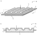
本発明の真空断熱材について図を用いて説明する。図1(a)は本発明の真空断熱材の一例を示す概略斜視図であり、図1(b)は図1(a)のX−X線断面図である。本発明の真空断熱材10は、対向する外包材1aおよび1bの周縁を封止して袋状とした中に、芯材2が内包されたものであり、内部が減圧されて真空状態となって密封されている。芯材2を介して対向する外包材1aおよび1bのうち、外包材1bの表面には、芯材2側に凸形状を成す折り目線部3が形成されており、真空断熱材10は折り目線部3において屈曲させることが可能である。なお、外包材1aおよび1bの周縁の封止された部分4が、真空断熱材10の端部4となる。また、本発明の真空断熱材の表面のうち、端部の封止面と平行に位置する表面を真空断熱材の平面、端部が形成された表面を真空断熱材の側面と称する場合がある。
The vacuum heat insulating material of this invention is demonstrated using figures. Fig.1 (a) is a schematic perspective view which shows an example of the vacuum heat insulating material of this invention, FIG.1 (b) is XX sectional drawing of Fig.1 (a). The vacuum
本発明によれば、真空断熱材が、芯材を覆うようにして対向する外包材の少なくとも一方に折り目線部を有することで、前記折り目線部をきっかけとして屈曲させることが可能となり、所望の形状に加工することができる。 According to the present invention, since the vacuum heat insulating material has the crease line portion on at least one of the facing outer packaging materials so as to cover the core material, it becomes possible to bend the crease line portion as a trigger, and a desired It can be processed into a shape.
以下、本発明の真空断熱材の各構成について説明する。 Hereinafter, each structure of the vacuum heat insulating material of this invention is demonstrated.
1.折り目線部
本発明における折り目線部は、対向する外包材の少なくとも一方に形成されるものである。前記折り目線部は、本発明の真空断熱材を屈曲させる際にきっかけとなる部分である。
1. Crease line part The crease line part in this invention is formed in at least one of the outer packaging material which opposes. The crease line portion is a portion that triggers when the vacuum heat insulating material of the present invention is bent.
前記折り目線部の断面形状は、真空断熱材の芯材側に凸形状を成すものであってもよく、芯材と反対側に凸形状を成すものであってもよい。
ここで、折り目線部が芯材側に凸形状であるとは、図1で示したように、折り目線部が真空断熱材の表面において溝を成していることをいう。一方、折り目線部が芯材と反対側に凸形状であるとは、後述する図4(b)で示すように、折り目線部が真空断熱材の表面から突出していることをいう。
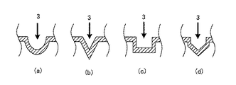
また、前記断面形状において、芯材側に凸形状を成す折り目線部の底部(以下、折り目線部の底部と称する場合がある。)、または芯材と反対側に凸形状を成す折り目線部の頂部(以下、折り目線部の頂部と称する場合がある。)は、角を有する形状であってもよく、曲率を有する形状であってもよい。具体的には、図2で例示されるように、半円形(図2(a))、三角形(図2(b))、四角形(図2(c))、台形、多角形(図2(d))、半楕円形等が挙げられる。
中でも、本発明においては、折り目線部の底部または頂部が曲率を有する形状であることが好ましい。真空断熱材を屈曲させる際に角部に応力が掛り、ピンホールが生じる場合があるからである。
The cross-sectional shape of the crease line portion may be a convex shape on the core material side of the vacuum heat insulating material, or a convex shape on the opposite side to the core material.
Here, the fact that the crease line portion has a convex shape on the core side means that the crease line portion forms a groove on the surface of the vacuum heat insulating material as shown in FIG. On the other hand, the fact that the crease line portion has a convex shape on the opposite side to the core means that the crease line portion protrudes from the surface of the vacuum heat insulating material as shown in FIG.
Further, in the cross-sectional shape, a bottom portion of a crease line portion forming a convex shape on the core material side (hereinafter sometimes referred to as a bottom portion of the crease line portion), or a crease line portion forming a convex shape on the opposite side to the core material. The top portion (hereinafter sometimes referred to as the top portion of the crease line portion) may have a corner shape or a curvature shape. Specifically, as illustrated in FIG. 2, a semicircle (FIG. 2A), a triangle (FIG. 2B), a quadrangle (FIG. 2C), a trapezoid, a polygon (FIG. 2 d)), semi-elliptical and the like.
Especially, in this invention, it is preferable that the bottom part or top part of a crease line part is a shape which has a curvature. This is because when the vacuum heat insulating material is bent, stress is applied to the corner portion and a pinhole may be generated.
前記折り目線の平面視上の形状としては、特に限定されるものではないが、屈曲の容易さから直線であることが好ましい。 The shape of the crease line in plan view is not particularly limited, but is preferably a straight line for ease of bending.
前記折り目線部の深さまたは高さとしては、折り目線部において真空断熱材が屈曲可能な大きさであればよい。具体的には、折り目線部の深さまたは高さが0.5mm〜2.0mmの範囲内であることが好ましく、中でも0.6mm〜1.5mmの範囲内であることが好ましい。折り目線部の深さまたは高さが前記範囲よりも大きいと、外包材の引張強度等によっては、屈曲時にピンホール等が発生する場合がある。一方、前記範囲よりも小さいと、折り目線部において真空断熱材を屈曲出来ない場合がある。
なお、折り目線部の深さまたは高さとは、真空断熱材の表面から折り目線部の底部または頂部までの長さをいう。
The depth or height of the crease line portion may be a size that allows the vacuum heat insulating material to be bent at the crease line portion. Specifically, the depth or height of the crease line portion is preferably in the range of 0.5 mm to 2.0 mm, and more preferably in the range of 0.6 mm to 1.5 mm. When the depth or height of the crease line portion is larger than the above range, a pinhole or the like may occur during bending depending on the tensile strength of the outer packaging material. On the other hand, if it is smaller than the above range, the vacuum heat insulating material may not be bent at the crease line.
In addition, the depth or height of a crease line part means the length from the surface of a vacuum heat insulating material to the bottom part or top part of a crease line part.
前記折り目線部の線幅については、特に限定されるものでは無く、本発明の真空断熱材の大きさ等に応じて適宜設定することができる。 The line width of the crease line portion is not particularly limited, and can be appropriately set according to the size of the vacuum heat insulating material of the present invention.
前記折り目線部の数は一本以上であれば特に限定されない。ここで、折り目線部は、その本数が多いほど真空断熱材の屈曲性が向上することから、曲面部や角部等の複雑な形状に真空断熱材を追従させ、密着させることが可能となる。これにより、真空断熱材と前記真空断熱材を配置する部位との間に空隙が生じにくくなり、前記空隙からの熱漏れが抑制されるため高い断熱性能を発揮することができる。一方、真空断熱材は折り目線部において厚さが小さくなることから、折り目線部の本数が多くなる程、真空断熱材全体としての断熱性能が低下する恐れがある。前記理由から、要求される屈曲性、および折り目線部の本数と断熱性能との相関をもとに設計される最適な本数を有することが好ましい。 The number of the crease line portions is not particularly limited as long as it is one or more. Here, as the number of the crease line portions increases, the flexibility of the vacuum heat insulating material improves, so that the vacuum heat insulating material can follow and adhere to a complicated shape such as a curved surface portion or a corner portion. . Thereby, it becomes difficult to produce a space | gap between a vacuum heat insulating material and the site | part which arrange | positions the said vacuum heat insulating material, and since the heat leak from the said space | gap is suppressed, a high heat insulation performance can be exhibited. On the other hand, since the thickness of the vacuum heat insulating material is reduced at the crease line portion, the heat insulation performance as the whole vacuum heat insulating material may be lowered as the number of the crease line portions is increased. For the above reasons, it is preferable to have an optimum number designed based on the required flexibility and the correlation between the number of crease lines and the heat insulation performance.
本発明において複数の折り目線部を有する場合、隣接する折り目線部の配置間隔としては、真空断熱材に求められる屈曲性等に応じて適宜設定することができるが、大きいことが好ましい。折り目線部の配置間隔が小さいと、折り目線部の数を多くすることができ、真空断熱材の屈曲性が増加する一方、真空断熱材の全体の厚さが小さくなり断熱性能が低下する場合があるからである。折り目線部の配置間隔としては、例えば1mmよりも大きいことが好ましく、中でも3mm以上であることが好ましい。 In the present invention, when a plurality of crease line portions are provided, the interval between adjacent crease line portions can be appropriately set according to the flexibility required for the vacuum heat insulating material, but is preferably large. When the arrangement interval of the crease line portions is small, the number of crease line portions can be increased and the flexibility of the vacuum heat insulating material is increased, while the overall thickness of the vacuum heat insulating material is reduced and the heat insulating performance is reduced. Because there is. The arrangement interval of the crease line portions is preferably larger than 1 mm, for example, and more preferably 3 mm or more.
本発明において複数の折り目線部を有する場合、前記折り目線部の平面視上のパターン(以下、平面パターンとする場合がある。)としては、本発明の真空断熱材に要求される屈曲性に応じて適宜設計することができる。例えば、図1(a)で示すように真空断熱材の縦また横の一方向に並列したパターンが挙げられるが、これに限定されない。他の平面パターンとしては、例えば一方向に対角線状のパターン、図3(a)で示すような縦横の格子状のパターン、図3(b)で示すような対角線が格子状のパターン、図3(c)で示すような三角格子状のパターン、図3(d)で示すような同心円状のパターン等が挙げられる。中でも、格子状のパターンを有することが好ましい。本発明の真空断熱材を多方向に屈曲させることが可能となり、加工性をより向上させることができるからである。
なお、図3は、折り目線部の平面視上のパターンの例を示す説明図である。
In the present invention, in the case of having a plurality of crease line portions, as a pattern in plan view of the crease line portions (hereinafter sometimes referred to as a plane pattern), the flexibility required for the vacuum heat insulating material of the present invention is obtained. It can be designed accordingly. For example, as shown in FIG. 1 (a), a pattern in which the vacuum heat insulating material is arranged in one vertical or horizontal direction is exemplified, but the present invention is not limited to this. Other planar patterns include, for example, a diagonal pattern in one direction, a vertical and horizontal grid pattern as shown in FIG. 3A, a diagonal pattern as shown in FIG. Examples thereof include a triangular lattice pattern as shown in (c) and a concentric pattern as shown in FIG. Among these, it is preferable to have a lattice pattern. This is because the vacuum heat insulating material of the present invention can be bent in multiple directions, and the workability can be further improved.
FIG. 3 is an explanatory diagram showing an example of a pattern in plan view of the crease line portion.
本発明において複数の折り目線部を有する場合、真空断熱材の側面から見た前記折り目線部の断面パターンとしては、本発明の真空断熱材に要求される屈曲性に応じて適宜設計することが出来る。例えば、図1(b)で示すように、全ての折り目線部3が芯材2側に凸形状を成すパターンであってもよく、全ての折り目線部が芯材と反対側に凸形状を成すパターンであっても良い。また、芯材側に凸形状を成す折り目線部と、芯材と反対側に凸形状を成す折り目線部とが交互にまたはランダムに混在するパターンであってもよい。
これらのパターンにおいては、隣接する折り目線部間に、外包材全体で構成させる面に沿った平坦部を介することが好ましい。本発明の真空断熱材全体としての平坦性が保てるからである。中でも芯材側に凸形状を成す折り目線部と、芯材と反対側に凸形状を成す折り目線部とが平坦部を介して交互に混在するパターンが好ましい。
さらに、芯材側に凸形状を成す折り目線部と芯材と反対側に凸形状を成す折り目線部とが平坦部を介さずに交互に連続する蛇腹パターンであってもよい。
In the present invention, when having a plurality of crease line parts, the cross-sectional pattern of the crease line part viewed from the side surface of the vacuum heat insulating material can be appropriately designed according to the flexibility required for the vacuum heat insulating material of the present invention. I can do it. For example, as shown in FIG. 1B, a pattern in which all the
In these patterns, it is preferable to place a flat portion along a surface formed by the entire outer packaging material between adjacent crease line portions. This is because the flatness of the entire vacuum heat insulating material of the present invention can be maintained. Among these, a pattern in which a crease line portion having a convex shape on the core material side and a crease line portion having a convex shape on the opposite side to the core material are alternately mixed via a flat portion is preferable.
Further, a bellows pattern in which a crease line portion having a convex shape on the core material side and a crease line portion having a convex shape on the opposite side to the core material are alternately continued without a flat portion may be used.
本発明において折り目線部は、対向する外包材の表面のうち少なくとも一方に有していればよいが、中でも、対向する外包材がそれぞれ折り目線部を有することが好ましい。本発明の真空断熱材を所望の方向により容易に屈曲させることができ、フレキシブル性が向上するからである。 In the present invention, the crease line portion only needs to be provided on at least one of the surfaces of the facing outer packaging material, but it is preferable that the facing outer packaging materials each have a crease line portion. This is because the vacuum heat insulating material of the present invention can be easily bent in a desired direction and the flexibility is improved.
対向する外包材がそれぞれ折り目線部を有する場合、例えば図4(a)に示すように、対向する外包材1bが共に、芯材2側に凸形状を成す折り目線部3が複数配置された同一のパターンを有するものであってもよく、図4(b)に示すように、対向する外包材1bが共に、芯材2と反対側に凸形状を成す折り目線部3が複数配置された同一のパターンを有するものであってもよい。また、図4(c)に示すように、対向する外包材1bのうち、一方は芯材2側に凸形状を成す折り目線部3Aを有し、他方は芯材2と反対側に凸形状を成す折り目線部3Bを有するものであってもよい。中でも、一方の前記外包材は、芯材側に凸形状を成す折り目線部を有し、他方の外包材は、前記芯材と反対側に凸形状を成す前記折り目線部を有し、一方の前記外包材の前記折り目線部と、他方の前記外包材の前記折り目線部とが、対向する位置にあることが好ましい。さらにこのとき、一方の前記外包材の前記折り目線部と、他方の前記外包材の前記折り目線部とが対向することによって、それらが外包材全体の厚み方向から見たときに少なくとも一部が重なることが好ましい。本発明の真空断熱材を両方向に屈曲させることが可能となり、加工性をより向上させることができるからである。また、折り目線部が位置する部分の芯材の厚さを確保することができ、真空断熱材の断熱性能の低下を抑えることができるからである。
When the opposing outer packaging materials each have a crease line portion, for example, as shown in FIG. 4A, both the opposing
また、対向する外包材が共に、芯材側に凸形状を成す折り目線部と、前記芯材と反対側に凸形状を成す折り目線部とが混在するパターンを有していてもよい。このとき、図5に示すように、対向する外包材1bが共に、芯材2側に凸形状を成す折り目線部3Aと、芯材2と反対側に凸形状を成す折り目線部3Bとが平坦部Sを介して混在するパターンを有していてもよく、図示しないが芯材側に凸形状を成す折り目線部と、前記芯材と反対側に凸形状を成す折り目線部とが、平坦部を介さずに交互に連続する蛇腹パターンを有していても良い。
中でも本発明においては、芯材側に凸形状を成す折り目線部と、前記芯材と反対側に凸形状を成す折り目線部とが平坦部を介して混在するパターンを有することが好ましい。本発明の真空断熱材を、全体としての平坦性を保ちつつ、所望の方向により容易に屈曲させることができ、フレキシブル性が向上するからである。
さらにこのとき、一方の外包材において芯材側に凸形状を成す折り目線部と、他方の外包材において芯材と反対側に凸形状を成す折り目線部とが対向する位置にあることが好ましい。その理由については先に説明した理由と同様である。
なお、図4および図5は、本発明の真空断熱材の他の例を示す概略断面図である。
Further, both of the facing outer packaging materials may have a pattern in which a crease line portion having a convex shape on the core material side and a crease line portion having a convex shape on the opposite side to the core material are mixed. At this time, as shown in FIG. 5, the opposing
In particular, in the present invention, it is preferable to have a pattern in which a crease line portion having a convex shape on the core material side and a crease line portion having a convex shape on the opposite side to the core material are mixed via a flat portion. This is because the vacuum heat insulating material of the present invention can be easily bent in a desired direction while maintaining the flatness as a whole, and the flexibility is improved.
Further, at this time, it is preferable that the crease line portion that forms a convex shape on the core material side in one outer packaging material and the crease line portion that forms a convex shape on the opposite side to the core material in the other outer packaging material. . The reason is the same as described above.
4 and 5 are schematic cross-sectional views showing other examples of the vacuum heat insulating material of the present invention.
前記折り目線部は、外包材の少なくとも芯材と接する領域内に有していればよいが、真空断熱材の端部上に有していてもよい。本発明の真空断熱材の端部における屈曲性も向上するからである。 The crease line portion may be provided in at least a region in contact with the core material of the outer packaging material, but may be provided on an end portion of the vacuum heat insulating material. This is because the flexibility at the end of the vacuum heat insulating material of the present invention is also improved.
2.外包材
本発明における外包材は、前記芯材を覆うようにして対向するものであり、対向する前記外包材の周縁が封止されたものである。
2. Outer packaging material The outer packaging material in the present invention is opposed so as to cover the core material, and the periphery of the opposed outer packaging material is sealed.
本発明における外包材は、芯材を覆うことができ、ガスバリア性を有するものであればよく、通常、保護層、ガスバリア層および熱溶着層が少なくともこの順で積層されたものが用いられる。
以下、前記外包材の各部材について説明する。
The outer packaging material in the present invention may be any material as long as it can cover the core material and has a gas barrier property, and a material in which a protective layer, a gas barrier layer, and a heat welding layer are laminated at least in this order is usually used.
Hereinafter, each member of the outer packaging material will be described.
(a)熱溶着層
前記熱溶着層は、本発明の真空断熱材において芯材と接する部位である。また、対向する外包材の周縁を封止する際に封止面を形成する部位である。
(A) Thermal welding layer The said thermal welding layer is a site | part which contact | connects a core material in the vacuum heat insulating material of this invention. Moreover, it is a site | part which forms a sealing surface when sealing the periphery of the outer packaging material which opposes.
前記熱溶着層の材料としては、加熱によって溶融し、融着することが可能であることから熱可塑性樹脂が好ましく、例えばポリエチレンや未延伸ポリプロピレン(CPP)等のポリオレフィン系樹脂、ポリ酢酸ビニル系樹脂、ポリ塩化ビニル系樹脂、ポリ(メタ)アクリル系樹脂、ウレタン樹脂等が挙げられる。 The material of the heat-welding layer is preferably a thermoplastic resin because it can be melted and fused by heating. For example, a polyolefin resin such as polyethylene or unstretched polypropylene (CPP), a polyvinyl acetate resin , Polyvinyl chloride resin, poly (meth) acrylic resin, urethane resin and the like.
また、上述した樹脂の他に、アンチブロッキング剤、滑剤、難燃化剤、有機充填剤等の他の材料を含んでいてもよい。 In addition to the above-described resin, other materials such as an anti-blocking agent, a lubricant, a flame retardant, and an organic filler may be included.
前記熱溶着層の融点としては、例えば80℃〜300℃の範囲内であることが好ましく、中でも100℃〜250℃の範囲内であることが好ましい。熱溶着層の融点を前記範囲内とすることにより、本発明の真空断熱材の使用環境下において、外包材の封止面の剥離を抑制することができる。 As melting | fusing point of the said heat welding layer, it is preferable to exist in the range of 80 to 300 degreeC, for example, and it is preferable to exist in the range of 100 to 250 degreeC especially. By setting the melting point of the heat-welded layer within the above range, peeling of the sealing surface of the outer packaging material can be suppressed under the usage environment of the vacuum heat insulating material of the present invention.
前記熱溶着層の厚さとしては、例えば20μm〜100μmの範囲内が好ましく、中でも25μm〜90μmの範囲内が好ましく、特に30μm〜80μmの範囲内が好ましい。熱溶着層の厚さが前記範囲よりも大きいと、外包材のガスバリア性が低下する場合等があり、一方、前記範囲よりも小さいと、接着力が得られない場合がある。 The thickness of the heat welding layer is preferably, for example, in the range of 20 μm to 100 μm, more preferably in the range of 25 μm to 90 μm, and particularly preferably in the range of 30 μm to 80 μm. When the thickness of the heat-welded layer is larger than the above range, the gas barrier property of the outer packaging material may be lowered. On the other hand, when the thickness is smaller than the above range, the adhesive force may not be obtained.
(b)ガスバリア層
前記ガスバリア層は、通常、熱溶着層と保護層との間に形成される部位である。
(B) Gas barrier layer The said gas barrier layer is a site | part normally formed between a heat welding layer and a protective layer.
前記ガスバリア層としては、例えばアルミニウム、ニッケル、ステンレス、鉄、銅、チタニウム等の金属箔、金属、金属酸化物、酸化珪素等の無機物等を樹脂フィルムの片面に蒸着した蒸着フィルム、蒸着フィルムにポリビニルアルコール系樹脂およびエチレンビニルアルコール共重合体の少なくともいずれかを含有するガスバリア性組成物によるガスバリア性塗布膜を設けたもの等、一般にガスバリア層として使用されるものを用いることもできる。 Examples of the gas barrier layer include a metal foil such as aluminum, nickel, stainless steel, iron, copper, and titanium, a vapor deposition film in which an inorganic substance such as a metal, metal oxide, and silicon oxide is vapor-deposited on one side of the resin film, and polyvinyl on the vapor deposition film. Those generally used as a gas barrier layer such as those provided with a gas barrier coating film of a gas barrier composition containing at least one of an alcohol-based resin and an ethylene vinyl alcohol copolymer can also be used.
前記ガスバリア層は、単層であってもよく、同一材料から成る層または異なる材料から成る層を積層させた多層体であってもよい。
また、前記ガスバリア層は、ガスバリア性能および他の層との密着性の向上が図れるという点から、コロナ放電処理等の表面処理が施されていてもよい。
The gas barrier layer may be a single layer or a multilayer body in which layers made of the same material or layers made of different materials are laminated.
The gas barrier layer may be subjected to a surface treatment such as a corona discharge treatment from the viewpoint that the gas barrier performance and the adhesion with other layers can be improved.
ガスバリア層の厚さとしては、例えば、2μm〜50μmの範囲内、中でも5μm〜12μmの範囲内であることが好ましい。ガスバリア層の厚さが前記範囲よりも小さいと、折り目線部を形成する際にピンホール等が生じやすくなり、ガスバリア性が低下する場合があり、一方、前記範囲よりも大きいと、本発明の真空断熱材においてヒートブリッジが生じやすくなり、断熱性能が低下する場合があるからである。 The thickness of the gas barrier layer is, for example, preferably in the range of 2 μm to 50 μm, and more preferably in the range of 5 μm to 12 μm. If the thickness of the gas barrier layer is smaller than the above range, pinholes and the like are likely to occur when forming the crease line portion, and the gas barrier property may be deteriorated. This is because heat bridge is likely to occur in the vacuum heat insulating material, and the heat insulating performance may be deteriorated.
前記ガスバリア層のガスバリア性としては、酸素透過度が0.5cc・m−2・day−1以下であることが好ましく、中でも0.1cc・m−2・day−1以下であることが好ましい。また、水蒸気透過度が0.2cc・m−2・day−1以下であることが好ましく、中でも0.1cc・m−2・day−1以下であることが好ましい。前記ガスバリア層の酸素および水蒸気透過度が上述の範囲内であることにより、外部より浸透した水分やガス等を内部の芯材まで浸透しにくくすることができる。
なお、前記酸素透過度は、JIS−K−7126Bに基づき、温度23℃、湿度90%RHの条件下において酸素透過度測定装置(米国モコン(MOCON)社製、オクストラン(OXTRAN))を用いて測定した値である。 また、前記水蒸気透過度は、温度40℃、湿度90%RHの条件で、水蒸気透過度測定装置(米国モコン(MOCON)社製、パ−マトラン(PERMATRAN))を用いて測定した値である。
As the gas barrier properties of the gas barrier layer is preferably an oxygen permeability is not more than 0.5cc · m -2 · day -1, is preferably Among them 0.1cc · m -2 · day -1 or less. It is preferable that water vapor permeability is not more than 0.2cc · m -2 · day -1, is preferably Among them 0.1cc · m -2 · day -1 or less. When the oxygen and water vapor permeability of the gas barrier layer is within the above-described range, it is possible to make it difficult for moisture, gas, and the like that have permeated from the outside to penetrate into the inner core material.
The oxygen permeability is based on JIS-K-7126B using an oxygen permeability measuring device (Oxtran manufactured by MOCON, USA) under the conditions of a temperature of 23 ° C. and a humidity of 90% RH. It is a measured value. The water vapor permeability is a value measured using a water vapor permeability measuring device (manufactured by MOCON, USA, PERMATRAN) under the conditions of a temperature of 40 ° C. and a humidity of 90% RH.
(c)保護層
前記保護層は、本発明の真空断熱材において最外層(最表層)となる部位である。前記保護層は、本発明の真空断熱材の内部を保護するに十分な強度を有し、耐熱性、防湿性、耐ピンホ−ル性、耐突き刺し性等に優れたものであることが好ましい。
(C) Protective layer The said protective layer is a site | part used as the outermost layer (outermost layer) in the vacuum heat insulating material of this invention. The protective layer preferably has sufficient strength to protect the inside of the vacuum heat insulating material of the present invention, and is excellent in heat resistance, moisture resistance, pinhole resistance, puncture resistance, and the like.
前記保護層としては、熱溶着層よりも高融点の樹脂を用いたものであればよく、シート状でもフィルム状でもよい。このような保護層として、例えば、ナイロン系樹脂、ポリエステル系樹脂、ポリアミド系樹脂、ポリプロピレン系樹脂等のシートまたはフィルム等が挙げられる。 The protective layer only needs to use a resin having a melting point higher than that of the heat welding layer, and may be in the form of a sheet or film. Examples of such a protective layer include sheets or films of nylon resin, polyester resin, polyamide resin, polypropylene resin, and the like.
前記保護層は、単層であってもよく、同一材料から成る層または異なる材料から成る層を積層させて多層としたものであってもよい。
また前記保護層は、他の層との密着性の向上が図れるという点から、コロナ放電処理等の表面処理が施されていてもよい。
The protective layer may be a single layer, or may be a multilayer formed by laminating layers made of the same material or layers made of different materials.
The protective layer may be subjected to a surface treatment such as a corona discharge treatment from the viewpoint of improving the adhesion with other layers.
前記保護層の厚さとしては、熱溶着層およびガスバリア層を保護することができる厚さであれば特に限定されるものではないが、一般的に5μm〜80μm程度である。 The thickness of the protective layer is not particularly limited as long as it can protect the heat welding layer and the gas barrier layer, but is generally about 5 μm to 80 μm.
(d)外包材
前記外包材を構成する各層は、直接接触して積層されていてもよく、層間接着剤を介して積層されていてもよい。層間接着剤については、一般に真空断熱材用の外包材に使用される接着剤を用いることができる。
(D) Outer packaging material Each layer constituting the outer packaging material may be directly contacted and laminated, or may be laminated via an interlayer adhesive. About an interlayer adhesive agent, the adhesive agent generally used for the outer packaging material for vacuum heat insulating materials can be used.
前記外包材は、保護層またはガスバリア層を複数有するものであってもよい。例えば、熱溶着層と保護層との間にガスバリア層を2層以上設けてもよく、熱溶着層およびガスバリア層の上に、保護層を2層以上設けてもよい。また、熱溶着層とガスバリア層との間に別の保護層が設けられてもよい。
また、前記外包材は、アンカーコート層、耐ピンホール層等の任意の層を有していても良い。
The outer packaging material may have a plurality of protective layers or gas barrier layers. For example, two or more gas barrier layers may be provided between the heat welding layer and the protective layer, and two or more protective layers may be provided on the heat welding layer and the gas barrier layer. Further, another protective layer may be provided between the heat welding layer and the gas barrier layer.
The outer packaging material may have an arbitrary layer such as an anchor coat layer or a pinhole-resistant layer.
前記外包材の膜厚としては、特に限定されるものではないが、後述する方法により折り目線部を形成することができ、所望のガスバリア性を有する厚さであればよく、例えば、30μm〜200μmの範囲内であることが好ましく、50μm〜150μmの範囲内であることが好ましい。 The film thickness of the outer packaging material is not particularly limited, but may be any thickness as long as the crease line portion can be formed by a method described later and has a desired gas barrier property, for example, 30 μm to 200 μm. It is preferable to be within the range of 50 μm to 150 μm.
前記外包材の引張強度としては、50N以上であることが好ましく、中でも80N以上であることが好ましい。本発明の真空断熱材を屈曲させる際に破断等が生じにくくなるためである。なお、前記引張強度は、JIS−Z−1707に基づいて測定した値である。 The tensile strength of the outer packaging material is preferably 50N or more, and more preferably 80N or more. This is because breakage or the like hardly occurs when the vacuum heat insulating material of the present invention is bent. The tensile strength is a value measured based on JIS-Z-1707.
前記外包材の積層方法としては、特に限定されるものではなく、一方の最表層に保護層を有し、他方の最表層に熱溶着層を有するように各層を積層できる方法であればよく、ドライラミネーション法、押出法等の公知の積層方法を用いることができる。 The method for laminating the outer packaging material is not particularly limited as long as it is a method that can laminate each layer so that one outermost layer has a protective layer and the other outermost layer has a heat-welded layer, A known laminating method such as a dry lamination method or an extrusion method can be used.
3.芯材
本発明における芯材は、前記外包材により覆われて、外包材に内包されるものである。本発明では、真空断熱材の内部において、外包材の折り目線部に対向する位置に芯材が配置されていることが好ましい。本発明の真空断熱材を折り目線部で屈曲させた場合に、真空断熱材の厚みが薄くなって断熱性能が低下することを防ぐことができるからである。
3. Core material The core material in this invention is covered with the said outer packaging material, and is included in an outer packaging material. In this invention, it is preferable that the core material is arrange | positioned in the position which opposes the crease line part of an outer packaging material inside a vacuum heat insulating material. This is because, when the vacuum heat insulating material of the present invention is bent at the crease line portion, it is possible to prevent the heat insulating performance from being lowered due to the reduced thickness of the vacuum heat insulating material.
本発明では、前記芯材は板状であることが好ましい。前記芯材が板状であるとは、本発明の真空断熱材の内部において、後述する芯材の主材料が、真空断熱材の幅(平面)方向に沿った面で連続していることをいう。板状の芯材を用いることによって、真空断熱材の折り目線部に対向する位置に芯材を容易に配置することができる。そして、本発明では、外包材が折り目線部を有するので、板状の芯材を用いた場合であっても、真空断熱材を屈曲させることが可能になる。
なお、本発明の真空断熱材の内部において、芯材は、真空断熱材の幅(平面)方向に沿った面全体で完全につながっている必要はなく、切断されている箇所がある程度存在していてもよい。なお、切断されている箇所とは、引っ張らなくても自然に分離する箇所をいう。ただし、芯材は、好ましくは100分離以下、より好ましくは10分離以下に止めることが、真空断熱材の折り目線部に対向する位置に切断されている箇所をできる限り配置させないようにする観点から好ましい。
板状の芯材としては、例えば、後述する芯材の主材料を板状に成型した成型体、または、後述する芯材の主材料を真空断熱材の内部で外圧によって板状につなげた密集体等が挙げられる。
In the present invention, the core material is preferably plate-shaped. The said core material is plate-shaped in the inside of the vacuum heat insulating material of this invention that the main material of the core material mentioned later is continuing in the surface along the width | variety (plane) direction of a vacuum heat insulating material. Say. By using a plate-shaped core material, the core material can be easily disposed at a position facing the crease line portion of the vacuum heat insulating material. And in this invention, since an outer packaging material has a crease line part, even if it is a case where a plate-shaped core material is used, it becomes possible to bend a vacuum heat insulating material.
In addition, in the inside of the vacuum heat insulating material of the present invention, the core material does not need to be completely connected over the entire surface along the width (plane) direction of the vacuum heat insulating material, and there are some cut portions. May be. In addition, the location cut | disconnected means the location isolate | separated naturally even if it does not pull. However, the core material is preferably not more than 100 separations, more preferably not more than 10 separations, from the viewpoint of avoiding disposing as much as possible a portion that is cut at a position facing the crease line portion of the vacuum heat insulating material. preferable.
As the plate-like core material, for example, a molded body obtained by molding a main material of a core material described later into a plate shape, or a dense material in which a main material of a core material described later is connected in a plate shape by external pressure inside a vacuum heat insulating material. A collection etc. are mentioned.
芯材の主材料としては、一般に真空断熱材の芯材として使用される材料を用いることができる。例えばシリカ、パーライト、クレー、タルク等の粉体、ウレタンフォーム、スチレンフォーム、フェノールフォーム等の発泡体、ガラス繊維、アルミナ繊維、シリカアルミナ繊維、シリカ繊維、セラミック繊維、ロックウール等の繊維体等が挙げられる。これらの芯材の主材料は、それ自体が多孔質であることが好ましい。
これらの主材料は、単体で用いても良く2種以上の材料を混合して用いてもよい。
As a main material of a core material, the material generally used as a core material of a vacuum heat insulating material can be used. For example, powders such as silica, pearlite, clay, talc, foams such as urethane foam, styrene foam, phenol foam, fiber bodies such as glass fiber, alumina fiber, silica alumina fiber, silica fiber, ceramic fiber, rock wool, etc. Can be mentioned. It is preferable that the main material of these core materials is itself porous.
These main materials may be used alone or as a mixture of two or more materials.
また、前記芯材は、外部から浸透する微量の水分やガス等による経時的な真空度の低下を防止するためにゲッター剤を含んでいても良い。中でも断熱性能の低下を防ぐために、芯材の主材料およびゲッター剤のみが外包材に内包されることが好ましい。
ゲッター剤としては、従来より真空断熱材に用いられる材料とすることができ、例えば、ドーソナイト、ハイドロタルサイト、金属水酸化物、モレキュラーシーブス、シリカゲル、酸化カルシウム、ゼオライト、疎水性ゼオライト、活性炭等が挙げられる。
Further, the core material may contain a getter agent in order to prevent a decrease in the degree of vacuum over time due to a minute amount of moisture or gas that permeates from the outside. In particular, in order to prevent a decrease in heat insulation performance, it is preferable that only the core material and the getter agent are included in the outer packaging material.
As the getter agent, it can be a material conventionally used for vacuum heat insulating materials, for example, dosonite, hydrotalcite, metal hydroxide, molecular sieves, silica gel, calcium oxide, zeolite, hydrophobic zeolite, activated carbon, etc. Can be mentioned.
前記芯材としては、熱伝導率の低いものであることが好ましい。中でも、芯材空隙率が50%以上、特に90%以上の多孔質であることが好ましい。 The core material preferably has a low thermal conductivity. Among them, a porous material having a core material porosity of 50% or more, particularly 90% or more is preferable.
前記芯材の厚さとしては、折り目線部において屈曲可能な厚さであればよく、外包材の組成や強度に応じて適宜設定されるものである。外包材の強度が大きいほど、芯材を厚くすることが可能である。減圧後の芯材の厚さとしては、1mm〜10mmの範囲内であることが好ましい。 The thickness of the core material may be any thickness that can be bent at the crease line portion, and is appropriately set according to the composition and strength of the outer packaging material. The core material can be thickened as the strength of the outer packaging material increases. The thickness of the core material after decompression is preferably in the range of 1 mm to 10 mm.
4.真空断熱材
本発明においては、外包材と芯材とが直接に接触していることが好ましい。外包材と芯材との間に他の部材が存在すると、真空断熱材の内部の多孔性の低下やヒートブリッジによって、真空断熱材の断熱性が低下するおそれがあり、また、折り目線部による屈曲性を阻害するおそれがあるためである。したがって、本発明においては、通常、真空断熱材の内部に屈曲性に寄与する部材は不要である。
ここで、屈曲性に寄与する部材とは、例えば、アルミ、鉄、SUS等の金属、または有機樹脂を主体とし塑性変形性を有するものであって、波板状、プリーツ状、蛇腹状等の形状を有する骨材をいう。本発明では外包材に折り目線部を有するので、真空断熱材の内部に屈曲性に寄与する部材を有さなくても、真空断熱材に屈曲性を付与することが可能であるという利点を有する。
4). Vacuum heat insulating material In the present invention, it is preferable that the outer packaging material and the core material are in direct contact with each other. If there is another member between the outer packaging material and the core material, there is a risk that the heat insulation property of the vacuum heat insulating material will decrease due to the decrease in the porosity inside the vacuum heat insulating material or the heat bridge. This is because there is a possibility of inhibiting the flexibility. Therefore, in the present invention, a member that contributes to flexibility is usually unnecessary inside the vacuum heat insulating material.
Here, the member that contributes to the flexibility is, for example, a metal such as aluminum, iron, SUS, or the like, or an organic resin, and has plastic deformability, such as a corrugated plate shape, a pleated shape, and a bellows shape. An aggregate having a shape. In the present invention, since the outer wrapping material has a crease line portion, it has an advantage that it is possible to impart flexibility to the vacuum heat insulating material without having a member that contributes to flexibility inside the vacuum heat insulating material. .
また、本発明の真空断熱材においては、芯材が外包材の折り目線部の形状に追従していてもよく、追従していなくてもよいが、追従していることが好ましい。芯材が折り目線部の形状に追従することで、前記折り目線部において真空断熱材をさらに屈曲しやすくなるからである。このとき、芯材は折り目線部の形状に隙間無く追従されることが特に好ましい。芯材と折り目線部との間に空間があると、当該空間の真空度が低下した際に、空気の対流による熱移動が生じる場合があるからである。 Moreover, in the vacuum heat insulating material of the present invention, the core material may or may not follow the shape of the crease line portion of the outer packaging material, but preferably follows. This is because the core material follows the shape of the crease line portion, whereby the vacuum heat insulating material is further easily bent at the crease line portion. At this time, it is particularly preferable that the core material follows the shape of the crease line portion without any gap. This is because if there is a space between the core material and the crease line portion, heat transfer due to air convection may occur when the degree of vacuum in the space decreases.
本発明の真空断熱材は、内部を減圧し密封したものであり、具体的には内部の真空度が5Pa以下であることが好ましい。真空断熱材内部の真空度を前記範囲内とすることにより、内部に残存する空気の対流による熱伝導を小さいものとすることができ、優れた断熱性を発揮することが可能となる。 The vacuum heat insulating material of the present invention is one in which the inside is depressurized and sealed, and specifically, the degree of vacuum inside is preferably 5 Pa or less. By setting the degree of vacuum inside the vacuum heat insulating material within the above range, heat conduction due to convection of air remaining inside can be reduced, and excellent heat insulation can be exhibited.
また、本発明の真空断熱材の熱伝導率は低いことが好ましく、例えば、25℃における熱伝導率(初期熱伝導率)が15mW・m−1・K−1以下であることが好ましく、中でも10mW・m−1・K−1以下であることが好ましく、特に5mW・m−1・K−1以下であることが好ましい。真空断熱材の熱伝導率を前記範囲とすることにより、前記真空断熱材は熱を外部に伝導しにくくなることから、高い断熱効果を奏することができるからである。なお、前記熱伝導率は、JIS−A−1412−3に従い熱伝導率測定装置オートラムダ(HC−074 英弘精機製)を用いた熱流計法により測定された値である。 The thermal conductivity of the vacuum heat insulating material of the present invention is low it is preferable, for example, preferably a thermal conductivity at 25 ° C. (initial thermal conductivity) is less than 15mW · m -1 · K -1, inter alia It is preferably 10 mW · m −1 · K −1 or less, and particularly preferably 5 mW · m −1 · K −1 or less. This is because, by setting the thermal conductivity of the vacuum heat insulating material within the above range, the vacuum heat insulating material is less likely to conduct heat to the outside, so that a high heat insulating effect can be achieved. In addition, the said heat conductivity is the value measured by the heat flow meter method using the heat conductivity measuring apparatus auto-lambda (made by HC-074 Hidehiro Seiki) according to JIS-A-1412-3.
本発明の真空断熱材はガスバリア性が高いことが好ましい。外部からの水分や酸素等の浸透による真空度の低下を防止することができるからである。前記真空断熱材のガスバリア性については、上述した「2.外包材」の項で説明したガスバリア性と同様であるため、ここでの説明は省略する。 The vacuum heat insulating material of the present invention preferably has a high gas barrier property. This is because it is possible to prevent a decrease in the degree of vacuum due to penetration of moisture, oxygen, etc. from the outside. Since the gas barrier property of the vacuum heat insulating material is the same as the gas barrier property described in the above-mentioned section “2. Outer packaging material”, description thereof is omitted here.
5.製造方法
本発明の真空断熱材の製造方法としては、予め折り目線を付した外包材を用いて芯材を覆い、外包材の周縁を封止して減圧密封する方法が好ましい。減圧密封する際に、外包材の折り目線部の形状に芯材を追従させることができるからである。
なお、本発明の真空断熱材の製造方法については、後述する「B.真空断熱材の製造方法」の項で説明する。
5. Manufacturing method As a manufacturing method of the vacuum heat insulating material of this invention, the method of covering a core material using the outer packaging material which attached the crease line beforehand, sealing the periphery of an outer packaging material, and sealing under reduced pressure is preferable. This is because the core material can follow the shape of the crease line portion of the outer packaging material when sealing under reduced pressure.
In addition, the manufacturing method of the vacuum heat insulating material of this invention is demonstrated in the term of the "B. manufacturing method of a vacuum heat insulating material" mentioned later.
6.用途
本発明の真空断熱材は、熱源部もしくは被保温部を有し、断熱性が求められる機器、住宅等の物品に用いることができる。なお、「熱源部」とは、機器自体が駆動することにより、当該機器本体または機器内部において発熱する部位をいうものであり、例えば電源やモーター等をいう。また、「被保温部」とは、機器本体または内部に熱源部を有さないが、前記機器が外部の熱源から熱を受けて、高温になる部位をいう。
熱源部もしくは被保温部を有し、断熱性が求められる物品として、例えば、自然冷媒ヒートポンプ給湯機(登録商標「エコキュート」)、冷蔵庫、炊飯ジャー、ポット、電子レンジ、業務用オーブン、IHクッキングヒーター、OA機器等の電化機器、自動販売機、貯湯タンク、保温タンク、配管設備における配管、自動車等が挙げられる。前記物品は、曲面部および角部の少なくとも一方を有することが好ましい。
6). Use The vacuum heat insulating material of this invention has a heat-source part or a heat retaining part, and can be used for articles | goods, such as an apparatus and a house where heat insulation is calculated | required. Note that the “heat source section” refers to a portion that generates heat in the device main body or inside the device when the device itself is driven, and refers to, for example, a power source or a motor. The “insulated part” refers to a part that does not have a heat source part in the apparatus main body or inside, but the apparatus is heated by receiving heat from an external heat source.
As an article having a heat source part or a heated part and requiring heat insulation, for example, a natural refrigerant heat pump water heater (registered trademark “Ecocute”), a refrigerator, a rice cooker, a pot, a microwave oven, a commercial oven, an IH cooking heater, Electric appliances such as OA equipment, vending machines, hot water storage tanks, heat insulation tanks, piping in piping facilities, automobiles, and the like. The article preferably has at least one of a curved surface portion and a corner portion.
B.真空断熱材の製造方法
次に、本発明の真空断熱材の製造方法について説明する。本発明の真空断熱材の製造方法は、外包材に折り目線部を形成する折り目線部形成工程と、前記折り目線部が形成された前記外包材を用いて芯材を覆い、次に内部を減圧し密封する封止工程と、を有することを特徴とする製造方法である。
B. Next, the manufacturing method of the vacuum heat insulating material of this invention is demonstrated. The method for manufacturing a vacuum heat insulating material according to the present invention includes a crease line portion forming step for forming a crease line portion in an outer packaging material, and the core material is covered with the outer packaging material on which the crease line portion is formed, and then the inside is covered. And a sealing step of reducing pressure and sealing.
本発明の真空断熱材の製造方法について、図を例示して説明する。図6は本発明の真空断熱材の製法方法の一例を示す工程図である。なお、図6(b)〜(d)においては外包材の各層構成についての図示は省略する。
まず、少なくとも保護層11、ガスバリア層12および熱溶着層13が積層されてなる外包材1aを準備する(図6(a))。
次に、転写版として表面の凸部を有するエンボス版胴51a、および凸部と雄雌型の関係を有し噛合可能な凹部を有するエンボス圧胴51bを縦列し、その間に外包材1aを通してX方向に搬送させる。エンボス版胴51aをR1方向へ、エンボス圧胴51bをR2方向へ回転させながら外包材1aを押圧して折り目線部3を形成し(図6(b))、得られた外包材1bを所望の長さで切断する。
続いて、折り目線部3を有する外包材1bと折り目線部を有さない外包材1aとを、熱溶着層が内側となるように重ね、周縁のうち開口となる一辺以外の辺を封止して袋状とし、その中に芯材2を入れて覆い、内部を減圧Yしながら開口を封止し密封する(図6(c))。これにより、対向する外包材の一方に折り目線部3を有する真空断熱材10を製造することができる(図6(d))。なお、図6(b)が折り目線部形成工程、図6(c)〜(d)が封止工程である。
The manufacturing method of the vacuum heat insulating material of the present invention will be described with reference to the drawings. FIG. 6 is a process diagram showing an example of a method for producing a vacuum heat insulating material according to the present invention. In addition, illustration about each layer structure of an outer packaging material is abbreviate | omitted in FIG.6 (b)-(d).
First, an
Next, an
Subsequently, the
本発明によれば、折り目線部を予め形成した外包材を使って、真空断熱材を製造することにより、油圧ローラーや金型プレス等を用いて真空断熱材を押圧することなく、真空断熱材に折り目線部を付すことができる。これにより、前記折り目線部において屈曲が可能な真空断熱材を得ることができる。 According to the present invention, a vacuum heat insulating material can be manufactured without using a hydraulic roller, a die press, or the like, by manufacturing a vacuum heat insulating material using an outer packaging material in which a crease line portion is formed in advance. A crease line part can be attached to. Thereby, the vacuum heat insulating material which can be bent in the said crease line part can be obtained.
以下、本発明の真空断熱材の製造方法について、工程ごとに説明する。 Hereinafter, the manufacturing method of the vacuum heat insulating material of this invention is demonstrated for every process.
1.折り目線形成工程
本発明における折り目線形成工程は、外包材に折り目線部を形成する工程である。
1. Crease line forming step The crease line forming step in the present invention is a step of forming a crease line portion in the outer packaging material.
(1)外包材
まず、本工程に用いられる外包材について説明する。前記外包材は、芯材を覆うことができ、ガスバリア性を有するものであればよく、通常、保護層、ガスバリア層および熱溶着層が少なくともこの順で積層されたものが用いられる。
前記外包材の各層については、「A.真空断熱材」の項で説明した外包材の各層と同様とすることができるため、ここでの説明は省略する。
(1) Outer packaging material First, the outer packaging material used in this step will be described. The outer packaging material may be any material that can cover the core material and has gas barrier properties. Usually, a material in which a protective layer, a gas barrier layer, and a heat welding layer are laminated in at least this order is used.
About each layer of the said outer packaging material, since it can be set to be the same as that of each layer of the outer packaging material demonstrated in the term of "A. vacuum heat insulating material", description here is abbreviate | omitted.
(2)折り目線部の形成方法
次に、本工程において外包材に折り目線部を形成する方法について説明する。
外包材に折り目線部を形成する方法としては、折り目線部が所望の形状、パターン等となるように形成可能な方法であれば特に限定されない。
このような方法としては、例えば、表面に折り目線部を転写形成するための凹凸形状を有する転写版(以下、エンボス版と称する場合がある。)で外包材を押圧する第1態様、外包材を凹凸状に仮折りした状態で押圧する第2態様の2つの態様が挙げられる。
以下、折り目線部の形成方法について、各態様に分けて説明する。
(2) Formation method of crease line part Next, the method of forming a crease line part in an outer packaging material in this process is demonstrated.
The method for forming the crease line portion on the outer packaging material is not particularly limited as long as it can be formed so that the crease line portion has a desired shape, pattern, or the like.
As such a method, for example, a first aspect in which an outer packaging material is pressed with a transfer plate having a concavo-convex shape for transferring a crease line portion on the surface (hereinafter sometimes referred to as an embossed plate), an outer packaging material There are two modes of the second mode of pressing in a state of being temporarily folded into a concavo-convex shape.
Hereinafter, the method of forming the crease line portion will be described separately for each aspect.
(a)第1態様
本態様は、表面に凹凸形状を有する転写版で外包材を押圧する方法である。具体的には、エンボス版胴およびエンボス圧胴間に外包材を通しながら押圧して折り目線部を転写形成する方法、平版プレスの下板および上板に凸部を有する転写版および凹部を有する転写版を備え、上板および下板間に外包材を通して上下方向から押圧して折り目線部を転写形成する方法等が挙げられる。なお、エンボス圧胴およびエンボス版胴をエンボスロールと称する場合がある。
本態様では、転写版の凸部の形状が外包材に転写されることで、折り目線部を形成することができる。
(A) 1st aspect This aspect is the method of pressing an outer packaging material with the transfer plate which has uneven | corrugated shape on the surface. Specifically, a method of transferring and forming a crease line portion by pressing an outer packaging material between an embossed plate cylinder and an embossed impression cylinder, a transfer plate having convex portions on a lower plate and an upper plate of a lithographic press, and a concave portion Examples thereof include a method in which a transfer plate is provided and a crease line portion is transferred and formed by pressing the outer packaging material between the upper plate and the lower plate from above and below. The embossing impression cylinder and the embossing plate cylinder may be referred to as an embossing roll.
In this aspect, the crease line portion can be formed by transferring the shape of the convex portion of the transfer plate to the outer packaging material.
転写版としてエンボスロールを用いる方法については、上述した図6(b)で説明した内容と同様であるため、ここでの説明は省略する。転写版としてエンボスロールを用いる方法は、前記外包材を動かしながら転写版を押圧することができるので、連続して折り目線部を形成することが容易となる。 The method of using the embossing roll as the transfer plate is the same as that described with reference to FIG. In the method using an embossing roll as the transfer plate, the transfer plate can be pressed while moving the outer packaging material, so that it becomes easy to continuously form the crease line portion.
転写版を備えた平版プレスを用いる方法としては、例えば、図7で例示するように、まず、二枚の外包材1aを重ねて、対向する二辺を接着して端部4を有する筒状とする。次に、平版プレス53の下板に凸部を有する転写版52aを配置し、上板に転写版52aの凸部と噛合する凹部を有する転写版52bを配置し、その間に外包材1aを通して上下から押圧Pをする。これにより、転写版52aの凸部の形状が外包材1aに転写されて、折り目線部を形成することができる。転写版を備えた平版プレスを用いる方法は、前記外包材を止めて転写版を押圧することができるので、外包材の接着部分に折り目線部を形成させないようにすることが容易である。これによって、得られる真空断熱材において、封止された端部から外気を侵入し難くすることができる。
なお、図7において、外包材の層構成についての図示は省略する。
As a method of using a lithographic press provided with a transfer plate, for example, as illustrated in FIG. 7, first, a cylindrical shape having two end portions 4 a by overlapping two
In addition, in FIG. 7, illustration about the layer structure of an outer packaging material is abbreviate | omitted.
(i)転写版
本態様において使用される転写版は、表面に凹凸形状を有するものである。前記転写版の凸部により、折り目線部の形状が形成される。
なお、前記転写版はロール状であってもよく、平版状であってもよい。
(I) Transfer Plate The transfer plate used in this embodiment has a concavo-convex shape on the surface. The shape of the crease line is formed by the convex portion of the transfer plate.
The transfer plate may be a roll or a lithographic plate.
転写版の材質としては、所望の凹凸形状を形成することができ、押圧することにより外包材に輪郭が明瞭な折り目線部を形成できるものであれば特に限定されない。例えば金属、セラミック、樹脂等が挙げられる。 The material of the transfer plate is not particularly limited as long as a desired uneven shape can be formed and a crease line portion having a clear outline can be formed on the outer packaging material by pressing. For example, a metal, a ceramic, resin, etc. are mentioned.
転写版の凸部の形状としては、所望の形状の折り目線部を形成可能なものであればよく、凸部の頂部が角を有する形状、曲率を有する形状等が挙げられる。具体的には、凸部の断面形状としては、「A.真空断熱材」の項で説明した折り目線部の断面形状と同様とすることができるため、ここでの説明は省略する。
本発明においては、転写版の凸部の頂部が曲率を有する形状であることが好ましい。凸部の頂部が角を有する場合、転写版を外包材に押圧して折り目線部を形成する際に、角に応力が掛り外包材にピンホールが生じる場合があるからである。
また、転写版の平面視上のパターンとしては、目的とする真空断熱材に要求される屈曲性に応じて適宜設計することが出来る。転写版の平面視上のパターンについては、「A.真空断熱材」の項で説明した折り目線部の平面視上のパターンと同様とすることができる。
The shape of the convex portion of the transfer plate is not particularly limited as long as it can form a crease line portion having a desired shape, and examples thereof include a shape in which the top portion of the convex portion has a corner and a shape having a curvature. Specifically, since the cross-sectional shape of the convex portion can be the same as the cross-sectional shape of the crease line portion described in the section “A. Vacuum heat insulating material”, description thereof is omitted here.
In the present invention, it is preferable that the top of the convex portion of the transfer plate has a curvature. This is because when the top of the convex portion has a corner, when the crease line portion is formed by pressing the transfer plate against the outer packaging material, stress may be applied to the corner and a pinhole may occur in the outer packaging material.
Further, the pattern of the transfer plate in plan view can be appropriately designed according to the flexibility required for the intended vacuum heat insulating material. The pattern in plan view of the transfer plate can be the same as the pattern in plan view of the crease line portion described in the section “A. Vacuum heat insulating material”.
転写版の凸部の高さとしては、押圧により外包材に折り目線部を形成可能な高さであればよいが、高すぎると押圧する際に外包材にピンホール等が発生する場合があるため、外包材のガスバリア層の厚み、外包材の引張強度等に応じて適宜設定することが好ましい。
例えば、ガスバリア層の厚みおよび外包材の引張強度が「A.真空断熱材」の項で説明した範囲内にあるときに、転写版の凸部の高さが1mmよりも大きく3mm未満であることが好ましく、中でも2mm程度であることが好ましい。転写版の凸部の高さが前記範囲よりも大きいと、外包材に折り目線部を形成する際にピンホールが発生する場合があり、一方、前記範囲よりも小さいと、外包材に折り目線部が形成されにくい場合がある。
なお、転写版の凸部の高さとは、転写版の表面から凸部の最頂点までの長さをいう。
The height of the convex portion of the transfer plate may be a height that can form a crease line in the outer packaging material by pressing, but if it is too high, a pinhole or the like may occur in the outer packaging material when pressed. Therefore, it is preferable to set appropriately according to the thickness of the gas barrier layer of the outer packaging material, the tensile strength of the outer packaging material, and the like.
For example, when the thickness of the gas barrier layer and the tensile strength of the outer packaging material are within the range described in the section “A. Vacuum heat insulating material”, the height of the convex portion of the transfer plate is greater than 1 mm and less than 3 mm. It is preferable that it is about 2 mm among them. If the height of the convex portion of the transfer plate is larger than the above range, pinholes may occur when forming the crease line portion in the outer packaging material, while if smaller than the above range, the crease line is formed in the outer packaging material. The part may be difficult to form.
The height of the convex portion of the transfer plate refers to the length from the surface of the transfer plate to the highest vertex of the convex portion.
転写版の凸部のピッチ幅としては、得られる真空断熱材の用途、求められる屈曲性等に応じて適宜設定することができるが、大きいことが好ましい。凸部のピッチ幅が小さすぎると、折り目線部を多く付すことができる一方、得られる真空断熱材の全体の厚さが小さくなり断熱性能が低下する場合があるからである。また、ピッチ幅が小さすぎることにより、本態様により明瞭な輪郭を有する折り目線部が形成されにくい場合がある。
前記ピッチ幅としては、「A.真空断熱材」の項で説明した折り目線部の配置間隔と同様であるため、ここでの説明は省略する。
The pitch width of the convex portions of the transfer plate can be appropriately set according to the use of the obtained vacuum heat insulating material, required flexibility, etc., but is preferably large. This is because if the pitch width of the convex portions is too small, a large number of crease line portions can be provided, while the overall thickness of the obtained vacuum heat insulating material becomes small and the heat insulating performance may be lowered. In addition, since the pitch width is too small, it may be difficult to form a crease line portion having a clear outline according to this aspect.
The pitch width is the same as the arrangement interval of the crease line portions described in the section “A. Vacuum heat insulating material”, and thus the description thereof is omitted here.
(ii)押圧条件
外包材に転写版を押圧する際の押圧力としては、転写版の凸部に外包材が追従可能な大きさであれば特に限定されず、使用する外包材の材質、厚さ、引張強度、転写版の凸部の高さ等に応じて適宜設定することができる。
外包材に輪郭が明瞭な折り目線部を形成できる点から押圧力が大きいほど好ましいが、大きすぎると外包材にピンホール、クラック等が生じる場合があるため、前記押圧力としては、例えば40kgf/cm2〜80kgf/cm2の範囲内であることが好ましい。
具体的には、膜厚が10μm〜30μmの範囲内にあるナイロン製の保護層を有する外包材に対し、凸部の高さを2mm〜3mmの範囲内とする転写版で押圧する際に、押圧力が40kgf/cm2〜80kgf/cm2の範囲内であることが好ましい。
なお、押圧時間については、使用する外包材、押圧力等に応じて適宜設定される。
(Ii) Pressing conditions The pressing force when pressing the transfer plate against the outer packaging material is not particularly limited as long as the outer packaging material can follow the convex portion of the transfer plate, and the material and thickness of the outer packaging material to be used The thickness can be appropriately set according to the tensile strength, the height of the convex portion of the transfer plate, and the like.
A larger pressing force is preferable from the viewpoint that a crease line portion having a clear outline can be formed on the outer packaging material. However, if the pressing force is too large, pinholes, cracks, etc. may occur in the outer packaging material. It is preferable to be within the range of cm 2 to 80 kgf / cm 2 .
Specifically, when pressing with a transfer plate having a convex portion height in the range of 2 mm to 3 mm against an outer packaging material having a nylon protective layer having a film thickness in the range of 10 μm to 30 μm, The pressing force is preferably in the range of 40 kgf / cm 2 to 80 kgf / cm 2 .
In addition, about pressing time, it sets suitably according to the outer packaging material to be used, pressing force, etc.
本態様においては、一枚の外包材に対して折り目線部を形成してもよく、二枚以上が重ねられた状態の外包材に折り目線部を形成してもよい。中でも、二枚以上が重ねられた状態の外包材に折り目線部を形成することが好ましい。二枚以上が重ねられた状態の外包材に転写版を押圧することで、同じ形状および本数の折り目線部を同一パターンで一括形成することができるからである。
なお、二枚以上が重ねられた状態の外包材に折り目線部を形成する場合、積層可能な枚数としては、転写版の押圧により各外包材に所望の高さまたは深さの折り目線部を形成することが可能な枚数であればよく、一枚当たりの折り目線部の厚さ、押圧条件等に応じて適宜設定される。
In this aspect, the crease line portion may be formed on one outer packaging material, or the crease line portion may be formed on the outer packaging material in a state where two or more sheets are overlapped. Especially, it is preferable to form a crease line part in the outer packaging material in a state where two or more sheets are stacked. This is because the same shape and number of crease lines can be collectively formed in the same pattern by pressing the transfer plate against the outer packaging material in a state where two or more sheets are stacked.
In addition, when forming the crease line portion on the outer packaging material in a state where two or more sheets are stacked, the number of sheets that can be stacked is the crease line portion having a desired height or depth on each outer packaging material by pressing the transfer plate. Any number of sheets can be formed, and the number is appropriately set according to the thickness of the crease line portion per sheet, pressing conditions, and the like.
また、本態様においては、重ねられた状態の前記外包材の少なくとも一辺を接着させた後に、折り目線部を形成してもよい。重ねられた状態の外包材の少なくとも一辺を接着するとは、通常、二枚の外包材を重ね、周縁のうち少なくとも一辺を接着することをいう。この方法により、折り目線部を形成する際に位置ずれを防止することができるからである。また、この方法により得られた外包材で芯材を覆う際に、接着させた一辺に沿って芯材を挿入しやすくなり、一方の外包材に配置される折り目線部と、他方の外包材に配置される折り目線部とを、芯材を介して対向させることが可能となるからである。なお、転写版としてエンボスロールを用いる方法では、外包材が進行する方向に沿った少なくとも一辺を接着することが好ましい。 In this embodiment, the crease line portion may be formed after adhering at least one side of the overwrapped outer packaging material. Adhering at least one side of the overlapped outer packaging material usually means stacking two outer packaging materials and adhering at least one side of the peripheral edges. This is because this method can prevent misalignment when forming the crease line portion. Further, when covering the core material with the outer packaging material obtained by this method, it becomes easier to insert the core material along the bonded one side, the crease line portion disposed on one outer packaging material, and the other outer packaging material This is because it is possible to face the crease line portion disposed on the substrate with the core material interposed therebetween. In the method using an embossing roll as the transfer plate, it is preferable to bond at least one side along the direction in which the outer packaging material advances.
中でも、重ねられた状態の前記外包材の対向および/または連続する二辺以上を接着させた後に、前記折り目線部を形成することがより好ましい。前記外包材の連続する二辺以上を接着させることで、外包材が袋状となり袋の内側の角ができる。また、前記外包材の対向する二辺を少なくとも接着させることで、外包材を筒状とすることができる。このように外包材を筒状または袋状とすることで、芯材が挿入しやすくなり、芯材の封止が容易に行えるからである。なお、転写版としてエンボスロールを用いる方法では、外包材が進行する方向に沿った、対向する二辺を接着することが好ましい。 In particular, it is more preferable to form the crease line part after adhering two or more sides that are opposite and / or continuous of the outer packaging material in an overlapped state. By adhering two or more continuous sides of the outer packaging material, the outer packaging material becomes a bag shape, and an inner corner of the bag is formed. Further, the outer packaging material can be formed into a cylindrical shape by adhering at least two opposing sides of the outer packaging material. This is because by making the outer packaging material cylindrical or bag-like, the core material can be easily inserted and the core material can be easily sealed. In the method using an embossing roll as the transfer plate, it is preferable to bond two opposing sides along the direction in which the outer packaging material advances.
また、本態様においては、折り畳まれた状態の前記外包材に折り目線部を形成してもよい。外包材が折り畳まれた状態であるとは、通常、一枚の外包材の対向する辺が重なるようにして二つ折りにした状態のことをいう。この方法によれば、外包材を折ることで一辺が繋がった状態となり、別途外包材の少なくとも一辺を接着する必要が無く、また、外包材が折り重なった状態で折り目線部が形成されるため、折り目線部の位置ずれを防止することができる。 Moreover, in this aspect, you may form a crease line part in the said outer packaging material of the folded state. The state in which the outer packaging material is folded usually means a state in which the outer packaging material is folded in two so that opposing sides of one outer packaging material overlap each other. According to this method, one side is connected by folding the outer packaging material, there is no need to separately adhere at least one side of the outer packaging material, and the crease line portion is formed in a state where the outer packaging material is folded, The misalignment of the crease line can be prevented.
なお、少なくとも一辺が接着され、または折り畳まれた状態の外包材を複数重ね、転写版を押圧して折り目線部を形成してもよい。 Note that the crease line portion may be formed by stacking a plurality of outer packaging materials in which at least one side is bonded or folded and pressing the transfer plate.
本態様においては、外包材への転写版の押圧を連続して行うことができるため、押圧後に所望の寸法に裁断することで複数の外包材とすることができる。
また、少なくとも一辺が接着され、または折り畳まれた状態の外包材を巻き取り、前記外包材を巻き出しながら転写版を押圧することにより、連続して折り目線部を形成することができ、その後に、さらに所望の位置で切断および熱溶着することで、筒状または袋状の外包材を作成することも可能である。
In this aspect, since the transfer plate can be continuously pressed onto the outer packaging material, a plurality of outer packaging materials can be obtained by cutting into desired dimensions after pressing.
In addition, by winding up the outer packaging material in which at least one side is bonded or folded, and pressing the transfer plate while unwinding the outer packaging material, the crease line portion can be formed continuously, Further, it is possible to produce a cylindrical or bag-shaped outer packaging material by cutting and heat-welding at a desired position.
(b)第2態様
本態様は、外包材を凹凸状に仮折りした状態で押圧する方法である。具体的には図8で例示するように、外包材1aを予め所望のパターンに仮折りした状態で平版プレス53に挟み、上下から押圧Pをすることにより、仮折りした部分を折り目線部とする方法である。この方法においては転写版を必要としない。
なお、図8において、外包材の層構成については図示を省略する。
(B) Second Aspect This aspect is a method of pressing an outer packaging material in a state of being temporarily folded into an uneven shape. Specifically, as illustrated in FIG. 8, the
In addition, in FIG. 8, illustration is abbreviate | omitted about the layer structure of an outer packaging material.
本態様においては、一枚の外包材を仮折りしてもよく、二枚以上の外包材を重ねて仮折りしてもよい。
また、仮折りする外包材の少なくとも一辺が封止されていてもよい。これらの理由については、上述した「(a)第1態様」の項で説明した理由と同様であるため、ここでの説明は省略する。
In this aspect, one outer packaging material may be temporarily folded, or two or more outer packaging materials may be stacked and temporarily folded.
Moreover, at least one side of the outer packaging material to be temporarily folded may be sealed. Since these reasons are the same as those described in the above-mentioned section “(a) First aspect”, description thereof is omitted here.
なお、本態様における押圧条件については、使用する外包材の厚さ、引張強度、枚数等に応じて適宜設定することができる。 In addition, about the press conditions in this aspect, it can set suitably according to the thickness, tensile strength, number of sheets, etc. of the outer packaging material to be used.
(3)折り目線部
図9は、本工程により折り目線部が形成された外包材の例を示す概略断面図である。本工程において形成される折り目線部の断面パターンとしては、例えば、図9(a)または(b)で示すように、全ての折り目線部3が外包材1bの保護層11側から熱溶着層13側に向かって凸形状を成すパターン、または熱溶着層13側から保護層11側に向かって凸形状を成すパターン、図9(c)で示すように、熱溶着層13側から保護層11側に向かって凸形状を成す折り目線部3Aと、保護層11側から熱溶着層13側に向かって凸形状を成す折り目線部3Bとが混在するパターン等が挙げられる。これらのパターンにおいては、隣接する折り目線部の間に外包材全体で構成させる面に沿った平坦部Sを介することで、得られる真空断熱材の全体としての平坦性を保つことができる。また、図9(c)で示すような折り目線部3A、3Bが混在するパターンは、得られる真空断熱材を両方向に屈曲させることが可能となり、加工性をより向上させることができる点で好ましい。
さらに、図9(d)で示すように、熱溶着層13側から保護層11側に向かって凸形状を成す折り目線部3Aと保護層11側から熱溶着層13側に向かって凸形状を成す折り目線部3Bとが、平坦面を介さずに交互に繰り返し連続する蛇腹パターンとすることもできる。
なお、図9において説明しない符号については、図6(a)と同様とする。
(3) Crease line part FIG. 9: is a schematic sectional drawing which shows the example of the outer packaging material in which the crease line part was formed by this process. As a cross-sectional pattern of the crease line portion formed in this step, for example, as shown in FIG. 9 (a) or (b), all the
Furthermore, as shown in FIG. 9 (d), the
Note that reference numerals not described in FIG. 9 are the same as those in FIG.
本工程において形成される折り目線部の詳細については、「A.真空断熱材」の項で説明した折り目線部の詳細と同様であるためここでの説明は省略する。 The details of the crease line portion formed in this step are the same as the details of the crease line portion described in the section “A. Vacuum heat insulating material”, and thus the description thereof is omitted here.
2.封止工程
本発明における封止工程は、折り目線部が形成された外包材を用いて芯材を覆い、次に内部を減圧し密封する工程である。
2. Sealing Step The sealing step in the present invention is a step of covering the core material using the outer packaging material on which the crease line portion is formed, and then reducing the pressure inside to seal it.
(1)芯材
本工程において使用される芯材については、「A.真空断熱材 3.芯材」の項で説明した内容と同様とすることができる。
なお、本工程においては、粉体、繊維体等の芯材の主材料をそのまま用いても良く、芯材の主材料を後述する厚さを有する板状に成型した成型体を用いても良い。
(1) Core material About the core material used in this process, it can be made to be the same as that of the content demonstrated by the term of "A. Vacuum
In this step, the main material of the core material such as powder or fiber body may be used as it is, or a molded body obtained by molding the main material of the core material into a plate shape having a thickness described later may be used. .
前記芯材の厚さとしては、減圧後に折り目線部で屈曲可能な大きさであることが好ましく、外包材の強度によって適宜設定される。例えば、外包材の引張強度が「A.真空断熱材」の項で説明した範囲内にあるとき、芯材(減圧前)の厚さとして1mm〜50mmの範囲内、中でも3mm〜40mmの範囲内、特に5mm〜30mmの範囲内が好ましい。 The thickness of the core material is preferably a size that can be bent at the crease line after decompression, and is appropriately set depending on the strength of the outer packaging material. For example, when the tensile strength of the outer packaging material is in the range described in the section “A. Vacuum heat insulating material”, the thickness of the core material (before decompression) is in the range of 1 mm to 50 mm, especially in the range of 3 mm to 40 mm. In particular, the range of 5 mm to 30 mm is preferable.
(2)封止方法
芯材を外包材で覆う方法については、芯材を覆うようにして外包材を対向させ、対向する外包材の少なくとも一方に折り目線部が配置される方法であれば特に限定されない。例えば、熱溶着層が内側で対向するようにして外包材を重ね、その周縁のうち開口となる一辺以外を封止して袋状とし、その中に芯材を挿入して内部を減圧して封をする方法、芯材の対向する二面に熱溶着層が内側となるようにして外包材を配置し、外包材の周縁を一部が開口となるようにして封止後、内部を減圧して封をする方法等を用いることができる。これらの方法において、対向する外包材の少なくとも一方を、折り目線部が形成された外包材とすることで、芯材を覆う際に折り目線部を配置することができる。
(2) Sealing method With respect to the method of covering the core material with the outer packaging material, the outer packaging material is opposed so as to cover the core material, and the crease line portion is disposed on at least one of the opposed outer packaging materials. It is not limited. For example, the outer packaging material is overlapped so that the heat-welded layers face each other on the inside, and the outer periphery is sealed except for one side that becomes an opening to form a bag, and the core material is inserted therein to decompress the inside. Method of sealing, placing the outer packaging material on the two opposite faces of the core material so that the heat-welded layer is on the inside, sealing the outer packaging material so that part of the periphery is open, and then reducing the inside Then, a sealing method or the like can be used. In these methods, the crease line portion can be arranged when the core material is covered, by using at least one of the opposing outer wrapping materials as the wrapping material on which the crease line portion is formed.
芯材を覆う外包材は、芯材を介して対向する少なくとも一方に折り目線部が配置されていればよいが、中でも対向する外包材の両方に折り目線部が配置されていることが好ましい。このとき、対向する外包材の折り目線部は、本数、形状、パターン等がそれぞれ同一であっても良く異なっても良いが、同一であることが好ましい。
また、対向する外包材の両方に折り目線部が配置される場合、一方の外包材における折り目線部と他方の外包材における前記折り目線部とが対向することによって、それらが外包材全体の厚み方向から見たときに少なくとも一部が重なることが好ましい。得られる真空断熱材の折り曲げが容易になるからである。また、芯材を覆い減圧密封する際に、折り目線部が位置する部分の芯材の厚さを確保することができ、得られる真空断熱材の断熱性能の低下を抑えることができるからである。
The outer packaging material that covers the core material only needs to have the crease line portion disposed on at least one of the outer packaging materials facing each other through the core material, but it is preferable that the crease line portion is disposed on both of the opposed outer packaging materials. At this time, the crease line portions of the facing outer packaging material may have the same or different numbers, shapes, patterns, etc., but are preferably the same.
Further, when the crease line portion is disposed on both of the facing outer packaging materials, the crease line portion in one outer packaging material and the crease line portion in the other outer packaging material are opposed to each other, so that they are the thickness of the entire outer packaging material. It is preferable that at least a part overlap when viewed from the direction. This is because bending of the obtained vacuum heat insulating material becomes easy. Moreover, when covering the core material and sealing under reduced pressure, it is possible to secure the thickness of the core material at the portion where the crease line portion is located, and to suppress the deterioration of the heat insulating performance of the obtained vacuum heat insulating material. .
外包材を袋状とする場合の形成方法としては、特に限定されないが、例えば、折り目線部が形成された外包材を折り曲げて重ね、開口となる一辺を除く周縁を接着する方法、折り目線部が形成された外包材と折り目線部のない外包材とを重ね、開口となる一辺を除く周縁を接着する方法等を用いることができる。
また、折り目線部形成工程において、外包材を重ねて少なくとも一辺を接着させて折り目線部を形成し、開口となる一辺を除く残りの周縁を接着する方法等を用いることができる。
The forming method when the outer packaging material is formed into a bag shape is not particularly limited. For example, the outer packaging material in which the crease line portion is formed is folded and overlapped, and the rim line portion except the one side that becomes the opening is bonded, For example, a method in which the outer packaging material formed with the wrapping material and the outer packaging material without the crease line portion are overlapped and the peripheral edge excluding one side serving as the opening is bonded can be used.
Further, in the crease line portion forming step, a method of forming a crease line portion by stacking the outer packaging material and bonding at least one side, and bonding the remaining peripheral edge excluding the one side that becomes the opening can be used.
外包材の周縁を接着する際の加熱温度としては、外包材の熱溶着層の組成等によって適宜選択されるものであり、通常、熱溶着層に用いられる樹脂の融点以上で且つ分解温度未満の温度範囲内で設定されることが好ましい。 The heating temperature at the time of adhering the periphery of the outer packaging material is appropriately selected depending on the composition of the thermal welding layer of the outer packaging material and is usually higher than the melting point of the resin used for the thermal welding layer and lower than the decomposition temperature. It is preferable to set within the temperature range.
外包材の周縁の封止面の幅、すなわち、本発明における真空断熱材の端部の幅については、特に限定されるものではないが、剥離が生じない程度に小さいことが好ましい。端部は断熱機能を有さないため、端部の幅が大きすぎると、真空断熱材の全体の面積に対して断熱に寄与する有効面積が減るからである。 The width of the sealing surface at the periphery of the outer packaging material, that is, the width of the end of the vacuum heat insulating material in the present invention is not particularly limited, but is preferably small enough not to cause peeling. This is because the end portion does not have a heat insulating function, so that if the width of the end portion is too large, the effective area contributing to heat insulation is reduced with respect to the entire area of the vacuum heat insulating material.
本工程において外包材で芯材を覆う場合、外包材を袋状とした中に粉体、繊維体状の芯材の主材料を直接挿入してもよく、芯材の主材料を板状に成型した成型体を挿入してもよい。また、成型体である芯材の形状に合わせて外包材で覆ってもよい。
芯材として成型体を用いる場合、対向する一組の外包材により覆われる前記成型体の数は1つであってもよく複数であってもよいが、1つであることが好ましい。
When covering the core material with the outer packaging material in this step, the main material of the powder or fibrous core material may be directly inserted into the outer packaging material in a bag shape, and the main material of the core material is plate-shaped. You may insert the molded object which shape | molded. Moreover, you may cover with the outer packaging material according to the shape of the core material which is a molded object.
When a molded body is used as the core material, the number of the molded bodies covered by a pair of opposed outer packaging materials may be one or plural, but preferably one.
本工程において、外包材により芯材が覆われた内部を減圧および密封する方法としては、内部を所望の真空度にして密封することが可能な方法であれば特に限定されない。例えば、袋状の外包材の中に芯材を入れた状態で真空チャンバーに挿入し、開口から脱気して減圧後、開口を熱溶着して密封する方法等を用いることができる。 In this step, the method for reducing the pressure and sealing the inside of which the core material is covered with the outer packaging material is not particularly limited as long as the inside can be sealed with a desired degree of vacuum. For example, a method of inserting into a vacuum chamber in a state where a core material is put in a bag-like outer packaging material, degassing from the opening and reducing the pressure, and then heat-sealing and sealing the opening can be used.
本工程においては、減圧時に芯材が外包材の折り目線部に追従してもよく、追従しなくてもよいが、追従することが好ましい。中でも、芯材を折り目線部の形状に隙間無く追従させることが好ましい。その理由については、「A.真空断熱材」の項で説明した理由と同様である。 In this step, the core material may or may not follow the crease line portion of the outer packaging material during decompression, but preferably follows. Especially, it is preferable to make a core material follow the shape of a crease line part without gap. The reason is the same as the reason described in the section “A. Vacuum heat insulating material”.
減圧の大きさとしては、内部を所望の真空度とすることが可能な大きさであれば良いが、中でも外包材の折り目線部のパターンに芯材が追従可能な大きさであることが好ましい。具体的には、内部圧が5Pa以下となるように減圧することが好ましい。 The size of the reduced pressure is not particularly limited as long as the inside can have a desired degree of vacuum, but it is preferable that the core can follow the pattern of the crease line portion of the outer packaging material. . Specifically, it is preferable to reduce the pressure so that the internal pressure is 5 Pa or less.
3.その他の工程
本発明は、上述した工程の他に任意の工程を有していても良い。任意の工程としては、保護層、ガスバリア層および熱溶着層が少なくともこの順で積層された外包材を形成する外包材準備工程、芯材を成型体とする芯材準備工程、外包材および芯材を乾燥させる乾燥工程等が挙げられる。
3. Other Steps The present invention may have arbitrary steps in addition to the steps described above. As optional steps, an outer packaging material preparing step for forming an outer packaging material in which a protective layer, a gas barrier layer, and a heat welding layer are laminated in this order, a core material preparing step using the core material as a molded body, an outer packaging material and a core material The drying process etc. which dry is mentioned.
C.真空断熱材用外包材
次に、本発明の真空断熱材用外包材について説明する。本発明の真空断熱材用外包材は、芯材と、前記芯材を覆うようにして対向する外包材とを有し、対向する前記外包材の周縁が封止された真空断熱材に用いられる真空断熱材用外包材であって、折り目線部を有することを特徴とするものである。
C. Next, the outer packaging material for vacuum heat insulating material of the present invention will be described. The outer packaging material for a vacuum heat insulating material according to the present invention is used for a vacuum heat insulating material having a core material and an outer packaging material facing so as to cover the core material, and the periphery of the facing outer packaging material is sealed. It is an outer packaging material for a vacuum heat insulating material and has a crease line portion.
本発明の真空断熱材用外包材については、図9で説明した外包材1bと同様であるため、ここでの説明は省略する。なお、本発明の真空断熱用外包材は、通常、保護層、ガスバリア層、および熱溶着層が少なくともこの順で積層されてなるものである。
Since the outer packaging material for a vacuum heat insulating material of the present invention is the same as the
本発明によれば、折り目線部を有することで、本発明の真空断熱材用外包材を用いて形成された真空断熱材を、前記折り目線部をきっかけとして屈曲させることが可能となる。 According to the present invention, by having the crease line portion, the vacuum heat insulating material formed using the outer packaging material for vacuum heat insulating material of the present invention can be bent with the crease line portion as a trigger.
本発明の真空断熱材用外包材、および折り曲げ部の詳細については、「A.真空断熱材」および「B.真空断熱材の製造方法」の項で説明した外包材および折り曲げ部の詳細と同様であるため、ここでの説明は省略する。 The details of the outer packaging material for a vacuum heat insulating material and the bent portion of the present invention are the same as the details of the outer packaging material and the bent portion described in the sections “A. Vacuum heat insulating material” and “B. Manufacturing method of vacuum heat insulating material”. Therefore, the description here is omitted.
D.断熱物品
次に、本発明の断熱物品について説明する。本発明の断熱物品は、曲面部および角部の少なくとも一方を有する物品と、前記物品に配置される真空断熱材とを有する断熱物品であって、前記真空断熱材が、板状の芯材と、前記芯材を覆うようにして対向する外包材とを有し、対向する前記外包材の周縁が封止されており、対向する前記外包材の少なくとも一方に折り目線部を有するものであり、前記真空断熱材が前記折り目線部で屈曲されて前記曲面部および前記角部の少なくとも一方に配置されることを特徴とするものである。
D. Thermal insulation article Next, the thermal insulation article of the present invention will be described. The heat insulating article of the present invention is a heat insulating article having an article having at least one of a curved surface portion and a corner portion, and a vacuum heat insulating material disposed on the article, wherein the vacuum heat insulating material is a plate-shaped core material. The outer packaging material facing so as to cover the core material, the peripheral edge of the facing outer packaging material is sealed, and at least one of the opposed outer packaging materials has a crease line portion, The vacuum heat insulating material is bent at the crease line portion and disposed at at least one of the curved surface portion and the corner portion.
本発明の断熱物品について、図を参照して説明する。図10(a)は本発明の断熱物品の一例を示す模式図であり、図10(b)は図10(a)のX−X線断面図である。なお、図10(a)、(b)は、曲面部を有する物品として給湯機の貯湯タンクの例を示すものである。
本発明の断熱物品20Aは、曲面部を有する物品(貯湯タンク)21Aに真空断熱材10が配置されたものである。ここで、真空断熱材10は折り目線部3を有することから、折り目線部3で屈曲されて貯湯タンク21Aの曲面部に追従するようにして配置される。
The heat insulating article of the present invention will be described with reference to the drawings. Fig.10 (a) is a schematic diagram which shows an example of the heat insulation article of this invention, FIG.10 (b) is XX sectional drawing of Fig.10 (a). FIGS. 10A and 10B show an example of a hot water storage tank of a water heater as an article having a curved surface portion.
20 A of heat insulation articles | goods of this invention arrange | position the vacuum
図11(a)は本発明の断熱物品の他の例を示す模式図であり、図11(b)は図11(a)のX方向から見た側断面図である。なお、図11(a)、(b)は、角部を有する物品として冷蔵庫の例を示すものである。
本発明の断熱物品20Bは、角部Cを有する物品(冷蔵庫)21Bに真空断熱材10が配置されたものである。図11に示す例では、冷蔵庫21Bは、外箱22、内箱23、および扉24を有し、真空断熱材10は、外箱22と内箱23との間の空間に配置される。ここで、真空断熱材10は折り目線部3を有することから、折り目線部3で屈曲されて角部Cに追従するようにして配置される。
Fig.11 (a) is a schematic diagram which shows the other example of the heat insulation article of this invention, FIG.11 (b) is the sectional side view seen from the X direction of Fig.11 (a). In addition, FIG. 11 (a), (b) shows the example of a refrigerator as an article | item which has a corner | angular part.
The
なお本発明において、真空断熱材の端部は、通常、真空断熱材の側面および平面に沿って折り曲げられた状態で配置される。また、図10および図11において、真空断熱材の層構成、および端部については図示を省略する。 In addition, in this invention, the edge part of a vacuum heat insulating material is normally arrange | positioned in the state bent along the side surface and plane of a vacuum heat insulating material. 10 and 11, the illustration of the layer configuration and end portions of the vacuum heat insulating material is omitted.
本発明によれば、真空断熱材が折り目線部で屈曲されて物品の曲面部や角部に沿って配置されるため、物品の曲面部や角部と真空断熱材との間に空隙が生じにくくなり、前記空隙からの熱漏れが抑制されることで、断熱物品の断熱性能を維持することができる。 According to the present invention, since the vacuum heat insulating material is bent at the crease line portion and disposed along the curved surface portion or corner portion of the article, a gap is generated between the curved surface portion or corner portion of the article and the vacuum heat insulating material. It becomes difficult and heat insulation performance of a heat insulation article can be maintained because heat leak from the space is controlled.
なお、本発明では、物品の曲面部および/または角部に沿うように屈曲させた真空断熱材の折り目線部の位置に、芯材が配置されていることが好ましい。屈曲部分となる折り目線部における真空断熱材の厚みが薄くなって、物品のその曲面部および/またはその角部における断熱性能が低下することを防止できるからである。 In the present invention, the core material is preferably disposed at the position of the crease line portion of the vacuum heat insulating material bent along the curved surface portion and / or corner portion of the article. This is because the thickness of the vacuum heat insulating material at the crease line portion serving as the bent portion can be prevented from being reduced, and the heat insulating performance at the curved surface portion and / or the corner portion of the article can be prevented from decreasing.
以下、本発明の断熱物品について、構成ごとに説明する。 Hereinafter, the heat insulating article of the present invention will be described for each configuration.
1.真空断熱材
本発明における真空断熱材は、物品に配置されるものである。前記真空断熱材は、芯材と、前記芯材を覆うようにして対向する外包材とを有し、対向する前記外包材の周縁が封止されており、対向する前記外包材の少なくとも一方に折り目線部を有するものである。
本発明における真空断熱材の詳細については、「A.真空断熱材」の項で説明した内容と同様であるため、ここでの説明は省略する。
1. Vacuum heat insulating material The vacuum heat insulating material in this invention is arrange | positioned at articles | goods. The vacuum heat insulating material has a core material and an outer packaging material facing so as to cover the core material, and a peripheral edge of the facing outer packaging material is sealed, and at least one of the opposed outer packaging materials It has a crease line part.
The details of the vacuum heat insulating material in the present invention are the same as the contents described in the section “A. Vacuum heat insulating material”, and thus the description thereof is omitted here.
2.物品
本発明における物品は、曲面部および角部の少なくとも一方を有するものである。中でも曲面部および角部の少なくとも一方を有し、保温保冷機能を備えた物品で有ることが好ましい。
曲面部を有する物品としては、例えば、給湯器等の貯湯タンク、保温タンク、配管設備における配管等が挙げられる。一方、角部を有する物品としては、例えば、冷蔵庫、自動販売機、ショーケース、冷凍・空調装置、貯蔵庫、輸送用保温保冷箱等の箱型形状の物品、内壁および外壁の二重構造を有する壁面パネル等が挙げられる。なお、角部には、物品の面上に有する凹部および凸部も含むものとする。
物品の大きさ、形状等については特に限定されず、用途に応じて適宜設計される。
2. Article The article in the present invention has at least one of a curved surface portion and a corner portion. Among these, it is preferable to have an article having at least one of a curved surface portion and a corner portion and having a heat retaining and cooling function.
Examples of the article having a curved surface portion include a hot water storage tank such as a water heater, a heat retaining tank, piping in a piping facility, and the like. On the other hand, the article having a corner has, for example, a refrigerator, a vending machine, a showcase, a refrigeration / air-conditioning apparatus, a storage, a box-shaped article such as a heat insulation box for transportation, and a double structure of an inner wall and an outer wall. Wall panel etc. are mentioned. In addition, a corner | angular part shall also contain the recessed part and convex part which have on the surface of an article | item.
The size, shape, etc. of the article are not particularly limited, and are appropriately designed according to the application.
3.その他
本発明の断熱物品は、真空断熱材を折り曲げ線部で屈曲させることで、物品の曲面部の曲率に追従させ、または屈曲部分を物品の角部に当たるようにして配置することができる。
物品に配置される真空断熱材は、1つでもよく複数でもよい。
3. Others The heat insulating article of the present invention can be disposed by bending the vacuum heat insulating material at the fold line portion so as to follow the curvature of the curved surface portion of the article, or hit the corner of the article.
There may be one or more vacuum heat insulating materials disposed on the article.
真空断熱材を物品に配置する方法としては、真空断熱材と物品とを接着層を介して固定する方法、物品に押し当てた真空断熱材の外側を樹脂や紐で覆って固定する方法等が挙げられる。中でも、真空断熱材と物品とを取り外し可能に配置することによって、断熱性が低下した真空断熱材の交換が可能になるので、好ましい。 As a method of arranging the vacuum heat insulating material on the article, there are a method of fixing the vacuum heat insulating material and the article through an adhesive layer, a method of fixing the outside of the vacuum heat insulating material pressed against the article with a resin or a string, and the like. Can be mentioned. Above all, it is preferable to arrange the vacuum heat insulating material and the article so as to be detachable, because it is possible to replace the vacuum heat insulating material whose heat insulating property is lowered.
物品の曲面部または角部以外の部分に配置される真空断熱材は、折り曲げ線部を有していても良く、有さなくても良いが、有さないことが好ましい。折り曲げ線部に位置する芯材は他の部分よりも厚さが小さくなっており、断熱性能が低下する場合があるからである。 Although the vacuum heat insulating material arrange | positioned in parts other than the curved surface part or corner | angular part of an article | item may have a fold line part and does not need to have, it is preferable not to have. This is because the core material located at the fold line portion has a smaller thickness than other portions, and the heat insulation performance may be lowered.
なお、本発明は、前記実施形態に限定されるものではない。前記実施形態は、例示であり、本発明の特許請求の範囲に記載された技術的思想と実質的に同一な構成を有し、同様な作用効果を奏するものは、いかなるものであっても本発明の技術的範囲に包含される。 The present invention is not limited to the above embodiment. The above-described embodiment is an exemplification, and this embodiment has substantially the same configuration as the technical idea described in the claims of the present invention, and any device that exhibits the same function and effect is the present embodiment. It is included in the technical scope of the invention.
以下に実施例を示して、本発明をさらに具体的に説明する。 The present invention will be described more specifically with reference to the following examples.
[実施例1]
(外包材の準備)
<層間接着剤の調製>
ポリエステルを主成分とする主剤と脂肪族系ポリイソシアネートを含む硬化剤、および酢酸エチルを、重量配合比が主剤:硬化剤:酢酸エチル=10:1:10となるように混合し、2液硬化型接着剤(以下、層間接着剤と称する。)を調製した。
[Example 1]
(Preparation of outer packaging materials)
<Preparation of interlayer adhesive>
Two-component curing by mixing a main component mainly composed of polyester, a curing agent containing an aliphatic polyisocyanate, and ethyl acetate so that the weight blending ratio is main agent: curing agent: ethyl acetate = 10: 1: 10. A mold adhesive (hereinafter referred to as an interlayer adhesive) was prepared.
<外包材の作成>
第1保護層として、両面に易接着処理が施された膜厚25μmのナイロンフィルム(ユニチカ株式会社製 製品名:ONM)の易接着面に、上述の配合比で調製した層間接着剤を塗布量3.5g/m2となるようにダイコーターを用いて塗布し乾燥させた。その後、第2保護層として両面を易接着処理された膜厚12μmのPETフィルム(ユニチカ株式会社製 製品名:PET)を、層間接着剤が塗布された第1保護層の表面にラミネートした。
次に、得られた2層フィルムのPET(第2保護層)面に、同様に層間接着剤を塗布量3.5g/m2で塗布し乾燥させた。ガスバリア層として膜厚6μmのAl箔(住軽アルミ箔株式会社製 製品名:1N30)を、層間接着剤が塗布された第2保護層の表面にラミネートした。
続いて、得られた3層フィルムのAl箔(ガスバリア層)面に、同様に層間接着剤を塗布量3.5g/m2で塗布し乾燥させた。熱溶着層として膜厚50μmの直鎖状(線状)低密度ポリエチレン(三井化学東セロ株式会社製 製品名:FC−D)を、層間接着剤が塗布されたAl箔の表面にラミネートし、外包材を得た。
<Creation of outer packaging material>
As the first protective layer, a 25 μm thick nylon film (product name: ONM, manufactured by Unitika Co., Ltd.) with easy adhesion treatment on both sides is applied to the easy adhesion surface of the interlayer adhesive prepared at the above blending ratio. It apply | coated and dried using the die-coater so that it might become 3.5 g / m < 2 >. Thereafter, a PET film (product name: PET, manufactured by Unitika Co., Ltd.) having a film thickness of 12 μm whose both surfaces were subjected to easy adhesion treatment as a second protective layer was laminated on the surface of the first protective layer to which an interlayer adhesive was applied.
Next, an interlayer adhesive was similarly applied at a coating amount of 3.5 g / m 2 on the PET (second protective layer) surface of the obtained two-layer film and dried. An Al foil having a film thickness of 6 μm (product name: 1N30 manufactured by Sumikara Aluminum Foil Co., Ltd.) was laminated as a gas barrier layer on the surface of the second protective layer to which the interlayer adhesive was applied.
Subsequently, an interlayer adhesive was similarly applied at an application amount of 3.5 g / m 2 on the Al foil (gas barrier layer) surface of the obtained three-layer film and dried. Laminate a linear (linear) low-density polyethylene (product name: FC-D, manufactured by Mitsui Chemicals, Inc.) on the surface of an Al foil coated with an interlayer adhesive, I got the material.
(折り目線部形成工程)
上述の外包材について、一方向の蛇腹状に仮折りした後、熱プレス装置(北川精機 テストプレス装置 KVHC)で60℃、200kgf/cm2で10分間プレスし、間隔30mmの三角形状の折り目線部(線幅2mm、高さ1mm)を形成し、折り目線部が形成された外包材(真空断熱材用外包材)を得た。
(Crease line forming process)
The outer packaging material described above was temporarily folded into a unidirectional bellows shape, then pressed with a heat press device (Kitakawa Seiki test press device KVHC) at 60 ° C. and 200 kgf / cm 2 for 10 minutes, and a triangular crease line with an interval of 30 mm. Part (
(封止工程)
折り目線部が形成された前記外包材を重ね、その周縁のうち、三方を熱溶着により封止し、残る一方を開口部とする袋体とした。芯材として厚さ1.0cmのグラスウールを前記袋体の開口部から挿入し、袋内を減圧して脱気することにより内部の真空度を1.0Pa以下にし、前記開口部を熱溶着により封止して真空断熱材を得た。
(Sealing process)
The outer packaging material in which the crease line part was formed was piled up, and a bag body in which three sides were sealed by thermal welding and the remaining one was an opening was formed. A glass wool having a thickness of 1.0 cm is inserted as a core material from the opening of the bag body, and the inside of the bag is depressurized and deaerated to reduce the internal vacuum to 1.0 Pa or less, and the opening is thermally welded. Sealed to obtain a vacuum heat insulating material.
[実施例2]
芯材の厚さを1.5cmとしたこと以外は、実施例1と同様にして真空断熱材を得た。
[Example 2]
A vacuum heat insulating material was obtained in the same manner as in Example 1 except that the thickness of the core material was 1.5 cm.
[比較例1]
外包材に折り目線部を形成しなかったこと以外は、実施例1と同様にして真空断熱材を得た。
[Comparative Example 1]
A vacuum heat insulating material was obtained in the same manner as in Example 1 except that the crease line portion was not formed on the outer packaging material.
[比較例2]
外包材に折り目線部を形成しなかったこと以外は、実施例2と同様にして真空断熱材を得た。
[Comparative Example 2]
A vacuum heat insulating material was obtained in the same manner as in Example 2 except that the crease line portion was not formed on the outer packaging material.
[比較例3]
外包材に折り目線部を形成せず、封入する芯材の厚さを3.0cmとしたこと以外は、実施例1と同様にして真空断熱材を得た。
[Comparative Example 3]
A vacuum heat insulating material was obtained in the same manner as in Example 1 except that the crease line portion was not formed on the outer packaging material and the thickness of the encapsulating core material was 3.0 cm.
[評価1]
実施例および比較例で得られた真空断熱材について、折り目線部の有無とそのパターン形状を目視により確認した。
また、実施例および比較例で得られた真空断熱材について熱伝導率および屈曲性の評価を行った。熱伝導率は、JIS−A−1412−3に従い、熱伝導率測定装置オートラムダ(HC−074、英弘精機製)を用いた熱流計法により測定した。また、屈曲性については、直径10cmの円筒に手で巻きつけることが出来るものを○(屈曲性有り)、巻きつけることが出来ないものを×(屈曲性無し)として判定した。
結果を表1に示す。
[Evaluation 1]
About the vacuum heat insulating material obtained by the Example and the comparative example, the presence or absence of a crease line part and its pattern shape were confirmed visually.
Moreover, thermal conductivity and flexibility were evaluated about the vacuum heat insulating material obtained by the Example and the comparative example. The thermal conductivity was measured according to JIS-A-1412-3 by a heat flow meter method using a thermal conductivity measuring device Auto Lambda (HC-074, manufactured by Eihiro Seiki Co., Ltd.). In addition, as for flexibility, a sample that could be wound around a cylinder having a diameter of 10 cm by hand was evaluated as ◯ (with flexibility), and a sample that could not be wound was determined as × (without flexibility).
The results are shown in Table 1.

表1より、実施例1および2の真空断熱材では、外包材上の折り目線部をきっかけとして屈曲させることができた。一方、比較例1〜3の真空断熱材は、外包材に折り目線部が形成されていないため屈曲させることができなかった。 From Table 1, in the vacuum heat insulating materials of Examples 1 and 2, it was possible to bend using the crease line portion on the outer packaging material as a trigger. On the other hand, since the crease line part was not formed in the outer packaging material, the vacuum heat insulating materials of Comparative Examples 1 to 3 could not be bent.
[実施例3a〜3c]
折り目線部形成工程を以下の手順で行ったこと以外は、実施例1と同様にして真空断熱材を得た。なお、得られた真空断熱材は、対向する外包材がそれぞれ芯材側に凸形状を成す折り目線部を有するものであった。
[Examples 3a to 3c]
A vacuum heat insulating material was obtained in the same manner as in Example 1 except that the crease line portion forming step was performed according to the following procedure. In addition, the obtained vacuum heat insulating material had the crease line part which the outer packaging material which opposes each forms a convex shape in the core material side.
(折り目線部形成工程)
表面に断面形状が半円形の凸部が形成されたエンボス版胴と、前記エンボス版胴と噛合する凹部が表面に形成されたエンボス圧胴とを、エンボス版胴が下側となるように縦列して配置し、それぞれ逆方向に向かって同一速度で同期しながら回転させた。実施例1で作成した外包材をエンボス版胴とエンボス圧胴との間に通し、エンボス版胴とエンボス圧胴とを噛合させ、外包材に折り目線部を形成した。このときのエンボス版胴の凸部の高さおよび押圧力を表2に示す。
なお、得られた外包材において、折り目線部は前記外包材の保護層側から熱溶着層側に向かって凸形状を成し、断面が半円形であり、隣接する折り目線部間に平坦部を介する断面パターンを有し、また、前記折り目線部が外包材の一辺に並列した平面パターンを有するものであった。
(Crease line forming process)
Embossed plate cylinders having convex portions with a semicircular cross-sectional shape formed on the surface, and embossed impression cylinders having recessed portions meshing with the embossed plate cylinders, arranged in series so that the embossed plate cylinders are on the lower side. And rotated in the opposite direction in synchronism at the same speed. The outer packaging material created in Example 1 was passed between the embossing plate cylinder and the embossing impression cylinder, and the embossing plate cylinder and the embossing impression cylinder were meshed to form a crease line portion on the outer packaging material. Table 2 shows the heights and pressing forces of the convex portions of the embossed plate cylinder at this time.
In the obtained outer packaging material, the crease line portion has a convex shape from the protective layer side of the outer packaging material toward the heat-welded layer side, the cross section is semicircular, and a flat portion between adjacent crease line portions. In addition, the crease line portion has a plane pattern parallel to one side of the outer packaging material.
[評価2]
折り目線部が形成された外包材について、リークチェックによる評価を行った。また、得られた真空断熱材について、折り目線部の有無の確認および屈曲性の評価を行った。
リークチェックについては、赤色浸透液(三菱ガス化学製、エージレスシールチェックスプレー)を、折り目線部を形成した外包材からなる袋体の中に注入し、浸透液の漏れ出しの有無を確認し、漏れ出しのないものを○、表面から赤色が確認されたものを×とした。
また、真空断熱材における折り目線部の有無は目視により判断し、屈曲性の評価については上述の評価1と同様の方法で行った。
結果を表2に示す。
[Evaluation 2]
The outer packaging material on which the crease line was formed was evaluated by a leak check. In addition, the obtained vacuum heat insulating material was checked for the presence or absence of a crease line and evaluated for flexibility.
For leak check, inject red penetrant (Mitsubishi Gas Chemical Co., Ltd., Ageless Seal Check Spray) into a bag made of outer packaging material with crease lines, and check for leaks of penetrant. The case where no leakage occurred was indicated by ○, and the case where red color was confirmed from the surface was indicated by ×.
Moreover, the presence or absence of the crease line part in a vacuum heat insulating material was judged by visual observation, and about the evaluation of flexibility, it was performed by the method similar to the above-mentioned evaluation 1.
The results are shown in Table 2.
以上の検討から、折り目線部を形成した外包材を用いることで、容易に屈曲等の加工が可能となる真空断熱材を製造することができた。 From the above examination, it was possible to manufacture a vacuum heat insulating material that can be easily bent and processed by using an outer packaging material in which a crease line portion is formed.
1a … 外包材
1b … 外包材(真空断熱材用外包材)
2 … 芯材
3、3A、3B … 折り目線部
10 … 真空断熱材
20A、20B … 断熱物品
21A、21B … 物品
DESCRIPTION OF
2 ...
Claims (2)
表面に凹凸形状を有する転写版を用いて前記外包材を押圧し、前記外包材に折り目線部を形成する折り目線部形成工程と、
前記折り目線部が形成された前記外包材を用いて芯材を覆い、次に内部を減圧し密封する封止工程と、
を有し、
前記折り目線部形成工程では、二枚の前記外包材がそれぞれの周縁のうち少なくとも一辺で接着された状態で折り目線部が形成されることを特徴とする真空断熱材の製造方法。 A vacuum heat insulating material manufacturing method for manufacturing a vacuum heat insulating material having a core material and an outer packaging material facing so as to cover the core material, wherein the peripheral edges of the facing outer packaging materials are sealed with each other,
A crease line portion forming step of pressing the outer packaging material using a transfer plate having a concavo-convex shape on the surface, and forming a crease line portion on the outer packaging material;
A sealing step of covering the core using the outer packaging material in which the crease line portion is formed, and then depressurizing and sealing the inside;
Have
In the crease line portion forming step, the crease line portion is formed in a state in which the two outer packaging materials are bonded to each other at least one of the peripheral edges .
前記折り目線部形成工程では、前記二枚の外包材における対向する二辺が接着され、筒状とされた状態で折り目線部が形成され、
前記封止工程では、前記折り目線部形成工程の後、前記対向する二辺以外の一辺が接着されて袋状とされた前記二枚の外包材の中に前記芯材が挿入され、内部を減圧し密封するものであることを特徴とする請求項1に記載の真空断熱材の製造方法。 The outer packaging material has a rectangular shape,
In the crease line portion forming step, two opposing sides in the two outer packaging materials are bonded, and a crease line portion is formed in a cylindrical shape,
In the sealing step, after the crease line forming step, the core material is inserted into the two outer packaging materials in which one side other than the two opposite sides is bonded to form a bag, The method for producing a vacuum heat insulating material according to claim 1 , wherein the vacuum heat insulating material is sealed under reduced pressure.
Priority Applications (2)
| Application Number | Priority Date | Filing Date | Title |
|---|---|---|---|
| JP2014079597A JP5907204B2 (en) | 2013-07-19 | 2014-04-08 | Manufacturing method of vacuum insulation |
| PCT/JP2014/063332 WO2015008533A1 (en) | 2013-07-19 | 2014-05-20 | Vacuum heat-insulating material, method for manufacturing vacuum heat-insulating material, outer cover material for vacuum heat-insulating material, and heat-insulated article |
Applications Claiming Priority (5)
| Application Number | Priority Date | Filing Date | Title |
|---|---|---|---|
| JP2013151154 | 2013-07-19 | ||
| JP2013151144 | 2013-07-19 | ||
| JP2013151144 | 2013-07-19 | ||
| JP2013151154 | 2013-07-19 | ||
| JP2014079597A JP5907204B2 (en) | 2013-07-19 | 2014-04-08 | Manufacturing method of vacuum insulation |
Publications (3)
| Publication Number | Publication Date |
|---|---|
| JP2015038374A JP2015038374A (en) | 2015-02-26 |
| JP2015038374A5 JP2015038374A5 (en) | 2015-11-12 |
| JP5907204B2 true JP5907204B2 (en) | 2016-04-26 |
Family
ID=52346008
Family Applications (1)
| Application Number | Title | Priority Date | Filing Date |
|---|---|---|---|
| JP2014079597A Active JP5907204B2 (en) | 2013-07-19 | 2014-04-08 | Manufacturing method of vacuum insulation |
Country Status (2)
| Country | Link |
|---|---|
| JP (1) | JP5907204B2 (en) |
| WO (1) | WO2015008533A1 (en) |
Families Citing this family (5)
| Publication number | Priority date | Publication date | Assignee | Title |
|---|---|---|---|---|
| FR3044740B1 (en) * | 2015-12-02 | 2018-05-18 | Hutchinson | THREE DIMENSIONAL INSULATING METAL PIECE |
| JP2018017476A (en) * | 2016-07-29 | 2018-02-01 | 日立アプライアンス株式会社 | Vacuum heat insulation material and refrigerator using the same |
| JP2018194016A (en) * | 2017-05-12 | 2018-12-06 | 東芝ホームテクノ株式会社 | Vacuum heat insulation material, manufacturing method of the same, and heat insulation storage including the same |
| JP7484388B2 (en) * | 2020-04-28 | 2024-05-16 | 大日本印刷株式会社 | Insulated pipe and method for manufacturing the same |
| US11614271B2 (en) | 2020-12-29 | 2023-03-28 | Whirlpool Corporation | Vacuum insulated structure with sheet metal features to control vacuum bow |
Family Cites Families (10)
| Publication number | Priority date | Publication date | Assignee | Title |
|---|---|---|---|---|
| JP3137946B2 (en) * | 1998-09-22 | 2001-02-26 | 明星工業株式会社 | Thermal insulation panel and manufacturing method thereof |
| JP3478780B2 (en) * | 2000-05-25 | 2003-12-15 | 松下冷機株式会社 | Vacuum insulation material and refrigerator using vacuum insulation material |
| JP4175905B2 (en) * | 2003-01-30 | 2008-11-05 | 象印マホービン株式会社 | Vacuum insulation panel |
| JP2007155065A (en) * | 2005-12-07 | 2007-06-21 | Nisshinbo Ind Inc | Vacuum heat insulating material and its manufacturing method |
| JP4861715B2 (en) * | 2006-02-06 | 2012-01-25 | 日立アプライアンス株式会社 | Manufacturing method of vacuum insulation |
| JP4671895B2 (en) * | 2006-03-28 | 2011-04-20 | 日立アプライアンス株式会社 | Insulation panel, insulation box and method for producing insulation panel |
| JP4857999B2 (en) * | 2006-08-04 | 2012-01-18 | 株式会社デンソー | Insulation structure of hot water storage system |
| JP4800153B2 (en) * | 2006-08-31 | 2011-10-26 | 象印マホービン株式会社 | Vacuum insulation panel |
| JP4781235B2 (en) * | 2006-11-10 | 2011-09-28 | シャープ株式会社 | Vacuum insulation and refrigerator |
| JP2010127463A (en) * | 2008-11-28 | 2010-06-10 | Kaizukogyosho Co Ltd | Vacuum insulation panel |
-
2014
- 2014-04-08 JP JP2014079597A patent/JP5907204B2/en active Active
- 2014-05-20 WO PCT/JP2014/063332 patent/WO2015008533A1/en active Application Filing
Also Published As
| Publication number | Publication date |
|---|---|
| WO2015008533A1 (en) | 2015-01-22 |
| JP2015038374A (en) | 2015-02-26 |
Similar Documents
| Publication | Publication Date | Title |
|---|---|---|
| JP5907204B2 (en) | Manufacturing method of vacuum insulation | |
| KR101286342B1 (en) | Core material for vacuum insulation panel, method for fabricating the same and vacuum insulation panel using the same | |
| KR101260557B1 (en) | Vacuum insulation pannel and method for fabricating the same | |
| JP2007155065A (en) | Vacuum heat insulating material and its manufacturing method | |
| JP2010091107A (en) | Vacuum insulating material and method for manufacturing the same | |
| KR102201266B1 (en) | Vacuum thermal insulation material | |
| KR101353647B1 (en) | Core material for vacuum insulation panel and vacuum insulation panel using the same | |
| JP2007321925A (en) | Vacuum heat insulating material and its manufacturing method | |
| TWI599737B (en) | Vacuum thermal insulator,thermal insulating box,and method for manufacturing vacuum thermal insulator | |
| JP2009133336A (en) | Vacuum heat insulating material | |
| JP2015169372A (en) | Heat insulation container, and method of manufacturing heat insulation container | |
| JP4001184B2 (en) | Hot water storage tank | |
| TW494207B (en) | Evacuated panel for thermal insulation of cylindrical bodies | |
| TWI604150B (en) | Vacuum heat insulation material and heat insulation box | |
| JP2011089740A (en) | Bag body and vacuum heat insulating material | |
| WO2016190176A1 (en) | Layered heat insulator having through hole, and heat insulating structure | |
| WO2016157931A1 (en) | Outer packaging member for vacuum heat insulating member, vacuum heat-insulating member, and device with vacuum heat-insulating member | |
| JP2007138976A (en) | Vacuum heat insulating material and its manufacturing method | |
| JP5517150B2 (en) | Vacuum insulation panel packaging material and vacuum insulation panel | |
| JP2015038375A (en) | Method of manufacturing vacuum insulation material | |
| JP6422713B2 (en) | Bag body and vacuum heat insulating material using the bag body | |
| KR101944162B1 (en) | Outer packaging materials having high temperature resistance for vacuum insulation panel, Vacuum insulation panel using the same, and Manufacturing method thereof | |
| JP2010084813A (en) | Vacuum insulating material and method of manufacturing the same | |
| JP4944567B2 (en) | Vacuum insulation article and method for manufacturing the same | |
| JP5377451B2 (en) | Vacuum heat insulating material and heat insulating box using this vacuum heat insulating material |
Legal Events
| Date | Code | Title | Description |
|---|---|---|---|
| A521 | Request for written amendment filed |
Free format text: JAPANESE INTERMEDIATE CODE: A523 Effective date: 20150929 |
|
| A621 | Written request for application examination |
Free format text: JAPANESE INTERMEDIATE CODE: A621 Effective date: 20150929 |
|
| A871 | Explanation of circumstances concerning accelerated examination |
Free format text: JAPANESE INTERMEDIATE CODE: A871 Effective date: 20150929 |
|
| A975 | Report on accelerated examination |
Free format text: JAPANESE INTERMEDIATE CODE: A971005 Effective date: 20151021 |
|
| A131 | Notification of reasons for refusal |
Free format text: JAPANESE INTERMEDIATE CODE: A131 Effective date: 20151027 |
|
| A521 | Request for written amendment filed |
Free format text: JAPANESE INTERMEDIATE CODE: A523 Effective date: 20151216 |
|
| TRDD | Decision of grant or rejection written | ||
| A01 | Written decision to grant a patent or to grant a registration (utility model) |
Free format text: JAPANESE INTERMEDIATE CODE: A01 Effective date: 20160223 |
|
| A61 | First payment of annual fees (during grant procedure) |
Free format text: JAPANESE INTERMEDIATE CODE: A61 Effective date: 20160307 |
|
| R150 | Certificate of patent or registration of utility model |
Ref document number: 5907204 Country of ref document: JP Free format text: JAPANESE INTERMEDIATE CODE: R150 |