EP4023975A1 - Eingebetteter kühlschrank - Google Patents
Eingebetteter kühlschrank Download PDFInfo
- Publication number
- EP4023975A1 EP4023975A1 EP20856322.1A EP20856322A EP4023975A1 EP 4023975 A1 EP4023975 A1 EP 4023975A1 EP 20856322 A EP20856322 A EP 20856322A EP 4023975 A1 EP4023975 A1 EP 4023975A1
- Authority
- EP
- European Patent Office
- Prior art keywords
- door
- shaft
- opening angle
- groove
- section
- Prior art date
- Legal status (The legal status is an assumption and is not a legal conclusion. Google has not performed a legal analysis and makes no representation as to the accuracy of the status listed.)
- Pending
Links
Images










Classifications
-
- F—MECHANICAL ENGINEERING; LIGHTING; HEATING; WEAPONS; BLASTING
- F25—REFRIGERATION OR COOLING; COMBINED HEATING AND REFRIGERATION SYSTEMS; HEAT PUMP SYSTEMS; MANUFACTURE OR STORAGE OF ICE; LIQUEFACTION SOLIDIFICATION OF GASES
- F25D—REFRIGERATORS; COLD ROOMS; ICE-BOXES; COOLING OR FREEZING APPARATUS NOT OTHERWISE PROVIDED FOR
- F25D23/00—General constructional features
- F25D23/02—Doors; Covers
- F25D23/028—Details
-
- E—FIXED CONSTRUCTIONS
- E05—LOCKS; KEYS; WINDOW OR DOOR FITTINGS; SAFES
- E05D—HINGES OR SUSPENSION DEVICES FOR DOORS, WINDOWS OR WINGS
- E05D3/00—Hinges with pins
- E05D3/02—Hinges with pins with one pin
- E05D3/022—Hinges with pins with one pin allowing an additional lateral movement, e.g. for sealing
-
- E—FIXED CONSTRUCTIONS
- E05—LOCKS; KEYS; WINDOW OR DOOR FITTINGS; SAFES
- E05D—HINGES OR SUSPENSION DEVICES FOR DOORS, WINDOWS OR WINGS
- E05D3/00—Hinges with pins
- E05D3/06—Hinges with pins with two or more pins
- E05D3/18—Hinges with pins with two or more pins with sliding pins or guides
-
- E—FIXED CONSTRUCTIONS
- E05—LOCKS; KEYS; WINDOW OR DOOR FITTINGS; SAFES
- E05D—HINGES OR SUSPENSION DEVICES FOR DOORS, WINDOWS OR WINGS
- E05D7/00—Hinges or pivots of special construction
- E05D7/08—Hinges or pivots of special construction for use in suspensions comprising two spigots placed at opposite edges of the wing, especially at the top and the bottom, e.g. trunnions
- E05D7/082—Hinges or pivots of special construction for use in suspensions comprising two spigots placed at opposite edges of the wing, especially at the top and the bottom, e.g. trunnions the pivot axis of the wing being situated at a considerable distance from the edges of the wing, e.g. for balanced wings
- E05D7/084—Hinges or pivots of special construction for use in suspensions comprising two spigots placed at opposite edges of the wing, especially at the top and the bottom, e.g. trunnions the pivot axis of the wing being situated at a considerable distance from the edges of the wing, e.g. for balanced wings with a movable pivot axis
-
- E—FIXED CONSTRUCTIONS
- E05—LOCKS; KEYS; WINDOW OR DOOR FITTINGS; SAFES
- E05Y—INDEXING SCHEME ASSOCIATED WITH SUBCLASSES E05D AND E05F, RELATING TO CONSTRUCTION ELEMENTS, ELECTRIC CONTROL, POWER SUPPLY, POWER SIGNAL OR TRANSMISSION, USER INTERFACES, MOUNTING OR COUPLING, DETAILS, ACCESSORIES, AUXILIARY OPERATIONS NOT OTHERWISE PROVIDED FOR, APPLICATION THEREOF
- E05Y2900/00—Application of doors, windows, wings or fittings thereof
- E05Y2900/30—Application of doors, windows, wings or fittings thereof for domestic appliances
- E05Y2900/31—Application of doors, windows, wings or fittings thereof for domestic appliances for refrigerators
-
- F—MECHANICAL ENGINEERING; LIGHTING; HEATING; WEAPONS; BLASTING
- F25—REFRIGERATION OR COOLING; COMBINED HEATING AND REFRIGERATION SYSTEMS; HEAT PUMP SYSTEMS; MANUFACTURE OR STORAGE OF ICE; LIQUEFACTION SOLIDIFICATION OF GASES
- F25D—REFRIGERATORS; COLD ROOMS; ICE-BOXES; COOLING OR FREEZING APPARATUS NOT OTHERWISE PROVIDED FOR
- F25D2323/00—General constructional features not provided for in other groups of this subclass
- F25D2323/02—Details of doors or covers not otherwise covered
- F25D2323/021—French doors
-
- F—MECHANICAL ENGINEERING; LIGHTING; HEATING; WEAPONS; BLASTING
- F25—REFRIGERATION OR COOLING; COMBINED HEATING AND REFRIGERATION SYSTEMS; HEAT PUMP SYSTEMS; MANUFACTURE OR STORAGE OF ICE; LIQUEFACTION SOLIDIFICATION OF GASES
- F25D—REFRIGERATORS; COLD ROOMS; ICE-BOXES; COOLING OR FREEZING APPARATUS NOT OTHERWISE PROVIDED FOR
- F25D2323/00—General constructional features not provided for in other groups of this subclass
- F25D2323/02—Details of doors or covers not otherwise covered
- F25D2323/024—Door hinges
Definitions
- a refrigerator and a door move relatively by means of a fixed hinge part, thus greatly limiting an opening-closing freedom degree of the door; that is, a motion track of the door is unable to be freely controlled to adapt to different application scenarios.
- An object of the present invention is to provide an embedded refrigerator, which may effectively increase an opening-closing freedom degree of a door.
- the door includes a first door and a second door, the first door and the second door are pivotally connected with the cabinet and arranged side by side in a horizontal direction
- the refrigerator further includes a vertical beam movably connected to a side of the first door close to the second door, the first fitting portion is provided at the vertical beam, and when the door is in the closed state, the vertical beam extends to the second door; when the door is opened from the closed state to the first opening angle, the door rotates in situ relative to the cabinet, such that the vertical beam rotates towards a side close to the accommodating chamber, a first folding angle is formed between the first door and the vertical beam, and then, the vertical beam and the first door are kept relatively static.
- the first hinge part includes the first shaft and the second shaft
- the first fitting part includes the first groove and the second groove
- the second fitting part includes the third shaft and the fourth shaft
- the second hinge part includes the third groove and the fourth groove
- the first switching part and the second switching part are fitted and connected with each other by a fifth shaft, and when the door is continuously opened from the first opening angle to the second opening angle, the first shaft moves to the locking section around the fifth shaft.
- the door includes a first door and a second door, the first door and the second door are pivotally connected with the cabinet and arranged side by side in a horizontal direction
- the refrigerator further includes a vertical beam movably connected to a side of the first door close to the second door, the first fitting portion is provided at the vertical beam, and when the door is in the closed state, the vertical beam extends to the second door; when the door is opened from the closed state to the first opening angle, the door rotates in situ relative to the cabinet, such that the vertical beam rotates towards a side close to the accommodating chamber, a first folding angle is formed between the first door and the vertical beam, and then, the vertical beam and the first door are kept relatively static.
- the first hinge part includes the first shaft and the second shaft
- the switching assembly includes a first groove with the first free section, a second groove with the second free section, the third shaft and the fourth shaft
- the second hinge part includes a third groove having the third free section and a fourth groove having the fourth free section.
- the cabinet further includes a fixed beam dividing the accommodating chamber into a first compartment and a second compartment, and the door includes a first door provided corresponding to the first compartment and a second door provided corresponding to the second compartment; when the door is in the closed state, both the first door and the second door contact the fixed beam, and when the door is opened from the closed state to the first opening angle, the door rotates in situ relative to the cabinet, so as to separate the door from the fixed beam.
- connection line between the start position and the pivoting position is parallel to the moving section.
- an embodiment of the present invention provides an embedded refrigerator, including: a cabinet, a door for opening and closing the cabinet, and a hinge assembly for connecting the cabinet and the door, the cabinet includes an accommodating chamber and a pivoting side connected with the hinge assembly, and the hinge assembly includes a first hinge part fixed to the cabinet, a second hinge part fixed to the door and a switching assembly connected with the first hinge part and the second hinge part, and the switching assembly includes a first switching part and a second switching part which are fitted with each other; when the door is opened from a closed state to a first opening angle, the first switching part, the second switching part and the second hinge part are relatively static and move together relative to the first hinge part, and the door rotates in situ relative to the cabinet; when the door is continuously opened from the first opening angle to a second opening angle, the first switching part and the first hinge part are relatively static, the second switching part and the second hinge part are relatively static and move together relative to the first switching part, and the door moves from the pivoting side towards the accommodating chamber; when
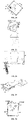
- the first hinge part 31 and the first fitting part 41 move relatively to drive the door 20 to rotate in situ relative to the cabinet 10
- the first hinge part 31 and the first fitting part 41 then move relatively to drive the door 20 to move from the pivoting side P towards the accommodating chamber S
- the second fitting part 42 limits the second hinge part 32
- the second hinge part 32 is released from the limit of the second fitting part 42
- the first fitting part 41 limits the first hinge part 31
- the second hinge part 32 and the second fitting part 42 move relatively to drive the door 20 to continuously rotate in situ.
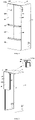
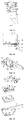
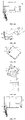
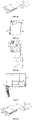
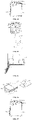
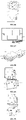
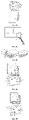
- FIGS. 1 to 5 schematic diagrams of a multi-door refrigerator 100 of the first embodiment of the present invention are shown.
- the refrigerator 100 may be configured as a single-door refrigerator having the first fitting portion 25 and the second fitting portion 12, or a side-by-side refrigerator, a multi-door refrigerator, or the like, having the first fitting portion 25 and the second fitting portion 12, in the present embodiment, the refrigerator 100 is a five-door refrigerator.
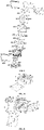
- the first switching part 401 and the second switching part 402 are fitted and connected with each other by a fifth shaft 50.
- the fifth shaft 50 includes a riveting post 51 and a riveting post gasket 52
- the riveting post 51 has a large end located below the second through hole 4024 and a small end sequentially extending into the second through hole 4024 and the first through hole 4014
- the riveting post gasket 52 is located above the first through hole 4014 and fitted with the riveting post 51 to lock the riveting post 51.
- the slots may be formed only in the second lining 4021 and the second sliding sheet 4022 to form the second through hole 4024; that is, the second through hole 4024 does not penetrate through the second bushing 4023, and at this point, the fifth shaft 50 extends from a position below the second bushing 4023 into the second through hole 4024 and the first through hole 4011, and the second bushing 4023 may shield the second through hole 4024 and the fifth shaft 50, thereby improving the attractiveness.
- the first decorative sheet 4015 is in an n shape; that is, the first decorative sheet 4015 covers only three side surfaces of the first switching part 401, so as to assemble the first decorative sheet 4015; the three side surfaces may be provided with snap structures to be fitted with the first decorative sheet 4015, and in a stacking direction of the first switching part 401 and the second switching part 402, a width of the first decorative sheet 4015 is substantially equal to a sum of thicknesses of the first lining 4011, the first sliding sheet 4012, and the first bushing 4013.
- the first switching part 401 and the second switching part 402 move relatively, such that the second hinge part 32 is released from the limit of the switching assembly 40, and the first shaft 311 and/or the second shaft 312 are/is limited at the locking sections 4132, 4142, 4152, 4162, such that the switching assembly 40 limits the first hinge part 31
- the switching assembly 40 and the second hinge part 32 move relatively, such that no mutual limit exists between the switching assembly 40 and the second hinge part 32, and the switching assembly 40 and the first hinge part 31 move relatively, such that the switching assembly 40 and the first hinge part 31 are limited by each other
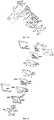
- the first shaft 311 is simultaneously limited at the first upper locking section 4132 and the first lower locking section 4142
- the second shaft 312 is simultaneously limited at the second upper locking section 4152 and the second lower locking section 4162
- the fourth shaft 322 is separated from the fourth limiting section 4222, which is described as follows.
- first switching part 401 and the second switching part 402 both rotate by certain angles, and the rotation angle of the second switching part 402 is greater than the rotation angle of the first switching part 401, such that the first switching part 401 and the second switching part 402 also move relatively to be staggered.
- the second shaft 312 is located at the second upper locking section 4152 and the second lower locking section 4162, since the first switching part 401 and the second switching part 402 are staggered, the second upper free section 4151 and the second lower free section 4161 which are originally overlapped with each other are also staggered, and at this point, the second upper free section 4151 and the second lower free section 4161 which are staggered restrict the second shaft 312 from being separated from the second upper locking section 4152 and the second lower locking section 4162, thus ensuring that the second shaft 312 is always kept at the second upper locking section 4152 and the second lower locking section 4162 in the process of continuously opening the door 20.
- the third shaft 321 located at the first switching part 401 and the fourth shaft 322 located at the second switching part 402 changes, the third shaft 321 is always located at the third free section 4211, and the fourth shaft 322 moves from the fourth limiting section 4222 to the fourth free section 4221; that is, the fourth shaft 322 is separated from the fourth limiting section 4222.
- the hinge assembly 30 further includes the second shaft 312 fitted with the first shaft 311 and the fourth shaft 322 fitted with the third shaft 321, and for simplicity of description, the door 20 is considered to rotate around the first shaft 311 first, and be then switched to rotated around the third shaft 321 by the switching assembly 40.
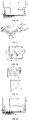
- the hinge assembly 30 is structurally different in different regions of the door 20, the above-mentioned hinge assembly 30 is located between an upper portion of the door 20 and the cabinet 10, and hereinafter, the hinge assembly 30' located between a lower portion of the door 20 and the cabinet 10 will be briefly described with reference to FIGS. 35 and 36 .
- the second hinge part 32' further includes an extension section 324' passing through the switching assembly 40' in a thickness direction, and the extension section 324' is connected to the hook 323', such that the hook 323' may be provided horizontally and fitted with the projection 313'.
- the refrigerator 100a is a side-by-side refrigerator 100a.
- a door 20a includes a first door 204aprovided corresponding to the first compartment S3 and a second door 205aprovided corresponding to the second compartment S4.
- the second hinge part 32a and the switching assembly 40a move relatively by a second shaft set 321a, 322a and a second groove set 421a, 422a which are fitted with each other;
- the second shaft set 321a, 322a includes a third shaft 321a and a fourth shaft 322a
- the second groove set 421a, 422a includes a third free section 421a, a fourth free section 4221a and a limiting section 4222a.
- the fourth shaft 322a is separated from the limiting section 4222a, and the first shaft 311a and/or the second shaft 312a are/is limited at the locking sections 4132a, 4142a, 4152a, 4162a, such that the switching assembly 40a limits the first hinge part 31a.
- the second hinge part 32b and the switching assembly 40b move relatively by a second shaft set 321b, 322b and a second groove set 421b, 422b which are fitted with each other;
- the second shaft set 321b, 322b includes a third shaft 321b and a fourth shaft 322b
- the second groove set 421b, 422b includes a third free section 421b, a fourth free section 4221b and a limiting section 4222b
- the third free section 421b includes a start position B1 and a pivoting position B2which are arranged oppositely
- the fourth free section 4221b includes a moving section M1 and a rotating section M2which are connected in sequence.
- first upper groove 413b is circular, and the first lower groove 414b is oval, but the present invention is not limited thereto.
- the bump 314b when the door 20b is in the closed state, the bump 314b is located in the recess 4016b, and the first limiting surface 3141b is apart from the second limiting surface 4017b;
- the door 20b drives the switching assembly 40b to move together relative to the first hinge part 31b, the bump 314b moves in the recess 4016b, and the first limiting surface 3141b and the second limiting surface 4017b gradually approach until the first limiting surface 3141b abuts against the second limiting surface 4017b; at this point, the first switching part 401b is unable to rotate relative to the first hinge part 31b; that is, the switching assembly 40b locks the first hinge part 31b, and a rotation angle of the door 20b when the first limiting surface 3141b abuts against the second limiting surface 4017b may be controlled by controlling sizes, shapes, or the like, of the bump 314b
- a second special-shaped groove 4043c is provided in a side of the second switching part 402c close to the first switching part 401c, the sixth elastic part 4042c and the sixth boss 4041c are limited in the second special-shaped groove 4043c, a second latching portion 4044c is provided on an inner wall of the second special-shaped groove 4043c, and a second ridge 4045c fitted with the second latching portion 4044c is provided on an outer wall of the sixth boss 4041c, such that the sixth boss 4041c may only move vertically relative to the second special-shaped groove 4043c under the action of the sixth elastic part 4042c; the sixth elastic part 4042c is configured as a spring, and an outer surface of the sixth boss 4041c is substantially configured as an arc surface.
- the first limiting surface 3141c abuts against the second limiting surface 4017c, such that the first switching part 401c can no longer move relative to the first hinge part 31c; and/or the third engaging portion 405c and the second engaging portion 316c are limited by each other, such that the first switching part 401c can no longer move relative to the first hinge part 31c; that is, the first hinge part 31c and the first switching part 401c are relatively stationary, and at this point, when the user continuously opens the door 20c, such that the door 20c is continuously opened from the first opening angle ⁇ 1 to the second opening angle ⁇ 2, since the fourth groove 422c is configured as an arc groove with the pivoting position C2of the third groove 421c as the circle center, the fourth shaft 322c does not move in the fourth groove 422c before the third shaft 321c moves to the pivoting position C2; that is, the second switching part 402c and the second hinge part 32c are relatively stationary,
- the through hole 4026c, the first lower groove 414c and the fifth groove 417c all have oval shapes and are parallel with one another; when the door 20c is continuously opened from the first opening angle ⁇ 1 to the second opening angle ⁇ 2, the second switching part 402c substantially translates relative to the first switching part 401c to drive the door 20c to translate relative to the cabinet 10c, but in other embodiments, the through hole 4026c, the first lower groove 414c, and the fifth groove 417c may have other shapes; for example, the through hole 4026c, the first lower groove 414c and the fifth groove 417c have arc shapes, the second switching part 402c rotates relative to the first switching part 401c to drive the door 20c to rotate relative to the cabinet 10c, and the door 20c moves a distance from the pivoting side P to the accommodating chamber S during the rotation.
- the second switching part 402c moves relative to the first switching part 401c to drive the sixth engaging portion 404c to be disengaged from the fourth engaging portion 4031c, and then, a bottom surface of the first switching part 401c close to the second switching part 402c abuts against the sixth boss 4041c to drive the sixth elastic part 4041c to be compressed, and when the sixth boss 4041c contacts the fifth engaging portion 4032c, the sixth elastic part 4041c resets to drive the sixth boss 4041c to enter the fifth engaging portion 4032c.
- the first switching part 401c and the second switching part 402c are mutually limited by means of the sixth engaging portion 404c and the fifth engaging portion 4032c, an acting force required for the sixth engaging portion 404c to disengage from the fifth engaging portion 4032c serves as a first acting force
- the first switching part 401c and the first hinge part 31c are mutually limited by means of the third engaging portion 405c and the second engaging portion 316c
- an acting force required for the third engaging portion 405c to disengage from the second engaging portion 316c serves as a second acting force
- the first acting force and the second acting force may be controlled by a structural arrangement, and preferably, the first acting force is smaller than the second acting force, such that in the closing process of the door 20c, the second switching part 402c and the first switching part 401c reset first, and then, the first switching part 401c and the first hinge part 31c reset; certainly, in other embodiments, the reset
- the fifth pitch exists between a center of the third shaft 321c and the front wall 21c, when the door 20c is continuously opened from the first opening angle ⁇ 1 to the second opening angle ⁇ 2, the fifth pitch is increased; here, the change of the fifth pitch is reflected in the movement of the door 20c by a distance away from the front end surface 103cof the cabinet 10c, thus, when the door 20cis provided with door gaskets on the side close to the cabinet 10c, it can prevent the door 20c from squeezing the door gaskets during opening, thus avoiding damage to the door gaskets and improving the sealing effect of the door gaskets, in other embodiments, of course, the fifth pitch may also kept unchanged.
- the first shaft 311c and the third shaft 321c are staggered, and thus, the refrigerator may be suitable for the embedded cupboard or the scenario with a small space for accommodating the refrigerator 100c.
- the wiring module 60 includes a fixed end 61 and a free end 62 which are provided oppositely, the fixed end 61 is connected to the door 20, the free end 62 is movably provided at the cabinet 10, and wiring E of the cabinet 10 sequentially passes through the free end 62 and the fixed end 61 and extends to the door 20.
- the refrigerator 100 further includes a limiting space 101, the limiting space 101 includes a notch 1011 provided towards the door 20, the fixed end 61 of the wiring module 60 passes through the notch 1011 to be connected to the door 20, and when the door 20 is in the opening process, the door 20 drives the wiring module 60 to move in the limiting space 101, and the free end 62 is always located in the limiting space 101.
- the limiting space 101 is located at a top 11 of the cabinet 10, the wiring module 60 is provided parallel to the top 11 of the cabinet 10, and the fixed end 61 is movably connected to the door 20; certainly, the limiting space 101 may be provided in other regions.
- the first hinge part 31 is fixed at the edge of the top 11, and in order to adapt to the design of the door 20 protruding from the top 11, the first hinge part 31 of the hinge assembly 30 has a substantial Z shape, such that the first hinge part 31 may extend from the top 11 of the cabinet 10 to a top of the door 20 to be fitted with the switching assembly 40 at the top of the door 20;
- the plurality of protrusions 112 include a first protrusion 1121 between the first hinge part 31 and the wiring module 60 and a second protrusion 1122 spaced apart from the first protrusion 1121, the first protrusion 1121 may prevent the wiring module 60 from interfering with the first hinge part 31, a profile of the first protrusion 1121 adapts to the motion track of the wiring module 60, and the second protrusions 1122 may be configured as a plurality of convex posts to reduce an impact between the wiring module 60 and the second protrusions 1122.
- the notch 1011 of the limiting space 101 has a first notch width
- the wiring module 60 includes a movable portion 63 located between the fixed end 61 and the free end 62, and the first notch width is greater than a maximum width of the movable portion 63.
- the movable portion 63 gradually protrudes from the limiting space 101; the first notch width is greater than the maximum width of the movable portion 63, so as to prevent the notch 1011 from limiting the protrusion of the movable portion 63 from the limiting space 101; the notch 1011 may control the motion track of the wiring module 60 to a certain extent, thereby avoiding that the wiring module 60 is separated from the limiting space 101 due to an excessively large motion amplitude.
Landscapes
- Engineering & Computer Science (AREA)
- Mechanical Engineering (AREA)
- Chemical & Material Sciences (AREA)
- Combustion & Propulsion (AREA)
- Physics & Mathematics (AREA)
- Thermal Sciences (AREA)
- General Engineering & Computer Science (AREA)
- Refrigerator Housings (AREA)
- Hinge Accessories (AREA)
- Devices That Are Associated With Refrigeration Equipment (AREA)
Applications Claiming Priority (7)
| Application Number | Priority Date | Filing Date | Title |
|---|---|---|---|
| CN201910804444 | 2019-08-28 | ||
| CN201910803434.8A CN112444072B (zh) | 2019-08-28 | 2019-08-28 | 嵌入式冰箱 |
| CN201910803437.1A CN112444073B (zh) | 2019-08-28 | 2019-08-28 | 嵌入式多门冰箱 |
| CN201910803425.9A CN112444068B (zh) | 2019-08-28 | 2019-08-28 | 嵌入式对开门冰箱 |
| CN202010179561.8A CN112444092B (zh) | 2019-08-28 | 2020-03-16 | 嵌入式冰箱 |
| CN202010637425.9A CN113882769B (zh) | 2020-07-03 | 2020-07-03 | 门体旋转轴可变的嵌入式冰箱 |
| PCT/CN2020/111633 WO2021037117A1 (zh) | 2019-08-28 | 2020-08-27 | 嵌入式冰箱 |
Publications (2)
| Publication Number | Publication Date |
|---|---|
| EP4023975A1 true EP4023975A1 (de) | 2022-07-06 |
| EP4023975A4 EP4023975A4 (de) | 2022-10-19 |
Family
ID=74684587
Family Applications (1)
| Application Number | Title | Priority Date | Filing Date |
|---|---|---|---|
| EP20856322.1A Pending EP4023975A4 (de) | 2019-08-28 | 2020-08-27 | Eingebetteter kühlschrank |
Country Status (5)
| Country | Link |
|---|---|
| US (1) | US12061040B2 (de) |
| EP (1) | EP4023975A4 (de) |
| JP (1) | JP7526785B2 (de) |
| AU (1) | AU2020339538B2 (de) |
| WO (1) | WO2021037117A1 (de) |
Families Citing this family (7)
| Publication number | Priority date | Publication date | Assignee | Title |
|---|---|---|---|---|
| CN114961484B (zh) * | 2019-07-23 | 2023-11-14 | 青岛海尔电冰箱有限公司 | 铰链组件及具有其的制冷设备 |
| CN115807605A (zh) * | 2021-09-15 | 2023-03-17 | 青岛海尔电冰箱有限公司 | 铰链及具有该铰链的嵌入式冰箱 |
| CN116067092A (zh) | 2021-10-29 | 2023-05-05 | 合肥美的电冰箱有限公司 | 一种箱体装置 |
| CN116067094A (zh) | 2021-10-29 | 2023-05-05 | 合肥美的电冰箱有限公司 | 一种箱体装置 |
| CN116067090A (zh) * | 2021-10-29 | 2023-05-05 | 合肥美的电冰箱有限公司 | 一种箱体装置 |
| CN116242088B (zh) * | 2023-03-16 | 2025-08-29 | 珠海格力电器股份有限公司 | 冰箱 |
| US20250354420A1 (en) * | 2024-05-17 | 2025-11-20 | Whirlpool Corporation | Household appliance |
Family Cites Families (54)
| Publication number | Priority date | Publication date | Assignee | Title |
|---|---|---|---|---|
| US1075130A (en) * | 1912-09-28 | 1913-10-07 | Edward L Ackerman | Concealed hinge. |
| US1832174A (en) * | 1930-06-24 | 1931-11-17 | Edward J Zahner | Frame with opening and closure therefor |
| US2793387A (en) * | 1955-08-22 | 1957-05-28 | Albert W Odell | Pivotal connection |
| US2867839A (en) | 1957-10-17 | 1959-01-13 | Midwest Mfg Corp | Door hinge |
| US3001225A (en) * | 1958-01-10 | 1961-09-26 | Admiral Corp | Dual pivot freezer hinge |
| US3083403A (en) | 1959-04-23 | 1963-04-02 | Jervis Corp | Hidden hinge structure |
| US3065498A (en) | 1959-12-11 | 1962-11-27 | Jervis Corp | Hinge device |
| US3201821A (en) | 1963-04-01 | 1965-08-24 | Niles L Ruckstuhl | Hinge |
| AU431315B2 (en) * | 1966-08-31 | 1972-12-28 | Improvements in and relating to windows and hinges therefor | |
| US4151681A (en) | 1977-12-01 | 1979-05-01 | General Electric Company | Arrangement for mounting hinge pin sockets to cabinet doors |
| JPS5948578A (ja) * | 1982-09-14 | 1984-03-19 | 株式会社東芝 | 貯蔵庫の扉枢支装置 |
| US5265954A (en) | 1989-02-21 | 1993-11-30 | Whirlpool Corporation | Refrigerator door hinge assembly |
| US5158503A (en) * | 1990-11-21 | 1992-10-27 | White Consolidated Industries, Inc. | Double-pivot door hinge for appliance doors |
| JP3143246B2 (ja) * | 1992-12-28 | 2001-03-07 | 三洋電機株式会社 | 業務用冷蔵庫 |
| JP2000018812A (ja) | 1998-06-24 | 2000-01-18 | Toshiba Corp | 冷蔵庫の扉開閉検知装置 |
| KR100443983B1 (ko) * | 2002-01-15 | 2004-08-09 | 삼성전자주식회사 | 냉장고 |
| JP3756909B2 (ja) | 2003-11-14 | 2006-03-22 | 均 西谷 | ヒンジ装置 |
| JP2005299314A (ja) | 2004-04-15 | 2005-10-27 | Matsushita Electric Ind Co Ltd | 冷蔵庫の扉開閉装置 |
| US8408664B2 (en) | 2005-03-16 | 2013-04-02 | Lg Electronics Inc. | Damper embedded in a home bar door of a refrigerator and method for manufacturing same |
| DE102006025815B4 (de) | 2006-06-02 | 2013-09-26 | Bayerische Motoren Werke Aktiengesellschaft | Mehrgelenk-Scharnier für eine Tür oder Klappe eines Kraftfahrzeugs |
| GB2439328B (en) * | 2006-06-22 | 2012-07-04 | Panasonic Mfg Uk Ltd | Domestic appliance with concealed hinge |
| JP5294189B2 (ja) | 2007-11-05 | 2013-09-18 | コクヨ株式会社 | 収納装置、ヒンジ装置、及びカバー体 |
| CN201155900Y (zh) | 2008-01-24 | 2008-11-26 | 李吉德 | 带紧门机构的冰箱 |
| JP5372432B2 (ja) * | 2008-08-21 | 2013-12-18 | 三洋電機株式会社 | 低温ショーケース |
| KR101519144B1 (ko) | 2008-11-14 | 2015-05-11 | 엘지전자 주식회사 | 냉장고 |
| KR20100107161A (ko) | 2009-03-25 | 2010-10-05 | 엘지전자 주식회사 | 냉장고 및 냉장고의 조립 방법 |
| DE102011116573B4 (de) | 2010-10-26 | 2017-10-19 | Heitek Heine Gmbh | Scharnier |
| JP5753379B2 (ja) | 2010-12-25 | 2015-07-22 | ハイアールアジア株式会社 | 冷却貯蔵庫の扉装置 |
| CN102062510B (zh) | 2011-01-25 | 2013-03-13 | 海信容声(广东)冰箱有限公司 | 一种嵌入式冰箱门铰链 |
| CN201954901U (zh) | 2011-01-25 | 2011-08-31 | 海信容声(广东)冰箱有限公司 | 一种嵌入式冰箱门铰链 |
| JP5313300B2 (ja) | 2011-06-24 | 2013-10-09 | タキゲン製造株式会社 | 筐体のせり出し回転型ヒンジ装置 |
| JP5976296B2 (ja) * | 2011-10-24 | 2016-08-23 | パナソニック株式会社 | 扉の取付構造及び取付方法 |
| JP6062164B2 (ja) * | 2012-06-13 | 2017-01-18 | 西谷 均 | ヒンジ装置 |
| JP5467139B1 (ja) * | 2012-11-08 | 2014-04-09 | 日本車輌製造株式会社 | 折りたたみ式テーブル |
| JP2015135228A (ja) * | 2013-10-17 | 2015-07-27 | 三星電子株式会社Samsung Electronics Co.,Ltd. | ヒンジ装置、及び該ヒンジ装置を備えた冷却貯蔵庫 |
| KR101622008B1 (ko) * | 2013-11-21 | 2016-05-17 | 동부대우전자 주식회사 | 냉장고용 중앙 격벽 밀착구조 및 이를 구비한 냉장고 |
| EP2960411B1 (de) | 2014-06-26 | 2019-08-21 | VKR Holding A/S | Dachfenster zur Rauchentlüftung |
| CN104265103B (zh) | 2014-09-18 | 2016-08-17 | 广东美的厨房电器制造有限公司 | 铰链和家用器具 |
| CN105546911B (zh) | 2015-12-21 | 2018-04-20 | 青岛海尔股份有限公司 | 冰箱 |
| CN105588398A (zh) | 2015-12-29 | 2016-05-18 | 青岛海尔股份有限公司 | 一种用于冰箱门体的铰链组件及冰箱 |
| CN106196819A (zh) * | 2016-08-05 | 2016-12-07 | 青岛海尔股份有限公司 | 冰箱 |
| CN206600959U (zh) | 2017-02-08 | 2017-10-31 | 青岛海尔股份有限公司 | 对开门冰箱及其竖梁 |
| CN108468488B (zh) | 2017-02-23 | 2021-02-02 | 青岛海尔模具有限公司 | 一种铰链组件及安装有该铰链组件的器具 |
| CN112878831B (zh) | 2017-03-31 | 2024-07-12 | 青岛海尔模具有限公司 | 一种铰链组件及安装有该铰链组件的器具 |
| CN107630610B (zh) | 2017-09-01 | 2019-08-02 | 青岛海尔股份有限公司 | 一种铰链组件及包括其的冰箱 |
| US9995528B1 (en) * | 2017-10-12 | 2018-06-12 | Whirlpool Corporation | Refrigerator having a camera selectively enclosed by a rotating mullion assembly |
| CN107883661A (zh) | 2017-11-09 | 2018-04-06 | 合肥雪祺电气有限公司 | 一种冰箱门体转角限位器及自由嵌入式冰箱 |
| CN107883662A (zh) | 2017-11-09 | 2018-04-06 | 合肥雪祺电气有限公司 | 一种冰箱铰链隐藏装置及自由嵌入式冰箱 |
| CN108286860B (zh) * | 2017-12-12 | 2020-09-29 | 青岛海尔股份有限公司 | 冰箱 |
| CN108302856B (zh) | 2017-12-12 | 2020-09-29 | 青岛海尔股份有限公司 | 冰箱 |
| CN108106312B (zh) * | 2017-12-12 | 2020-08-28 | 青岛海尔股份有限公司 | 冰箱 |
| CN108253711B (zh) | 2017-12-12 | 2020-09-29 | 青岛海尔股份有限公司 | 冰箱 |
| CN208605065U (zh) | 2018-06-30 | 2019-03-15 | 江苏星徽精密科技有限公司 | 一种具有敞开自由状态功能的嵌入式冰箱铰链 |
| CN108868422B (zh) | 2018-06-30 | 2023-10-10 | 江苏玖星精密科技集团有限公司 | 一种不带悬停的嵌入式冰箱缓冲铰链 |
-
2020
- 2020-08-27 EP EP20856322.1A patent/EP4023975A4/de active Pending
- 2020-08-27 US US17/638,805 patent/US12061040B2/en active Active
- 2020-08-27 JP JP2022513886A patent/JP7526785B2/ja active Active
- 2020-08-27 WO PCT/CN2020/111633 patent/WO2021037117A1/zh not_active Ceased
- 2020-08-27 AU AU2020339538A patent/AU2020339538B2/en active Active
Also Published As
| Publication number | Publication date |
|---|---|
| NZ785657A (en) | 2024-04-26 |
| US12061040B2 (en) | 2024-08-13 |
| WO2021037117A1 (zh) | 2021-03-04 |
| AU2020339538B2 (en) | 2023-06-01 |
| EP4023975A4 (de) | 2022-10-19 |
| JP2022546510A (ja) | 2022-11-04 |
| JP7526785B2 (ja) | 2024-08-01 |
| US20220325940A1 (en) | 2022-10-13 |
| AU2020339538A1 (en) | 2022-03-24 |
Similar Documents
| Publication | Publication Date | Title |
|---|---|---|
| EP4023964A1 (de) | Eingebetteter kühlschrank, der das öffnen der tür erleichtert | |
| EP4023975A1 (de) | Eingebetteter kühlschrank | |
| US12038226B2 (en) | Free embedded refrigerator | |
| EP4023977A1 (de) | Freier einbaukühlschrank mit erhöhtem öffnungsgrad | |
| US12055336B2 (en) | Refrigerator with switchable hinge assembly | |
| AU2020335813B2 (en) | Embedded refrigerator having switching assembly | |
| CN114876300B (zh) | 铰链组件及具有其的制冷装置 | |
| CN115126367B (zh) | 铰链组件及具有其的冰箱 | |
| CN115405180B (zh) | 铰链组件及具有其的家用电器 | |
| CN112444088B (zh) | 带有铰链组件的冰箱 | |
| CN115012753B (zh) | 铰链组件及具有其的制冷器具 | |
| CN115110860B (zh) | 铰链组件及具有其的冰箱 | |
| CN115045579B (zh) | 铰链组件及具有其的制冷电器 | |
| CN115110861B (zh) | 铰链组件及具有其的家用电器 | |
| CN114837508B (zh) | 铰链组件及具有其的制冷设备 | |
| WO2021037103A1 (zh) | 带有切换组件的冰箱 | |
| CN114857846B (zh) | 铰链组件及具有其的家用电器 | |
| WO2021037123A1 (zh) | 可实现重心内移的嵌入式冰箱 |
Legal Events
| Date | Code | Title | Description |
|---|---|---|---|
| STAA | Information on the status of an ep patent application or granted ep patent |
Free format text: STATUS: THE INTERNATIONAL PUBLICATION HAS BEEN MADE |
|
| PUAI | Public reference made under article 153(3) epc to a published international application that has entered the european phase |
Free format text: ORIGINAL CODE: 0009012 |
|
| STAA | Information on the status of an ep patent application or granted ep patent |
Free format text: STATUS: REQUEST FOR EXAMINATION WAS MADE |
|
| 17P | Request for examination filed |
Effective date: 20220315 |
|
| AK | Designated contracting states |
Kind code of ref document: A1 Designated state(s): AL AT BE BG CH CY CZ DE DK EE ES FI FR GB GR HR HU IE IS IT LI LT LU LV MC MK MT NL NO PL PT RO RS SE SI SK SM TR |
|
| A4 | Supplementary search report drawn up and despatched |
Effective date: 20220916 |
|
| RIC1 | Information provided on ipc code assigned before grant |
Ipc: E05D 7/085 20060101ALI20220912BHEP Ipc: F25D 23/02 20060101AFI20220912BHEP |
|
| DAV | Request for validation of the european patent (deleted) | ||
| DAX | Request for extension of the european patent (deleted) | ||
| STAA | Information on the status of an ep patent application or granted ep patent |
Free format text: STATUS: EXAMINATION IS IN PROGRESS |
|
| 17Q | First examination report despatched |
Effective date: 20240723 |
|
| GRAP | Despatch of communication of intention to grant a patent |
Free format text: ORIGINAL CODE: EPIDOSNIGR1 |
|
| STAA | Information on the status of an ep patent application or granted ep patent |
Free format text: STATUS: GRANT OF PATENT IS INTENDED |
|
| INTG | Intention to grant announced |
Effective date: 20260223 |