EP4023944B1 - Gerätetürscharnieranordnung - Google Patents
Gerätetürscharnieranordnung Download PDFInfo
- Publication number
- EP4023944B1 EP4023944B1 EP21217475.9A EP21217475A EP4023944B1 EP 4023944 B1 EP4023944 B1 EP 4023944B1 EP 21217475 A EP21217475 A EP 21217475A EP 4023944 B1 EP4023944 B1 EP 4023944B1
- Authority
- EP
- European Patent Office
- Prior art keywords
- hinge
- door
- appliance
- hinge arm
- latch cam
- Prior art date
- Legal status (The legal status is an assumption and is not a legal conclusion. Google has not performed a legal analysis and makes no representation as to the accuracy of the status listed.)
- Active
Links
Images


Classifications
-
- F—MECHANICAL ENGINEERING; LIGHTING; HEATING; WEAPONS; BLASTING
- F24—HEATING; RANGES; VENTILATING
- F24C—DOMESTIC STOVES OR RANGES ; DETAILS OF DOMESTIC STOVES OR RANGES, OF GENERAL APPLICATION
- F24C15/00—Details
- F24C15/02—Doors specially adapted for stoves or ranges
- F24C15/023—Mounting of doors, e.g. hinges, counterbalancing
-
- E—FIXED CONSTRUCTIONS
- E05—LOCKS; KEYS; WINDOW OR DOOR FITTINGS; SAFES
- E05D—HINGES OR SUSPENSION DEVICES FOR DOORS, WINDOWS OR WINGS
- E05D7/00—Hinges or pivots of special construction
- E05D7/10—Hinges or pivots of special construction to allow easy separation or connection of the parts at the hinge axis
-
- E—FIXED CONSTRUCTIONS
- E05—LOCKS; KEYS; WINDOW OR DOOR FITTINGS; SAFES
- E05D—HINGES OR SUSPENSION DEVICES FOR DOORS, WINDOWS OR WINGS
- E05D7/00—Hinges or pivots of special construction
- E05D7/12—Hinges or pivots of special construction to allow easy detachment of the hinge from the wing or the frame
-
- E—FIXED CONSTRUCTIONS
- E05—LOCKS; KEYS; WINDOW OR DOOR FITTINGS; SAFES
- E05Y—INDEXING SCHEME ASSOCIATED WITH SUBCLASSES E05D AND E05F, RELATING TO CONSTRUCTION ELEMENTS, ELECTRIC CONTROL, POWER SUPPLY, POWER SIGNAL OR TRANSMISSION, USER INTERFACES, MOUNTING OR COUPLING, DETAILS, ACCESSORIES, AUXILIARY OPERATIONS NOT OTHERWISE PROVIDED FOR, APPLICATION THEREOF
- E05Y2900/00—Application of doors, windows, wings or fittings thereof
- E05Y2900/30—Application of doors, windows, wings or fittings thereof for domestic appliances
- E05Y2900/308—Application of doors, windows, wings or fittings thereof for domestic appliances for ovens
Definitions
- the present disclosure generally relates to an appliance with a door and with a hinge assembly for said appliance door.
- Hinge assemblies are used on appliances to couple doors with cabinets. Often these hinge assemblies have various coupling assemblies for coupling components of the hinge assembly with a body of the appliance and/or the door.
- an adjustable appliance hinge receiver includes a base including spaced-apart first and second lateral walls.
- a slide body is slidably connected to the base and located between the lateral walls. The slide body slides relative to the base along an adjustment axis.
- At least one hinge mounting structure is connected to the slide body and is adapted to be engaged by an associated hinge.
- An adjustment system includes a first inclined ramp connected to the slide body and an adjustment shaft that extends between and that is rotatably supported by the first and second lateral walls of the base. The adjustment shaft is rotatable relative to the base about an axis of rotation.
- the adjustment system also includes an adjustment member engaged with the adjustment shaft and selectively movable along the axis of rotation in opposite first and second directions in response to rotational movement of the adjustment shaft in opposite first and second rotational directions such that rotation of the adjustment shaft in one of the first and second rotational directions causes the adjustment member to bear against the first ramp and induce sliding movement of the slide body relative to the base along the adjustment axis.
- a hinge assembly includes a claw and a body pivotally connected to the claw and movable to and between a first operative position and a second operative position.
- a link assembly operably interconnects the claw and the body.
- the link assembly includes at least one link pivotally connected to the claw and a spring connected between the link and an anchor point.
- a latch is movably connected to the claw, and the latch is movable to and between a locked position where it is adapted to engage an associated mounting receptacle to prevent separation of the claw from the mounting receptacle, and an unlocked position.
- the hinge assembly can be provided as part of a door mounting system that also includes a mating mounting receptacle.
- a hinge assembly for an associated appliance door includes an arm and a lever pivotally connected to the arm.
- the lever and arm are adapted to pivot relative to each other about a main pivot axis between a first position that corresponds to a closed position of the associated appliance door and a second position that corresponds to an opened position of the associated appliance door.
- a slide link is located adjacent the lever.
- a damper engagement structure is connected to the slide link.
- a biasing system urges the arm and lever toward the first position.
- a damper system includes a damper that damps pivoting movement between the arm and the lever for at least part of the movement between the arm and the lever when the arm and lever pivot relative to each other from the first position toward the second position.
- Document US9,404,299B2 discloses a home appliance having an adjustable door and including an appliance body defining a cavity therein, defining an access opening to the cavity and carrying the door, with the door being movable between a generally vertical covering relationship with the access opening and a generally horizontal open relationship with the access opening; and at least one hinge assembly operatively associated with the door, the hinge assembly including an adjustable hinge receiver and a claw mounted to the hinge receiver and the door to extend therebetween, the hinge receiver including an adjustment assembly operatively connected to the claw for at least one of raising the door and lowering the door with respect to the appliance body, the adjustment assembly including a user-accessible adjustment member, wherein the adjustment member and the claw are in general vertical alignment and the adjustment member is disposed above the claw.
- the present illustrated embodiments reside primarily in combinations apparatus components related to a hinge assembly for an appliance door. Accordingly, the apparatus components have been represented, where appropriate, by conventional symbols in the drawings, showing only those specific details that are pertinent to understanding the embodiments of the present disclosure so as not to obscure the disclosure with details that will be readily apparent to those of ordinary skill in the art having the benefit of the description herein. Further, like numerals in the description and drawings represent like elements.
- the terms “upper,” “lower,” “right,” “left,” “rear,” “front,” “vertical,” “horizontal,” and derivatives thereof shall relate to the disclosure as oriented in FIG. 1 .
- the term “front” shall refer to the surface of the element closer to an intended viewer, and the term “rear” shall refer to the surface of the element further from the intended viewer.
- reference numeral 10 generally designates an appliance including an appliance body 12.
- the appliance body 12 includes a front panel 14 defining a connector slot 16.
- a hinge receiver 18 is coupled with the appliance body 12 and has first and second opposing side walls 20, 22. The first and second side walls 20, 22 define a receiving space 24 therebetween.
- the hinge receiver 18 includes a first striker 28 positioned above a second striker 30, and the first and second strikers 28, 30 are aligned with the connector slot 16.
- a hinge arm assembly 34 includes a hinge arm 36 configured to engage with the second striker 30.
- a latch cam 38 is hingedly coupled with the hinge arm 36 and is movable between an engaged position and a disengaged position.
- a top surface 40 of the latch cam 38 contacts the first striker 28 when the latch cam 38 is in the engaged position.
- a door 44 is rotatably coupled with the appliance body 12 by the hinge receiver 18 and the hinge arm assembly 34. The door 44 is rotatable about a door axis X and movable between open and closed positions.
- the appliance 10 is illustrated including the appliance body 12 with a liner 48 defining a cavity 50.
- the liner 48 is coupled with the front panel 14 of the appliance body 12, and the front panel 14 defines an access opening 54 in communication with the cavity 50.
- the front panel 14 further defines a pair of connector slots 16 positioned on opposing sides of the opening 54.
- Each connector slot 16 may be elongated and may extend parallel to side walls of the liner 48.
- Each connector slot 16 is configured to at least partially receive one of a pair of hinge assemblies 60, as discussed in more detail elsewhere herein.
- the appliance body 12 may further include components typically found in a conventional cooking oven, such as an outer casing, electrical components, heating elements, gas lines, valves, control units, burner elements, broiled elements, and the like. Such components will not be described further herein except where necessary for a complete understanding of the aspects of the present disclosure.
- an exemplary form of the door 44 is illustrated configured to be coupled with the appliance body 12 by a pair of hinge assemblies 60.
- the door 44 is configured to selectively seal the cavity 50 and is movable between open and closed positions. When the door 44 is in the open position, the cavity 50 is accessible through the opening 54 defined by a front panel 14 of the appliance body 12.
- the door 44 includes a front door panel 68 and a rear door panel 70 in a spaced apart configuration to define a space therebetween.
- a handle 66 is coupled with the front door panel 68 and configured to move the door 44 between the open position and the closed position. It will be understood that the door 44 may include any number of panels without departing from the scope of the present disclosure.
- door 44 is illustrated as being configured to be coupled to the appliance body 12 by a pair of hinge assemblies 60, for the remainder of the disclosure, only one of the hinge assemblies 60 is described in detail, and it will be further understood that each of the pair of hinge assemblies 60 is formed in the same or a similar way with the same components.
- the hinge assembly 60 includes a hinge receiver 18 and a hinge arm assembly 34.
- the hinge receiver 18 is positioned proximate the respective connector slot 16 and is configured to be engaged with the hinge arm assembly 34 to operably couple the door 44 with the appliance body 12.
- the hinge arm assembly 34 is coupled with the door 44 and includes the hinge arm 36 configured to be engaged with the respective hinge receiver 18 and the latch cam 38 configured to be positioned within and/or through the connector slot 16.
- the hinge receiver 18 is coupled with the front panel 14 and is positioned to at least partially align with the connector slot 16.
- the hinge receiver 18 is generally elongated and includes first and second side walls 20, 22 positioned on opposing sides of the respective connector slot 16.
- the first and second side walls 20, 22 define a receiving space 24 therebetween configured to be in communication with the connector slot 16 and at least partially receive the hinge arm 36 of the hinge arm assembly 34.
- the hinge receiver 18 may include a front wall 72 extending between the first and second side walls 20, 22.
- the front wall 72 may be integrally formed with one or both of the first and second side walls 20, 22.
- the front wall 72 includes an upper portion 74 located at a top of the hinge receiver 18, a central portion 76, and a lower portion 78 located at bottom portion of the hinge receiver 18 and spaced apart from the central portion 76.
- Each of the upper and lower portions 74, 78 may be configured to be coupled with the front panel 14 of the appliance body 12 by one or more fasteners 84.
- the front wall 72 may extend along the entirety of the length of the side walls 20, 22 or along a portion of the length of the side walls 20, 22.
- the upper portion 74 and/or the lower portion 78 may be integrally formed with the central portion 76.
- the upper portion 74 and/or the lower portion 78 may be spaced apart from the central portion 76.
- the first side wall 20 includes a protrusion 90 extending into the receiving space 24.
- the protrusion 90 is positioned proximate a front edge of the first side wall 20 and has a vertical portion 94 and an inclined portion 96.
- the vertical portion 94 is spaced apart from the side wall 20, and the inclined portion 96 is inclined inward from the side wall 20 toward the vertical portion 94.
- the protrusion 90 may be configured to at least partially retain the hinge arm 36 within the receiving space 24 of the hinge receiver 18 and/or guide engagement of the hinge arm 36 into engagement with the hinge receiver 18.
- each of the first and second side walls 20, 22 may include a respective protrusion 90.
- the protrusions 90 of the opposing side walls 20, 22 may be vertically aligned such that the width of the receiving space 24 defined between the first and second side walls 20, 22 is reduced between the protrusions 90.
- first and second strikers 28, 30 are coupled with and extend between the first and second side walls 20, 22 of the hinge receiver 18.
- the first striker 28 may be positioned above the protrusion 90 of the first side wall 20, and the second striker 30 may be positioned rearward of the first striker 28 and the protrusion 90.
- the second striker 30 is further positioned below the first striker 28 such that the first striker 28 is vertically and horizontally offset from the second striker 30. In other words, the first striker 28 is positioned forward and upward from the second striker 30.
- the hinge arm assembly 34 includes the hinge arm 36 and the latch cam 38 configured to engage with the hinge receiver 18.
- a hinge body 100 of the hinge arm assembly 34 is fixedly coupled with the door 44.
- the hinge body 100 may be coupled with one of the door panels 68, 70.
- the hinge body 100 may alternatively be coupled with a door support 104 between the door panels 68, 70 or along an edge of the door 44.
- the hinge body 100 is generally elongated and extends along a portion of the door 44 to rotate the door 44 between the open and closed positions. It is contemplated that the hinge body 100 may be at least partially positioned between the door panels 68, 70. It is further contemplated that the hinge body 100 may be integrally formed with the door support 104 or may be formed as the door support 104.
- the hinge body 100 is rotatably coupled with the hinge arm 36.
- the hinge arm 36 includes a door engagement portion 106.
- the door engagement portion 106 of the hinge arm 36 defines a door pin receiving well 108 configured to receive a door pin 110, as discussed in more detail elsewhere herein.
- the door pin 110 may be a fastener (e.g., a pin, a screw, a bolt, etc.) configured to couple the hinge body 100 with the hinge arm 36.
- the door axis X extends through a center of the door pin 110, as best shown in FIGS. 1 and 2 , such that rotation of the hinge body 100 about the door pin 110 moves the door 44 between the open and closed positions about the door axis X.
- the hinge arm 36 is configured to be received by the connector slot 16 and extend into the receiving space 24 of the hinge receiver 18.
- the hinge arm 36 includes a body 116 defining an aperture 118.
- the aperture 118 is configured to receive a pin 122 configured to couple the latch cam 38 with the hinge arm 36.
- the pin 122 is configured such that the latch cam 38 is movable relative to the hinge arm 36 between engaged and disengaged positions.
- the hinge arm 36 includes a door engagement portion 106 extending from one side of the body 116.
- the hinge arm 36 further includes a coupling flange 126 extending from the body 116 in a direction generally opposite that of the door engagement portion 106.
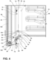
- the coupling flange 126 is configured to be inserted through the connector slot 16 and into the receiving space 24 of the hinge receiver 18 (see FIGS. 4 and 6 ).
- the coupling flange 126 defines a striker receiving space 134 configured to at least partially receive the second striker 30 of the hinge receiver 18, as described in more detail below.
- the coupling flange 126 is at least partially spaced apart from the body 116 of the hinge arm 36 by a slot 140.
- the hinge arm 36 defines a slot 140.
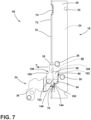
- the slot 140 is defined to extend vertically between the coupling flange 126 and the hinge arm 36 and is configured to receive a lower internal edge 144 of the front panel 14 when the hinge arm 36 is positioned through the connector slot 16 (see FIGS. 6 and 7 ).
- the engagement between the lower internal edge 144 and the slot 140 may be configured to increase the retention of the hinge arm 36 within the hinge receiver 18.
- the coupling flange 126 also includes a stop 150 extending outward from a side of the hinge arm 36.
- the stop 150 includes an abutment portion 158 and a tapered portion 160.
- the abutment portion 158 may be generally oblong or round or may have any other shape.
- the abutment portion 158 may be configured to be substantially planar or may be rounded.
- the tapered portion 160 extends from the abutment portion 158 toward the striker receiving space 134 and is tapered away from the abutment portion 158.
- the stop 150 may be shaped such that the tapered portion 160 is tapered inward toward a point and tapered downward from the abutment portion 158 to the surface of the hinge arm 36.
- the stop 150 is configured to abut the protrusion 90 of the hinge receiver 18 when the hinge arm 36 is engaged with the hinge receiver 18.
- the tapered portion 160 allows the stop 150 to be positioned to contact the vertical portion 94 of the protrusion 90 of the hinge receiver 18.
- the coupling flange 126 may have stops 150 on both sides of the hinge arm 36 such that the stops 150 engage with the protrusions 90 of each side wall 20, 22 of the hinge receiver 18.
- the latch cam 38 is rotatably coupled with the hinge arm 36 and includes a body portion 170 and a coupling portion 174.
- the coupling portion 174 extends from the body portion 170 and defines a receiving well 178.
- the receiving well 178 is aligned with the aperture 118 of the hinge arm 36.
- the aperture 118 and the receiving well 178 are configured to receive the pin 122 such that the latch cam 38 is rotatable about the pin 122 relative to the hinge arm 36.
- the coupling portion 174 may extend from the body portion 170 such that the coupling portion 174 and the body portion 170 define a space 182 configured to at least partially receive the protrusion 90 of the hinge receiver 18 and the stop 150 of the hinge arm 36 when the latch cam 38 is in the engaged position.
- the latch cam 38 further includes an upper edge 188 extending between a front edge 190 and a rear edge 192.
- the front edge 190 of the latch cam 38 extends along the body portion 170 and the coupling portion 174.
- the upper edge 188 includes the top surface 40 of the latch cam 38.
- the upper edge 188 may be non-linear such that the body portion 170 is more narrow proximate the rear edge 192 than proximate the front edge 190.
- material may be added to the latch cam 38 proximate the rear edge 192 to shift the center of gravity of the latch cam 38 to retain the latch cam 38 in the engaged position.
- the front edge 190 of the latch cam 38 further includes a tab 196 extending outward from the latch cam 38.
- the tab 196 defines a notch 198 configured to be used as a pull tab to move the latch cam 38 from the engaged position to the disengaged position to remove the hinge arm assembly 34 from engagement with the hinge receiver 18, as discussed in more detail elsewhere herein.
- the tab 196 may be generally rounded and may define the notch 198 to receiver a user's finger, a standard tool, or any other mechanism for applying a pulling force F (see FIG. 7 ) to the latch cam 38.
- the tab 196 of the latch cam 38 may further be configured to allow the latch cam 38 to be moved between the engaged and disengaged positions without a specialized tool.
- the hinge arm 36 is inserted into the receiving space 24 of the hinge receiver 18 proximate the first and second strikers 28, 30 (see arrow A).
- the coupling flange 126 is aligned with the second striker 30, and the striker receiving space 134 is configured to receive the second striker 30.
- FIGS. 6 and 7 when the coupling flange 126 is inserted into the receiving space 24, the lower internal edge of the hinge receiver 144 is received by the slot 140 and may be configured to retain the hinge arm 36 in engagement with the hinge receiver 18.
- the latch cam 38 is then rotated (see arrow B of FIG. 6 ) from the disengaged position ( FIG. 6 ) to the engaged position ( FIG. 7 ).
- the top surface 40 of the upper edge 188 is configured to abut the first striker 28.
- the top surface 40 of the upper edge 188 slides under the first striker 28.
- the engagement of the first striker 28 with the top surface 40 is configured to at least partially retain the latch cam 38 in the engaged position.
- the non-linear shape of the upper edge 188 and the top surface 40 of the latch cam 38 may further be configured to provide a self-guided engagement of the latch cam 38, and the hinge arm assembly 34, with the hinge receiver 18.
- the latch cam 38 may be configured to position a center of gravity of the latch cam 38 to maintain the engagement between the latch cam 38 and the hinge receiver 18 to prevent inadvertent release of the latch cam 38.
- the use of the hinge assembly 60 including the hinge receiver 18 and the hinge arm assembly 34 provides contact between the latch cam 38 and the first striker 28.
- the contact between the latch cam 38 and the first striker 28 may be configured to maintain engagement between the hinge receiver 18 and the hinge arm assembly 34.
- the contact may be configured to prevent lifting of the hinge arm 36 in the connector slot 16 when the door 44 is moved from the open position to the closed position.
- an appliance includes an appliance body having a front panel defining a connector slot.
- a hinge receiver is coupled with the appliance body and has opposing side walls defining a receiving space therebetween.
- the hinge receiver includes a first striker positioned above a second striker.
- the first and second strikers are aligned with the connector slot.
- a hinge arm assembly includes a hinge arm configured to engage with the second striker and a latch cam hingedly coupled with the hinge arm.
- the latch cam is movable between an engaged position and a disengaged position, and a top surface of the latch cam abuts the first striker in the engaged position.
- a door is rotatably coupled with the appliance body by the hinge receiver and the hinge assembly and is rotatable about a door axis between open and closed positions.
- the hinge arm includes a coupling flange extending from a body of the hinge arm in a direction generally opposite that of a door engagement portion of the hinge arm.
- the hinge receiver comprises a protrusion extending into the receiving space, wherein the protrusion is positioned proximate a front edge of one of the opposing side walls and has a vertical portion and an inclined portion.
- the coupling flange includes a stop extending outward from a side of the hinge arm, wherein the stop includes an abutment portion and a tapered portion. The stop is configured to abut the protrusion when the hinge arm is engaged with the hinge receiver and the tapered portion allows the stop to be positioned to contact the vertical portion of the protrusion.
- a first striker is offset from a second striker.
- a latch cam is weighted to prevent inadvertent movement of the latch cam from an engaged position to a disengaged position.
- a hinge body is coupled with a door and is rotatably coupled with a hinge arm by a fastener, and a door axis extends through the fastener.
- the hinge arm includes a door engagement portion that defines a door pin receiving well configured to receive the fastener.
- a latch cam includes a tab configured to receive a pulling force to move the latch cam from an engaged position to a disengaged position.
- a hinge receiver includes a lower internal edge proximate at least one of first and second strikers.
- a hinge arm defines a slot configured to receive a lower internal edge of a hinge receiver.
- At least a portion of the hinge arm assembly is received within the receiving space.
- the hinge body is generally elongated and extends along a portion of the door to rotate the door between the open and closed positions.
- an appliance includes an appliance body having a front panel defining a connector slot.
- a hinge receiver is coupled with the front panel and includes first and second strikers aligned with the connector slot. The first striker is positioned above and forward of the second striker.
- a door is coupled with the appliance body and is movable between open and closed positions.
- a hinge body is coupled with the door, and a hinge arm is coupled with the hinge body and configured to engage with the second striker.
- a latch cam is operably coupled with the hinge arm and is movable between an engaged position and a disengaged position. A top surface of the latch cam abuts the first striker in the engaged position.
- a latch cam includes a body having a front edge and a rear edge and is gravity biased toward the rear edge in an engaged position.
- a latch cam includes a tab configured to receive a pulling force to move the latch cam from an engaged position to a disengaged position.
- a hinge arm defines a slot configured to receive a lower internal edge of a hinge receiver.
- a hinge arm defines a receiving space configured to at least partially receive a second striker.
- a hinge arm includes a stop tapered toward a receiving space of the hinge arm.
- a hinge receiver includes a side wall having a protrusion configured to contact a stop when a second striker is received by a receiving space of a hinge arm.
- a hinge assembly for an appliance includes a hinge receiver including first and second strikers.
- the first striker is positioned above and forward of the second striker.
- a hinge arm defines a receiving space configured to receive the second striker.
- a hinge body is rotatably coupled with the hinge arm, and a latch cam is operably coupled with the hinge arm.
- the latch cam is movable between an engaged position and a disengaged position. A top surface of the latch cam abuts the first striker in the engaged position.
- a top surface of a latch cam extends along a non-linear upper edge.
- a latch cam includes a tab extending forward of the latch cam.
- a hinge arm includes a stop having a first portion tapered away from a second portion.
- a hinge receiver includes a side wall having a protrusion configured to contact a second portion of a stop when a second striker is received by a hinge arm.
- a hinge receiver is coupled with a front panel of an appliance body and is positioned to align first and second strikers with a connector opening of the front panel.
- the term "coupled” in all of its forms, couple, coupling, coupled, etc. generally means the joining of two components (electrical or mechanical) directly or indirectly to one another. Such joining may be stationary in nature or movable in nature. Such joining may be achieved with the two components (electrical or mechanical) and any additional intermediate members being integrally formed as a single unitary body with one another or with the two components. Such joining may be permanent in nature or may be removable or releasable in nature unless otherwise stated.
- elements shown as integrally formed may be constructed of multiple parts or elements shown as multiple parts may be integrally formed, the operation of the interfaces may be reversed or otherwise varied, the length or width of the structures and/or members, or connector, or other elements of the system may be varied, the nature or number of adjustment positions provided between the elements may be varied.
- the elements and/or assemblies of the system may be constructed from any of a wide variety of materials that provide sufficient strength or durability, in any of a wide variety of colors, textures, and combinations. Accordingly, all such modifications are intended to be included within the scope of the present invention, as defined in the appended claims.
Landscapes
- Engineering & Computer Science (AREA)
- Mechanical Engineering (AREA)
- Chemical & Material Sciences (AREA)
- Combustion & Propulsion (AREA)
- General Engineering & Computer Science (AREA)
- Hinges (AREA)
- Casings For Electric Apparatus (AREA)
Claims (10)
- Gerät (10), umfassend:einen Gerätekörper (12), der eine Frontplatte (14) beinhaltet, die einen Verbindungsschlitz (16) definiert;eine Scharnieraufnahme (18), die mit dem Gerätekörper (12) gekoppelt ist und gegenüberliegende Seitenwände (20, 22) aufweist, die einen Aufnahmeraum (24) dazwischen definieren, wobei die Scharnieraufnahme (18) einen ersten Schließer (28) beinhaltet, der oberhalb eines zweiten Schließers (30) positioniert ist, und der erste und der zweite Schließer (28, 30) mit dem Verbindungsschlitz (16) ausgerichtet sind;eine Scharnierarmanordnung (34), die einen Scharnierarm (36), der konfiguriert ist, mit dem zweiten Schließer (30) in Eingriff zu gelangen, und einen Verriegelungsnocken (38), der mit dem Scharnierarm (36) scharniermäßig gekoppelt ist, beinhaltet, wobei der Verriegelungsnocken (38) zwischen einer Eingriffsposition und einer Außereingriffsposition bewegbar ist und eine obere Fläche bzw. Oberfläche (40) des Verriegelungsnockens (38) in der Eingriffsposition an dem ersten Schließer (28) anliegt; undeine Tür (44), die durch die Scharnieraufnahme (18) und die Scharnierarmanordnung (34) drehbar mit dem Gerätekörper (12) gekoppelt ist, wobei die Tür (44) um eine Türachse (X) zwischen einer offenen und einer geschlossenen Position drehbar ist,wobei der Scharnierarm (36) einen Kopplungsflansch (126) beinhaltet, der sich von einem Körper (116) des Scharnierarms (36) in einer Richtung erstreckt, die im Allgemeinen der eines Türeingriffsabschnitts (106) des Scharnierarms (36) entgegengesetzt ist,dadurch gekennzeichnet, dass die Scharnieraufnahme umfassteinen Vorsprung (90), der sich in den Aufnahmeraum (24) erstreckt,wobei der Vorsprung (90) in der Nähe eines vorderen Rands bzw. einer vorderen Kante einer der gegenüberliegenden Seitenwände (20) positioniert ist und einen vertikalen Abschnitt (94) und einen geneigten Abschnitt (96) aufweist,wobei der Kopplungsflansch (126) einen Anschlag (150) beinhaltet, der sich von einer Seite des Scharnierarms (36) nach außen erstreckt,wobei der Anschlag (150) einen Anlageabschnitt (158) und einen verjüngten Abschnitt (160) beinhaltet,wobei der Anschlag (150) konfiguriert ist, an dem Vorsprung (90) anzuliegen, wenn der Scharnierarm (36) mit der Scharnieraufnahme (18) in Eingriff ist, undwobei der verjüngte Abschnitt (160) es dem Anschlag (150) ermöglicht, so positioniert zu werden, dass er den vertikalen Abschnitt (94) des Vorsprungs (90) kontaktiert.
- Gerät (10) nach Anspruch 1, wobei der erste Schließer (28) zu dem zweiten Schließer (30) versetzt ist.
- Gerät (10) nach einem der Ansprüche 1 oder 2, wobei der Verriegelungsnocken (38) beschwert ist, um eine unbeabsichtigte Bewegung des Verriegelungsnockens (38) von der Eingriffsposition in die Außereingriffsposition zu verhindern.
- Gerät (10) nach einem der Ansprüche 1-3, wobei ein Scharnierkörper (100) mit der Tür (44) gekoppelt ist und durch ein Befestigungselement (110) drehbar mit dem Scharnierarm (36) gekoppelt ist, wobei sich die Türachse (X) durch das Befestigungselement (110) hindurch erstreckt.
- Gerät (10) nach Anspruch 4, wobei der Scharnierarm (36) einen Türeingriffsabschnitt (106) beinhaltet, der eine Türstiftaufnahmevertiefung (108) definiert, die konfiguriert ist, das Befestigungselement (110) aufzunehmen.
- Gerät (10) nach einem der Ansprüche 1-5, wobei der Verriegelungsnocken (38) eine Lasche bzw. Nase (196) beinhaltet, die konfiguriert ist, eine Zugkraft (F) aufzunehmen, um den Verriegelungsnocken (38) von der Eingriffsposition in die Außereingriffsposition zu bewegen.
- Gerät (10) nach einem der Ansprüche 1-6, wobei die Scharnieraufnahme (18) einen unteren Innenrand bzw. eine untere Innenkante (144) in der Nähe mindestens eines von dem ersten und dem zweiten Schließer (28, 30) beinhaltet.
- Gerät (10) nach Anspruch 7, wobei der Scharnierarm (36) einen Schlitz (140) definiert, der konfiguriert ist, die untere Innenkante (144) aufzunehmen.
- Gerät (10) nach einem der Ansprüche 1-8, wobei zumindest ein Abschnitt der Scharnierarmanordnung (34) innerhalb des Aufnahmeraums (24) aufgenommen ist.
- Gerät (10) nach Anspruch 4, wobei der Scharnierkörper (100) im Allgemeinen länglich ist und sich entlang eines Abschnitts der Tür (44) erstreckt, um die Tür (44) zwischen der offenen und der geschlossenen Position zu drehen.
Applications Claiming Priority (1)
| Application Number | Priority Date | Filing Date | Title |
|---|---|---|---|
| US17/139,327 US11377890B1 (en) | 2020-12-31 | 2020-12-31 | Appliance door hinge assembly |
Publications (2)
| Publication Number | Publication Date |
|---|---|
| EP4023944A1 EP4023944A1 (de) | 2022-07-06 |
| EP4023944B1 true EP4023944B1 (de) | 2024-10-09 |
Family
ID=79165088
Family Applications (1)
| Application Number | Title | Priority Date | Filing Date |
|---|---|---|---|
| EP21217475.9A Active EP4023944B1 (de) | 2020-12-31 | 2021-12-23 | Gerätetürscharnieranordnung |
Country Status (2)
| Country | Link |
|---|---|
| US (1) | US11377890B1 (de) |
| EP (1) | EP4023944B1 (de) |
Families Citing this family (3)
| Publication number | Priority date | Publication date | Assignee | Title |
|---|---|---|---|---|
| KR102040222B1 (ko) * | 2018-04-16 | 2019-11-04 | 엘지전자 주식회사 | 래치 모듈, 그 제어 방법 및 이를 적용한 조리기기 |
| WO2024111898A1 (ko) * | 2022-11-24 | 2024-05-30 | 삼성전자주식회사 | 조리기기 |
| US12546482B2 (en) * | 2023-10-17 | 2026-02-10 | Mansfield Engineered Components, LLC | Slow open hinge assembly |
Family Cites Families (23)
| Publication number | Priority date | Publication date | Assignee | Title |
|---|---|---|---|---|
| US4817240A (en) | 1983-06-03 | 1989-04-04 | Ace Manufacturing Co. | Appliance door hinge |
| US6035848A (en) * | 1998-07-01 | 2000-03-14 | Whirlpool Corporation | Oven and range door lock mechanism |
| IT1312037B1 (it) | 1999-03-30 | 2002-04-04 | Faringosi Hinges Srl | Cerniera perfezionata per mobili e simili con braccio mobile dispostoall'interno del braccio fisso. |
| US6397836B1 (en) | 2001-02-27 | 2002-06-04 | The Stanley Works | Damped oven door mounting assemblies |
| US7134169B2 (en) | 2004-01-15 | 2006-11-14 | Mansfield Assemblies Co. | Hinge assembly and door mounting system including same |
| US7275283B2 (en) | 2004-05-03 | 2007-10-02 | Keystone Friction Hinge Co. | Appliance hinge |
| KR100828274B1 (ko) | 2005-11-04 | 2008-05-07 | 풍원공업 주식회사 | 도어 힌지 |
| ITBO20070369A1 (it) * | 2007-05-23 | 2008-11-24 | Nuova Star Spa | Cerniera per ante o sportelli |
| KR100959211B1 (ko) | 2008-04-22 | 2010-05-19 | 풍원공업 주식회사 | 도어 잠금 장치 |
| US8201304B2 (en) * | 2009-02-25 | 2012-06-19 | General Electric Company | Compliant door hinge |
| US8266765B2 (en) * | 2009-03-11 | 2012-09-18 | Electrolux Home Products, Inc. | Appliance door hinge |
| US20100251521A1 (en) * | 2009-04-01 | 2010-10-07 | Electrolux Home Products, Inc. | Door hinge assembly |
| IT1395039B1 (it) * | 2009-08-13 | 2012-09-05 | Nuova Star Spa | Anta o sportello di elettrodomestici. |
| US9404299B2 (en) | 2012-05-02 | 2016-08-02 | Bsh Home Appliances Corporation | Home appliance with adjustable hinges |
| US9958166B2 (en) | 2012-05-31 | 2018-05-01 | Bsh Home Appliances Corporation | Household appliance having a latch retainer for an all glass inner door |
| US9347674B2 (en) | 2012-05-31 | 2016-05-24 | Bsh Home Appliances Corporation | Household appliance having a mounting system for door skin outer glass |
| US10145157B2 (en) * | 2013-01-31 | 2018-12-04 | Mansfield Engineered Components, Inc. | Breakaway hinge receptacle |
| KR101493165B1 (ko) * | 2013-09-11 | 2015-02-13 | 서원코리아 주식회사 | 도어 힌지 |
| SI24750A (sl) * | 2014-06-04 | 2015-12-31 | Turna D.O.O. | Zaklep zapaha za tečaj vrat |
| CN204960609U (zh) * | 2015-09-18 | 2016-01-13 | 刘明成 | 一种烤箱铰链 |
| US10082298B2 (en) | 2017-02-02 | 2018-09-25 | Mansfield Engineered Components, Inc. | Hinge assembly with slow close and optional slow open characteristics |
| US10890334B2 (en) * | 2017-02-02 | 2021-01-12 | Mansfield Engineered Components, Inc. | Hinge assembly with slow close and/or slow open characteristics |
| US11624223B2 (en) * | 2018-12-12 | 2023-04-11 | Mansfield Engineered Components, Inc. | Side-accessible adjustable receiver for appliance hinge |
-
2020
- 2020-12-31 US US17/139,327 patent/US11377890B1/en active Active
-
2021
- 2021-12-23 EP EP21217475.9A patent/EP4023944B1/de active Active
Also Published As
| Publication number | Publication date |
|---|---|
| US20220205295A1 (en) | 2022-06-30 |
| US11377890B1 (en) | 2022-07-05 |
| EP4023944A1 (de) | 2022-07-06 |
Similar Documents
| Publication | Publication Date | Title |
|---|---|---|
| EP4023944B1 (de) | Gerätetürscharnieranordnung | |
| US7934290B2 (en) | Door hinge device with fulcrum at variable position | |
| CN102459794A (zh) | 滑动和倾斜的门组件 | |
| US6035848A (en) | Oven and range door lock mechanism | |
| US7066503B2 (en) | Springless oven door latch assembly | |
| US10837652B2 (en) | Appliance secondary door | |
| US4287873A (en) | Oven door hinge | |
| US12281797B2 (en) | Hinge assembly for an appliance door | |
| KR20210090391A (ko) | 조리기기 | |
| US7134169B2 (en) | Hinge assembly and door mounting system including same | |
| US11029035B2 (en) | Oven | |
| JP2019209834A5 (de) | ||
| CN107131528A (zh) | 烹饪装置 | |
| CN116357170A (zh) | 一种防猫眼开锁的智能门锁 | |
| US11236536B1 (en) | Appliance door hinge assembly | |
| EP4426066A1 (de) | Kochgerät | |
| JP2727427B2 (ja) | スライドヒンジ | |
| KR101462181B1 (ko) | 전자레인지 | |
| CN116624028A (zh) | 烹饪器具的门组件和烹饪器具 | |
| KR20170127152A (ko) | 세탁기용 도어 힌지 | |
| EP1998117B1 (de) | BACKOFEN MIT EINER SCHLIEßVORRICHTUNG | |
| US20220106723A1 (en) | User-interface assembly for an appliance | |
| CN108433567B (zh) | 门体闭合机构及烹饪装置 | |
| CN223286952U (zh) | 烹饪器具 | |
| JP2794375B2 (ja) | 調理器のサービス扉 |
Legal Events
| Date | Code | Title | Description |
|---|---|---|---|
| PUAI | Public reference made under article 153(3) epc to a published international application that has entered the european phase |
Free format text: ORIGINAL CODE: 0009012 |
|
| STAA | Information on the status of an ep patent application or granted ep patent |
Free format text: STATUS: THE APPLICATION HAS BEEN PUBLISHED |
|
| AK | Designated contracting states |
Kind code of ref document: A1 Designated state(s): AL AT BE BG CH CY CZ DE DK EE ES FI FR GB GR HR HU IE IS IT LI LT LU LV MC MK MT NL NO PL PT RO RS SE SI SK SM TR |
|
| STAA | Information on the status of an ep patent application or granted ep patent |
Free format text: STATUS: REQUEST FOR EXAMINATION WAS MADE |
|
| 17P | Request for examination filed |
Effective date: 20230103 |
|
| RBV | Designated contracting states (corrected) |
Designated state(s): AL AT BE BG CH CY CZ DE DK EE ES FI FR GB GR HR HU IE IS IT LI LT LU LV MC MK MT NL NO PL PT RO RS SE SI SK SM TR |
|
| GRAP | Despatch of communication of intention to grant a patent |
Free format text: ORIGINAL CODE: EPIDOSNIGR1 |
|
| STAA | Information on the status of an ep patent application or granted ep patent |
Free format text: STATUS: GRANT OF PATENT IS INTENDED |
|
| INTG | Intention to grant announced |
Effective date: 20240429 |
|
| GRAS | Grant fee paid |
Free format text: ORIGINAL CODE: EPIDOSNIGR3 |
|
| GRAA | (expected) grant |
Free format text: ORIGINAL CODE: 0009210 |
|
| STAA | Information on the status of an ep patent application or granted ep patent |
Free format text: STATUS: THE PATENT HAS BEEN GRANTED |
|
| P01 | Opt-out of the competence of the unified patent court (upc) registered |
Free format text: CASE NUMBER: APP_49085/2024 Effective date: 20240828 |
|
| AK | Designated contracting states |
Kind code of ref document: B1 Designated state(s): AL AT BE BG CH CY CZ DE DK EE ES FI FR GB GR HR HU IE IS IT LI LT LU LV MC MK MT NL NO PL PT RO RS SE SI SK SM TR |
|
| REG | Reference to a national code |
Ref country code: CH Ref legal event code: EP |
|
| REG | Reference to a national code |
Ref country code: DE Ref legal event code: R096 Ref document number: 602021019902 Country of ref document: DE |
|
| REG | Reference to a national code |
Ref country code: IE Ref legal event code: FG4D |
|
| REG | Reference to a national code |
Ref country code: LT Ref legal event code: MG9D |
|
| REG | Reference to a national code |
Ref country code: NL Ref legal event code: MP Effective date: 20241009 |
|
| REG | Reference to a national code |
Ref country code: AT Ref legal event code: MK05 Ref document number: 1730957 Country of ref document: AT Kind code of ref document: T Effective date: 20241009 |
|
| PG25 | Lapsed in a contracting state [announced via postgrant information from national office to epo] |
Ref country code: NL Free format text: LAPSE BECAUSE OF FAILURE TO SUBMIT A TRANSLATION OF THE DESCRIPTION OR TO PAY THE FEE WITHIN THE PRESCRIBED TIME-LIMIT Effective date: 20241009 |
|
| PG25 | Lapsed in a contracting state [announced via postgrant information from national office to epo] |
Ref country code: NL Free format text: LAPSE BECAUSE OF FAILURE TO SUBMIT A TRANSLATION OF THE DESCRIPTION OR TO PAY THE FEE WITHIN THE PRESCRIBED TIME-LIMIT Effective date: 20241009 |
|
| PG25 | Lapsed in a contracting state [announced via postgrant information from national office to epo] |
Ref country code: IS Free format text: LAPSE BECAUSE OF FAILURE TO SUBMIT A TRANSLATION OF THE DESCRIPTION OR TO PAY THE FEE WITHIN THE PRESCRIBED TIME-LIMIT Effective date: 20250209 Ref country code: HR Free format text: LAPSE BECAUSE OF FAILURE TO SUBMIT A TRANSLATION OF THE DESCRIPTION OR TO PAY THE FEE WITHIN THE PRESCRIBED TIME-LIMIT Effective date: 20241009 Ref country code: PT Free format text: LAPSE BECAUSE OF FAILURE TO SUBMIT A TRANSLATION OF THE DESCRIPTION OR TO PAY THE FEE WITHIN THE PRESCRIBED TIME-LIMIT Effective date: 20250210 |
|
| PG25 | Lapsed in a contracting state [announced via postgrant information from national office to epo] |
Ref country code: FI Free format text: LAPSE BECAUSE OF FAILURE TO SUBMIT A TRANSLATION OF THE DESCRIPTION OR TO PAY THE FEE WITHIN THE PRESCRIBED TIME-LIMIT Effective date: 20241009 |
|
| PG25 | Lapsed in a contracting state [announced via postgrant information from national office to epo] |
Ref country code: BG Free format text: LAPSE BECAUSE OF FAILURE TO SUBMIT A TRANSLATION OF THE DESCRIPTION OR TO PAY THE FEE WITHIN THE PRESCRIBED TIME-LIMIT Effective date: 20241009 |
|
| PG25 | Lapsed in a contracting state [announced via postgrant information from national office to epo] |
Ref country code: ES Free format text: LAPSE BECAUSE OF FAILURE TO SUBMIT A TRANSLATION OF THE DESCRIPTION OR TO PAY THE FEE WITHIN THE PRESCRIBED TIME-LIMIT Effective date: 20241009 |
|
| PG25 | Lapsed in a contracting state [announced via postgrant information from national office to epo] |
Ref country code: NO Free format text: LAPSE BECAUSE OF FAILURE TO SUBMIT A TRANSLATION OF THE DESCRIPTION OR TO PAY THE FEE WITHIN THE PRESCRIBED TIME-LIMIT Effective date: 20250109 |
|
| PG25 | Lapsed in a contracting state [announced via postgrant information from national office to epo] |
Ref country code: LV Free format text: LAPSE BECAUSE OF FAILURE TO SUBMIT A TRANSLATION OF THE DESCRIPTION OR TO PAY THE FEE WITHIN THE PRESCRIBED TIME-LIMIT Effective date: 20241009 Ref country code: GR Free format text: LAPSE BECAUSE OF FAILURE TO SUBMIT A TRANSLATION OF THE DESCRIPTION OR TO PAY THE FEE WITHIN THE PRESCRIBED TIME-LIMIT Effective date: 20250110 Ref country code: AT Free format text: LAPSE BECAUSE OF FAILURE TO SUBMIT A TRANSLATION OF THE DESCRIPTION OR TO PAY THE FEE WITHIN THE PRESCRIBED TIME-LIMIT Effective date: 20241009 |
|
| PG25 | Lapsed in a contracting state [announced via postgrant information from national office to epo] |
Ref country code: PL Free format text: LAPSE BECAUSE OF FAILURE TO SUBMIT A TRANSLATION OF THE DESCRIPTION OR TO PAY THE FEE WITHIN THE PRESCRIBED TIME-LIMIT Effective date: 20241009 |
|
| PG25 | Lapsed in a contracting state [announced via postgrant information from national office to epo] |
Ref country code: RS Free format text: LAPSE BECAUSE OF FAILURE TO SUBMIT A TRANSLATION OF THE DESCRIPTION OR TO PAY THE FEE WITHIN THE PRESCRIBED TIME-LIMIT Effective date: 20250109 |
|
| REG | Reference to a national code |
Ref country code: DE Ref legal event code: R119 Ref document number: 602021019902 Country of ref document: DE |
|
| PG25 | Lapsed in a contracting state [announced via postgrant information from national office to epo] |
Ref country code: SM Free format text: LAPSE BECAUSE OF FAILURE TO SUBMIT A TRANSLATION OF THE DESCRIPTION OR TO PAY THE FEE WITHIN THE PRESCRIBED TIME-LIMIT Effective date: 20241009 |
|
| PG25 | Lapsed in a contracting state [announced via postgrant information from national office to epo] |
Ref country code: MC Free format text: LAPSE BECAUSE OF FAILURE TO SUBMIT A TRANSLATION OF THE DESCRIPTION OR TO PAY THE FEE WITHIN THE PRESCRIBED TIME-LIMIT Effective date: 20241009 |
|
| PG25 | Lapsed in a contracting state [announced via postgrant information from national office to epo] |
Ref country code: DK Free format text: LAPSE BECAUSE OF FAILURE TO SUBMIT A TRANSLATION OF THE DESCRIPTION OR TO PAY THE FEE WITHIN THE PRESCRIBED TIME-LIMIT Effective date: 20241009 |
|
| PG25 | Lapsed in a contracting state [announced via postgrant information from national office to epo] |
Ref country code: EE Free format text: LAPSE BECAUSE OF FAILURE TO SUBMIT A TRANSLATION OF THE DESCRIPTION OR TO PAY THE FEE WITHIN THE PRESCRIBED TIME-LIMIT Effective date: 20241009 |
|
| PG25 | Lapsed in a contracting state [announced via postgrant information from national office to epo] |
Ref country code: RO Free format text: LAPSE BECAUSE OF FAILURE TO SUBMIT A TRANSLATION OF THE DESCRIPTION OR TO PAY THE FEE WITHIN THE PRESCRIBED TIME-LIMIT Effective date: 20241009 |
|
| PG25 | Lapsed in a contracting state [announced via postgrant information from national office to epo] |
Ref country code: SK Free format text: LAPSE BECAUSE OF FAILURE TO SUBMIT A TRANSLATION OF THE DESCRIPTION OR TO PAY THE FEE WITHIN THE PRESCRIBED TIME-LIMIT Effective date: 20241009 |
|
| PG25 | Lapsed in a contracting state [announced via postgrant information from national office to epo] |
Ref country code: CZ Free format text: LAPSE BECAUSE OF FAILURE TO SUBMIT A TRANSLATION OF THE DESCRIPTION OR TO PAY THE FEE WITHIN THE PRESCRIBED TIME-LIMIT Effective date: 20241009 |
|
| PG25 | Lapsed in a contracting state [announced via postgrant information from national office to epo] |
Ref country code: IT Free format text: LAPSE BECAUSE OF FAILURE TO SUBMIT A TRANSLATION OF THE DESCRIPTION OR TO PAY THE FEE WITHIN THE PRESCRIBED TIME-LIMIT Effective date: 20241009 |
|
| REG | Reference to a national code |
Ref country code: CH Ref legal event code: PL |
|
| PLBE | No opposition filed within time limit |
Free format text: ORIGINAL CODE: 0009261 |
|
| STAA | Information on the status of an ep patent application or granted ep patent |
Free format text: STATUS: NO OPPOSITION FILED WITHIN TIME LIMIT |
|
| PG25 | Lapsed in a contracting state [announced via postgrant information from national office to epo] |
Ref country code: LU Free format text: LAPSE BECAUSE OF NON-PAYMENT OF DUE FEES Effective date: 20241223 |
|
| PG25 | Lapsed in a contracting state [announced via postgrant information from national office to epo] |
Ref country code: SE Free format text: LAPSE BECAUSE OF FAILURE TO SUBMIT A TRANSLATION OF THE DESCRIPTION OR TO PAY THE FEE WITHIN THE PRESCRIBED TIME-LIMIT Effective date: 20241009 |
|
| 26N | No opposition filed |
Effective date: 20250710 |
|
| REG | Reference to a national code |
Ref country code: BE Ref legal event code: MM Effective date: 20241231 |
|
| PG25 | Lapsed in a contracting state [announced via postgrant information from national office to epo] |
Ref country code: DE Free format text: LAPSE BECAUSE OF NON-PAYMENT OF DUE FEES Effective date: 20250701 |
|
| PG25 | Lapsed in a contracting state [announced via postgrant information from national office to epo] |
Ref country code: BE Free format text: LAPSE BECAUSE OF NON-PAYMENT OF DUE FEES Effective date: 20241231 |
|
| PG25 | Lapsed in a contracting state [announced via postgrant information from national office to epo] |
Ref country code: FR Free format text: LAPSE BECAUSE OF NON-PAYMENT OF DUE FEES Effective date: 20241231 |
|
| PG25 | Lapsed in a contracting state [announced via postgrant information from national office to epo] |
Ref country code: CH Free format text: LAPSE BECAUSE OF NON-PAYMENT OF DUE FEES Effective date: 20241231 |
|
| PG25 | Lapsed in a contracting state [announced via postgrant information from national office to epo] |
Ref country code: IE Free format text: LAPSE BECAUSE OF NON-PAYMENT OF DUE FEES Effective date: 20241223 |