EP4023923A1 - Trägermodul, trägeranordnung und anzeigevorrichtung - Google Patents
Trägermodul, trägeranordnung und anzeigevorrichtung Download PDFInfo
- Publication number
- EP4023923A1 EP4023923A1 EP21162622.1A EP21162622A EP4023923A1 EP 4023923 A1 EP4023923 A1 EP 4023923A1 EP 21162622 A EP21162622 A EP 21162622A EP 4023923 A1 EP4023923 A1 EP 4023923A1
- Authority
- EP
- European Patent Office
- Prior art keywords
- carrier
- frames
- guide rail
- slide rails
- rail units
- Prior art date
- Legal status (The legal status is an assumption and is not a legal conclusion. Google has not performed a legal analysis and makes no representation as to the accuracy of the status listed.)
- Granted
Links
Images


Classifications
-
- F—MECHANICAL ENGINEERING; LIGHTING; HEATING; WEAPONS; BLASTING
- F16—ENGINEERING ELEMENTS AND UNITS; GENERAL MEASURES FOR PRODUCING AND MAINTAINING EFFECTIVE FUNCTIONING OF MACHINES OR INSTALLATIONS; THERMAL INSULATION IN GENERAL
- F16M—FRAMES, CASINGS OR BEDS OF ENGINES, MACHINES OR APPARATUS, NOT SPECIFIC TO ENGINES, MACHINES OR APPARATUS PROVIDED FOR ELSEWHERE; STANDS; SUPPORTS
- F16M11/00—Stands or trestles as supports for apparatus or articles placed thereon ; Stands for scientific apparatus such as gravitational force meters
- F16M11/02—Heads
- F16M11/04—Means for attachment of apparatus; Means allowing adjustment of the apparatus relatively to the stand
- F16M11/043—Allowing translations
- F16M11/048—Allowing translations adapted to forward-backward translation movement
-
- F—MECHANICAL ENGINEERING; LIGHTING; HEATING; WEAPONS; BLASTING
- F16—ENGINEERING ELEMENTS AND UNITS; GENERAL MEASURES FOR PRODUCING AND MAINTAINING EFFECTIVE FUNCTIONING OF MACHINES OR INSTALLATIONS; THERMAL INSULATION IN GENERAL
- F16M—FRAMES, CASINGS OR BEDS OF ENGINES, MACHINES OR APPARATUS, NOT SPECIFIC TO ENGINES, MACHINES OR APPARATUS PROVIDED FOR ELSEWHERE; STANDS; SUPPORTS
- F16M13/00—Other supports for positioning apparatus or articles; Means for steadying hand-held apparatus or articles
- F16M13/02—Other supports for positioning apparatus or articles; Means for steadying hand-held apparatus or articles for supporting on, or attaching to, an object, e.g. tree, gate, window-frame, cycle
-
- G—PHYSICS
- G09—EDUCATION; CRYPTOGRAPHY; DISPLAY; ADVERTISING; SEALS
- G09F—DISPLAYING; ADVERTISING; SIGNS; LABELS OR NAME-PLATES; SEALS
- G09F7/00—Signs, name or number plates, letters, numerals, or symbols; Panels or boards
- G09F7/18—Means for attaching signs, plates, panels, or boards to a supporting structure
- G09F7/20—Means for attaching signs, plates, panels, or boards to a supporting structure for adjustably mounting
-
- G—PHYSICS
- G09—EDUCATION; CRYPTOGRAPHY; DISPLAY; ADVERTISING; SEALS
- G09F—DISPLAYING; ADVERTISING; SIGNS; LABELS OR NAME-PLATES; SEALS
- G09F9/00—Indicating arrangements for variable information in which the information is built-up on a support by selection or combination of individual elements
- G09F9/30—Indicating arrangements for variable information in which the information is built-up on a support by selection or combination of individual elements in which the desired character or characters are formed by combining individual elements
- G09F9/302—Indicating arrangements for variable information in which the information is built-up on a support by selection or combination of individual elements in which the desired character or characters are formed by combining individual elements characterised by the form or geometrical disposition of the individual elements
- G09F9/3026—Video wall, i.e. stackable semiconductor matrix display modules
-
- G—PHYSICS
- G09—EDUCATION; CRYPTOGRAPHY; DISPLAY; ADVERTISING; SEALS
- G09F—DISPLAYING; ADVERTISING; SIGNS; LABELS OR NAME-PLATES; SEALS
- G09F9/00—Indicating arrangements for variable information in which the information is built-up on a support by selection or combination of individual elements
- G09F9/30—Indicating arrangements for variable information in which the information is built-up on a support by selection or combination of individual elements in which the desired character or characters are formed by combining individual elements
- G09F9/33—Indicating arrangements for variable information in which the information is built-up on a support by selection or combination of individual elements in which the desired character or characters are formed by combining individual elements being semiconductor devices, e.g. diodes
-
- H—ELECTRICITY
- H05—ELECTRIC TECHNIQUES NOT OTHERWISE PROVIDED FOR
- H05K—PRINTED CIRCUITS; CASINGS OR CONSTRUCTIONAL DETAILS OF ELECTRIC APPARATUS; MANUFACTURE OF ASSEMBLAGES OF ELECTRICAL COMPONENTS
- H05K5/00—Casings, cabinets or drawers for electric apparatus
- H05K5/02—Details
- H05K5/0217—Mechanical details of casings
-
- G—PHYSICS
- G09—EDUCATION; CRYPTOGRAPHY; DISPLAY; ADVERTISING; SEALS
- G09F—DISPLAYING; ADVERTISING; SIGNS; LABELS OR NAME-PLATES; SEALS
- G09F7/00—Signs, name or number plates, letters, numerals, or symbols; Panels or boards
- G09F7/18—Means for attaching signs, plates, panels, or boards to a supporting structure
- G09F2007/1843—Frames or housings to hold signs
-
- G—PHYSICS
- G09—EDUCATION; CRYPTOGRAPHY; DISPLAY; ADVERTISING; SEALS
- G09F—DISPLAYING; ADVERTISING; SIGNS; LABELS OR NAME-PLATES; SEALS
- G09F9/00—Indicating arrangements for variable information in which the information is built-up on a support by selection or combination of individual elements
- G09F9/30—Indicating arrangements for variable information in which the information is built-up on a support by selection or combination of individual elements in which the desired character or characters are formed by combining individual elements
- G09F9/35—Indicating arrangements for variable information in which the information is built-up on a support by selection or combination of individual elements in which the desired character or characters are formed by combining individual elements being liquid crystals
-
- H—ELECTRICITY
- H01—ELECTRIC ELEMENTS
- H01L—SEMICONDUCTOR DEVICES NOT COVERED BY CLASS H10
- H01L25/00—Assemblies consisting of a plurality of semiconductor or other solid state devices
- H01L25/03—Assemblies consisting of a plurality of semiconductor or other solid state devices all the devices being of a type provided for in a single subclass of subclasses H10B, H10D, H10F, H10H, H10K or H10N, e.g. assemblies of rectifier diodes
- H01L25/10—Assemblies consisting of a plurality of semiconductor or other solid state devices all the devices being of a type provided for in a single subclass of subclasses H10B, H10D, H10F, H10H, H10K or H10N, e.g. assemblies of rectifier diodes the devices having separate containers
- H01L25/105—Assemblies consisting of a plurality of semiconductor or other solid state devices all the devices being of a type provided for in a single subclass of subclasses H10B, H10D, H10F, H10H, H10K or H10N, e.g. assemblies of rectifier diodes the devices having separate containers the devices being integrated devices of class H10
-
- H—ELECTRICITY
- H01—ELECTRIC ELEMENTS
- H01L—SEMICONDUCTOR DEVICES NOT COVERED BY CLASS H10
- H01L25/00—Assemblies consisting of a plurality of semiconductor or other solid state devices
- H01L25/03—Assemblies consisting of a plurality of semiconductor or other solid state devices all the devices being of a type provided for in a single subclass of subclasses H10B, H10D, H10F, H10H, H10K or H10N, e.g. assemblies of rectifier diodes
- H01L25/10—Assemblies consisting of a plurality of semiconductor or other solid state devices all the devices being of a type provided for in a single subclass of subclasses H10B, H10D, H10F, H10H, H10K or H10N, e.g. assemblies of rectifier diodes the devices having separate containers
- H01L25/13—Assemblies consisting of a plurality of semiconductor or other solid state devices all the devices being of a type provided for in a single subclass of subclasses H10B, H10D, H10F, H10H, H10K or H10N, e.g. assemblies of rectifier diodes the devices having separate containers the devices being of a type provided for in group H10H20/00
-
- H—ELECTRICITY
- H05—ELECTRIC TECHNIQUES NOT OTHERWISE PROVIDED FOR
- H05K—PRINTED CIRCUITS; CASINGS OR CONSTRUCTIONAL DETAILS OF ELECTRIC APPARATUS; MANUFACTURE OF ASSEMBLAGES OF ELECTRICAL COMPONENTS
- H05K5/00—Casings, cabinets or drawers for electric apparatus
- H05K5/30—Side-by-side or stacked arrangements
Definitions
- the disclosure relates to a support module, and more particularly to a support module for supporting a display panel, a support assembly including the support module juxtaposed to each other, and a display apparatus including the display panel unit and the support module.
- An LED display assembly is widely used for commercial display applications. Particularly, in order to display products and attract customers, a retailer usually places an LED display assembly behind a shop window by a wall mount or a hanging method for demonstrating and promoting the products.
- a support box is used at a front or rear end of the LED display assembly to support a maintenance worker for maintenance of a display module of the LED display assembly.
- a sufficient distance must be provided between a window glass of the shop window and the LED display assembly regardless of whether the support box is configured for being maintained or repaired at the front or rear of the LED display assembly.
- the LED display assembly has to be sufficiently distant from the glass panel of the shop window, the space therebetween can become a reflection site when light rays outside of the shop window is intensive, so that the display effect of the LED display assembly is reduced.
- the distance between the LED display assembly and the shop window is excessive, a viewing angle of the LED display assembly is limited.
- one object of the disclosure is to provide a support module that can alleviate at least one of the drawbacks of the prior art.
- a support module includes a housing framework, two guide rail units, and a carrier.
- the housing framework includes a top side, a bottom side, a front side, a rear side, left and right lateral sides, a receiving space defined between the top and bottom sides, between the front and rear sides, and between the left and right lateral sides, a front opening formed at the front side in communication with the receiving space, and at least one lateral opening formed at one of the left and right sides in communication with the receiving space.
- the guide rail units is disposed within the receiving space and spaced apart from each other.
- the carrier is connected between the guide rail units and movable on the guide rail units toward and away from the front opening.
- Another object of the disclosure is to provide a support assembly.
- a support assembly includes a plurality of the abovementioned support modules juxtaposed to each other in a left-right direction.
- Still another object of the disclosure is to provide a display apparatus.
- a display apparatus includes a display panel unit and the abovementioned support module.
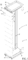
- FIG. 1 illustrates a display apparatus 100 according to an embodiment of the disclosure.
- the display apparatus 100 includes a display panel unit 10 and a support module 20.
- the display panel unit 10 includes a plurality of carrier boxes 11 stacked on each other in a top-bottom direction, and a plurality of display modules 12.
- each display module 12 is an LED display module, but is not limited hereto, and may be an LCD display module, a plasma display module, and so on.
- Each carrier box 11 carries two of the display modules 12.
- the support module 20 includes a housing framework 2, two guide rail units 3, and a carrier 4.
- the housing framework 2 has a front side provided with a front opening 25, a rear side provided with a rear opening 26, and two lateral sides respectively provided with two lateral openings 27.
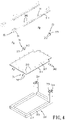
- the housing framework 2 further has two frames 21, two connection rods 22, and a fastening unit 23.
- the frames 21 are respectively disposed at top and bottom sides of the housing framework 2.
- Each frame 21 has a frame body 210, a plate 211, and a plurality of screws 212.
- the frame body 210 has a framing member 213 and two sleeve pipes 214.
- the framing member 213 is of a rectangular hollow shape and has a supporting surface 215 to support the plate 211.
- the sleeve pipes 214 extend upwardly from the supporting surface 215 at a rear side of the housing framework 2, and are spaced apart from each other in a left-right direction.
- Each sleeve pipes 214 has an insertion space 216 for insertion of a corresponding one of the connection rods 22.
- the screws 212 fasten the plate 211 to the supporting surface 215 of the framing member 213.
- the plate 211 has a bearing surface 217 opposite to the supporting surface 215.
- connection rods 22 are respectively disposed at the left and right sides.
- Each connection rod 22 is a rectangular pipe and has inserting ends 221 opposite to each other in the top-bottom direction.
- the inserting ends 221 of each connection rod 22 are respectively inserted into the insertion spaces 216 of the sleeve pipes 214 of the support frames 21 disposed at the top and bottom sides, so that each of the connection rods 22 is connected between rear ends of the support frames 21.
- the fastening unit 23 includes a plurality of first fasteners 231 six of which are shown in Figure 3 and second fasteners 232 three of which are shown in Figure 3 .
- Each first fastener 231 includes a first bolt 233 and a first nut 234.
- the first bolts 233 extend in the left-right direction through the sleeve pipes 214 and the insertion ends 221 of the connection rods 22 and are threaded into the first nuts 234, thereby securing the sleeve pipes 214 and the insertion ends 221 of the connection rods 22.
- Each second fastener 232 has a second bolt 235 and a second nut 236.
- the second bolts 235 extend in the front-rear direction through the sleeve pipes 214 and the insertion ends 221 of the connection rods 22 and are threaded into the second nuts 236, thereby securing the sleeve pipes 214 and the insertion ends 221 of the connection rods 22.
- the connection rods 22 are stably connected to the sleeve pipes 214.
- the front opening 25 is defined between front ends of the frames 21.
- the frames 21 and the connection rods 22 cooperatively define a receiving space 24 in communication with the front opening 25.
- the rear ends of the frames 21 and the connecting rods 22 cooperatively define the rear opening 26 disposed behind and in communication with the receiving space 24.
- Each of the frames 21 has left and right lateral ends each connecting between the front and rear ends of a corresponding one of the frames 21.
- the left lateral ends of the frames 21 and one of the connecting rods 22 cooperatively define one of the lateral openings 27 .
- the right lateral ends of the frames 21 and the other one of the connecting rod 22 cooperatively define the other one of the lateral openings (27) .
- the guide rail units 3 are mounted respectively on the frames 21 at the top and bottom sides of the housing framework 2 and are disposed within the receiving space 24.
- Each of the guide rail units 3 includes two slide rails 30 that are attached to the bearing surface 217 of the plate 211 of one of the frames 21 facing the receiving space 24 and that are spaced apart from each other in a left-right direction.
- Each slide rail 30 includes a linear rail member 31, a sliding block 32, two stop blocks 33, a fixing unit 34, and a track brake 35 (see Figure 5 ) .
- the linear rail member 31 supported by the bearing surface 217 extends in the front-rear direction, and has a front end situated at the front side of the housing framework 2, a rear end situated at the rear side of the housing framework 2, and a slide surface 311 connected between the front and rear ends of the linear rail member 31 away from the bearing surface 217.
- the sliding block 32 has a sliding recess 321 slidably connected to the linear rail member 31.
- the stop blocks 33 are mounted on the bearing surface 217.
- Each stop block 33 has a block body 331, and two lateral protrusions 332 projecting respectively from left and right sides of the block body 331 toward the other one of the stop blocks 33.
- the block bodies 331 of the stop blocks 33 are disposed respectively on front and rear ends of the linear rail member 31.
- the two lateral protrusions 332 of each stop block 33 are respectively disposed on left and right sides of the linear rail member 31.
- the fixing unit 34 includes a plurality of first screws 341 and a plurality of second screws 342.
- the first screws 341 secure the linear rail members 31 of the two slide rails 30 to the plate 211 of the corresponding frame 21.
- the second screws 342 secure the stop blocks 32 to the corresponding plate 211.
- the sliding block 32 has a pivot hole 322 formed in a rear end thereof.
- the track brake 35 is a V-shaped rod and has a connecting arm 351 and a braking arm 352 angled from the connecting arm 351.
- the connecting arm 351 is pivotably inserted into the pivot hole 322 and partially projects outwardly from the pivot hole 322 so as to extend away from the rear end of the sliding block 32.
- the braking arm 352 bends from the connecting arm 351.
- the track brake 35 is rotatable relative to the sliding block 32 between a non-braking position (see Figure 7 ) and a braking position (see Figure 8 ) .
- the braking arm 352 As the track brake 35 is rotated to the non-braking position, the braking arm 352 is moved away from the slide surface 311 of the linear rail member 31, so that the sliding block 32 is slidable on the linear rail member 31. As the track brake 35 is rotated to the braking position, the braking arm 352 is placed in pressing contact with the slide surface 311 of the linear rail member 31 for locking the sliding block 32 against movement.
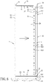
- the carrier 4 is connected between the guide rail units 3 and movable along the guide rail units 3 toward and away from the front opening 25.
- the carrier 4 includes two upright rods 411 spaced apart from each other in the left-right direction, and a plurality of transverse rods 412 connected between the upright rods 411 and spaced apart from each other in the top-bottom direction.
- Each upright rod 411 has a rod body 410 and two end flange plates 413.
- the rod body 410 has an installation surface 414 for installation of the carrier boxes 1 of the display panel unit 10 (see Figure 1 ).
- the end flange plates 413 are respectively welded to top and bottom ends of the rod body 410.
- the end flange plate 413 at the top end of the rod body 410 is connected to the sliding block 32 of one of the slide rails 30 of one of the guide rail units 3 at the top side.
- the end flange plate 413 at the bottom end of the rod body 410 is connected to the slide block 32 of one of the slide rails 30 of the other one of the guide rail units 3 at the bottom side.
- the carrier 4 further includes a plurality of maintenance through holes 415 that are spaced apart from each other in the top-bottom direction and that extend through front to rear carrier surfaces of the carrier 4.
- Each maintenance through hole 415 is defined by two adjacent transverse rods 412 and the upright rods 411.
- the end flange plates 413 are secured to the sliding block 32 by screws 421.
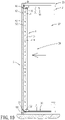
- the carrier 4 is slidable on the slide rails 30 to move backward from the front opening 25 to a rear position (see Figure 6 ), or forward towards the front opening 25 to reach a front position (see Figure 10 ).
- One of the stop blocks 33 is used to abut a front side of the sliding block 32 when the carrier 4 is placed at the front position.
- the other one of the stop blocks 33 is used to abut a rear side of the sliding block 32 when the carrier 4 is placed at the rear position.
- the frame 21 at the bottom side is placed on a platform surface 51, and the front ends of the frames 21 is placed to contact with a back surface 521 of a window glass 52.
- the front opening 25 is adjacent to the back surface 521.
- a user may enter the receiving space 24 through a selected one of the front opening 25, the lateral openings 27 and the rear opening 26 and move the carrier 4 in the front-rear direction.
- the track brake 35 may be rotated along a first rotating direction (R1) to the braking position (see Figure 8 ) so that the carrier 4 is locked at a distance away from the front opening 25.
- the user may enter the receiving space 24 through one of the lateral openings 27 (see Figure 2 ) to stand in front of the carrier 4 for installation of the display panel unit 10.
- rear plates 111 of the carrier boxes 11 are first secured to the installation surfaces 414 of the respective upright rods 411 by using bolts 131 and nuts 132.
- the display modules 12 are assembled to the respective carrier boxes 11. Because the carrier 4 is immobilized at the rear position, stability of the carrier 4 is enhanced during installation of the display panel unit 10 on the carrier 4.
- the track brake 35 is rotated along a second rotating direction (R2) to the non-braking position (see Figure 7 ) to unlock the carrier 4.
- R2 second rotating direction
- the user can enter the receiving space 24 and move the carrier together with the display panel unit 10 to the front opening 25.
- the carrier 4 reaches the front position.
- the carrier 4 is locked at the front position, so that the display modules 12 are closely contiguous to the back surface 521 of the window glass 52. As such, the viewing angle of the display panel unit 10 is increased to display images through the window glass 52.
- the carrier 4 may be moved again toward the rear opening 26 so that the worker may enter the receiving space 24 to stand in front of the display panel unit 10 for maintenance. It is easy to detach, assemble or maintain each display module 12 and each carrier box 11.
- the structural strength of the carrier 4 is enhanced to prevent from deformation thereof, thereby ensuring that the installation surfaces 414 of the upright rods 411 are coplanar and constitute a coplanar surface that extends in top-bottom and left-right directions.
- the carrier 4 is ensured to be stable when sliding in the front-rear direction.
- the display modules 12 are disposed on the same plane.
- the carrier 4 may also be immobilized at a position between the front and rear position for installation or maintenance. Further, it is understandable that the housing framework 2 may have only one lateral opening 27 for entry into the receiving space 24 in other embodiments.
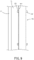
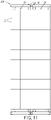
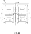
- FIG. 11 and 12 to assemble a plurality of the display panel units 10 for displaying a large size image, multiple support modules 20 are juxtaposed to each other in the left-right direction. To fix the support modules 20 in juxtaposition to each other, the sleeve pipes 214 of the support modules 20 are secured to each other by using bolts 233' and nuts 234'. In addition, to ensure that the display panel units 10 can be simultaneously moved, the carrier boxes 11 juxtaposed to each other are also secured together using bolts (not shown) and nuts (not shown) .
- the display panel unit 10 can be moved forward and placed in a position closely adjacent to the window glass so that the viewing angle of images presented by the display panel unit 10 can be enhanced.
- the display panel unit 10 can also be moved rewardly away from the window glass to facilitate installation, replacement or maintenance of the display panel unit 10.
Landscapes
- Engineering & Computer Science (AREA)
- General Engineering & Computer Science (AREA)
- Physics & Mathematics (AREA)
- General Physics & Mathematics (AREA)
- Theoretical Computer Science (AREA)
- Mechanical Engineering (AREA)
- Microelectronics & Electronic Packaging (AREA)
- Multimedia (AREA)
- Devices For Indicating Variable Information By Combining Individual Elements (AREA)
Applications Claiming Priority (1)
| Application Number | Priority Date | Filing Date | Title |
|---|---|---|---|
| TW110100276A TWI769650B (zh) | 2021-01-05 | 2021-01-05 | 支撐裝置、支撐總成及顯示設備 |
Publications (3)
| Publication Number | Publication Date |
|---|---|
| EP4023923A1 true EP4023923A1 (de) | 2022-07-06 |
| EP4023923B1 EP4023923B1 (de) | 2024-04-24 |
| EP4023923C0 EP4023923C0 (de) | 2024-04-24 |
Family
ID=74874735
Family Applications (1)
| Application Number | Title | Priority Date | Filing Date |
|---|---|---|---|
| EP21162622.1A Active EP4023923B1 (de) | 2021-01-05 | 2021-03-15 | Trägermodul, trägeranordnung und anzeigevorrichtung |
Country Status (3)
| Country | Link |
|---|---|
| US (1) | US11558970B2 (de) |
| EP (1) | EP4023923B1 (de) |
| TW (1) | TWI769650B (de) |
Families Citing this family (3)
| Publication number | Priority date | Publication date | Assignee | Title |
|---|---|---|---|---|
| US11699367B1 (en) * | 2022-02-16 | 2023-07-11 | Ranjit Singh Phagura | Smart display for trailer door or panel |
| KR20240159245A (ko) * | 2023-04-28 | 2024-11-05 | 엘지디스플레이 주식회사 | 표시 장치 |
| CN117218971B (zh) * | 2023-11-08 | 2024-01-30 | 深圳利亚德光电有限公司 | 显示模组及具有其的可前后维护的显示屏 |
Citations (3)
| Publication number | Priority date | Publication date | Assignee | Title |
|---|---|---|---|---|
| CN101546503B (zh) * | 2009-05-06 | 2011-08-17 | 上海优安信息技术有限公司 | 一种可调节液晶拼接显示墙 |
| KR20190001331A (ko) * | 2017-06-27 | 2019-01-04 | 권순성 | 엘이디 광고벽체 지지장치 |
| US10635381B2 (en) * | 2017-05-10 | 2020-04-28 | Mitsubishi Electric Corporation | Multi-display system, video display device, and pull-out mechanism |
Family Cites Families (6)
| Publication number | Priority date | Publication date | Assignee | Title |
|---|---|---|---|---|
| US7002810B1 (en) * | 2003-12-19 | 2006-02-21 | Raytheon Company | System and method for housing electronic equipment in a rack |
| WO2008117463A1 (ja) * | 2007-03-27 | 2008-10-02 | Fujitsu Limited | 電子機器および支持構造体 |
| US7861650B2 (en) * | 2007-04-13 | 2011-01-04 | Illinois Tool Works, Inc. | Method and apparatus for adjusting a substrate support |
| JP5863957B2 (ja) * | 2012-04-27 | 2016-02-17 | 富士機械製造株式会社 | 部品実装機の部品供給ユニットの取付装置 |
| CN105852451B (zh) * | 2016-04-25 | 2018-01-09 | 北京航星机器制造有限公司 | 快递柜及其工作方法 |
| CN112253926A (zh) * | 2020-10-20 | 2021-01-22 | 福建捷联电子有限公司 | 一种led显示屏滑轨安装结构 |
-
2021
- 2021-01-05 TW TW110100276A patent/TWI769650B/zh active
- 2021-03-10 US US17/198,033 patent/US11558970B2/en active Active
- 2021-03-15 EP EP21162622.1A patent/EP4023923B1/de active Active
Patent Citations (3)
| Publication number | Priority date | Publication date | Assignee | Title |
|---|---|---|---|---|
| CN101546503B (zh) * | 2009-05-06 | 2011-08-17 | 上海优安信息技术有限公司 | 一种可调节液晶拼接显示墙 |
| US10635381B2 (en) * | 2017-05-10 | 2020-04-28 | Mitsubishi Electric Corporation | Multi-display system, video display device, and pull-out mechanism |
| KR20190001331A (ko) * | 2017-06-27 | 2019-01-04 | 권순성 | 엘이디 광고벽체 지지장치 |
Also Published As
| Publication number | Publication date |
|---|---|
| US20220217856A1 (en) | 2022-07-07 |
| US11558970B2 (en) | 2023-01-17 |
| TWI769650B (zh) | 2022-07-01 |
| EP4023923B1 (de) | 2024-04-24 |
| TW202228497A (zh) | 2022-07-16 |
| EP4023923C0 (de) | 2024-04-24 |
Similar Documents
| Publication | Publication Date | Title |
|---|---|---|
| EP4023923B1 (de) | Trägermodul, trägeranordnung und anzeigevorrichtung | |
| US8590184B2 (en) | Display device for transportation vehicle | |
| US20110174944A1 (en) | Recess video display mounting system | |
| GB2535842A (en) | Large-scale electronic displays and methods of manufacturing the same | |
| MX2011004760A (es) | Panel de interconexion de fibras terminado en el campo para montaje en soporte y pared. | |
| US20230355010A1 (en) | Display case with mountable panels | |
| US20070194670A1 (en) | Showcase | |
| US20040251043A1 (en) | Modular gangable switch box | |
| CN217035053U (zh) | 一种拼接式led显示系统 | |
| GB2365612A (en) | A display apparatus and cover member | |
| JP3430039B2 (ja) | 電子装置筺体の架台構造 | |
| CN215495869U (zh) | 一种灯箱广告牌 | |
| JPH05130541A (ja) | プロジエクシヨンテレビ | |
| JPH06130495A (ja) | 組合せ形投写形表示装置 | |
| JP4043174B2 (ja) | ショーケースの棚装置 | |
| JP3519626B2 (ja) | 宅配ボックス構造体 | |
| CN214737549U (zh) | 一种交通标志杆用安装装置 | |
| US7787253B1 (en) | Data center rack mount loading system | |
| CN112253926A (zh) | 一种led显示屏滑轨安装结构 | |
| CN214042693U (zh) | 用于模拟座舱的仪表台 | |
| CN219365076U (zh) | 一种铝型材组合式框架结构 | |
| CN216010126U (zh) | 一种用于cob显示屏的简易移动式支架 | |
| CN218954376U (zh) | 一种可拼接串联的安装架 | |
| JP3218059U (ja) | ディスプレイ用引き出しユニット | |
| JP2000157381A (ja) | ショーケースの棚装置 |
Legal Events
| Date | Code | Title | Description |
|---|---|---|---|
| PUAI | Public reference made under article 153(3) epc to a published international application that has entered the european phase |
Free format text: ORIGINAL CODE: 0009012 |
|
| STAA | Information on the status of an ep patent application or granted ep patent |
Free format text: STATUS: THE APPLICATION HAS BEEN PUBLISHED |
|
| AK | Designated contracting states |
Kind code of ref document: A1 Designated state(s): AL AT BE BG CH CY CZ DE DK EE ES FI FR GB GR HR HU IE IS IT LI LT LU LV MC MK MT NL NO PL PT RO RS SE SI SK SM TR |
|
| STAA | Information on the status of an ep patent application or granted ep patent |
Free format text: STATUS: REQUEST FOR EXAMINATION WAS MADE |
|
| 17P | Request for examination filed |
Effective date: 20230105 |
|
| RBV | Designated contracting states (corrected) |
Designated state(s): AL AT BE BG CH CY CZ DE DK EE ES FI FR GB GR HR HU IE IS IT LI LT LU LV MC MK MT NL NO PL PT RO RS SE SI SK SM TR |
|
| GRAP | Despatch of communication of intention to grant a patent |
Free format text: ORIGINAL CODE: EPIDOSNIGR1 |
|
| STAA | Information on the status of an ep patent application or granted ep patent |
Free format text: STATUS: GRANT OF PATENT IS INTENDED |
|
| INTG | Intention to grant announced |
Effective date: 20231114 |
|
| GRAS | Grant fee paid |
Free format text: ORIGINAL CODE: EPIDOSNIGR3 |
|
| GRAA | (expected) grant |
Free format text: ORIGINAL CODE: 0009210 |
|
| STAA | Information on the status of an ep patent application or granted ep patent |
Free format text: STATUS: THE PATENT HAS BEEN GRANTED |
|
| AK | Designated contracting states |
Kind code of ref document: B1 Designated state(s): AL AT BE BG CH CY CZ DE DK EE ES FI FR GB GR HR HU IE IS IT LI LT LU LV MC MK MT NL NO PL PT RO RS SE SI SK SM TR |
|
| REG | Reference to a national code |
Ref country code: GB Ref legal event code: FG4D |
|
| REG | Reference to a national code |
Ref country code: CH Ref legal event code: EP |
|
| REG | Reference to a national code |
Ref country code: DE Ref legal event code: R096 Ref document number: 602021012111 Country of ref document: DE |
|
| REG | Reference to a national code |
Ref country code: IE Ref legal event code: FG4D |
|
| U01 | Request for unitary effect filed |
Effective date: 20240425 |
|
| U07 | Unitary effect registered |
Designated state(s): AT BE BG DE DK EE FI FR IT LT LU LV MT NL PT SE SI Effective date: 20240506 |
|
| PG25 | Lapsed in a contracting state [announced via postgrant information from national office to epo] |
Ref country code: IS Free format text: LAPSE BECAUSE OF FAILURE TO SUBMIT A TRANSLATION OF THE DESCRIPTION OR TO PAY THE FEE WITHIN THE PRESCRIBED TIME-LIMIT Effective date: 20240824 |
|
| PG25 | Lapsed in a contracting state [announced via postgrant information from national office to epo] |
Ref country code: HR Free format text: LAPSE BECAUSE OF FAILURE TO SUBMIT A TRANSLATION OF THE DESCRIPTION OR TO PAY THE FEE WITHIN THE PRESCRIBED TIME-LIMIT Effective date: 20240424 |
|
| PG25 | Lapsed in a contracting state [announced via postgrant information from national office to epo] |
Ref country code: GR Free format text: LAPSE BECAUSE OF FAILURE TO SUBMIT A TRANSLATION OF THE DESCRIPTION OR TO PAY THE FEE WITHIN THE PRESCRIBED TIME-LIMIT Effective date: 20240725 |
|
| PG25 | Lapsed in a contracting state [announced via postgrant information from national office to epo] |
Ref country code: ES Free format text: LAPSE BECAUSE OF FAILURE TO SUBMIT A TRANSLATION OF THE DESCRIPTION OR TO PAY THE FEE WITHIN THE PRESCRIBED TIME-LIMIT Effective date: 20240424 |
|
| PG25 | Lapsed in a contracting state [announced via postgrant information from national office to epo] |
Ref country code: PL Free format text: LAPSE BECAUSE OF FAILURE TO SUBMIT A TRANSLATION OF THE DESCRIPTION OR TO PAY THE FEE WITHIN THE PRESCRIBED TIME-LIMIT Effective date: 20240424 |
|
| PG25 | Lapsed in a contracting state [announced via postgrant information from national office to epo] |
Ref country code: PL Free format text: LAPSE BECAUSE OF FAILURE TO SUBMIT A TRANSLATION OF THE DESCRIPTION OR TO PAY THE FEE WITHIN THE PRESCRIBED TIME-LIMIT Effective date: 20240424 Ref country code: NO Free format text: LAPSE BECAUSE OF FAILURE TO SUBMIT A TRANSLATION OF THE DESCRIPTION OR TO PAY THE FEE WITHIN THE PRESCRIBED TIME-LIMIT Effective date: 20240724 Ref country code: IS Free format text: LAPSE BECAUSE OF FAILURE TO SUBMIT A TRANSLATION OF THE DESCRIPTION OR TO PAY THE FEE WITHIN THE PRESCRIBED TIME-LIMIT Effective date: 20240824 Ref country code: HR Free format text: LAPSE BECAUSE OF FAILURE TO SUBMIT A TRANSLATION OF THE DESCRIPTION OR TO PAY THE FEE WITHIN THE PRESCRIBED TIME-LIMIT Effective date: 20240424 Ref country code: GR Free format text: LAPSE BECAUSE OF FAILURE TO SUBMIT A TRANSLATION OF THE DESCRIPTION OR TO PAY THE FEE WITHIN THE PRESCRIBED TIME-LIMIT Effective date: 20240725 Ref country code: ES Free format text: LAPSE BECAUSE OF FAILURE TO SUBMIT A TRANSLATION OF THE DESCRIPTION OR TO PAY THE FEE WITHIN THE PRESCRIBED TIME-LIMIT Effective date: 20240424 Ref country code: RS Free format text: LAPSE BECAUSE OF FAILURE TO SUBMIT A TRANSLATION OF THE DESCRIPTION OR TO PAY THE FEE WITHIN THE PRESCRIBED TIME-LIMIT Effective date: 20240724 |
|
| PG25 | Lapsed in a contracting state [announced via postgrant information from national office to epo] |
Ref country code: CZ Free format text: LAPSE BECAUSE OF FAILURE TO SUBMIT A TRANSLATION OF THE DESCRIPTION OR TO PAY THE FEE WITHIN THE PRESCRIBED TIME-LIMIT Effective date: 20240424 |
|
| PG25 | Lapsed in a contracting state [announced via postgrant information from national office to epo] |
Ref country code: SK Free format text: LAPSE BECAUSE OF FAILURE TO SUBMIT A TRANSLATION OF THE DESCRIPTION OR TO PAY THE FEE WITHIN THE PRESCRIBED TIME-LIMIT Effective date: 20240424 Ref country code: RO Free format text: LAPSE BECAUSE OF FAILURE TO SUBMIT A TRANSLATION OF THE DESCRIPTION OR TO PAY THE FEE WITHIN THE PRESCRIBED TIME-LIMIT Effective date: 20240424 |
|
| REG | Reference to a national code |
Ref country code: DE Ref legal event code: R097 Ref document number: 602021012111 Country of ref document: DE |
|
| PG25 | Lapsed in a contracting state [announced via postgrant information from national office to epo] |
Ref country code: SM Free format text: LAPSE BECAUSE OF FAILURE TO SUBMIT A TRANSLATION OF THE DESCRIPTION OR TO PAY THE FEE WITHIN THE PRESCRIBED TIME-LIMIT Effective date: 20240424 |
|
| PG25 | Lapsed in a contracting state [announced via postgrant information from national office to epo] |
Ref country code: SM Free format text: LAPSE BECAUSE OF FAILURE TO SUBMIT A TRANSLATION OF THE DESCRIPTION OR TO PAY THE FEE WITHIN THE PRESCRIBED TIME-LIMIT Effective date: 20240424 Ref country code: SK Free format text: LAPSE BECAUSE OF FAILURE TO SUBMIT A TRANSLATION OF THE DESCRIPTION OR TO PAY THE FEE WITHIN THE PRESCRIBED TIME-LIMIT Effective date: 20240424 Ref country code: RO Free format text: LAPSE BECAUSE OF FAILURE TO SUBMIT A TRANSLATION OF THE DESCRIPTION OR TO PAY THE FEE WITHIN THE PRESCRIBED TIME-LIMIT Effective date: 20240424 Ref country code: CZ Free format text: LAPSE BECAUSE OF FAILURE TO SUBMIT A TRANSLATION OF THE DESCRIPTION OR TO PAY THE FEE WITHIN THE PRESCRIBED TIME-LIMIT Effective date: 20240424 |
|
| U20 | Renewal fee for the european patent with unitary effect paid |
Year of fee payment: 5 Effective date: 20250113 |
|
| PLBE | No opposition filed within time limit |
Free format text: ORIGINAL CODE: 0009261 |
|
| STAA | Information on the status of an ep patent application or granted ep patent |
Free format text: STATUS: NO OPPOSITION FILED WITHIN TIME LIMIT |
|
| 26N | No opposition filed |
Effective date: 20250127 |
|
| PG25 | Lapsed in a contracting state [announced via postgrant information from national office to epo] |
Ref country code: MC Free format text: LAPSE BECAUSE OF FAILURE TO SUBMIT A TRANSLATION OF THE DESCRIPTION OR TO PAY THE FEE WITHIN THE PRESCRIBED TIME-LIMIT Effective date: 20240424 |
|
| REG | Reference to a national code |
Ref country code: CH Ref legal event code: H13 Free format text: ST27 STATUS EVENT CODE: U-0-0-H10-H13 (AS PROVIDED BY THE NATIONAL OFFICE) Effective date: 20251023 |
|
| GBPC | Gb: european patent ceased through non-payment of renewal fee |
Effective date: 20250315 |