EP4023829B1 - Quelldichtung für eine feuerbeständige fassadenkonstruktion und damit ausgestattete fassadenkonstruktion - Google Patents
Quelldichtung für eine feuerbeständige fassadenkonstruktion und damit ausgestattete fassadenkonstruktion Download PDFInfo
- Publication number
- EP4023829B1 EP4023829B1 EP21218483.2A EP21218483A EP4023829B1 EP 4023829 B1 EP4023829 B1 EP 4023829B1 EP 21218483 A EP21218483 A EP 21218483A EP 4023829 B1 EP4023829 B1 EP 4023829B1
- Authority
- EP
- European Patent Office
- Prior art keywords
- swelling
- strips
- facade construction
- construction according
- profiles
- Prior art date
- Legal status (The legal status is an assumption and is not a legal conclusion. Google has not performed a legal analysis and makes no representation as to the accuracy of the status listed.)
- Active
Links
Images


Classifications
-
- E—FIXED CONSTRUCTIONS
- E04—BUILDING
- E04B—GENERAL BUILDING CONSTRUCTIONS; WALLS, e.g. PARTITIONS; ROOFS; FLOORS; CEILINGS; INSULATION OR OTHER PROTECTION OF BUILDINGS
- E04B2/00—Walls, e.g. partitions, for buildings; Wall construction with regard to insulation; Connections specially adapted to walls
- E04B2/88—Curtain walls
- E04B2/96—Curtain walls comprising panels attached to the structure through mullions or transoms
- E04B2/967—Details of the cross-section of the mullions or transoms
-
- E—FIXED CONSTRUCTIONS
- E04—BUILDING
- E04B—GENERAL BUILDING CONSTRUCTIONS; WALLS, e.g. PARTITIONS; ROOFS; FLOORS; CEILINGS; INSULATION OR OTHER PROTECTION OF BUILDINGS
- E04B1/00—Constructions in general; Structures which are not restricted either to walls, e.g. partitions, or floors or ceilings or roofs
- E04B1/62—Insulation or other protection; Elements or use of specified material therefor
- E04B1/92—Protection against other undesired influences or dangers
- E04B1/94—Protection against other undesired influences or dangers against fire
-
- E—FIXED CONSTRUCTIONS
- E04—BUILDING
- E04B—GENERAL BUILDING CONSTRUCTIONS; WALLS, e.g. PARTITIONS; ROOFS; FLOORS; CEILINGS; INSULATION OR OTHER PROTECTION OF BUILDINGS
- E04B1/00—Constructions in general; Structures which are not restricted either to walls, e.g. partitions, or floors or ceilings or roofs
- E04B1/62—Insulation or other protection; Elements or use of specified material therefor
- E04B1/66—Sealings
- E04B1/68—Sealings of joints, e.g. expansion joints
- E04B2001/6818—Joints with swellable parts
Definitions
- the present invention relates to a fire-resistant facade construction equipped with a swelling seal.
- the invention relates to a facade construction of the curtain wall type.
- curtain walls are known and built around a skeleton of profiles made from aluminium or the like in the form of mullions and transoms which form adjoining frames for façade panels, typically glass panels.
- the panels are clamped along the edges against the aforementioned front sides of the mullions and transoms by means of screws which are screwed in the aforementioned screw channels through an insulation profile made from thermal insulation material which has been pushed into the screw channel in advance with an insert edge.
- Said swelling seals are made of a material which in the event of a fire will swell up under the influence of the heat, with the intention of filling the space around the panels thereby preventing hot air from flowing to the non-burning side such that the flames are at least temporarily prevented from flashing over and no oxygen is supplied to the burning side which could fan the fire.
- said swelling seals are glued separately on the aluminium profiles when building the facade construction, typically on either side of the ribs defining the screw channel.
- Another disadvantage is that when applying the swelling seals at low temperatures and damp weather a bad adhesion of the glue is obtained and glueing in adverse weather conditions is thus not recommended.
- the spacer of the swelling seal contains a U-shaped profiled section with legs which run essentially parallel with the swelling strips, whereby the form and the dimensions of said U-shaped section are preferably such that upon mounting the swelling seal it fittingly slides in the screw channel.
- the swelling seal is first slid over said insert edge of the insulation profile with the U-shaped section, after which the assembly can be slid as a whole into the screw channel of the facade profile, such that the swelling seal is affixed.
- a facade construction according to the invention containing a skeleton of profiles made from aluminium or the like in the form of mullions and transoms of adjoining frames for facade panels and which on their front sides facing the outside of the façade construction are provided with an open screw channel delimited by two parallel protruding ribs of the profiles which define a rebate in which the panels are attached with a certain lateral play by means of clamping profiles which cover the edges of the panels and which are clamped against said front sides of the mullions and transoms by means of screws which are screwed in said screw channels, wherein the facade construction is provided with swelling seals containing two swelling strips made of a material which in the event of a fire swell up under the influence of heat, the swelling strips being interconnected by at least one spacer which holds the swelling strips at a distance from each other and containing a U-shaped profiled section with legs that run parallel with the swelling strips, whereby the swelling seals are fittingly slid over the ribs of the screw channels of
- Said type of swelling seal makes it easy to also use insulating parts (Hi-foam) in combination with a swelling seal.
- the swelling seal according to the invention is slid over the ribs of the screw channel with the swelling strips on either sides of the ribs of the screw channel.
- the swelling seal is kept in place by the insulation profile and the screws in the screw channel.
- the advantage is that the swelling seal does not necessarily have to be glued.
- the strips can be applied in all weather conditions, even in cold and damp weather.
- the swelling seal is made as an extruded profile or a co-extruded profile if the spacer is made from another material than that of the swelling strips, for example from synthetic material.
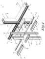
- Figure 1 shows the skeleton of a facade construction 1 according to the invention which is constructed from mullions 2 and transoms 3 in the form of profiles made from aluminium or the like.
- the front sides of the profiles 2 and 3 facing the outside 4 of the facade construction 5 are provided with an open screw channel 6 that is delimited by two parallel protruding ribs 7 of the profiles 2 and 3 which define a rebate 8 in which, as shown in figure 4 , glass or other panels 9 are attached with a certain play S by means of clamping profiles 10 which clamp the edges of the panels 9 between seals 11 on the front side 5 of the profiles and the underside of the clamping profiles 10.
- the clamping profiles 10 are screwed against the panels 9 by means of screws 12 which are screwed in the screw channels 6 through insulation profiles 13 made from insulation foam or the like which are enclosed in the screw channels 6 in the known way with a longitudinal insert edge 14.
- the clamping profiles 10 and screws 12 are covered by means of finishing profiles 15 which are snapped onto the clamping profiles 10.
- the facade construction 1 is made with swelling seals 16 according to the invention which are made with two parallel tape-shaped swelling strips 17 made from a material which in the event of a fire swell up under the influence of heat.
- swelling strips 17 are interconnected by at least one spacer 18 made from synthetic material or the like which interconnects the swelling strips 17 and holds them at a distance A from each other which is essentially equal to the breadth B measured between the outsides of the two ribs 7.
- the spacer 18 contains a U-shaped profiled section 19 with legs 20 which run essentially parallel with the swelling strips 17 at a distance from the swelling strips 17 equal to the breadth B' of the ribs 7 and which at their free end are each connected with a swelling strip 17 by means of a cross member 21 at a distance from both longitudinal edges 22 of the swelling strips 17, respectively at a distance C and D.
- the form and dimensions of the swelling seals 16 are such that the swelling seals 16 can be fittingly slid over the ribs 7 with the U-shaped section 19 in the screw channels 6 with the opening to the outside 4 of the facade construction 1 and the swelling strips 17 fittingly over the outside of the ribs 7 and over the entire or practically entire length E of the ribs 7.
- the swelling seal 16 is thereby first slid with the U-shaped section 19 over said insert edge 14 of the insulation profile 13 for example, after which the assembly can be slid as a whole into a screw channel 6 of the profiles 2 and 3, such that the swelling seal is affixed as shown in the figures 2 and 3 .
- the spacer 18 may be made from another material than the swelling strips 17, in which case the swelling seals 16 may, for example, be co-extruded.
- the entire swelling seal 16 is made from the same material by extrusion or the like.
- the swelling strips are glued or co-extruded on a slat-shaped support made from synthetic material or the like which analogously as above are interconnected by a spacer.
- the support and spacer can also be obtained by injection moulding, for example, and the spacer can also be interrupted lengthways of the swelling seal.
- the insulation profiles 13 show a beam-shaped body 23, the breadth of which is approximately equal to the breadth on the outside of the ribs 7 of the screw channels 6 and which over a certain length fits on the side of the insert edge 14 between the swelling strips 17.
- the swelling strips 17 overlap the body 23 over a said distance D and the body 23 protrudes with a section with length F from the swelling seal 16, whereby said section is or can be surrounded by insulating parts 24 with laterally projecting wings 25 from high-grade thermal insulation foam.
- figures 5 and 6 show the situation for the mullions 2 with a swelling seal 16 and insulation profile 13 with essentially the same properties as aforementioned but a slightly deviating form and dimensions.
Landscapes
- Engineering & Computer Science (AREA)
- Architecture (AREA)
- Physics & Mathematics (AREA)
- Electromagnetism (AREA)
- Civil Engineering (AREA)
- Structural Engineering (AREA)
- Load-Bearing And Curtain Walls (AREA)
- Building Environments (AREA)
Claims (11)
- Fassadenstruktur, die ein Skelett aus Profilen enthält, die aus Aluminium oder ähnlichem in der Form von Pfosten (2) und Querbalken (3) von angrenzenden Rahmen für Fassadenpaneele (9) ausgeführt sind und die an ihren vorderen Seiten (5), die in Richtung der Außenseite der Fassadenstruktur (1) ausgerichtet sind, mit einem offenen Schraubenkanal (6) versehen sind, der durch zwei hervorstehende parallele Rippen (7) der Profile begrenzt wird, die einen Falz (8) definieren, in dem die Paneele (9) mit einem gewissen seitlichen Spiel mittels Klemmprofile (10) befestigt sind, die die Kanten der Paneele (9) überbedecken und die an den oben genannten vorderen Seiten (5) der Pfosten (2) und der Querbalken (3) mittels Schrauben (12) befestigt sind, die in die oben genannten Schraubenkanäle (6) eingeschraubt sind; wobei die Fassadenstruktur (1) mit aufquellenden Dichtungen (16) ausgestattet ist, die zwei aufquellende Streifen (17) enthalten, die aus einem Material ausgeführt sind, das sich im Brandfall unter Hitzeeinwirkung ausdehnt; wobei die aufquellenden Streifen (17) mittels eines Abstandshalters (18) miteinander verbunden sind, die die aufquellenden Streifen (17) in einem Abstand (A) voneinander hält; wobei die aufquellenden Dichtungen (16) mit ihren aufquellenden Streifen (17) auf beiden Seiten der Schraubenkanäle (6) gleitend über die Rippen (7) der Schraubenkanäle (6) der Pfosten (2) und der Querbalken (3) angebracht werden; dadurch gekennzeichnet, dass der Abstandshalter (18) einen U-förmig ausgebildeten Profilteil (19) besitzt, der Schenkel (20) umfasst, die sich parallel zu den aufquellenden Streifen (17) erstrecken; und dass die aufquellenden Dichtungen (16) gleitend mit ihrem U-förmig ausgebildeten Teil (19) in die Schraubenkanäle (6) passen; wobei die Öffnung des U-förmig ausgebildeten Teils (19) in Richtung der Außenseite (4) der Fassadenstruktur (1) ausgerichtet ist.
- Fassadenstruktur nach Anspruch 1, dadurch gekennzeichnet, dass die aufquellende Dichtung (16) in der Form eines extrudierten oder eines coextrudierten Profils ausgeführt ist.
- Fassadenstruktur nach Anspruch 1 oder 2, dadurch gekennzeichnet, dass die aufquellenden Streifen (17) sich im Wesentlichen parallel zueinander erstrecken.
- Fassadenstruktur nach einem der vorstehenden Ansprüche, dadurch gekennzeichnet, dass die Schenkel (20) des U-förmig ausgebildeten Profilteils (19) in einem Abstand (B') von den aufquellenden Streifen (17) angebracht sind, der gleich der Breite (B) der Rippen (7) ist.
- Fassadenstruktur nach Anspruch 4, dadurch gekennzeichnet, dass die Schenkel des U-förmig ausgebildeten Profilteils (19) mit ihren freien Enden mittels eines kreuzförmigen Elements (21) des Abstandshalters (18) mit den aufquellenden Streifen (17) verbunden sind.
- Fassadenstruktur nach Anspruch 5, dadurch gekennzeichnet, dass die kreuzförmigen Elemente (21) mit den aufquellenden Streifen (17) in einem Abstand (C, D) von den Längskanten (22) der aufquellenden Streifen (17) verbunden sind.
- Fassadenstruktur nach einem der vorstehenden Ansprüche, dadurch gekennzeichnet, dass zwischen den Schraubenkanälen (6) und den Klemmprofilen (10) ein Isolierprofil (13) vorgesehen ist, das aus einem wärmeisolierenden Schaumstoff oder einem anderen Isoliermaterial ausgeführt ist und mit einer Einsatzkante (14) in den U-förmig ausgebildeten Teil (19) der aufquellende Dichtung (16) bis in den Schneckenkanal (6) hinein gleitend passend angebracht wird.
- Fassadenstruktur nach Anspruch 7, dadurch gekennzeichnet, dass die oben genannten Schrauben (12) durch die Isolationsprofile (13) in Schraubenkanäle (6) eingeschraubt sind.
- Fassadenstruktur nach Anspruch 7 oder 8, dadurch gekennzeichnet, dass die Isolierprofile (13) relativ zur Einsatzkante (14) einen breiteren Körper (23) aufweisen, dessen Breite etwa gleich der Breite (B), an der Außenseite der Rippen (7), der Schraubenkanäle (6) ist.
- Fassadenstruktur nach Anspruch 9, dadurch gekennzeichnet, dass die aufquellende Dichtung (16) mit den aufquellenden Streifen (17) sich über eine bestimmte Länge (D) des oben genannten Körpers (23) des Isolierprofils (13) erstreckt.
- Fassadenstruktur nach Anspruch 9 oder 10, dadurch gekennzeichnet, dass der Körper (23) sich über eine bestimmte Länge (F) in Bezug auf die aufquellende Dichtung (16) nach außen erstreckt; wobei der oben genannte Teil von Isolationselementen (24) umgeben ist, die einen oder mehrere in seitlicher Richtung vorstehende Flügel (25) umfassen, die aus einem Material ausgeführt sind, das eine Wärmeisolierung bereitstellt.
Applications Claiming Priority (1)
| Application Number | Priority Date | Filing Date | Title |
|---|---|---|---|
| BE20215003A BE1028989B1 (nl) | 2021-01-05 | 2021-01-05 | Zweldichting voor een brandwerende gevelconstructie en gevelconstructie daarmee uitgerust |
Publications (3)
| Publication Number | Publication Date |
|---|---|
| EP4023829A1 EP4023829A1 (de) | 2022-07-06 |
| EP4023829B1 true EP4023829B1 (de) | 2025-04-30 |
| EP4023829C0 EP4023829C0 (de) | 2025-04-30 |
Family
ID=74186378
Family Applications (1)
| Application Number | Title | Priority Date | Filing Date |
|---|---|---|---|
| EP21218483.2A Active EP4023829B1 (de) | 2021-01-05 | 2021-12-31 | Quelldichtung für eine feuerbeständige fassadenkonstruktion und damit ausgestattete fassadenkonstruktion |
Country Status (3)
| Country | Link |
|---|---|
| EP (1) | EP4023829B1 (de) |
| BE (1) | BE1028989B1 (de) |
| PL (1) | PL4023829T3 (de) |
Families Citing this family (1)
| Publication number | Priority date | Publication date | Assignee | Title |
|---|---|---|---|---|
| DE102022117885A1 (de) * | 2022-07-18 | 2024-01-18 | HUECK System GmbH & Co. KG | Fassade oder lichtdach mit einem riegel- oder pfostenprofil |
Family Cites Families (4)
| Publication number | Priority date | Publication date | Assignee | Title |
|---|---|---|---|---|
| DE202006004165U1 (de) * | 2006-03-16 | 2007-04-19 | Henkenjohann, Johann | Isolator für eine aus Profilen bestehende Pfosten/Riegel-Fassadenkonstruktion |
| DE102007053659A1 (de) * | 2007-11-08 | 2009-05-20 | Hermann Gutmann Werke Ag | Gebäudefassade in Brandschutzausführung |
| DE102014108264A1 (de) * | 2014-06-12 | 2015-12-17 | Ensinger Gmbh | Wärmeisolierendes Abstandhalterprofil |
| EP3034709A1 (de) * | 2014-12-17 | 2016-06-22 | HILTI Aktiengesellschaft | Fassadenbaugruppe, Gebäudeaufbau und Verfahren zur Montage der Fassadenbaugruppe |
-
2021
- 2021-01-05 BE BE20215003A patent/BE1028989B1/nl active IP Right Grant
- 2021-12-31 EP EP21218483.2A patent/EP4023829B1/de active Active
- 2021-12-31 PL PL21218483.2T patent/PL4023829T3/pl unknown
Also Published As
| Publication number | Publication date |
|---|---|
| BE1028989B1 (nl) | 2022-08-10 |
| PL4023829T3 (pl) | 2025-09-08 |
| BE1028989A1 (nl) | 2022-08-01 |
| EP4023829A1 (de) | 2022-07-06 |
| EP4023829C0 (de) | 2025-04-30 |
Similar Documents
| Publication | Publication Date | Title |
|---|---|---|
| EP2318634B1 (de) | Dichtungsmembran zur abdichtung von lücken zwischen rahmen eines fensters und rauen öffnungen | |
| US9359806B2 (en) | Combination marine and stop frame glazed panel and method for the same | |
| US8997412B1 (en) | Combination marine and stop frame glazed panel | |
| US4799332A (en) | Sliding window | |
| KR102727587B1 (ko) | 파사드, 파사드 요소, 윈도우 또는 도어를 위한 프레임 | |
| EA013047B1 (ru) | Строительный элемент | |
| EP0793760B1 (de) | Verglasungstafel | |
| EP4023829B1 (de) | Quelldichtung für eine feuerbeständige fassadenkonstruktion und damit ausgestattete fassadenkonstruktion | |
| ES2963337T3 (es) | Montantes, travesaños y sistemas de ventanas y muros cortina | |
| US10648226B2 (en) | Main-frame bar and/or wing-frame bar, and door, window, or façade element | |
| WO1997018365A1 (en) | Panel sealing structure | |
| GB2142357A (en) | Curtain wall assembly | |
| HUP9904612A2 (hu) | Hőszigetelő távtartó szigetelt üvegezéshez | |
| EP0797711B1 (de) | System von profilen | |
| US6185882B1 (en) | Bullet resistant window assembly | |
| EP4048849B1 (de) | Feuerfeste plattenkonstruktion für gebäude und dafür verwendete feuerfeste glasklammer | |
| GB2157336A (en) | Partitions | |
| HU176449B (en) | Hollow profile frame particularly for doors,windows and similar opening closing devices | |
| US4471597A (en) | Extruded plastic window framing | |
| RU2658814C1 (ru) | Система утепления стоечно-ригельного остекления балконов и способ ее установки | |
| RU202526U1 (ru) | Профиль для фасадных и оконных конструкций | |
| GB2239466A (en) | Curtain wall | |
| GB2110284A (en) | Frame member for doors and windows | |
| WO1990004689A1 (en) | System for mounting glazing or other infill panels in cladding for buildings | |
| IT201900003263A1 (it) | Finestra |
Legal Events
| Date | Code | Title | Description |
|---|---|---|---|
| PUAI | Public reference made under article 153(3) epc to a published international application that has entered the european phase |
Free format text: ORIGINAL CODE: 0009012 |
|
| STAA | Information on the status of an ep patent application or granted ep patent |
Free format text: STATUS: THE APPLICATION HAS BEEN PUBLISHED |
|
| AK | Designated contracting states |
Kind code of ref document: A1 Designated state(s): AL AT BE BG CH CY CZ DE DK EE ES FI FR GB GR HR HU IE IS IT LI LT LU LV MC MK MT NL NO PL PT RO RS SE SI SK SM TR |
|
| STAA | Information on the status of an ep patent application or granted ep patent |
Free format text: STATUS: REQUEST FOR EXAMINATION WAS MADE |
|
| 17P | Request for examination filed |
Effective date: 20221004 |
|
| RBV | Designated contracting states (corrected) |
Designated state(s): AL AT BE BG CH CY CZ DE DK EE ES FI FR GB GR HR HU IE IS IT LI LT LU LV MC MK MT NL NO PL PT RO RS SE SI SK SM TR |
|
| GRAP | Despatch of communication of intention to grant a patent |
Free format text: ORIGINAL CODE: EPIDOSNIGR1 |
|
| STAA | Information on the status of an ep patent application or granted ep patent |
Free format text: STATUS: GRANT OF PATENT IS INTENDED |
|
| RIC1 | Information provided on ipc code assigned before grant |
Ipc: E04B 1/94 20060101ALN20250115BHEP Ipc: E04B 1/68 20060101ALN20250115BHEP Ipc: E04B 2/96 20060101AFI20250115BHEP |
|
| INTG | Intention to grant announced |
Effective date: 20250131 |
|
| GRAS | Grant fee paid |
Free format text: ORIGINAL CODE: EPIDOSNIGR3 |
|
| GRAA | (expected) grant |
Free format text: ORIGINAL CODE: 0009210 |
|
| STAA | Information on the status of an ep patent application or granted ep patent |
Free format text: STATUS: THE PATENT HAS BEEN GRANTED |
|
| AK | Designated contracting states |
Kind code of ref document: B1 Designated state(s): AL AT BE BG CH CY CZ DE DK EE ES FI FR GB GR HR HU IE IS IT LI LT LU LV MC MK MT NL NO PL PT RO RS SE SI SK SM TR |
|
| REG | Reference to a national code |
Ref country code: CH Ref legal event code: EP Ref country code: GB Ref legal event code: FG4D |
|
| REG | Reference to a national code |
Ref country code: IE Ref legal event code: FG4D |
|
| U01 | Request for unitary effect filed |
Effective date: 20250506 |
|
| U07 | Unitary effect registered |
Designated state(s): AT BE BG DE DK EE FI FR IT LT LU LV MT NL PT RO SE SI Effective date: 20250512 |
|
| PG25 | Lapsed in a contracting state [announced via postgrant information from national office to epo] |
Ref country code: ES Free format text: LAPSE BECAUSE OF FAILURE TO SUBMIT A TRANSLATION OF THE DESCRIPTION OR TO PAY THE FEE WITHIN THE PRESCRIBED TIME-LIMIT Effective date: 20250430 |
|
| PG25 | Lapsed in a contracting state [announced via postgrant information from national office to epo] |
Ref country code: NO Free format text: LAPSE BECAUSE OF FAILURE TO SUBMIT A TRANSLATION OF THE DESCRIPTION OR TO PAY THE FEE WITHIN THE PRESCRIBED TIME-LIMIT Effective date: 20250730 Ref country code: GR Free format text: LAPSE BECAUSE OF FAILURE TO SUBMIT A TRANSLATION OF THE DESCRIPTION OR TO PAY THE FEE WITHIN THE PRESCRIBED TIME-LIMIT Effective date: 20250731 |
|
| PG25 | Lapsed in a contracting state [announced via postgrant information from national office to epo] |
Ref country code: HR Free format text: LAPSE BECAUSE OF FAILURE TO SUBMIT A TRANSLATION OF THE DESCRIPTION OR TO PAY THE FEE WITHIN THE PRESCRIBED TIME-LIMIT Effective date: 20250430 |
|
| PG25 | Lapsed in a contracting state [announced via postgrant information from national office to epo] |
Ref country code: RS Free format text: LAPSE BECAUSE OF FAILURE TO SUBMIT A TRANSLATION OF THE DESCRIPTION OR TO PAY THE FEE WITHIN THE PRESCRIBED TIME-LIMIT Effective date: 20250731 |
|
| PG25 | Lapsed in a contracting state [announced via postgrant information from national office to epo] |
Ref country code: IS Free format text: LAPSE BECAUSE OF FAILURE TO SUBMIT A TRANSLATION OF THE DESCRIPTION OR TO PAY THE FEE WITHIN THE PRESCRIBED TIME-LIMIT Effective date: 20250830 |
|
| REG | Reference to a national code |
Ref country code: CH Ref legal event code: U11 Free format text: ST27 STATUS EVENT CODE: U-0-0-U10-U11 (AS PROVIDED BY THE NATIONAL OFFICE) Effective date: 20260101 |
|
| PGFP | Annual fee paid to national office [announced via postgrant information from national office to epo] |
Ref country code: GB Payment date: 20251218 Year of fee payment: 5 |
|
| PG25 | Lapsed in a contracting state [announced via postgrant information from national office to epo] |
Ref country code: SM Free format text: LAPSE BECAUSE OF FAILURE TO SUBMIT A TRANSLATION OF THE DESCRIPTION OR TO PAY THE FEE WITHIN THE PRESCRIBED TIME-LIMIT Effective date: 20250430 |
|
| PG25 | Lapsed in a contracting state [announced via postgrant information from national office to epo] |
Ref country code: CZ Free format text: LAPSE BECAUSE OF FAILURE TO SUBMIT A TRANSLATION OF THE DESCRIPTION OR TO PAY THE FEE WITHIN THE PRESCRIBED TIME-LIMIT Effective date: 20250430 |
|
| PGFP | Annual fee paid to national office [announced via postgrant information from national office to epo] |
Ref country code: IE Payment date: 20251218 Year of fee payment: 5 |
|
| PGFP | Annual fee paid to national office [announced via postgrant information from national office to epo] |
Ref country code: PL Payment date: 20251219 Year of fee payment: 5 |
|
| PG25 | Lapsed in a contracting state [announced via postgrant information from national office to epo] |
Ref country code: SK Free format text: LAPSE BECAUSE OF FAILURE TO SUBMIT A TRANSLATION OF THE DESCRIPTION OR TO PAY THE FEE WITHIN THE PRESCRIBED TIME-LIMIT Effective date: 20250430 |
|
| U20 | Renewal fee for the european patent with unitary effect paid |
Year of fee payment: 5 Effective date: 20251222 |