EP4023312B1 - Spielfahrzeug - Google Patents
Spielfahrzeug Download PDFInfo
- Publication number
- EP4023312B1 EP4023312B1 EP21212281.6A EP21212281A EP4023312B1 EP 4023312 B1 EP4023312 B1 EP 4023312B1 EP 21212281 A EP21212281 A EP 21212281A EP 4023312 B1 EP4023312 B1 EP 4023312B1
- Authority
- EP
- European Patent Office
- Prior art keywords
- swivel
- locking
- locking body
- tilting
- tilt
- Prior art date
- Legal status (The legal status is an assumption and is not a legal conclusion. Google has not performed a legal analysis and makes no representation as to the accuracy of the status listed.)
- Active
Links
Images








Classifications
-
- A—HUMAN NECESSITIES
- A63—SPORTS; GAMES; AMUSEMENTS
- A63H—TOYS, e.g. TOPS, DOLLS, HOOPS OR BUILDING BLOCKS
- A63H17/00—Toy vehicles, e.g. with self-drive; ; Cranes, winches or the like; Accessories therefor
- A63H17/05—Trucks; Lorries
-
- A—HUMAN NECESSITIES
- A63—SPORTS; GAMES; AMUSEMENTS
- A63H—TOYS, e.g. TOPS, DOLLS, HOOPS OR BUILDING BLOCKS
- A63H17/00—Toy vehicles, e.g. with self-drive; ; Cranes, winches or the like; Accessories therefor
- A63H17/05—Trucks; Lorries
- A63H17/06—Trucks; Lorries with tipping bodies
Definitions
- the invention relates to a toy vehicle with components that can be tilted or pivoted relative to one another.
- Such toy vehicles are known in many forms, for example in the form of toy forklifts or toy excavators. An example of this is provided by the EP 3 047 887 A1 .
- the DE 1 111 078 A discloses a device for raising and lowering moving parts of toy vehicles, particularly dump trucks.
- a tilting bearing assembly with a tilting locking device makes it possible, depending on the need for play, to convert the tiltable support component to one of several possible tilted positions on the one hand and, on the other hand, to lock the support component in a selected tilted position in order to Load safely with the support component to be able to carry.
- the design of the tilting bolt body as an actuatable rocking lever creates the possibility of tilting positions on the one hand the tiltable support component and, if possible, on the other hand, specify a tilting or pivoting position of the holding component relative to a vehicle frame of the toy vehicle with the aid of an actuating element.
- the tilting latch body can be a component that is separate from the tiltable support component and also from the holding component. Translational movement of the toggle latch body may be carried in a toggle bearing assembly that includes the toggle bearing and toggle latch assembly.
- the tilting bearing assembly can be a component assembly of the toy vehicle that is separate on the one hand from the support component and on the other hand from the holding component.
- the toggle latch body is not an integral part of the supporting component and/or the holding component of the toy vehicle.
- the toy vehicle can be designed in particular as a forklift.
- the tiltable support component can be designed as a fork of the forklift. If on the one hand the support component and on the other hand the holding component can be tilted or pivoted, it is possible, for example, to hold the fork in a desired tilting angle position and to pivot the holding component, which can then be designed as a cantilever arm, at the same time.
- the tilting joint axis about which the support component can be tilted relative to the holding component of the toy vehicle, can run perpendicular to the direction of travel of the toy vehicle.
- the support component can be a cantilever arm for supporting a toy vehicle functional component, for example a fork or an excavator shovel.
- the toggle bolt body can be switched between the locked position and the release position by directly actuating the toggle bolt body, ie in such a way that a person playing can manually actuate the toggle bolt body directly.
- the design of the toggle bolt body as a toggle lever is structurally simple to implement.
- the toy vehicle can be made entirely of plastic and in particular can be made entirely of injection molded parts.
- the two locking bodies move relative to each other about the tilting joint axis, which leads to a simple mechanical realization of the locking mechanism.
- a pivoting geometry of the tilting bolt body according to claim 3 leads to a safe conversion of the tilting bolt body between the release and the locking position.
- a tilting bolt toothing according to claim 4 leads to a secure locking of the tilting locking device.
- a compression spring according to claim 5 makes it easier to switch the toggle bolt body between the release position and the locked position and also leads to a secure fixation of the support component if the toggle bolt body is not actuated.
- the inclusion of the compression spring in a sleeve portion of the toggle latch body protects the compression spring.
- a swivel locking device enables a reliable locking of the holding component, wherein the locking can be released if necessary by relocating the swing bolt body accordingly.
- the linear displacement of the swing bolt body can be implemented in a structurally simple manner and at the same time enables secure locking.
- the direction of displacement of the pivoting bolt body parallel to the pivoting joint axis leads to an effective locking or unlocking.
- An actuator according to claim 7 ensures a comfortable and safe conversion of the swing bolt body. This applies in particular to an embodiment of the actuating element according to claim 8.
- the counter-stop can be embodied by a through-opening in the swivel-bolt body for the actuating element.
- a prestressing of the pivoting bolt body according to claim 9 enables the pivoting bolting device to be locked if it is not actuated.
- the preload can be done via a compression spring.
- the compression spring can be accommodated in a spring sleeve, which can represent a section of the vehicle frame, for example. The compression spring is protected by such a spring sleeve.
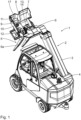
- a toy vehicle 1 is designed as a forklift truck with a chassis with a steerable rear axle.
- the toy vehicle 1 has a fork arm 2 with a holding component 3 designed as a cantilever arm, which can be pivoted relative to a vehicle frame 4 of the toy vehicle 1 .
- a fork 5 of the fork arm 2 with fork tines 6a represents a supporting component of the toy vehicle 1.
- This supporting component 5 is relative to the holding component 3 can be tilted about a tilting bearing with a tilting joint axis 6 running horizontally and perpendicularly to the direction of travel of the toy vehicle 1 .
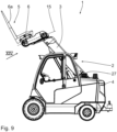
- FIGS. 1 and 2 show a maximum lowered and example the 9 shows a maximum raised tilt position of the support component 5, so the fork.
- a tilting bearing assembly 7 is used to specify the tilting positions of the tiltable support component 5 of the toy vehicle 1.
- the latter also includes a tilting locking device 8, which is described below with reference to Figures 1 and detailed illustrations according to Figures Figures 10 to 15 is explained in more detail.
- the tilt locking device 8 is used to lock the support component 5 in one of several selectable tilt positions relative to the holding component 3.
- the tilt locking device 8 has a tilt locking body 9 which is designed as an actuating lever and is itself designed to be tiltable about a lever joint with a lever axis 10 .
- the toggle bolt body 9 is mounted on the support component 5 via this lever joint.
- the toggle latch body 9 has an actuating arm with an actuating section 11 accessible from the outside and a latch arm which is opposite in relation to the lever axis 10 and has a latch section 12.
- the actuating section 11 is an integral part of the toggle latch body 9.
- the latch section 12 is an integral part of the toggle bolt body 9.
- the tilting locking device 8 also has a tilting counter-locking body 13 which is fixed to the holding component 3 .
- the tilting counter-bar body 13 has a counter-bar section 14.
- the two bar sections 12, 14 are designed as mutually complementary tilting-bar toothings running radially to the tilting joint axis 6.
- the lever axis 10 is oriented in such a way that the toggle bolt body 9 can be pivoted in a pivot plane 15 (cf. 9 ) performed, in which the tilting joint axis 6 is located.
- the tilting bolt body 9 is displaceable between one in the Figures 12 to 15 shown release position and an example in the figures 1 , 10 and 11 illustrated locking position.
- the locking section 12 of the tilting latch body 9 is released from the counter-latching section 14 of the tilting counter-latching body 13 for the tilting displacement of the support component 5 relative to the lifting component 3 about the tilting joint axis 6.
- the toothing of the locking section 12 of the tilting locking body 9 on the one hand and the counter-locking section 14 of the tilting counter-locking body 13 engage with one another, i.e. the tilting locking body 9 with the tilting counter-locking body 13 for fixing a selected Tilt position is locked.
- a compression spring 16 (cf. 11 ), which is mounted in the support component 5, the tilting bolt body 9 is pretensioned in the locked position.
- the compression spring 16 is in a sleeve section 17 (cf. 10 ) recorded, which is specified by the tilting bolt body 9.
- the sleeve section 17 is an integral part of the toggle bolt body 9.
- the support component 5, ie the fork can be tilted about the tilting joint axis 6 relative to the holding component 3, ie to the cantilever arm.
- a relative displacement of the tilting bolt body 9 to the tilting counterbolt body 13 that takes place here between locking positions that specify different tilting positions of the support component 5 relative to the holding component 3 takes place by pivoting the tilting bolt body relative to the tilting counterbolt body 13 and the tilting Joint axis 6.
- Various such tilt positions are in the figures 2 and 9 shown.
- a pivot bearing with bearing bolts 19 is used.
- the pivot joint axis 18 runs parallel to the tilt joint axis 6.
- a pivoting locking device 20 which is described below in particular with reference to FIG Figures 4 to 8 is explained, is used to lock the holding component 3 in at least one pivoted position relative to the vehicle frame 4.
- the swing lock device 20 has a swing bolt body 21 and a swing counter-bolt body 22 which is an integral part of the holding component 3 .
- the swivel bolt body 21 is linearly parallel to the pivot joint axis 18 displaceable between a release position in the figures 6 and 7 is shown and a locked position, in particular in the figures 5 and 8th is shown.
- the pivoting bolt body 21 comes from the pivoting counterbolt body 22 for the tilting displacement of the holding component 3 relative to the vehicle frame 4 about the pivot joint axis 18 freely.
- the locking sections 23 , 24 of the pivoting locking device 20 can in turn be designed as pivoting locking toothings running radially to the pivoting joint axis 18 .
- actuating element 26 For the displacement movement of the swivel bolt body 21 between the locking position and the release position along a displacement direction (cf. arrow 25 in 4 ) serves an actuating element 26, which has an actuating section 27, which is accessible from above and is designed as a rotary knob.
- the actuating element 26 can be pivoted about an actuating pivot axis 28 to actuate the pivot bolt body 21 , which is perpendicular to the displacement direction 25 and also perpendicular to the pivot joint axis 18 .
- the actuating element 26 has an actuating body 29.
- the latter has an outer periphery 30 about the actuating pivot axis 28, the peripheral contour of which deviates from a rotational symmetry about the actuating pivot axis 28.
- the actuating body 29 interacts with a counter-stop 31 of the pivoting bolt body 21 .
- This counter-stop 31 is designed as a through-opening in the swivel-bolt body 21 for the actuating element 26 .
- the swivel bolt body 21 is prestressed in the bolted position by a compression spring 32 .
- the compression spring 32 is accommodated in a spring sleeve 33 of a frame component 34 of the vehicle frame 4 .
- the compression spring 32 is slipped onto a spring lug 35 which forms an integral part of the pivoting bolt body 21 .
- tilted positions of the support component 5, ie the fork, to the holding component 3, ie to the boom of the toy vehicle, and on the other hand different tilted positions of the holding component 3 to the vehicle frame can be specified.
- the tilting latch body 9 is actuated via the actuating section 11, so that it moves from the latched position into the release position.
- the support component 5 can then be tilted about the tilting joint axis 6 relative to the holding component 3 .
- the actuating element 26 is moved out of the locked position by the actuating section 27 figures 4 and 5 90° clockwise to the release position, for example after the figures 6 and 7 twisted.
- the actuating body 29 of the actuating element 26 takes the counter-stop 31 of the pivoting bolt body 21 against the pretension of the compression spring 32 so that it is transferred from the bolted position to the release position and disengages from the pivoting counter-bolt body 22 .
- the holding component 3 can then be tilted freely relative to the vehicle frame 4 within the specified movement limits about the pivot joint axis 18 .
Landscapes
- Toys (AREA)
Description
- Die vorliegende Patentanmeldung nimmt die Priorität der deutschen Patentanmeldung
DE 10 2020 216 589.0 in Anspruch. - Die Erfindung betrifft ein Spielfahrzeug mit zueinander verkipp- bzw. verschwenkbaren Komponenten.
- Derartige Spielfahrzeuge sind in vielfacher Ausführung beispielsweise in Form von Spielzeug-Gabelstaplern oder Spielzeug-Baggern bekannt. Ein Beispiel hierfür liefert die
EP 3 047 887 A1 . DieDE 1 111 078 A offenbart eine Vorrichtung zum Heben und Senken beweglicher Teile von Spielfahrzeugen, insbesondere Kipplastwagen. - Es ist eine Aufgabe der vorliegenden Erfindung, eine Verkippbarkeit und/oder eine Schwenkbarkeit einer Komponente eines Spielfahrzeugs so zu ermöglichen, dass sich hierüber verschiedene für den Spielfahrzeug-Benutzer interessante Betriebsstellungen des Spielfahrzeugs ergeben.
- Diese Aufgabe ist erfindungsgemäß gelöst durch ein Spielfahrzeug mit den im Anspruch 1 angegebenen Merkmalen.
- Erfindungsgemäß wurde erkannt, dass eine Kipplagerungs-Baugruppe mit einer Kipp-Verriegelungseinrichtung die Möglichkeit schafft, je nach Spielbedürfnis die verkippbare Tragkomponente einerseits in eine von mehreren möglichen Kippstellungen umzustellen und andererseits die Möglichkeit schafft, die Tragkomponente in einer ausgewählten Kippstellung zu verriegeln, um hierüber beispielsweise Lasten sicher mit der Tragkomponente tragen zu können. Die Ausführung des Kipp-Riegelkörpers als betätigbarer Kipphebel schafft die Möglichkeit, einerseits Kippstellungen der verkippbaren Tragkomponente und, falls möglich, andererseits eine Kipp- bzw. Schwenkstellungen der Haltekomponente relativ zu einem Fahrzeugrahmen des Spielfahrzeugs mit Hilfe eines Betätigungselementes vorzugeben. Somit ist eine Einhand-Bedienung der verkippbaren Tragkomponente und ggf. der Haltekomponente möglich. Beim Kipp-Riegelkörper kann es sich um eine zur verkippbaren Tragkomponente und auch zur Haltekomponente separate Komponente handeln. Eine Verlagerungsbewegung des Kipp-Riegelkörpers kann gelagert in einer Kipplagerungs-Baugruppe erfolgen, zu der das Kipplager und die Kipp-Verriegelungseinrichtung gehören. Bei der Kipplagerungs-Baugruppe kann es sich um eine einerseits von der Tragkomponente und andererseits von der Haltekomponente separate Komponenten-Baugruppe des Spielfahrzeugs handeln.
- Insbesondere ist der Kipp-Riegelkörper kein einstückiger Bestandteil der Tragkomponente und/oder der Haltekomponente des Spielfahrzeugs.
- Das Spielfahrzeug kann insbesondere als Gabelstapler ausgeführt sein. Die verkippbare Tragkomponente kann als Gabel des Gabelstaplers ausgeführt sein. Wenn einerseits die Tragkomponente und andererseits die Haltekomponente verkipp- bzw. verschwenkbar sind, ist es möglich, beispielsweise die Gabel in einer Wunsch-Kippwinkelstellung zu halten und die Haltekomponente, die dann als Auslegerarm gestaltet sein kann, gleichzeitig zu verschwenken.
- Die Kipp-Gelenkachse, um die die Tragkomponente relativ zur Haltekomponente des Spielfahrzeugs verkippbar ist, kann senkrecht zur Fahrtrichtung des Spielfahrzeugs verlaufen. Bei der Haltekomponente kann es sich um einen Auslegerarm zum Halten einer Spielfahrzeug-Funktionskomponente, beispielsweise einer Gabel oder einer Baggerschaufel, handeln. Eine Umstellung des Kipp-Riegelkörpers zwischen der Riegelstellung und der Freigabestellung kann durch direkte Betätigung des Kipp-Riegelkörpers erfolgen, also so, dass eine spielende Person den Kipp-Riegelkörper direkt manuell betätigt. Die Ausführung des Kipp-Riegelkörpers als Kipphebel ist baulich einfach zu realisieren.
- Das Spielfahrzeug kann insgesamt aus Kunststoff und kann insbesondere insgesamt aus Spritzgussteilen hergestellt sein.
- Bei einer Gestaltung nach Anspruch 2 bewegen sich die beiden Riegelkörper relativ zueinander um die Kipp-Gelenkachse, was zu einer einfachen mechanischen Realisierung der Riegelmechanik führt.
- Eine Verschwenkgeometrie des Kipp-Riegelkörpers nach Anspruch 3 führt zu einer sicheren Umstellung des Kipp-Riegelkörpers zwischen der Freigabe- und der Riegelstellung.
- Eine Kipp-Riegelverzahnung nach Anspruch 4 führt zu einer sicheren Verriegelung der Kipp-Verriegelungseinrichtung.
- Eine Druckfeder nach Anspruch 5 erleichtert eine Umstellung des Kipp-Riegelkörpers zwischen der Freigabe- und der Riegelstellung und führt zudem zu einer sicheren Fixierung der Tragkomponente, soweit keine Betätigung des Kipp-Riegelkörpers erfolgt. Die Aufnahme der Druckfeder in einem Hülsenabschnitt des Kipp-Riegelkörpers schützt die Druckfeder.
- Eine Schwenk-Verrieglungseinrichtung nach Anspruch 6 ermöglicht eine betriebssichere Verriegelung der Haltekomponente, wobei die Verriegelung bei Bedarf durch entsprechende Verlagerung des Schwenk-Riegelkörpers gelöst werden kann. Die lineare Verlagerung des Schwenk-Riegelkörpers lässt sich baulich einfach realisieren und ermöglicht gleichzeitig eine sichere Verriegelung. Die Verlagerungsrichtung des Schwenk-Riegelkörpers parallel zur Schwenk-Gelenkachse führt zu einer effektiven Verriegelung bzw. Entriegelung.
- Ein Betätigungselement nach Anspruch 7 gewährleistet eine komfortable und sichere Umstellung des Schwenk-Riegelkörpers. Dies gilt besonders für eine Ausführung des Betätigungselements nach Anspruch 8. Der Gegenanschlag kann dabei durch eine Durchtrittsöffnung des Schwenk-Riegelkörpers für das Betätigungselement ausgeführt sein.
- Eine Vorspannung des Schwenk-Riegelkörpers nach Anspruch 9 ermöglicht eine Verriegelung der Schwenk-Riegelungseinrichtung, soweit diese nicht betätigt wird. Die Vorspannung kann über eine Druckfeder erfolgen. Die Druckfeder kann in einer Federhülse aufgenommen sein, die beispielsweise einen Abschnitt des Fahrzeugrahmens darstellen kann. Über eine solche Federhülse ist die Druckfeder geschützt.
- Ein Ausführungsbeispiel der Erfindung wird nachfolgend an der Zeichnung näher erläutert. Diese zeigen:
- Fig. 1
- perspektivisch ein als Gabelstapler ausgeführtes Spielfahrzeug mit einem schwenkbaren, seinerseits im Bereich einer Gabel verkippbaren Gabel-Ausleger;
- Fig. 2
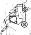
- eine Seitenansicht des Spielfahrzeugs nach
Fig. 1 , wobei die Gabel als Tragkomponente des Spielfahrzeugs relativ zu einer angehobenen Ausleger-Haltekomponente maximal abgesenkt gekippt ist; - Fig. 3
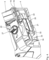
- eine perspektivische, rückseitige Detailansicht des Spielfahrzeugs mit einer Schwenk-Verriegelungseinrichtung zur Verriegelung der Ausleger-Haltekomponente in einer Riegelstellung;
- Fig. 4
- eine innere Details preisgebende Schnittdarstellung aus der rückseitigen Perspektive nach
Fig. 3 entsprechend der Schnittlinie IV-IV inFig. 2 ; - Fig. 5
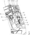
- in einer der
Fig. 4 entsprechenden Perspektivansicht einen Schnitt gemäß Linie V-V inFig. 2 ; - Fig. 6
- in einer zu
Fig. 5 ähnlichen Darstellung die Schwenk-Verriegelungseinrichtung in einer Freigabestellung eines Schwenk-Riegelkörpers; - Fig. 7
- in einer zu
Fig. 6 ähnlichen Ansicht einen Schnitt gemäß Linie VII-VII inFig. 2 , wiederum in der Freigabestellung der Schwenk-Verriegelungseinrichtung; - Fig. 8
- eine Aufsicht auf das schräg gemäß Schnittlinie VIII-VIII in
Fig. 2 geschnittene Spielfahrzeug; - Fig. 9
- eine weitere Seitenansicht des Spielfahrzeugs mit der maximal angehobenen Gabel des Spielfahrzeugs;
- Fig. 10
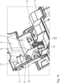
- eine Detailansicht auf eine Kipp-Verriegelungseinrichtung zur Verriegelung der Gabel relativ zur Haltekomponente, gesehen in etwa aus Blickrichtung X in
Fig. 2 , wobei ein Kipp-Riegelkörper mit einem Kipp-Gegen-Riegelkörper in einer Riegelstellung verriegelt ist; - Fig. 11
- die Kipp-Verriegelungseinrichtung nach
Fig. 10 in einem Schnitt gemäß Linie XI-XI inFig. 2 ; - Fig. 12
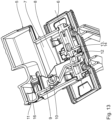
- die Kipp-Verriegelungseinrichtung nach
Fig. 10 in einer Freigabestellung eines Kipp-Riegelkörpers relativ zu einem Kipp-Gegen-Riegelkörper; - Fig. 13
- die Kipp-Verriegelungseinrichtung in der Freigabestellung nach
Fig. 12 , gesehen in einem Schnitt wie inFig. 11 ; - Fig. 14
- die Kipp-Verriegelungseinrichtung in einer Detailansicht und in der Riegelstellung, gesehen aus Blickrichtung XIV in
Fig. 9 ; und - Fig. 15
- in einer zu
Fig. 14 ähnlichen Ansicht die Kipp-Verriegelungseinrichtung in der Freigabestellung. - Ein Spielfahrzeug 1 ist als Gabelstapler mit einem Fahrwerk mit lenkbarer Hinterachse ausgestaltet. Das Spielfahrzeug 1 hat einen Gabel-Ausleger 2 mit einer als Auslegerarm ausgestalteten Haltekomponente 3, die relativ zu einem Fahrzeugrahmen 4 des Spielfahrzeugs 1 schwenkbar ist. Eine Gabel 5 des Gabel-Auslegers 2 mit Gabelzinken 6a stellt eine Tragkomponente des Spielfahrzeugs 1 dar. Diese Tragkomponente 5 ist relativ zur Haltekomponente 3 um ein Kipplager mit horizontal und senkrecht zur Fahrtrichtung des Spielfahrzeugs 1 verlaufender Kipp-Gelenkachse 6 verkippbar.
-
Figuren 1 und2 zeigen eine maximal abgesenkte und beispielsweise dieFig. 9 zeigt eine maximal angehobene Kippstellung der Tragkomponente 5, also der Gabel. - Zur Vorgabe von Kippstellungen der verkippbaren Tragkomponente 5 des Spielfahrzeugs 1 dient eine Kipplagerungs-Baugruppe 7. Zu letzterer gehört neben dem Kipplager mit der Kipp-Gelenkachse 6 noch eine Kipp-Verrieglungseinrichtung 8, die nachfolgend unter Bezugnahme auf die Figuren 1 sowie Detaildarstellungen nach den
Figuren 10 bis 15 näher erläutert wird. - Die Kipp-Verrieglungseinrichtung 8 dient zur Verriegelung der Tragkomponente 5 in einer von mehreren wählbaren Kippstellungen relativ zur Haltekomponente 3. Die Kipp-Verriegelungseinrichtung 8 hat einen Kipp-Riegelkörper 9, der als Betätigungshebel ausgeführt ist und selbst um ein Hebelgelenk mit Hebelachse 10 kippbar gestaltet ist. Der Kipp-Riegelkörper 9 ist über dieses Hebelgelenk an der Tragkomponente 5 gelagert. Der Kipp-Riegelkörper 9 hat einen Betätigungsarm mit einem von außen zugänglichen Betätigungsabschnitt 11 und einem in Bezug auf die Hebelachse 10 gegenüberliegenden Riegelarm mit einem Riegelabschnitt 12. Der Betätigungsabschnitt 11 ist ein einstückiger Bestandteil des Kipp-Riegelkörpers 9. Der Riegelabschnitt 12 ist ein einstückiger Bestandteil des Kipp-Riegelkörpers 9.
- Die Kipp-Verriegelungseinrichtung 8 hat weiterhin einen Kipp-Gegen-Riegelkörper 13, der an der Haltekomponente 3 festgelegt ist. Der Kipp-Gegen-Riegelkörper 13 hat einen Gegen-Riegelabschnitt 14. Die beiden Riegelabschnitte 12, 14 sind als zueinander komplementäre, radial zur Kipp-Gelenkachse 6 verlaufende Kipp-Riegel-Verzahnungen ausgebildet.
- Die Hebelachse 10 ist so orientiert, dass der Kipp-Riegelkörper 9 zum Verschwenken in einer Schwenkebene 15 (vgl.
Fig. 9 ) ausgeführt, in der die Kipp-Gelenkachse 6 liegt. - Der Kipp-Riegelkörper 9 ist verlagerbar zwischen einer in den
Figuren 12 bis 15 dargestellten Freigabestellung und einer beispielsweise in denFiguren 1 ,10 und11 dargestellten Riegelstellung. In der Freigabestellung des Kipp-Riegelkörpers 9 kommt der Riegelabschnitt 12 des Kipp-Riegelkörpers 9 vom Gegen-Riegelabschnitt 14 des Kipp-Gegen-Riegelkörpers 13 zur Kippverlagerung der Tragkomponente 5 relativ zur Hubkomponente 3 um die Kipp-Gelenkachse 6 frei. In der Riegelstellung greifen die Verzahnungen des Riegelabschnitts 12 des Kipp-Riegelkörpers 9 einerseits und des Gegen-Riegelabschnitts 14 des Kipp-Gegen-Riegelkörpers 13 ineinander ein, also dass der Kipp-Riegelkörper 9 mit dem Kipp-Gegen-Riegelkörper 13 zur Fixierung einer gewählten Kippstellung verriegelt ist. - Über eine Druckfeder 16 (vgl.
Fig. 11 ), die in der Tragkomponente 5 gelagert ist, ist der Kipp-Riegelkörper 9 in der Riegelstellung vorgespannt. Die Druckfeder 16 ist in einem Hülsenabschnitt 17 (vgl.Fig. 10 ) aufgenommen, der vom Kipp-Riegelkörper 9 vorgegeben ist. Der Hülsenabschnitt 17 ist ein einstückiger Bestandteil des Kipp-Riegelkörpers 9. - In der Freigabestellung kann die Tragkomponente 5, also die Gabel, relativ zur Haltekomponente 3, also zum Auslegerarm, um die Kipp-Gelenkachse 6 verkippt werden. Eine hierbei erfolgende Relativverlagerung des Kipp-Riegelkörpers 9 zum Kipp-Gegen-Riegelkörper 13 zwischen Riegelstellungen, die verschiedene Kippstellungen der Tragkomponente 5 relativ zur Haltekomponente 3 vorgeben, erfolgt durch Schwenken des Kipp-Riegelkörpers relativ zum Kipp-Gegen-Riegelkörper 13 und die Kipp-Gelenkachse 6. Verschiedene derartige Kippstellungen sind in den
Figuren 2 und9 dargestellt. - Zur Vorgabe einer horizontal verlaufenden Schwenk-Gelenkachse 18 (vgl.
Fig. 4 ), um die die Haltekomponente 3 relativ zum Fahrzeugrahmen 4 des Spielfahrzeugs 1 verschwenkbar ist, dient ein Schwenklager mit Lagerbolzen 19. Die Schwenk-Gelenkachse 18 verläuft parallel zur Kipp-Gelenkachse 6. - Eine Schwenk-Verriegelungseinrichtung 20, die nachfolgend insbesondere unter Bezugnahme auf die
Figuren 4 bis 8 erläutert wird, dient zur Verriegelung der Haltekomponente 3 in mindestens einer Schwenkstellung relativ zum Fahrzeugrahmen 4. - Die Schwenk-Verrieglungseinrichtung 20 hat einen Schwenk-Riegelkörper 21 und einen Schwenk-Gegen-Riegelkörper 22, der ein einstückiger Bestandteil der Haltekomponente 3 ist. Der Schwenk-Riegelkörper 21 ist linear parallel zur Schwenk-Gelenkachse 18 verlagerbar zwischen einer Freigabestellung, die in den
Figuren 6 und7 dargestellt ist und einer Riegelstellung, die insbesondere in denFiguren 5 und8 dargestellt ist. In der Freigabestellung kommt der Schwenk-Riegelkörper 21 vom Schwenk-Gegen-Riegelkörper 22 zur Kippverlagerung der Haltekomponente 3 relativ zum Fahrzeugrahmen 4 um die Schwenk-Gelenkachse 18 frei. In der Riegelstellung rückt ein Riegelabschnitt 23 (vgl.Fig. 8 ) des Schwenk-Riegelkörpers 21 in einen komplementär hierzu ausgebildeten Gegen-Riegelabschnitt 24 des Schwenk-Gegen-Riegelkörpers 22 ein zur Fixierung einer gewählten Schwenkstellung der Haltekomponente 3. - Die Riegelabschnitte 23, 24 der Schwenk-Verriegelungseinrichtung 20 können wiederum als radial zur Schwenk-Gelenkachse 18 verlaufende Schwenk-Riegelverzahnungen ausgebildet sein.
- Zur Verlagerungsbewegung des Schwenk-Riegelkörpers 21 zwischen der Riegelstellung und der Freigabestellung längs einer Verlagerungsrichtung (vgl. Pfeil 25 in
Fig. 4 ) dient ein Betätigungselement 26, das einen von oben her zugänglichen, als Drehknopf ausgebildeten Betätigungsabschnitt 27 aufweist. Das Betätigungselement 26 ist zur Betätigung des Schwenk-Riegelkörpers 21 um eine Betätigungs-Schwenkachse 28 schwenkbar, die senkrecht auf der Verlagerungsrichtung 25 und auch senkrecht auf der Schwenk-Gelenkachse 18 steht. Das Betätigungselement 26 hat einen Betätigungskörper 29. Letzterer hat einen Außenumfang 30 um die Betätigungs-Schwenkachse 28, dessen Umfangskontur von einer Rotationssymmetrie um die Betätigungs-Schwenkachse 28 abweicht. Zur Betätigung des Schwenk-Riegelkörpers 21 wirkt der Betätigungskörper 29 mit einem Gegenanschlag 31 des Schwenk-Riegelkörpers 21 zusammen. Dieser Gegenanschlag 31 ist als Durchtrittsöffnung des Schwenk-Riegelkörpers 21 für das Betätigungselement 26 ausgeführt. - Der Schwenk-Riegelkörper 21 ist in der Riegelstellung über eine Druckfeder 32 vorgespannt. Die Druckfeder 32 ist in einer Federhülse 33 einer Rahmenkomponente 34 des Fahrzeugrahmens 4 aufgenommen. Zur Positionssicherung der Druckfeder 32 relativ zum Schwenk-Riegelkörper 21 ist die Druckfeder 32 auf eine Federnase 35 aufgesteckt, die einen einstückigen Bestandteil des Schwenk-Riegelkörpers 21 bildet.
- Beim Spielen können verschiedene Kippstellungen einerseits der Tragkomponente 5, also der Gabel, zur Haltekomponente 3, also zum Ausleger des Spielfahrzeugs, und andererseits verschiedene Kippstellungen der Haltekomponente 3 zum Fahrzeugrahmen vorgegeben werden. Zur Kippstellungsvorgabe der Tragkomponente 5 wird über den Betätigungsabschnitt 11 der Kipp-Riegelkörper 9 betätigt, sodass er von der Riegelstellung in die Freigabestellung ausrückt. In der Freigabestellung des Kipp-Riegelkörpers 9 kann die Tragkomponente 5 dann relativ zur Haltekomponente 3 um die Kipp-Gelenkachse 6 verkippt werden.
- Wenn die Haltekomponente 3 um die Schwenk-Gelenkachse 18 verkippt, also in eine andere Kippstellung verbracht werden soll, wird über den Betätigungsabschnitt 27 das Betätigungselement 26 aus der Riegelstellung nach den
Figuren 4 und5 um 90° im Uhrzeigersinn in die Freigabestellung beispielsweise nach denFiguren 6 und7 verdreht. Hierbei nimmt der Betätigungskörper 29 des Betätigungselements 26 entgegen der Vorspannung der Druckfeder 32 den Gegenanschlag 31 des Schwenk-Riegelkörpers 21 mit, sodass dieser von der Riegelstellung in die Freigabestellung überführt wird und aus den Schwenk-Gegen-Riegelkörper 22 ausrückt. Die Haltekomponente 3 kann dann frei zum Fahrzeugrahmen 4 innerhalb der vorgegeben Bewegungsgrenzen um die Schwenk-Gelenkachse 18 verkippt werden.
Claims (9)
- Spielfahrzeug (1) mit einer Kipplagerungs-Baugruppe (7) zur Vorgabe von Kippstellungen einer verkippbaren Tragkomponente (5) des Spielfahrzeugs (1),- mit einem Kipplager zur Vorgabe einer horizontal verlaufenden Kipp-Gelenkachse (6), um die die Tragkomponente (5) relativ zu einer Haltekomponente (3) des Spielfahrzeugs (1) verkippbar ist,- mit einer Kipp-Verriegelungseinrichtung (8) zur Verriegelung der Tragkomponente (5) in einer von mehreren wählbaren Kippstellungen relativ zur Haltekomponente (3), aufweisend einen Kipp-Riegelkörper (9) und einen Kipp-Gegen-Riegelkörper (13),- wobei der Kipp-Riegelkörper (9) verlagerbar ist zwischen-- einer Freigabestellung, in der der Kipp-Riegelkörper (9) vom Kipp-Gegen-Riegelkörper (13) zur Kippverlagerung der Tragkomponente (5) relativ zur Haltekomponente (3) um die Kipp-Gelenkachse (6) freikommt, und-- einer Riegelstellung, in der der Kipp-Riegelkörper (9) mit dem Kipp-Gegen-Riegelkörper (13) zur Fixierung der gewählten Kippstellung verriegelt ist,- dadurch gekennzeichnet, dass der Kipp-Riegelkörper (9) in die Riegelstellung vorgespannt ist und als betätigbarer Kipphebel ausgeführt und selbst um eine Hebelachse (10) kippbar gestaltet ist.
- Spielfahrzeug nach Anspruch 1, dadurch gekennzeichnet, dass die Kipp-Verriegelungseinrichtung (8) so ausgeführt ist, dass eine Relativverlagerung des Kipp-Riegelkörpers (9) zum Kipp-Gegen-Riegelkörper (13) zwischen verschiedene Kippstellungen vorgebenden Riegelstellungen durch Schwenken des Kipp-Riegelkörpers (9) um die Kipp-Gelenkachse (6) erfolgt.
- Spielfahrzeug nach Anspruch 1 oder 2, dadurch gekennzeichnet, dass der Kipp-Riegelkörper (9) zum Verschwenken in einer Schwenkebene (15) ausgeführt ist, in der die Kipp-Gelenkachse (6) liegt.
- Spielfahrzeug nach einem der Ansprüche 1 bis 3, dadurch gekennzeichnet, dass ein Riegelabschnitt (12, 14) des Kipp-Riegelkörpers (9) und/oder des Kipp-Gegen-Riegelkörpers (13) mit einer radial zur Kipp-Gelenkachse (6) verlaufenden Kipp-Riegel-Verzahnung ausgebildet ist.
- Spielfahrzeug nach einem der Ansprüche 1 bis 4, gekennzeichnet durch eine Druckfeder (16) zur Vorspannung des Kipp-Riegelkörpers (9) in der Riegelstellung, die in einem vom Kipp-Riegelkörper (9) vorgegebenen Hülsenabschnitt (17) aufgenommen ist.
- Spielfahrzeug nach einem der Ansprüche 1 bis 5, gekennzeichnet durch- ein Schwenklager zur Vorgabe einer horizontal verlaufenden Schwenk-Gelenkachse (18), um die die Haltekomponente (3) relativ zu einem Fahrzeugrahmen (4) des Spielfahrzeugs (1) verschwenkbar ist,- eine Schwenk-Verriegelungseinrichtung (20) zur Verriegelung der Haltekomponente (3) in einer Schwenkstellung relativ zum Fahrzeugrahmen (4), aufweisend einen Schwenk-Riegelkörper (21) und einen Schwenk-Gegen-Riegelkörper (22),- wobei der Schwenk-Riegelkörper (21) verlagerbar ist zwischen-- einer Freigabestellung, in der der Schwenk-Riegelkörper (21) vom Schwenk-Gegen-Riegelkörper (22) zur Kippverlagerung der Haltekomponente (3) relativ zum Fahrzeugrahmen (4) um die Schwenk-Gelenkachse (18) freikommt, und-- einer Riegelstellung, in der der Schwenk-Riegelkörper (21) mit dem Schwenk-Gegen-Riegelkörper (22) zur Fixierung der gewählten Schwenkstellung verriegelt ist,- wobei eine Verlagerungsrichtung (25) des Schwenk-Riegelkörpers (21) linear und parallel zur Schwenk-Gelenkachse (18) verläuft.
- Spielfahrzeug nach Anspruch 6, gekennzeichnet durch ein Betätigungselement (26) zur Verlagerungsbewegung des Schwenk-Riegelkörpers (21) in der Verlagerungsrichtung (25), ausgeführt als vom Schwenk-Riegelkörper (21) separate Komponente, die zur Betätigung schwenkbar ist, um eine Betätigungs-Schwenkachse (28), die senkrecht auf der Verlagerungsrichtung (25) steht.
- Spielfahrzeug nach Anspruch 7, dadurch gekennzeichnet, dass das Betätigungselement (26) einen Betätigungskörper (29) mit einem Außenumfang (30) um die Betätigungs-Schwenkachse (28) aufweist, der von einer Rotationssymmetrie abweicht und zur Betätigung des Schwenk-Riegelkörpers (21) mit einem Gegenanschlag (31) des Schwenk-Riegelkörpers (21) zusammenwirkt.
- Spielfahrzeug nach einem der Ansprüche 6 bis 8, dadurch gekennzeichnet, dass der Schwenk-Riegelkörper (21) in die Riegelstellung vorgespannt ist.
Applications Claiming Priority (1)
| Application Number | Priority Date | Filing Date | Title |
|---|---|---|---|
| DE102020216589.0A DE102020216589A1 (de) | 2020-12-30 | 2020-12-30 | Spielfahrzeug |
Publications (2)
| Publication Number | Publication Date |
|---|---|
| EP4023312A1 EP4023312A1 (de) | 2022-07-06 |
| EP4023312B1 true EP4023312B1 (de) | 2023-07-12 |
Family
ID=78821756
Family Applications (1)
| Application Number | Title | Priority Date | Filing Date |
|---|---|---|---|
| EP21212281.6A Active EP4023312B1 (de) | 2020-12-30 | 2021-12-03 | Spielfahrzeug |
Country Status (3)
| Country | Link |
|---|---|
| EP (1) | EP4023312B1 (de) |
| DE (1) | DE102020216589A1 (de) |
| PL (1) | PL4023312T3 (de) |
Family Cites Families (7)
| Publication number | Priority date | Publication date | Assignee | Title |
|---|---|---|---|---|
| DE1111078B (de) * | 1959-02-21 | 1961-07-13 | Dr Hermann Neuhierl | Vorrichtung zum Heben und Senken beweglicher Teile von Spielfahrzeugen, insbesondere Kipplastwagen |
| US4236344A (en) * | 1978-12-04 | 1980-12-02 | Mattel, Inc. | Toy with spring-operated speed regulated motor mechanism |
| DE29804491U1 (de) * | 1998-03-13 | 1998-05-20 | Bruder Spielwaren GmbH & Co. KG, 90768 Fürth | Spielzeugfahrzeug |
| DE20001819U1 (de) * | 2000-02-02 | 2000-03-30 | Bruder Spielwaren GmbH & Co. KG, 90768 Fürth | Spielzeugfahrzeug nach Art eines Baggerladers |
| DE20001760U1 (de) | 2000-02-02 | 2000-03-30 | Bruder Spielwaren GmbH & Co. KG, 90768 Fürth | Verbindungselement für ein Zuatzaggregat eines Spielzeugfahrzeuges |
| DE202015100264U1 (de) | 2015-01-21 | 2016-04-25 | Bruder Spielwaren Gmbh + Co. Kg | Spielfahrzeug-Bagger |
| DE102019201054B3 (de) * | 2019-01-28 | 2020-02-13 | Bruder Spielwaren Gmbh + Co. Kg | Baggerschaufel-Baugruppe |
-
2020
- 2020-12-30 DE DE102020216589.0A patent/DE102020216589A1/de not_active Withdrawn
-
2021
- 2021-12-03 PL PL21212281.6T patent/PL4023312T3/pl unknown
- 2021-12-03 EP EP21212281.6A patent/EP4023312B1/de active Active
Also Published As
| Publication number | Publication date |
|---|---|
| PL4023312T3 (pl) | 2023-12-18 |
| EP4023312A1 (de) | 2022-07-06 |
| DE102020216589A1 (de) | 2022-06-30 |
Similar Documents
| Publication | Publication Date | Title |
|---|---|---|
| DE19516876C1 (de) | Antriebsanordnung zum Bewegen eines verriegelbaren Fahrzeugteils | |
| DE4345524C2 (de) | Überrollschutzsystem | |
| EP3904129B1 (de) | Anhängekupplung | |
| EP1741572A1 (de) | Anhängevorrichtung | |
| DE2727270A1 (de) | Schwenkbares steuer fuer kraftfahrzeuge | |
| DE102022205078B3 (de) | Verstelleinrichtung für ein Lenkrad eines Kraftfahrzeugs | |
| DE4128460C2 (de) | Dachanordnung für ein Kraftfahrzeug | |
| EP1295753B1 (de) | Gelenkbeschlag für einen Kraftfahrzeugsitz mit vorkippbarer Rückenlehne | |
| EP3554931B1 (de) | Lenkeinheit für ein fahrzeug und fahrzeug, insbesondere elektroroller | |
| EP2199502B1 (de) | Kraftfahrzeugschloss | |
| WO1997028020A1 (de) | Vorrichtung zur verriegelung eines containers an einem fahrzeugchassis | |
| EP4023312A1 (de) | Spielfahrzeug | |
| DE4313570A1 (de) | Sicherheitsverriegelung für Fahrzeugabdeckungen | |
| DE102009009595A1 (de) | Verschlusssystem für ein Verdeck eines Cabriolet-Fahrzeugs | |
| EP4023313B1 (de) | Spielfahrzeug | |
| DE102008059355A1 (de) | Beschlagsystem für einen Fahrzeugsitz | |
| EP1179109B1 (de) | Kraftfahrzeug-türschloss | |
| DE4319497B4 (de) | Innere Türöffnungsvorrichtung an einem Kraftfahrzeug | |
| EP0876937B1 (de) | Crash-Verriegelung | |
| EP0968869B1 (de) | Selbstfahrende landwirtschaftliche Erntemaschine | |
| EP1113132B1 (de) | Elektromotorischer Stellantrieb für ein Kraftfahrzeugschloss | |
| DE19719216C2 (de) | Crash-Verriegelung | |
| EP1378410A2 (de) | Betätigungsvorrichtung für eine Feststellbremse | |
| EP1400644B1 (de) | Fanghakeneinrichtung für eine Fronthaube eines Kraftfahrzeugs | |
| EP1495907A1 (de) | Beschlag für einen Fahrzeugsitz |
Legal Events
| Date | Code | Title | Description |
|---|---|---|---|
| PUAI | Public reference made under article 153(3) epc to a published international application that has entered the european phase |
Free format text: ORIGINAL CODE: 0009012 |
|
| STAA | Information on the status of an ep patent application or granted ep patent |
Free format text: STATUS: THE APPLICATION HAS BEEN PUBLISHED |
|
| AK | Designated contracting states |
Kind code of ref document: A1 Designated state(s): AL AT BE BG CH CY CZ DE DK EE ES FI FR GB GR HR HU IE IS IT LI LT LU LV MC MK MT NL NO PL PT RO RS SE SI SK SM TR |
|
| STAA | Information on the status of an ep patent application or granted ep patent |
Free format text: STATUS: REQUEST FOR EXAMINATION WAS MADE |
|
| 17P | Request for examination filed |
Effective date: 20220816 |
|
| RBV | Designated contracting states (corrected) |
Designated state(s): AL AT BE BG CH CY CZ DE DK EE ES FI FR GB GR HR HU IE IS IT LI LT LU LV MC MK MT NL NO PL PT RO RS SE SI SK SM TR |
|
| GRAP | Despatch of communication of intention to grant a patent |
Free format text: ORIGINAL CODE: EPIDOSNIGR1 |
|
| STAA | Information on the status of an ep patent application or granted ep patent |
Free format text: STATUS: GRANT OF PATENT IS INTENDED |
|
| INTG | Intention to grant announced |
Effective date: 20230228 |
|
| RIN1 | Information on inventor provided before grant (corrected) |
Inventor name: PFEFFERLEIN, MARC |
|
| GRAS | Grant fee paid |
Free format text: ORIGINAL CODE: EPIDOSNIGR3 |
|
| GRAA | (expected) grant |
Free format text: ORIGINAL CODE: 0009210 |
|
| STAA | Information on the status of an ep patent application or granted ep patent |
Free format text: STATUS: THE PATENT HAS BEEN GRANTED |
|
| P01 | Opt-out of the competence of the unified patent court (upc) registered |
Effective date: 20230519 |
|
| AK | Designated contracting states |
Kind code of ref document: B1 Designated state(s): AL AT BE BG CH CY CZ DE DK EE ES FI FR GB GR HR HU IE IS IT LI LT LU LV MC MK MT NL NO PL PT RO RS SE SI SK SM TR |
|
| REG | Reference to a national code |
Ref country code: CH Ref legal event code: EP |
|
| REG | Reference to a national code |
Ref country code: DE Ref legal event code: R096 Ref document number: 502021001000 Country of ref document: DE |
|
| REG | Reference to a national code |
Ref country code: IE Ref legal event code: FG4D Free format text: LANGUAGE OF EP DOCUMENT: GERMAN |
|
| REG | Reference to a national code |
Ref country code: NL Ref legal event code: FP |
|
| REG | Reference to a national code |
Ref country code: LT Ref legal event code: MG9D |
|
| PG25 | Lapsed in a contracting state [announced via postgrant information from national office to epo] |
Ref country code: GR Free format text: LAPSE BECAUSE OF FAILURE TO SUBMIT A TRANSLATION OF THE DESCRIPTION OR TO PAY THE FEE WITHIN THE PRESCRIBED TIME-LIMIT Effective date: 20231013 |
|
| PG25 | Lapsed in a contracting state [announced via postgrant information from national office to epo] |
Ref country code: ES Free format text: LAPSE BECAUSE OF FAILURE TO SUBMIT A TRANSLATION OF THE DESCRIPTION OR TO PAY THE FEE WITHIN THE PRESCRIBED TIME-LIMIT Effective date: 20230712 |
|
| PG25 | Lapsed in a contracting state [announced via postgrant information from national office to epo] |
Ref country code: IS Free format text: LAPSE BECAUSE OF FAILURE TO SUBMIT A TRANSLATION OF THE DESCRIPTION OR TO PAY THE FEE WITHIN THE PRESCRIBED TIME-LIMIT Effective date: 20231112 |
|
| PG25 | Lapsed in a contracting state [announced via postgrant information from national office to epo] |
Ref country code: SE Free format text: LAPSE BECAUSE OF FAILURE TO SUBMIT A TRANSLATION OF THE DESCRIPTION OR TO PAY THE FEE WITHIN THE PRESCRIBED TIME-LIMIT Effective date: 20230712 Ref country code: RS Free format text: LAPSE BECAUSE OF FAILURE TO SUBMIT A TRANSLATION OF THE DESCRIPTION OR TO PAY THE FEE WITHIN THE PRESCRIBED TIME-LIMIT Effective date: 20230712 Ref country code: PT Free format text: LAPSE BECAUSE OF FAILURE TO SUBMIT A TRANSLATION OF THE DESCRIPTION OR TO PAY THE FEE WITHIN THE PRESCRIBED TIME-LIMIT Effective date: 20231113 Ref country code: NO Free format text: LAPSE BECAUSE OF FAILURE TO SUBMIT A TRANSLATION OF THE DESCRIPTION OR TO PAY THE FEE WITHIN THE PRESCRIBED TIME-LIMIT Effective date: 20231012 Ref country code: LV Free format text: LAPSE BECAUSE OF FAILURE TO SUBMIT A TRANSLATION OF THE DESCRIPTION OR TO PAY THE FEE WITHIN THE PRESCRIBED TIME-LIMIT Effective date: 20230712 Ref country code: LT Free format text: LAPSE BECAUSE OF FAILURE TO SUBMIT A TRANSLATION OF THE DESCRIPTION OR TO PAY THE FEE WITHIN THE PRESCRIBED TIME-LIMIT Effective date: 20230712 Ref country code: IS Free format text: LAPSE BECAUSE OF FAILURE TO SUBMIT A TRANSLATION OF THE DESCRIPTION OR TO PAY THE FEE WITHIN THE PRESCRIBED TIME-LIMIT Effective date: 20231112 Ref country code: HR Free format text: LAPSE BECAUSE OF FAILURE TO SUBMIT A TRANSLATION OF THE DESCRIPTION OR TO PAY THE FEE WITHIN THE PRESCRIBED TIME-LIMIT Effective date: 20230712 Ref country code: GR Free format text: LAPSE BECAUSE OF FAILURE TO SUBMIT A TRANSLATION OF THE DESCRIPTION OR TO PAY THE FEE WITHIN THE PRESCRIBED TIME-LIMIT Effective date: 20231013 Ref country code: FI Free format text: LAPSE BECAUSE OF FAILURE TO SUBMIT A TRANSLATION OF THE DESCRIPTION OR TO PAY THE FEE WITHIN THE PRESCRIBED TIME-LIMIT Effective date: 20230712 Ref country code: ES Free format text: LAPSE BECAUSE OF FAILURE TO SUBMIT A TRANSLATION OF THE DESCRIPTION OR TO PAY THE FEE WITHIN THE PRESCRIBED TIME-LIMIT Effective date: 20230712 |
|
| REG | Reference to a national code |
Ref country code: DE Ref legal event code: R097 Ref document number: 502021001000 Country of ref document: DE |
|
| PG25 | Lapsed in a contracting state [announced via postgrant information from national office to epo] |
Ref country code: SM Free format text: LAPSE BECAUSE OF FAILURE TO SUBMIT A TRANSLATION OF THE DESCRIPTION OR TO PAY THE FEE WITHIN THE PRESCRIBED TIME-LIMIT Effective date: 20230712 Ref country code: RO Free format text: LAPSE BECAUSE OF FAILURE TO SUBMIT A TRANSLATION OF THE DESCRIPTION OR TO PAY THE FEE WITHIN THE PRESCRIBED TIME-LIMIT Effective date: 20230712 Ref country code: EE Free format text: LAPSE BECAUSE OF FAILURE TO SUBMIT A TRANSLATION OF THE DESCRIPTION OR TO PAY THE FEE WITHIN THE PRESCRIBED TIME-LIMIT Effective date: 20230712 Ref country code: DK Free format text: LAPSE BECAUSE OF FAILURE TO SUBMIT A TRANSLATION OF THE DESCRIPTION OR TO PAY THE FEE WITHIN THE PRESCRIBED TIME-LIMIT Effective date: 20230712 Ref country code: SK Free format text: LAPSE BECAUSE OF FAILURE TO SUBMIT A TRANSLATION OF THE DESCRIPTION OR TO PAY THE FEE WITHIN THE PRESCRIBED TIME-LIMIT Effective date: 20230712 |
|
| PLBE | No opposition filed within time limit |
Free format text: ORIGINAL CODE: 0009261 |
|
| STAA | Information on the status of an ep patent application or granted ep patent |
Free format text: STATUS: NO OPPOSITION FILED WITHIN TIME LIMIT |
|
| 26N | No opposition filed |
Effective date: 20240415 |
|
| PG25 | Lapsed in a contracting state [announced via postgrant information from national office to epo] |
Ref country code: SI Free format text: LAPSE BECAUSE OF FAILURE TO SUBMIT A TRANSLATION OF THE DESCRIPTION OR TO PAY THE FEE WITHIN THE PRESCRIBED TIME-LIMIT Effective date: 20230712 |
|
| PG25 | Lapsed in a contracting state [announced via postgrant information from national office to epo] |
Ref country code: LU Free format text: LAPSE BECAUSE OF NON-PAYMENT OF DUE FEES Effective date: 20231203 |
|
| PG25 | Lapsed in a contracting state [announced via postgrant information from national office to epo] |
Ref country code: MC Free format text: LAPSE BECAUSE OF FAILURE TO SUBMIT A TRANSLATION OF THE DESCRIPTION OR TO PAY THE FEE WITHIN THE PRESCRIBED TIME-LIMIT Effective date: 20230712 |
|
| REG | Reference to a national code |
Ref country code: BE Ref legal event code: MM Effective date: 20231231 |
|
| PG25 | Lapsed in a contracting state [announced via postgrant information from national office to epo] |
Ref country code: MC Free format text: LAPSE BECAUSE OF FAILURE TO SUBMIT A TRANSLATION OF THE DESCRIPTION OR TO PAY THE FEE WITHIN THE PRESCRIBED TIME-LIMIT Effective date: 20230712 Ref country code: LU Free format text: LAPSE BECAUSE OF NON-PAYMENT OF DUE FEES Effective date: 20231203 |
|
| REG | Reference to a national code |
Ref country code: IE Ref legal event code: MM4A |
|
| PG25 | Lapsed in a contracting state [announced via postgrant information from national office to epo] |
Ref country code: IE Free format text: LAPSE BECAUSE OF NON-PAYMENT OF DUE FEES Effective date: 20231203 |
|
| PG25 | Lapsed in a contracting state [announced via postgrant information from national office to epo] |
Ref country code: BE Free format text: LAPSE BECAUSE OF NON-PAYMENT OF DUE FEES Effective date: 20231231 |
|
| PG25 | Lapsed in a contracting state [announced via postgrant information from national office to epo] |
Ref country code: IE Free format text: LAPSE BECAUSE OF NON-PAYMENT OF DUE FEES Effective date: 20231203 Ref country code: BE Free format text: LAPSE BECAUSE OF NON-PAYMENT OF DUE FEES Effective date: 20231231 |
|
| PG25 | Lapsed in a contracting state [announced via postgrant information from national office to epo] |
Ref country code: BG Free format text: LAPSE BECAUSE OF FAILURE TO SUBMIT A TRANSLATION OF THE DESCRIPTION OR TO PAY THE FEE WITHIN THE PRESCRIBED TIME-LIMIT Effective date: 20230712 |
|
| PG25 | Lapsed in a contracting state [announced via postgrant information from national office to epo] |
Ref country code: BG Free format text: LAPSE BECAUSE OF FAILURE TO SUBMIT A TRANSLATION OF THE DESCRIPTION OR TO PAY THE FEE WITHIN THE PRESCRIBED TIME-LIMIT Effective date: 20230712 |
|
| PG25 | Lapsed in a contracting state [announced via postgrant information from national office to epo] |
Ref country code: CY Free format text: LAPSE BECAUSE OF FAILURE TO SUBMIT A TRANSLATION OF THE DESCRIPTION OR TO PAY THE FEE WITHIN THE PRESCRIBED TIME-LIMIT; INVALID AB INITIO Effective date: 20211203 |
|
| REG | Reference to a national code |
Ref country code: CH Ref legal event code: PL |
|
| PG25 | Lapsed in a contracting state [announced via postgrant information from national office to epo] |
Ref country code: CH Free format text: LAPSE BECAUSE OF NON-PAYMENT OF DUE FEES Effective date: 20241231 |
|
| PG25 | Lapsed in a contracting state [announced via postgrant information from national office to epo] |
Ref country code: TR Free format text: LAPSE BECAUSE OF FAILURE TO SUBMIT A TRANSLATION OF THE DESCRIPTION OR TO PAY THE FEE WITHIN THE PRESCRIBED TIME-LIMIT Effective date: 20230712 |
|
| PGFP | Annual fee paid to national office [announced via postgrant information from national office to epo] |
Ref country code: GB Payment date: 20251218 Year of fee payment: 5 |
|
| PGFP | Annual fee paid to national office [announced via postgrant information from national office to epo] |
Ref country code: AT Payment date: 20260113 Year of fee payment: 5 |
|
| PGFP | Annual fee paid to national office [announced via postgrant information from national office to epo] |
Ref country code: NL Payment date: 20251217 Year of fee payment: 5 Ref country code: FR Payment date: 20251217 Year of fee payment: 5 |
|
| PGFP | Annual fee paid to national office [announced via postgrant information from national office to epo] |
Ref country code: CZ Payment date: 20251124 Year of fee payment: 5 |
|
| PGFP | Annual fee paid to national office [announced via postgrant information from national office to epo] |
Ref country code: PL Payment date: 20251128 Year of fee payment: 5 |
|
| PGFP | Annual fee paid to national office [announced via postgrant information from national office to epo] |
Ref country code: DE Payment date: 20260224 Year of fee payment: 5 |
|
| PGFP | Annual fee paid to national office [announced via postgrant information from national office to epo] |
Ref country code: IT Payment date: 20251231 Year of fee payment: 5 |
|
| PG25 | Lapsed in a contracting state [announced via postgrant information from national office to epo] |
Ref country code: HU Free format text: LAPSE BECAUSE OF FAILURE TO SUBMIT A TRANSLATION OF THE DESCRIPTION OR TO PAY THE FEE WITHIN THE PRESCRIBED TIME-LIMIT; INVALID AB INITIO Effective date: 20211203 |
|
| PG25 | Lapsed in a contracting state [announced via postgrant information from national office to epo] |
Ref country code: CH Free format text: THE PATENT HAS BEEN ANNULLED BY A DECISION OF A NATIONAL AUTHORITY Effective date: 20241231 |
|
| PG25 | Lapsed in a contracting state [announced via postgrant information from national office to epo] |
Ref country code: MT Free format text: LAPSE BECAUSE OF NON-PAYMENT OF DUE FEES Effective date: 20231203 |