EP4022181B1 - Kühlungsoptimierter zylinderkopf und optimiertes zylinderkopfkühlverfahren - Google Patents
Kühlungsoptimierter zylinderkopf und optimiertes zylinderkopfkühlverfahren Download PDFInfo
- Publication number
- EP4022181B1 EP4022181B1 EP20764046.7A EP20764046A EP4022181B1 EP 4022181 B1 EP4022181 B1 EP 4022181B1 EP 20764046 A EP20764046 A EP 20764046A EP 4022181 B1 EP4022181 B1 EP 4022181B1
- Authority
- EP
- European Patent Office
- Prior art keywords
- coolant
- channel
- cylinder head
- partial flow
- flow
- Prior art date
- Legal status (The legal status is an assumption and is not a legal conclusion. Google has not performed a legal analysis and makes no representation as to the accuracy of the status listed.)
- Active
Links
Images

Classifications
-
- F—MECHANICAL ENGINEERING; LIGHTING; HEATING; WEAPONS; BLASTING
- F01—MACHINES OR ENGINES IN GENERAL; ENGINE PLANTS IN GENERAL; STEAM ENGINES
- F01P—COOLING OF MACHINES OR ENGINES IN GENERAL; COOLING OF INTERNAL-COMBUSTION ENGINES
- F01P3/00—Liquid cooling
- F01P3/12—Arrangements for cooling other engine or machine parts
- F01P3/16—Arrangements for cooling other engine or machine parts for cooling fuel injectors or sparking-plugs
-
- F—MECHANICAL ENGINEERING; LIGHTING; HEATING; WEAPONS; BLASTING
- F02—COMBUSTION ENGINES; HOT-GAS OR COMBUSTION-PRODUCT ENGINE PLANTS
- F02F—CYLINDERS, PISTONS OR CASINGS, FOR COMBUSTION ENGINES; ARRANGEMENTS OF SEALINGS IN COMBUSTION ENGINES
- F02F1/00—Cylinders; Cylinder heads
- F02F1/24—Cylinder heads
- F02F1/242—Arrangement of spark plugs or injectors
-
- F—MECHANICAL ENGINEERING; LIGHTING; HEATING; WEAPONS; BLASTING
- F02—COMBUSTION ENGINES; HOT-GAS OR COMBUSTION-PRODUCT ENGINE PLANTS
- F02F—CYLINDERS, PISTONS OR CASINGS, FOR COMBUSTION ENGINES; ARRANGEMENTS OF SEALINGS IN COMBUSTION ENGINES
- F02F1/00—Cylinders; Cylinder heads
- F02F1/24—Cylinder heads
- F02F1/26—Cylinder heads having cooling means
- F02F1/36—Cylinder heads having cooling means for liquid cooling
- F02F1/38—Cylinder heads having cooling means for liquid cooling the cylinder heads being of overhead valve type
-
- F—MECHANICAL ENGINEERING; LIGHTING; HEATING; WEAPONS; BLASTING
- F02—COMBUSTION ENGINES; HOT-GAS OR COMBUSTION-PRODUCT ENGINE PLANTS
- F02F—CYLINDERS, PISTONS OR CASINGS, FOR COMBUSTION ENGINES; ARRANGEMENTS OF SEALINGS IN COMBUSTION ENGINES
- F02F1/00—Cylinders; Cylinder heads
- F02F1/24—Cylinder heads
- F02F1/26—Cylinder heads having cooling means
- F02F1/36—Cylinder heads having cooling means for liquid cooling
- F02F1/40—Cylinder heads having cooling means for liquid cooling cylinder heads with means for directing, guiding, or distributing liquid stream
-
- F—MECHANICAL ENGINEERING; LIGHTING; HEATING; WEAPONS; BLASTING
- F02—COMBUSTION ENGINES; HOT-GAS OR COMBUSTION-PRODUCT ENGINE PLANTS
- F02M—SUPPLYING COMBUSTION ENGINES IN GENERAL WITH COMBUSTIBLE MIXTURES OR CONSTITUENTS THEREOF
- F02M61/00—Fuel-injectors not provided for in groups F02M39/00 - F02M57/00 or F02M67/00
- F02M61/14—Arrangements of injectors with respect to engines; Mounting of injectors
-
- F—MECHANICAL ENGINEERING; LIGHTING; HEATING; WEAPONS; BLASTING
- F01—MACHINES OR ENGINES IN GENERAL; ENGINE PLANTS IN GENERAL; STEAM ENGINES
- F01P—COOLING OF MACHINES OR ENGINES IN GENERAL; COOLING OF INTERNAL-COMBUSTION ENGINES
- F01P3/00—Liquid cooling
- F01P3/02—Arrangements for cooling cylinders or cylinder heads
- F01P2003/024—Cooling cylinder heads
-
- F—MECHANICAL ENGINEERING; LIGHTING; HEATING; WEAPONS; BLASTING
- F01—MACHINES OR ENGINES IN GENERAL; ENGINE PLANTS IN GENERAL; STEAM ENGINES
- F01P—COOLING OF MACHINES OR ENGINES IN GENERAL; COOLING OF INTERNAL-COMBUSTION ENGINES
- F01P3/00—Liquid cooling
- F01P3/02—Arrangements for cooling cylinders or cylinder heads
- F01P2003/028—Cooling cylinders and cylinder heads in series
-
- F—MECHANICAL ENGINEERING; LIGHTING; HEATING; WEAPONS; BLASTING
- F02—COMBUSTION ENGINES; HOT-GAS OR COMBUSTION-PRODUCT ENGINE PLANTS
- F02M—SUPPLYING COMBUSTION ENGINES IN GENERAL WITH COMBUSTIBLE MIXTURES OR CONSTITUENTS THEREOF
- F02M2200/00—Details of fuel-injection apparatus, not otherwise provided for
- F02M2200/85—Mounting of fuel injection apparatus
- F02M2200/858—Mounting of fuel injection apparatus sealing arrangements between injector and engine
Definitions
- the invention relates to a cylinder head for covering a combustion chamber of an internal combustion engine and a method for cooling a cylinder head.
- cylinder heads of internal combustion engines may have a water jacket for cooling.
- the water jacket can cool areas of the cylinder head that are subject to high thermal stress.
- valve land areas located between the individual gas guide channels of the cylinder head and between the fire deck and the intermediate deck of the cylinder head may require particularly effective cooling.
- this allows the fire deck to be cooled along with the combustion chamber side of the cylinder head.
- it allows the valve seats on the combustion chamber side for the valves located in the gas guide channels to be cooled.
- a fuel injector or a spark plug for example, may have a comparatively high cooling requirement.
- the DE 38 02 886 A1 discloses a cylinder head for water-cooled internal combustion engines with a water jacket, a central receiving bore for an injection nozzle or spark plug, several valves and bores in the area of the water jacket through which cooling water is supplied to the webs between the valves.
- the DE 44 20 130 C1 discloses a cylinder head with four valves and a centrally located injection valve for an internal combustion engine. Coolant bores run in close proximity to intake and exhaust ports from a periphery of the cylinder head to an internal water chamber of the cylinder head.
- the invention is based on the object of creating an alternative and/or improved technology for cooling a cylinder head.
- the invention provides a cylinder head for covering a combustion chamber of an internal combustion engine.
- the cylinder head has a first and a second exhaust port for discharging exhaust gas from the combustion chamber and a first and a second intake port. for supplying combustion air to the combustion chamber.
- the cylinder head has a (e.g. central) receptacle for a mounting sleeve, a fuel injector, or a spark plug.
- the cylinder head has a preferably single (e.g. on the cylinder head base side) coolant inlet for connection to a coolant source.
- the cylinder head has a first coolant channel, which is arranged (e.g.
- the first, second, and third coolant channels are arranged (e.g. directly) downstream of the coolant inlet and can be flowed through in parallel with coolant from the coolant inlet.
- the cylinder head has a coolant chamber configured to cool the intake and arranged downstream of the first, second, and third coolant channels.
- the cylinder head has an upper coolant jacket arranged downstream of the coolant chamber.
- the cylinder head allows the incoming coolant to first cool the thermally highly stressed valve land areas between the exhaust ports and between each exhaust port and intake port. Immediately afterward, the fuel injector or spark plug, which also require a lot of cooling, can be cooled. The fuel injector or spark plug is cooled while the coolant flows upward into the upper coolant jacket, where it can cool the valve guides, for example.
- cooling water can be used as a coolant.
- the first, second and third coolant channels and the coolant inlet are in fluid communication with one another such that a coolant flow entering through the coolant inlet is divided into (e.g. exactly) three coolant sub-flows, wherein preferably a first coolant sub-flow flows through the first coolant channel, a second coolant sub-flow flows through the second coolant channel and/or a third coolant sub-flow flows through the third coolant channel.
- the first, second and/or third coolant channel are designed such that the first coolant partial flow is larger than the second coolant partial flow and/or larger than the third coolant partial flow. It is possible for the second coolant partial flow and the third coolant partial flow to be substantially equal. It is also possible for the first The first coolant partial flow is in a range between 40% and 60%, preferably around 50%, of the incoming coolant flow. It is also possible for the second coolant partial flow to be in a range between 15% and 35%, preferably around 25%, of the incoming coolant flow, and/or for the third coolant partial flow to be in a range between 15% and 35%, preferably around 25%, of the incoming coolant flow. This can ensure, for example, that the valve land area between the two outlet channels, which is subject to the highest thermal load, is cooled the most.
- first, second and/or third coolant channel and the coolant chamber are in fluid communication with one another such that at least a portion of a combined coolant flow from the first, second and/or third coolant channel flows through the coolant chamber.
- the coolant chamber is arranged such that coolant flowing in the coolant chamber preferably directly flows around the receptacle, a mounting sleeve (e.g., for a fuel injector or a spark plug) accommodated in the receptacle, a fuel injector, or a spark plug accommodated in the receptacle.
- a mounting sleeve e.g., for a fuel injector or a spark plug
- the component accommodated in the receptacle can also be effectively cooled.
- the coolant chamber is annular and/or surrounds the receptacle coaxially.
- the upper coolant jacket is arranged between an intermediate deck and an upper deck of the cylinder head. It is possible for the upper coolant jacket to be annular and/or for the upper coolant jacket to be designed to cool the valve guides of the cylinder head.
- the coolant space and the upper coolant jacket are in fluid communication with each other such that coolant flows from the first, second and third coolant channels at least partially upwards through the coolant space to the upper coolant jacket.
- the cylinder head has a fourth coolant passage which is arranged between the first intake passage and the second intake passage and (e.g. directly) downstream of the first, second and third coolant passages.
- the valve land area can be effectively cooled.
- the fourth coolant channel can be arranged between a fire deck and an intermediate deck of the cylinder head.
- the fourth coolant channel can be arranged to cool a fire deck of the cylinder head, the first and second intake ports, and/or valve seats of the first and second intake ports.
- the coolant chamber and the fourth coolant channel are in fluid communication with the first, second and third coolant channels such that a combined coolant flow from the first, second and third coolant channels (e.g. only) is divided into a fourth coolant partial flow through the fourth coolant channel and into a fifth coolant partial flow through the coolant chamber.
- the fourth coolant channel and the coolant chamber are configured such that the fifth coolant partial flow is larger than, or approximately equal to, the fourth coolant partial flow. It is possible for the fifth coolant partial flow to be in a range between 50% and 75% of the combined coolant flow, and/or for the fourth coolant partial flow to be in a range between 25% and 50% of the combined coolant flow. This ensures that the cooling required by the fuel injector or the spark plug, as well as the valve guides, can be provided by the fifth coolant partial flow.
- the cylinder head further comprises a preferably single coolant outlet (e.g. cylinder head bottom side) which is arranged (e.g. directly) downstream of the upper coolant jacket and the fourth coolant channel.
- a preferably single coolant outlet e.g. cylinder head bottom side
- a transition from the upper coolant jacket to the coolant outlet is located on the same side of the cylinder head as the coolant outlet. It is possible for a transition from the upper coolant jacket and the fourth coolant channel to merge adjacent to or next to the coolant outlet. Alternatively or additionally, the transition is located on a side of the cylinder head opposite the coolant inlet. This allows for the lowest possible pressure loss, so that the desired mass flow for the fifth coolant partial flow can be achieved.
- the coolant outlet is in fluid communication with the upper coolant jacket and the fourth coolant channel such that the fifth coolant partial flow from the upper coolant jacket and the fourth coolant partial flow from the fourth coolant channel combine and flow to the coolant outlet.
- first, second and/or third coolant channel is arranged between a fire deck and an intermediate deck of the cylinder head.
- a lower coolant jacket of the cylinder head has the first, second, third and/or fourth coolant channel.
- the coolant chamber is arranged between a lower coolant jacket of the cylinder head and the upper coolant jacket It is possible that the lower coolant jacket is arranged between a fire deck and an intermediate deck of the cylinder head.
- the upper coolant jacket is arranged between an intermediate deck and an upper deck of the cylinder head.
- the first coolant channel, the second coolant channel, the third coolant channel, the fourth coolant channel, the coolant inlet, the coolant outlet, the coolant chamber, the upper coolant jacket, the lower coolant jacket and/or the transition can be cast.
- coolant it is possible for coolant to flow through the first, second and/or third coolant channels in a radially inward direction relative to a central axis of the cylinder head and/or for the fourth coolant channel to flow through the fourth coolant channel in a radially outward direction relative to the central axis.
- the coolant chamber is arranged coaxially to a central axis of the cylinder head.
- the invention also relates to a motor vehicle, preferably a commercial vehicle (e.g. truck or bus), with a cylinder head as disclosed herein.
- a motor vehicle preferably a commercial vehicle (e.g. truck or bus), with a cylinder head as disclosed herein.
- cylinder head as disclosed herein for passenger cars, large engines, off-road vehicles, stationary engines, marine engines, etc.
- the invention also relates to a method for cooling a cylinder head as disclosed herein.
- the method comprises supplying a coolant flow to the cylinder head (e.g., by means of a coolant inlet).
- the method comprises dividing the coolant flow into a first coolant sub-flow, a second coolant sub-flow, and a third coolant sub-flow.
- the method comprises cooling a region between a first outlet port and a second outlet port of the cylinder head by means of the first coolant sub-flow (e.g., by means of a first coolant channel).
- the method comprises cooling a region between the second outlet port and a first inlet port of the cylinder head by means of the second coolant sub-flow (e.g., by means of a second coolant channel).
- the method comprises cooling a region between the first outlet port and a second inlet port of the cylinder head by means of the third coolant sub-flow (e.g., by means of a third coolant channel).
- the method comprises combining the first, second, and third coolant sub-flows.
- the method comprises dividing the combined coolant flow into a fourth coolant sub-flow and a fifth coolant sub-flow.
- the method comprises cooling an area around a mounting sleeve, a fuel injector, or a spark plug using the fifth coolant sub-flow (e.g., using a coolant chamber) and then cooling an upper coolant jacket and/or valve guides for valves of the cylinder head using the fifth coolant sub-flow.
- the method also comprises cooling an area between the first inlet port and the second inlet port using the fourth coolant sub-flow (e.g., using a fourth coolant channel).
- the fourth coolant sub-flow e.g., using a fourth coolant channel.
- the method may further comprise combining the fourth coolant sub-stream and the fifth coolant sub-stream, for example after cooling the region between the first inlet channel and the second inlet channel by means of the fourth coolant partial flow and/or after cooling the upper coolant jacket and/or the valve guides by means of the fifth coolant partial flow.
- the method may further comprise discharging the combined coolant flow from the cylinder head (e.g., by means of a coolant outlet).
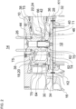
- Figures 1 and 2 show a cylinder head 10 in various sectional views.
- Figure 1 shows a cross-sectional view at the level of the valve lands of the cylinder head 10, i.e. approximately between the intermediate deck and the fire deck of the cylinder head 10, looking towards the fire deck or downwards.
- Figure 2 shows a longitudinal sectional view connecting a coolant inlet with a coolant outlet of the cylinder head 10.
- the cylinder head 10 is designed to cover a combustion chamber 12 of an internal combustion engine 14 (see Figure 2 ).
- the cylinder head 10 can be bolted to an engine block (crankcase) 16 of the internal combustion engine 14 by means of several bolts.
- the internal combustion engine 14 can preferably be incorporated into a motor vehicle, preferably a commercial vehicle, for driving the motor vehicle.
- the internal combustion engine 14 can be designed, for example, as an in-line engine or as a V-engine.
- the cylinder head 10 is designed as a single-cylinder cylinder head for covering a single combustion chamber 12 of the internal combustion engine 14. It is also possible for the cylinder head 10 to be designed as a multi-cylinder cylinder head for covering several combustion chambers of the internal combustion engine 14. Preferably, the cylinder head 10 can be cast.
- the cylinder head 10 has two inlet ports 18, 20 and two exhaust ports 22, 24. Combustion air can be supplied to the combustion chamber 12 via the two inlet ports 18. Exhaust gas can be discharged from the combustion chamber 12 via the two exhaust ports 22, 24.
- the ports 18, 20, 22, 24 each have an opening on a combustion chamber side of the cylinder head 10.
- the openings can each be closed by a valve (not shown).
- the valves are preferably designed as poppet valves.
- the openings can each have a valve seat for the respective valve.
- Valve seat inserts can be inserted into the valve seats. To open the valves, these can lift off from the respective valve seats (or valve seat inserts). To close the valves, these can make sealing contact with the respective valve seat (or valve seat insert).
- the valves can be actuated, for example, via a mechanical valve train.
- the cylinder head 10 has a receptacle 26.
- the receptacle 26 can be arranged centrally in the cylinder head 10.
- the receptacle 26 can have an opening on the combustion chamber side.
- the opening of the receptacle 26 can preferably be arranged centrally between the openings of the channels 18, 20, 22, 24.
- the receptacle 26 can be configured to accommodate a desired component (not shown).
- the receptacle 26 can be configured to accommodate a fuel injector or a spark plug.
- the cylinder head 10 has a coolant jacket 36, 38, preferably a water jacket, for heat dissipation.
- the coolant jacket 36, 38 can be cast directly with the cylinder head 10.
- the coolant jacket 36, 38 is formed from a plurality of coolant chambers and coolant channels that are in fluid communication with one another.
- the coolant jacket 36, 38 has a, preferably single, coolant inlet 28 and a, preferably single, coolant outlet 30 (see Figure 2 ). Coolant can be supplied to the coolant jacket 36, 38 via the coolant inlet 28. (Heated) coolant can be discharged from the coolant jacket 36, 38 via the coolant outlet 30.
- the coolant inlet 28 and the coolant outlet 30 are fluidly connected to one another via the plurality of coolant chambers and coolant channels of the coolant jacket 36, 38.
- the coolant inlet 28 and the coolant outlet 30 are preferably arranged on opposite sides of the cylinder head 10.
- the coolant inlet 28 is connected to a coolant supply channel 32 of the engine block 16.
- the coolant supply channel 32 serves as a coolant source or pressure source.
- the coolant supply channel 32 can be designed, for example, as a coolant distribution bar.
- the coolant supply channel 32 can be supplied with coolant, preferably cooling water, by means of a coolant pump.
- the coolant outlet 30 is connected to a coolant discharge channel 34 of the engine block 16.
- the coolant discharge channel 34 serves as a pressure sink.
- the coolant discharge channel 34 can be designed, for example, as a collecting channel. Different arrangements for the coolant inlet 28 and/or the coolant outlet 30 are also possible.
- the coolant jacket 36, 38 can be divided into a lower coolant jacket 36 and an upper coolant jacket 38.
- the lower coolant jacket 36 is arranged between a fire deck 40 and an intermediate deck 42 of the cylinder head 10.
- the upper coolant jacket 38 is arranged between the intermediate deck 42 and an upper deck 44 of the cylinder head 10.
- the coolant inlet 28 opens into the lower coolant jacket 36.
- the lower coolant jacket 36 opens into the coolant outlet 30.
- the lower coolant jacket 36 has four, preferably cast, coolant channels 46, 48, 50, 52.
- the four coolant channels 46, 48, 50, 52 are arranged substantially between the fire deck 40 and the intermediate deck 42.
- the first coolant channel 46 is arranged in a valve land region 54 between the two outlet channels 22, 24.
- the second coolant channel 48 is arranged in a valve land region 56 between the second outlet channel 24 and the first inlet channel 18.
- the third coolant channel 50 is arranged in a valve land region 58 between the second inlet channel 20 and the first outlet channel 22.
- the fourth coolant channel 52 is arranged in a valve land region 60 between the first inlet channel 18 and the second inlet channel 20.
- Coolant can flow through the coolant channels 46, 48, 50 in a radially inward direction relative to a central axis of the cylinder head 10. Coolant can flow through the fourth coolant channel 52 in a radially outward direction relative to the central axis.
- the coolant channels 46, 48, 50 are arranged downstream of the coolant inlet 28.
- the fourth coolant channel 52 is arranged downstream of the coolant channels 46, 48, 50.
- Coolant flowing through the first coolant channel 46 cools, in particular, the fire deck 40, the two outlet channels 22, 24 and their valve seats.
- Coolant flowing through the third coolant channel 50 cools in particular the fire deck 40, the second outlet channel 24, the first inlet channel 18 and the valve seats of the channels 18, 24.
- Coolant flowing through the third coolant channel 50 cools in particular the fire deck 40, the second inlet channel 20, the first outlet channel 22 and the valve seats of the channels 20, 22.
- Coolant flowing through the fourth coolant channel cools in particular the fire deck 40, the two inlet channels 18, 20 and their valve seats.
- the upper coolant jacket 38 can be annular.
- the upper coolant jacket 38 can surround the receptacle 26 coaxially and at a distance from it. Coolant flowing through the upper coolant jacket 38 cools, in particular, the channels 18, 20, 22, 24 and the valve guides for the valves of the channels 18, 20, 22, 24.
- the lower coolant jacket 36 and the upper coolant jacket 38 are (e.g. only) in fluid communication with each other via a coolant chamber 62 and a transfer 64.
- the coolant chamber 62 is arranged downstream of the channels 20, 22, 24.
- the coolant chamber 62 is arranged upstream of the upper coolant jacket 38.
- the coolant chamber 62 can preferably be annular and coaxially surround the receptacle 26. Coolant flowing through the coolant chamber 62 can, for example, directly flow around and thereby cool a mounting sleeve 66 (for example, for a fuel injector or a spark plug) that is received in the receptacle 26.
- the mounting sleeve 66 can be arranged in a sealed manner in the receptacle 26.
- the coolant chamber 62 is flowed through from below by the lower coolant jacket 36 upwards to the upper coolant jacket 38.
- the overflow 64 is arranged downstream of the upper coolant jacket 38.
- the overflow 64 is preferably arranged on the side of the cylinder head 10 on which the coolant outlet 30 is arranged. This is preferably the side of the cylinder head 10 opposite the side of the cylinder head on which the coolant inlet 28 is arranged.
- the overflow 64 is traversed from above by the upper coolant jacket 38 downwards to the lower coolant jacket 36.
- the coolant is supplied via the coolant supply channel 32.
- the coolant flows from the coolant supply channel 32 in a coolant flow (e.g., total coolant flow) K1 (see arrow in Figures 1 and 2 ) into the coolant inlet 28.
- a coolant flow e.g., total coolant flow
- K1 total coolant flow
- the coolant flow K1 splits directly into three coolant sub-flows T1, T2 and T3.
- the first coolant partial flow T1 flows through the first coolant channel 46 and cools the surrounding areas.
- the second coolant partial flow T2 flows through the second coolant channel 48 and also cools the surrounding areas.
- the third coolant partial flow T3 flows through the third coolant channel 50 and also cools the surrounding areas. Consequently, the freshly supplied coolant initially cools the valve land areas 54, 56 and 58, which are subject to high thermal loads.
- the valve land area 54 is arranged between the two exhaust channels 22, 24, which carry hot exhaust gas during operation of the internal combustion engine 14. The valve land area 54 can therefore be subject to particularly high thermal loads.
- the two valve land areas 56 and 58 also each border one of the two exhaust channels 22, 24 and are therefore also subject to high thermal loads.
- the coolant channels 46, 48, and 50 are dimensioned and arranged relative to one another such that, taking into account the pressure losses that occur, the first coolant partial flow T1, which flows through the valve land region 54 subject to the highest thermal load, is the largest in order to achieve the greatest cooling effect.
- the first coolant partial flow T1 can be in a range between 40% and 60%, preferably around 50%, of the incoming coolant flow K1, for example based on a mass flow of the coolant.
- the second coolant partial flow and the third coolant partial flow T3 can each be in a range between 15% and 35%, preferably around 25%, of the incoming coolant flow K1, for example based on a mass flow of the coolant.
- the coolant partial flows T1, T2, and T3 can reunite in a central region of the lower coolant jacket 36.
- the central region can, for example, be designed as an annular space surrounding the receptacle 26.
- the coolant flow thus combined (e.g., total coolant flow) can in turn be divided into two coolant partial flows T4 and T5.
- the fourth coolant partial flow T4 flows through the fourth coolant channel 52, thereby cooling the surrounding areas.
- the valve land area 60 surrounding the fourth coolant channel 52 is subject to less thermal stress than the valve land areas 54, 56, 58, since the valve land area 60 only borders the two inlet channels 18, 20, which supply relatively cool combustion air to the combustion chamber 12 during operation.
- the fifth coolant partial flow T5 flows upward from the central region of the lower coolant jacket 36 through the coolant chamber 62 into the upper coolant jacket 38.
- the component arranged in the receptacle 26 can be directly or indirectly surrounded by coolant and thereby cooled.
- the mounting sleeve 66 can be directly surrounded by coolant in order to effectively cool the component arranged in the mounting sleeve 66, for example, the fuel injector or spark plug.
- the still comparatively cool coolant partial flow T5 can be used to effectively cool, for example, the thermally highly stressed fuel injector.
- the fifth coolant partial flow T5 After flowing through the coolant chamber 62, the fifth coolant partial flow T5 reaches the upper coolant jacket 38 and cools the surrounding areas. The fifth coolant partial flow T5 ultimately flows through the overflow 64 from the upper coolant jacket 38 back into the lower coolant jacket 36. There, the fourth coolant partial flow T4 and the fifth coolant partial flow T5 merge. The thus combined coolant flow (e.g., total coolant flow) K2 leaves the cylinder head 10 through the coolant outlet 30 into the coolant discharge channel 34 of the engine block 16.
- the coolant flow (e.g., total coolant flow) K2 leaves the cylinder head 10 through the coolant outlet 30 into the coolant discharge channel 34 of the engine block 16.
- the cooling requirement to be covered by the fifth coolant partial flow T5 with regard to the mounting sleeve 66 and the upper coolant jacket 38 can be greater than the cooling requirement to be covered by the fourth coolant partial flow T4 with regard to the valve web area 60. Therefore, the coolant chamber 62, the upper coolant jacket 38 and the fourth coolant channel 52 can preferably be dimensioned and arranged relative to one another such that, taking into account the pressure losses that occur, the fifth coolant partial flow T5 is greater than or at least the same size as the fourth coolant partial flow T4.
- the fifth coolant partial flow T5 can be in a range between 50% and 75% of the previously combined coolant flow from the coolant partial flows T1, T2 and T3, e.g.
- the fourth coolant partial flow T4 can be in a range between 25% and 50% of the combined coolant flow from the coolant partial flows T1, T2 and T3, e.g. B. related to a mass flow of the coolant.
- the invention is not limited to the preferred embodiments described above. Rather, a multitude of variants and modifications are possible, which also make use of the inventive concept and therefore fall within the scope of protection.
- the invention also claims protection for the subject matter and the features of the subclaims, independent of the claims referred to.
- the individual features of independent claim 1 are each independent of one another. disclosed.
- the features of the subclaims are also disclosed independently of all features of independent claim 1 and, for example, independently of the features relating to the presence and/or configuration of the first and second outlet channels, the first and second inlet channels, the receptacle, the coolant inlet, the first coolant channel, the second coolant channel, the third coolant channel and/or the coolant chamber of independent claim 1. All range specifications herein are to be understood as disclosed in such a way that, as it were, all values falling within the respective range are individually disclosed, e.g. also as respectively preferred narrower outer limits of the respective range.
Landscapes
- Engineering & Computer Science (AREA)
- Chemical & Material Sciences (AREA)
- Combustion & Propulsion (AREA)
- Mechanical Engineering (AREA)
- General Engineering & Computer Science (AREA)
- Cylinder Crankcases Of Internal Combustion Engines (AREA)
Description
- Die Erfindung betrifft einen Zylinderkopf zum Abdecken einer Verbrennungskammer einer Brennkraftmaschine und ein Verfahren zum Kühlen eines Zylinderkopfes.
- Zum Stand der Technik wird zunächst auf das Dokument
AT 6 654 U1 - Zylinderköpfe von Brennkraftmaschinen können zur Kühlung beispielsweise einen Wassermantel aufweisen. Je nach Anordnung und Ausführung kann der Wassermantel thermisch hochbelastete Bereiche des Zylinderkopfes kühlen.
- Insbesondere die Ventilstegbereiche, die zwischen den einzelnen Gasführungskanälen des Zylinderkopfes und zwischen dem Feuerdeck und dem Zwischendeck des Zylinderkopfes angeordnet sind, können eine besonders wirksame Kühlung erfordern. Einerseits kann so das Feuerdeck mit der Brennraumseite des Zylinderkopfes gekühlt werden. Andererseits können so die Ventilsitze an der Brennraumseite für die in den Gasführungskanälen angeordneten Ventile gekühlt werden. Außerdem kann beispielsweise ein Kraftstoffinjektor oder eine Zündkerze einen vergleichsweise großen Kühlbedarf haben.
- Die
DE 38 02 886 A1 offenbart einen Zylinderkopf für wassergekühlte Brennkraftmaschinen mit einem Wassermantel, einer zentralen Aufnahmebohrung für eine Einspritzdüse oder Zündkerze, mehreren Ventilen sowie Bohrungen im Bereich des Wassermantels, über die den Stegen zwischen den Ventilen Kühlwasser zugeleitet wird. - Die
DE 44 20 130 C1 offenbart einen Zylinderkopf mit vier Ventilen und mittig angeordnetem Einspritzventil für eine Brennkraftmaschine. Kühlmittelbohrungen verlaufen in unmittelbarer Nähe zu Ein- und Auslasskanälen von einem Umfang des Zylinderkopfes zu einem innenliegenden Wasserraum des Zylinderkopfes. - Der Erfindung liegt die Aufgabe zu Grunde, eine alternative und/oder verbesserte Technik zum Kühlen eines Zylinderkopfes zu schaffen.
- Die Aufgabe wird gelöst durch die Merkmale der unabhängigen Ansprüche. Vorteilhafte Weiterbildungen sind in den abhängigen Ansprüchen und der Beschreibung angegeben.
- Die Erfindung schafft einen Zylinderkopf zum Abdecken einer Verbrennungskammer einer Brennkraftmaschine. Der Zylinderkopf weist einen ersten und zweiten Auslasskanal zum Abführen von Abgas aus der Verbrennungskammer und einen ersten und zweiten Einlasskanal zum Zuführen von Verbrennungsluft zu der Verbrennungskammer auf. Der Zylinderkopf weist eine (z. B. zentrale) Aufnahme für eine Montagehülse, einen Kraftstoffinjektor oder eine Zündkerze auf. Der Zylinderkopf weist einen, vorzugsweise einzigen, (z. B. zylinderkopfbodenseitigen) Kühlmitteleintritt zum Verbinden mit einer Kühlmittelquelle auf. Der Zylinderkopf weist einen ersten Kühlmittelkanal, der (z. B. in einem Ventilstegbereich) zwischen dem ersten und zweiten Auslasskanal angeordnet ist, einen zweiten Kühlmittelkanal, der (z. B. in einem Ventilstegbereich) zwischen dem zweiten Auslasskanal und dem ersten Einlasskanal angeordnet ist, und einen dritten Kühlmittelkanal, der (z. B. in einem Ventilstegbereich) zwischen dem ersten Auslasskanal und dem zweiten Einlasskanal angeordnet ist, auf. Der erste, zweite und dritte Kühlmittelkanal sind (z. B. direkt) stromabwärts von dem Kühlmitteleintritt angeordnet und mit Kühlmittel von dem Kühlmitteleintritt parallel durchströmbar. Der Zylinderkopf weist einen Kühlmittelraum auf, der zum Kühlen der Aufnahme ausgebildet und stromabwärts von dem ersten, zweiten und dritten Kühlmittelkanal angeordnet ist. Der Zylinderkopf weist einen oberen Kühlmittelmantel, der stromabwärts von dem Kühlmittelraum angeordnet ist, auf.
- Der Zylinderkopf ermöglicht, dass das einströmende Kühlmittel zunächst die thermisch besonders hochbeanspruchten Ventilstegbereiche zwischen den Auslasskanälen und zwischen je einem Auslasskanal und einem Einlasskanal kühlt. Unmittelbar darauf kann direkt der Kraftstoffinjektor oder die Zündkerze gekühlt werden, die ebenfalls einen großen Kühlbedarf aufweisen. Die Kühlung des Kraftstoffinjektors oder der Zündkerze erfolgt, während das Kühlmittel nach oben in den oberen Kühlmittelmantel strömt, um dort beispielsweise die Ventilführungen zu kühlen.
- Beispielsweise kann als Kühlmittel Kühlwasser verwendet werden.
- In einem Ausführungsbeispiel sind der erste, zweite und dritte Kühlmittelkanal und der Kühlmitteleintritt so miteinander in Fluidverbindung, dass sich ein durch den Kühlmitteleintritt eintretender Kühlmittelstrom in (z. B. genau) drei Kühlmittelteilströme aufteilt, wobei vorzugsweise ein erster Kühlmittelteilstrom den ersten Kühlmittelkanal durchströmt, ein zweiter Kühlmittelteilstrom den zweiten Kühlmittelkanal durchströmt und/oder ein dritter Kühlmittelteilstrom den dritten Kühlmittelkanal durchströmt.
- In einer Weiterbildung sind der erste, zweite und/oder dritte Kühlmittelkanal so ausgebildet, dass der erste Kühlmittelteilstrom größer als der zweite Kühlmittelteilstrom und/oder größer als der dritte Kühlmittelteilstrom ist. Es ist möglich, dass der zweite Kühlmittelteilstrom und der dritte Kühlmittelteilstrom im Wesentlichen gleich groß sind. Es ist auch möglich, dass der erste Kühlmittelteilstrom in einem Bereich zwischen 40 % und 60 %, vorzugsweise rund 50 %, des eintretenden Kühlmittelstroms ist. Es ist ebenfalls möglich, dass der zweite Kühlmittelteilstrom in einem Bereich zwischen 15 % und 35 %, vorzugsweise rund 25 %, des eintretenden Kühlmittelstroms ist, und/oder der dritte Kühlmittelteilstrom in einem Bereich zwischen 15 % und 35 %, vorzugsweise rund 25 %, des eintretenden Kühlmittelstroms ist. Damit kann beispielsweise sichergestellt werden, dass der thermisch am höchsten belastete Ventilstegbereich zwischen den beiden Auslasskanälen am stärksten gekühlt wird.
- In einem weiteren Ausführungsbeispiel sind der erste, zweite und/oder dritte Kühlmittelkanal und der Kühlmittelraum so miteinander in Fluidverbindung, dass zumindest ein Teil eines vereinigten Kühlmittelstroms von dem ersten, zweiten und/oder dritten Kühlmittelkanal den Kühlmittelraum durchströmt.
- In einem weiteren Ausführungsbeispiel ist der Kühlmittelraum so angeordnet, dass in dem Kühlmittelraum strömendes Kühlmittel die Aufnahme, eine in der Aufnahme aufgenommene Montagehülse (z. B. für einen Kraftstoffinjektor oder eine Zündkerze), einen in der Aufnahme aufgenommenen Kraftstoffinjektor oder eine in der Aufnahme aufgenommene Zündkerze, umspült, vorzugsweise direkt. So kann die in der Aufnahme aufgenommene Komponente ebenfalls wirksam gekühlt werden.
- In einer Ausführungsform ist der Kühlmittelraum ringförmig und/oder umgibt die Aufnahme koaxial.
- In einer weiteren Ausführungsform ist der oberen Kühlmittelmantel zwischen einem Zwischendeck und einem Oberdeck des Zylinderkopfes angeordnet. Es ist möglich, dass der obere Kühlmittelmantel ringförmig ist, und/oder der obere Kühlmittelmantel zum Kühlen von Ventilführungen des Zylinderkopfes ausgebildet ist.
- In einer weiteren Ausführungsform sind der Kühlmittelraum und der obere Kühlmittelmantel so miteinander in Fluidverbindung, dass Kühlmittel von dem ersten, zweiten und dritten Kühlmittelkanal zumindest teilweise nach oben durch den Kühlmittelraum zu dem oberen Kühlmittelmantel strömt.
- Der Zylinderkopf weist einen vierten Kühlmittelkanal auf, der zwischen dem ersten Einlasskanal und dem zweiten Einlasskanal und (z. B. direkt) stromabwärts von dem ersten, zweiten und dritten Kühlmittelkanal angeordnet ist. Somit kann auch dieser
- Ventilstegbereich wirksam gekühlt werden. Vorzugsweise kann der vierte Kühlmittelkanal zwischen einem Feuerdeck und einem Zwischendeck des Zylinderkopfes angeordnet sein. Beispielsweise kann der vierte Kühlmittelkanal zum Kühlen eines Feuerdecks des Zylinderkopfes, des ersten und zweiten Einlasskanals und/oder von Ventilsitzen des ersten und des zweiten Einlasskanals angeordnet sein.
- In einer Weiterbildung sind der Kühlmittelraum und der vierte Kühlmittelkanal so in Fluidverbindung mit dem ersten, zweiten und dritten Kühlmittelkanal, dass ein vereinigter Kühlmittelstrom von dem ersten, zweiten und dritten Kühlmittelkanal (z. B. nur) in einen vierten Kühlmittelteilstrom durch den vierten Kühlmittelkanal und in einen fünften Kühlmittelteilstrom durch den Kühlmittelraum aufgeteilt wird.
- In einer Weiterbildung sind der vierte Kühlmittelkanal und der Kühlmittelraum so ausgebildet, dass der fünfte Kühlmittelteilstrom größer als oder im Westlichen gleich groß wie der vierte Kühlmittelteilstrom ist. Es ist möglich, dass der fünfte Kühlmittelteilstrom in einem Bereich zwischen 50 % und 75 % des vereinigten Kühlmittelstroms ist, und/oder der vierte Kühlmittelteilstrom in einem Bereich zwischen 25 % und 50 % des vereinigten Kühlmittelstroms ist. Damit kann sichergestellt werden, dass die von dem Kraftstoffinjektor oder der Zündkerze sowie den Ventilführungen benötigte Kühlung von dem fünften Kühlmittelteilstrom bereitgestellt werden kann.
- Der Zylinderkopf weist ferner einen, vorzugsweise einzigen, (z. B. zylinderkopfbodenseitigen) Kühlmittelaustritt auf, der (z. B. direkt) stromabwärts von dem oberen Kühlmittelmantel und dem vierten Kühlmittelkanal angeordnet ist.
- Ein Übertritt von dem oberen Kühlmittelmantel zu dem Kühlmittelaustritt ist auf der gleichen Seite des Zylinderkopfes angeordnet wie der Kühlmittelaustritt. Es ist möglich, dass ein Übertritt von dem oberen Kühlmittelmantel und der vierte Kühlmittelkanal sich angrenzend an oder neben dem Kühlmittelaustritt vereinigen. Alternativ oder zusätzlich ist der Übertritt auf einer dem Kühlmitteleintritt entgegengesetzten Seite des Zylinderkopfes angeordnet. Damit kann ein möglichst geringer Druckverlust bewirkt werden, sodass der gewünschte Massenstrom für den fünften Kühlmittelteilstrom erreichbar ist.
- In einer weiteren Ausführungsvariante ist der Kühlmittelaustritt so in Fluidverbindung mit dem oberen Kühlmittelmantel und dem vierten Kühlmittelkanal, dass sich der fünfte Kühlmittelteilstrom von dem oberen Kühlmittelmantel und der vierte Kühlmittelteilstrom von dem vierten Kühlmittelkanal vereinigen und zum Kühlmittelaustritt strömen.
- In einem Ausführungsbeispiel ist der erste Kühlmittelkanal zum Kühlen eines Feuerdecks des Zylinderkopfes, des ersten und zweiten Auslasskanals und/oder von Ventilsitzen des ersten und zweiten Auslasskanals angeordnet. Alternativ oder zusätzlich ist der zweite Kühlmittelkanal zum Kühlen eines Feuerdecks des Zylinderkopfes, des zweiten Auslasskanals, des ersten Einlasskanals und/oder von Ventilsitzen des zweiten Auslasskanals und des ersten Einlasskanals angeordnet. Alternativ oder zusätzlich ist der dritte Kühlmittelkanal zum Kühlen eines Feuerdecks des Zylinderkopfes, des ersten Auslasskanals, des zweiten Einlasskanals und/oder von Ventilsitzen des ersten Auslasskanals und des zweiten Einlasskanals angeordnet.
- In einem weiteren Ausführungsbeispiel ist der erste, zweite und/oder dritte Kühlmittelkanal zwischen einem Feuerdeck und einem Zwischendeck des Zylinderkopfes angeordnet.
- In einer Ausführungsform weist ein unterer Kühlmittelmantel des Zylinderkopfes den ersten, zweiten, dritten und/oder vierten Kühlmittelkanal auf.
- In einer weiteren Ausführungsform ist der Kühlmittelraum zwischen einem unteren Kühlmittelmantel des Zylinderkopfes und dem oberen Kühlmittelmantel angeordnet
Es ist möglich, dass der untere Kühlmittelmantel zwischen einem Feuerdeck und einem Zwischendeck des Zylinderkopfes angeordnet ist. - Es ist möglich, dass der obere Kühlmittelmantel zwischen einem Zwischendeck und einem Oberdeck des Zylinderkopfes angeordnet ist.
- Vorzugsweise kann der erste Kühlmittelkanal, der zweite Kühlmittelkanal, der dritte Kühlmittelkanal, der vierte Kühlmittelkanal, der Kühlmitteleintritt, der Kühlmittelaustritt der Kühlmittelraum, der obere Kühlmittelmantel, der untere Kühlmittelmantel und/oder der Übertritt gegossen sein.
- Es ist möglich, dass der erste, zweite und/oder dritte Kühlmittelkanal bezüglich einer Mittelachse des Zylinderkopfes in einer Radialrichtung nach innen mit Kühlmittel durchströmt werden und/oder der vierte Kühlmittelkanal bezüglich der Mittelachse in einer Radialrichtung nach außen durchströmt wird.
- Es ist möglich, dass der Kühlmittelraum koaxial zu einer Mittelachse des Zylinderkopfes angeordnet ist.
- Die Erfindung betrifft auch ein Kraftfahrzeug, vorzugsweise ein Nutzfahrzeug (z. B. Lastkraftwagen oder Omnibus), mit einem Zylinderkopf wie hierin offenbart.
- Es ist auch möglich, den Zylinderkopf wie hierin offenbart für Personenkraftwagen, Großmotoren, geländegängige Fahrzeuge, stationäre Motoren, Marinemotoren usw. zu verwenden.
- Die Erfindung betrifft auch ein Verfahren zum Kühlen eines Zylinderkopfes wie hierin offenbart. Das Verfahren weist ein Zuführen eines Kühlmittelstroms zu dem Zylinderkopf auf (z. B. mittels eines Kühlmitteleintritts). Das Verfahren weist ein Aufteilen des Kühlmittelstroms in einen ersten Kühlmittelteilstrom, einen zweiten Kühlmitteteilstrom und einen dritten Kühlmittelteilstrom auf. Das Verfahren weist ein Kühlen eines Bereichs zwischen einem ersten Auslasskanal und einem zweiten Auslasskanal des Zylinderkopfes mittels des ersten Kühlmittelteilstroms auf (z. B. mittels eines ersten Kühlmittelkanals). Das Verfahren weist ein Kühlen eines Bereichs zwischen dem zweiten Auslasskanal und einem ersten Einlasskanal des Zylinderkopfes mittels des zweiten Kühlmittelteilstroms auf (z. B. mittels eines zweiten Kühlmittelkanals). Das Verfahren weist ein Kühlen eines Bereichs zwischen dem ersten Auslasskanal und einem zweiten Einlasskanal des Zylinderkopfes mittels des dritten Kühlmittelteilstroms auf (z. B. mittels eines dritten Kühlmittelkanals). Das Verfahren weist ein Vereinigen des ersten, zweiten und dritten Kühlmittelteilstroms auf. Das Verfahren weist ein Aufteilen des vereinigten Kühlmittelstroms in einen vierten Kühlmittelteilstrom und einen fünften Kühlmittelteilstrom auf. Das Verfahren weist ein Kühlen eines Bereichs um eine Montagehülse, einen Kraftstoffinjektor oder eine Zündkerze mittels des fünften Kühlmittelteilstroms (z. B. mittels eines Kühlmittelraums) und danach Kühlen eines oberen Kühlmittelmantels und/oder von Ventilführungen für Ventile des Zylinderkopfes mittels des fünften Kühlmittelteilstroms auf. Vorzugsweise weist das Verfahren noch ein Kühlen eines Bereichs zwischen dem ersten Einlasskanal und dem zweiten Einlasskanal mittels des vierten Kühlmittelteilstroms auf (z. B. mittels eines vierten Kühlmittelkanals). Das Verfahren ermöglicht die Erzielung der gleichen Vorteile wie bereits für den Zylinderkopf beschrieben wurde.
- Vorzugsweise kann das Verfahren ferner ein Vereinigen des vierten Kühlmittelteilstroms und des fünften Kühlmittelteilstroms aufweisen, zum Beispiel nach dem Kühlen des Bereichs zwischen dem ersten Einlasskanal und dem zweiten Einlasskanal mittels des vierten Kühlmittelteilstroms und/oder nach dem Kühlen des oberen Kühlmittelmantels und/oder der Ventilführungen mittels des fünften Kühlmittelteilstroms.
- Beispielsweise kann das Verfahren ferner ein Abführen des vereinigten Kühlmittelstroms aus dem Zylinderkopf aufweisen (z. B. mittels eines Kühlmittelaustritts).
- Die zuvor beschriebenen bevorzugten Ausführungsformen und Merkmale der Erfindung sind beliebig miteinander kombinierbar. Weitere Einzelheiten und Vorteile der Erfindung werden im Folgenden unter Bezug auf die beigefügten Zeichnungen beschrieben. Es zeigen:
- Figur 1
- eine Querschnittansicht eines Zylinderkopfes gemäß einem Ausführungsbeispiel der vorliegenden Offenbarung; und
- Figur 2
- eine Längsschnittansicht durch den beispielhaften Zylinderkopf.
- Die in den Figuren gezeigten Ausführungsformen stimmen zumindest teilweise überein, so dass ähnliche oder identische Teile mit den gleichen Bezugszeichen versehen sind und zu deren Erläuterung auch auf die Beschreibung der anderen Ausführungsformen bzw. Figuren verwiesen wird, um Wiederholungen zu vermeiden.
- Die
Figuren 1 und2 zeigen einen Zylinderkopf 10 in verschiedenen Schnittansichten. Die Figur 1 zeigt eine Querschnittansicht auf Höhe der Ventilstege des Zylinderkopfes 10, also ungefähr zwischen dem Zwischendeck und dem Feuerdeck des Zylinderkopfes 10, mit Blickrichtung zum Feuerdeck bzw. nach unten. DieFigur 2 zeigt eine Längsschnittansicht, die einen Kühlmitteleintritt mit einem Kühlmittelaustritt des Zylinderkopfes 10 verbindet. - Der Zylinderkopf 10 ist zum Abdecken einer Verbrennungskammer 12 einer Brennkraftmaschine 14 ausgebildet (siehe
Figur 2 ). Beispielsweise kann der Zylinderkopf 10 mittels mehrerer Bolzen mit einem Motorblock (Kurbelgehäuse) 16 der Brennkraftmaschine 14 verschraubt werden. Vorzugsweise kann die Brennkraftmaschine 14 in einem Kraftfahrzeug, vorzugsweise einem Nutzfahrzeug, zum Antreiben des Kraftfahrzeugs umfasst sein. Die Brennkraftmaschine 14 kann beispielsweise als Reihenmotor oder als V-Motor ausgeführt sein. - Der Zylinderkopf 10 ist als ein Einzylinder-Zylinderkopf zum Abdecken einer einzigen Verbrennungskammer 12 der Brennkraftmaschine 14 ausgeführt. Es ist auch möglich, dass der Zylinderkopf 10 als ein Mehrzylinder-Zylinderkopf zum Abdecken mehrerer Verbrennungskammern der Brennkraftmaschine 14 ausgeführt ist. Vorzugsweise kann der Zylinderkopf 10 gegossen sein.
- Der Zylinderkopf 10 weist zwei Einlasskanäle 18, 20 und zwei Auslasskanäle 22, 24 auf. Mittels der zwei Einlasskanäle 18 kann Verbrennungsluft zu der Verbrennungskammer 12 zugeführt werden. Mittels der zwei Auslasskanäle 22, 24 kann Abgas aus der Verbrennungskammer 12 abgeführt werden. Die Kanäle 18, 20, 22, 24 weisen an einer Brennraumseite des Zylinderkopfes 10 jeweils eine Öffnung auf. Die Öffnungen sind jeweils durch ein Ventil (nicht dargestellt) verschließbar. Die Ventile sind vorzugsweise als Tellerventile ausgeführt. Die Öffnungen können jeweils einen Ventilsitz für das jeweilige Ventil aufweisen. In den Ventilsitzen können Ventilsitzringe eingesetzt sein. Zum Öffnen der Ventile können diese von den jeweiligen Ventilsitzen (bzw. Ventilsitzringen) abheben. Zum Schließen der Ventile können diese den jeweiligen Ventilsitz (bzw. Ventilsitzring) abdichtend kontaktieren. Die Ventile können beispielsweise über einen mechanischen Ventiltrieb betätigt werden.
- Der Zylinderkopf 10 weist eine Aufnahme 26 auf. Die Aufnahme 26 kann zentral im Zylinderkopf 10 angeordnet sein. Die Aufnahme 26 kann eine brennraumseitige Öffnung aufweisen. Die Öffnung der Aufnahme 26 kann vorzugsweise zentral zwischen den Öffnungen der Kanäle 18, 20, 22, 24 angeordnet sein. Die Aufnahme 26 kann dazu ausgebildet sein, eine gewünschte Komponente (nicht dargestellt) aufzunehmen. Beispielsweise kann die Aufnahme 26 zur Aufnahme eines Kraftstoffinjektors oder einer Zündkerze ausgebildet sein.
- Der Zylinderkopf 10 weist einen Kühlmittelmantel 36, 38, vorzugsweise einen Wassermantel, zum Abführen von Wärme auf. Der Kühlmittelmantel 36, 38 kann direkt mit dem Zylinderkopf 10 gegossen sein. Der Kühlmittelmantel 36, 38 ist aus mehreren Kühlmittelräumen und Kühlmittelkanälen, die miteinander in Fluidverbindung stehen, gebildet.
- Der Kühlmittelmantel 36, 38 weist einen, vorzugsweisen einzigen, Kühlmitteleintritt 28 und einen, vorzugsweisen einzigen, Kühlmittelaustritt 30 auf (siehe
Figur 2 ). Über den Kühlmitteleintritt 28 kann Kühlmittel zu dem Kühlmittelmantel 36, 38 zugeführt werden. Über den Kühlmittelaustritt 30 kann (erwärmtes) Kühlmittel aus dem Kühlmittelmantel 36, 38 abgeführt werden. Der Kühlmitteleintritt 28 und der Kühlmittelaustritt 30 sind über die mehreren Kühlmittelräume und Kühlmittelkanäle des Kühlmittelmantels 36, 38 miteinander in Fluidverbindung. Der Kühlmitteleintritt 28 und der Kühlmittelaustritt 30 sind vorzugsweise auf entgegengesetzten Seiten des Zylinderkopfes 10 angeordnet. - Im dargestellten Ausführungsbeispiel ist der Kühlmitteleintritt 28 mit einem Kühlmittelzufuhrkanal 32 des Motorblocks 16 verbunden. Der Kühlmittelzufuhrkanal 32 dient als Kühlmittelquelle bzw. Druckquelle. Der Kühlmittelzufuhrkanal 32 kann beispielsweise als eine Kühlmittelverteilerleiste ausgeführt sein. Der Kühlmittelzufuhrkanal 32 kann mittels einer Kühlmittelpumpe mit Kühlmittel, vorzugsweise Kühlwasser, versorgt werden. Der Kühlmittelaustritt 30 ist mit einem Kühlmittelabführkanal 34 des Motorblocks 16 verbunden. Der Kühlmittelabführkanal 34 dient als eine Drucksenke. Der Kühlmittelabführkanal 34 kann beispielsweise als ein Sammelkanal ausgeführt sein. Davon abweichende Anordnungen für den Kühlmitteleintritt 28 und/oder den Kühlmittelaustritt 30 sind ebenfalls möglich.
- Der Kühlmittelmantel 36, 38 kann in einen unteren Kühlmittelmantel 36 und einen oberen Kühlmittelmantel 38 unterteilt sein. Der untere Kühlmittelmantel 36 ist zwischen einem Feuerdeck 40 und einem Zwischendeck 42 des Zylinderkopfes 10 angeordnet. Der obere Kühlmittelmantel 38 ist zwischen dem Zwischendeck 42 und einem Oberdeck 44 des Zylinderkopfes 10 angeordnet. Der Kühlmitteleintritt 28 mündet in den unteren Kühlmittelmantel 36. Der untere Kühlmittelmantel 36 mündet in den Kühlmittelaustritt 30.
- Der untere Kühlmittelmantel 36 weist vier, vorzugsweise gegossene, Kühlmittelkanäle 46, 48, 50, 52 auf. Die vier Kühlmittelkanäle 46, 48, 50, 52 sind im Wesentlichen zwischen dem Feuerdeck 40 und dem Zwischendeck 42 angeordnet. Der erste Kühlmittelkanal 46 ist in einem Ventilstegbereich 54 zwischen den zwei Auslasskanälen 22, 24 angeordnet. Der zweite Kühlmittelkanal 48 ist in einem Ventilstegbereich 56 zwischen dem zweiten Auslasskanal 24 und dem ersten Einlasskanal 18 angeordnet. Der dritte Kühlmittelkanal 50 ist in einem Ventilstegbereich 58 zwischen dem zweiten Einlasskanal 20 und dem ersten Auslasskanal 22 angeordnet. Der vierte Kühlmittelkanal 52 ist in einem Ventilstegbereich 60 zwischen dem ersten Einlasskanal 18 und dem zweiten Einlasskanal 20 angeordnet.
- Die Kühlmittelkanäle 46, 48, 50 können bezüglich einer Mittelachse des Zylinderkopfes 10 in einer Richtung radial nach innen mit Kühlmittel durchströmt werden. Der vierte Kühlmittelkanal 52 kann bezüglich der Mittelachse in einer Richtung radial nach außen mit Kühlmittel durchströmt werden. Die Kühlmittelkanäle 46, 48, 50 sind stromabwärts von dem Kühlmitteleintritt 28 angeordnet. Der vierte Kühlmittelkanal 52 ist stromabwärts von den Kühlmittelkanälen 46, 48, 50 angeordnet.
- Durch den ersten Kühlmittelkanal 46 strömendes Kühlmittel kühlt insbesondere das Feuerdeck 40, die beiden Auslasskanäle 22, 24 und deren Ventilsitze. Durch den zweiten Kühlmittelkanal 48 strömendes Kühlmittel kühlt insbesondere das Feuerdeck 40, den zweiten Auslasskanal 24, den ersten Einlasskanal 18 sowie die Ventilsitze der Kanäle 18, 24. Durch den dritten Kühlmittelkanal 50 strömendes Kühlmittel kühlt insbesondere das Feuerdeck 40, den zweiten Einlasskanal 20, den ersten Auslasskanal 22 sowie die Ventilsitze der Kanäle 20, 22. Durch den vierten Kühlmittelkanal strömendes Kühlmittel kühlt insbesondere das Feuerdeck 40, die beiden Einlasskanäle 18, 20 sowie deren Ventilsitze.
- Der obere Kühlmittelmantel 38 kann ringförmig ausgeführt sein. Der obere Kühlmittelmantel 38 kann die Aufnahme 26 koaxial und beabstandet umgeben. Durch den oberen Kühlmittelmantel 38 strömendes Kühlmittel kühlt insbesondere die Kanäle 18, 20, 22, 24 und Ventilführungen für die Ventile der Kanäle 18, 20, 22, 24.
- Der untere Kühlmittelmantel 36 und der obere Kühlmittelmantel 38 sind (z. B. nur) in Fluidverbindung miteinander über einen Kühlmittelraum 62 und einen Übertritt 64.
- Der Kühlmittelraum 62 ist stromabwärts der Kanäle 20, 22, 24 angeordnet. Der Kühlmittelraum 62 ist stromaufwärts von dem oberen Kühlmittelmantel 38 angeordnet. Vorzugsweise kann der Kühlmittelraum 62 ringförmig sein und die Aufnahme 26 koaxial umgeben. Durch den Kühlmittelraum 62 strömendes Kühlmittel kann beispielsweise eine Montagehülse 66 (zum Beispiel für einen Kraftstoffinjektor oder eine Zündkerze), die in der Aufnahme 26 aufgenommen ist, direkt umspülen und dabei kühlen. Die Montagehülse 66 kann abgedichtet in der Aufnahme 26 angeordnet sein. Der Kühlmittelraum 62 wird von unten von dem unteren Kühlmittelmantel 36 nach oben zu dem oberen Kühlmittelmantel 38 durchströmt.
- Der Übertritt 64 ist stromabwärts des oberen Kühlmittelmantels 38 angeordnet. Der Übertritt 64 ist vorzugsweise auf der Seite des Zylinderkopfes 10 angeordnet, auf der der Kühlmittelaustritt 30 angeordnet ist. Bevorzugt ist dies diejenige Seite des Zylinderkopfes 10, die der Seite des Zylinderkopfes, auf der der Kühlmitteleintritt 28 angeordnet ist, entgegengesetzt ist. Der Übertritt 64 wird von oben von dem oberen Kühlmittelmantel 38 nach unten zu dem unteren Kühlmittelmantel 36 durchströmt.
- Nachfolgend ist der durch die oben beschriebene Anordnung bewirkte Kühlmittelstrom vom Kühlmitteleintritt 28 zum Kühlmittelaustritt 30 unter Bezugnahme auf die
Figuren 1 und2 beschrieben. - Das Kühlmittel wird über den Kühlmittelzufuhrkanal 32 zugeführt. Das Kühlmittel strömt von dem Kühlmittelzufuhrkanal 32 in einem Kühlmittelstrom (z. B. Kühlmittelgesamtstrom) K1 (siehe Pfeil in
Figuren 1 und2 ) in den Kühlmitteleintritt 28. Nach dem Einströmen durch den Kühlmitteleintritt 28 teilt sich der Kühlmittelstrom K1 direkt in drei Kühlmittelteilströme T1, T2 und T3 auf. - Der erste Kühlmittelteilstrom T1 durchströmt den ersten Kühlmittelkanal 46 und kühlt dabei die umliegenden Bereiche. Der zweite Kühlmittelteilstrom T2 durchströmt den zweiten Kühlmittelkanal 48 und kühlt dabei ebenfalls die umliegenden Bereiche. Der dritte Kühlmittelteilstrom T3 durchströmt den dritten Kühlmittelkanal 50 und kühlt dabei ebenfalls die umliegenden Bereiche. Folglich kühlt das frisch zugeführte Kühlmittel zunächst die Ventilstegbereiche 54, 56 und 58, die thermisch hochbelastet sind. Der Ventilstegbereich 54 ist zwischen den zwei Auslasskanälen 22, 24 angeordnet, die im Betrieb der Brennkraftmaschine 14 heißes Abgas führen. Der Ventilstegbereich 54 kann damit thermisch besonders hochbelastet sein. Auch die beiden Ventilstegbereiche 56 und 58 grenzen jeweils an einen der beiden Auslasskanäle 22, 24 an, und sind damit ebenfalls thermisch hochbelastet.
- Vorzugsweise sind die Kühlmittelkanäle 46, 48 und 50 so relativ zueinander dimensioniert und angeordnet, dass unter Berücksichtigung der auftretenden Druckverluste der erste Kühlmittelteilstrom T1, der den thermisch am höchsten belasteten Ventilstegbereich 54 durchströmt, am größten ist, um die größte Kühlwirkung zu entfalten. Beispielsweise kann der erste Kühlmittelteilstrom T1 in einem Bereich zwischen 40 % und 60 %, vorzugsweise rund 50 %, des eintretenden Kühlmittelstroms K1 sein, zum Beispiel bezogen auf einen Massenstrom des Kühlmittels. Der zweite Kühlmittelteilstrom und der dritte Kühlmittelteilstrom T3 können beispielsweise jeweils in einem Bereich zwischen 15 % und 35 %, vorzugsweise rund 25 %, des eintretenden Kühlmittelstroms K1 sein, zum Beispiel bezogen auf einen Massenstrom des Kühlmittels.
- Die Kühlmittelteilströme T1, T2 und T3 können sich in einem zentralen Bereich des unteren Kühlmittelmantels 36 wiedervereinigen. Der zentrale Bereich kann beispielsweise als ein Ringraum ausgeführt sein, der die Aufnahme 26 umgibt. Der so vereinigte Kühlmittelstrom (z. B. Kühlmittelgesamtstrom) kann wiederum in zwei Kühlmittelteilströme T4 und T5 aufgeteilt werden.
- Der vierte Kühlmittelteilstrom T4 durchströmt den vierten Kühlmittelkanal 52 und kühlt dabei die umliegenden Bereiche. Der Ventilstegbereich 60, der den vierten Kühlmittelkanal 52 umgibt, ist weniger thermisch belastet als die Ventilstegbereiche 54, 56, 58, da der Ventilstegbereich 60 nur an die beiden Einlasskanäle 18, 20 grenzt, die im Betrieb verhältnismäßig kühle Verbrennungsluft zu der Verbrennungskammer 12 zuführen.
- Der fünfte Kühlmittelteilstrom T5 strömt vom zentralen Bereich des unteren Kühlmittelmantels 36 nach oben durch den Kühlmittelraum 62 in den oberen Kühlmittelmantel 38. Beim Durchströmen des Kühlmittelraums 62 kann die in der Aufnahme 26 angeordnete Komponente mittelbar oder unmittelbar mit Kühlmittel umströmt und dabei gekühlt werden. Beispielsweise kann die Montagehülse 66 direkt umströmt werden, um damit die in der Montagehülse 66 angeordnete Komponente, zum Beispiel den Kraftstoffinjektor oder die Zündkerze, wirksam gekühlt werden. Somit kann mit dem noch immer vergleichsweise kühlen Kühlmittelteilstrom T5 beispielsweise der thermisch hochbeanspruchte Kraftstoffinjektor wirksam gekühlt werden.
- Nach dem Durchströmen des Kühlmittelraums 62 erreicht der fünfte Kühlmittelteilstrom T5 den oberen Kühlmittelmantel 38 und kühlt die umliegenden Bereiche. Der fünfte Kühlmittelteilstrom T5 strömt letztlich durch den Übertritt 64 aus dem oberen Kühlmittelmantel 38 zurück in den unteren Kühlmittelmantel 36. Dort vereinigen sich der vierte Kühlmittelteilstrom T4 und der fünfte Kühlmittelteilstrom T5 miteinander. Der so vereinigte Kühlmittelstrom (z. B. Kühlmittelgesamtstrom) K2 verlässt den Zylinderkopf 10 durch den Kühlmittelaustritt 30 in den Kühlmittelabführkanal 34 des Motorblocks 16.
- Der durch den fünften Kühlmittelteilstrom T5 zu deckende Kühlbedarf bezüglich der Montagehülse 66 und des oberen Kühlmittelmantels 38 kann größer sein als der durch den vierten Kühlmittelteilstrom T4 zu deckende Kühlbedarf bezüglich des Ventilstegbereichs 60. Vorzugsweise können daher der Kühlmittelraum 62, der obere Kühlmittelmantel 38 und der vierte Kühlmittelkanal 52 so relativ zueinander dimensioniert und angeordnet sein, dass unter Berücksichtigung der auftretenden Druckverluste der fünfte Kühlmittelteilstrom T5 größer oder zumindest gleich groß wie der vierte Kühlmittelteilstrom T4 ist. Bevorzugt kann der fünfte Kühlmittelteilstrom T5 in einem Bereich zwischen 50 % und 75 % des zuvor vereinigten Kühlmittelstroms aus den Kühlmittelteilströmen T1, T2 und T3 sein, z. B. bezogen auf einen Massenstrom des Kühlmittels. Der vierte Kühlmittelteilstrom T4 kann in einem Bereich zwischen 25 % und 50 % des vereinigten Kühlmittelstroms aus den Kühlmittelteilströmen T1, T2 und T3 sein, z. B. bezogen auf einen Massenstrom des Kühlmittels.
- Die Erfindung ist nicht auf die vorstehend beschriebenen bevorzugten Ausführungsbeispiele beschränkt. Vielmehr ist eine Vielzahl von Varianten und Abwandlungen möglich, die ebenfalls von dem Erfindungsgedanken Gebrauch machen und deshalb in den Schutzbereich fallen. Insbesondere beansprucht die Erfindung auch Schutz für den Gegenstand und die Merkmale der Unteransprüche unabhängig von den in Bezug genommenen Ansprüchen. Insbesondere sind die einzelnen Merkmale des unabhängigen Anspruchs 1 jeweils unabhängig voneinander offenbart. Zusätzlich sind auch die Merkmale der Unteransprüche unabhängig von sämtlichen Merkmalen des unabhängigen Anspruchs 1 und beispielsweise unabhängig von den Merkmalen bezüglich des Vorhandenseins und/oder der Konfiguration des ersten und zweiten Auslasskanals, des ersten und zweiten Einlasskanals, der Aufnahme, des Kühlmitteleintritts, des ersten Kühlmittelkanals, des zweiten Kühlmittelkanals, des dritten Kühlmittelkanals und/oder des Kühlmittelraums des unabhängigen Anspruchs 1 offenbart. Alle Bereichsangaben hierin sind derart offenbart zu verstehen, dass gleichsam alle in den jeweiligen Bereich fallenden Werte einzeln offenbart sind, z. B. auch als jeweils bevorzugte engere Außengrenzen des jeweiligen Bereichs.
-
- 10
- Zylinderkopf
- 12
- Verbrennungskammer
- 14
- Brennkraftmaschine
- 16
- Motorblock
- 18
- Erster Einlasskanal
- 20
- Zweiter Einlasskanal
- 22
- Erster Auslasskanal
- 24
- Zweiter Auslasskanal
- 26
- Aufnahme
- 28
- Kühlmitteleintritt
- 30
- Kühlmittelaustritt
- 32
- Kühlmittelzufuhrkanal
- 34
- Kühlmittelabführkanal
- 36
- Unterer Kühlmittelmantel
- 38
- Oberer Kühlmittelmantel
- 40
- Feuerdeck
- 42
- Zwischendeck
- 44
- Oberdeck
- 46
- Erster Kühlmittelkanal
- 48
- Zweiter Kühlmittelkanal
- 50
- Dritter Kühlmittelkanal
- 52
- Vierter Kühlmittelkanal
- 54
- Ventilstegbereich
- 56
- Ventilstegbereich
- 58
- Ventilstegbereich
- 60
- Ventilstegbereich
- 62
- Kühlmittelraum
- 64
- Übertritt
- 66
- Montagehülse
- K1, K2
- Kühlmittelstrom
- T1-T5
- Kühlmittelteilstrom
Claims (14)
- Zylinderkopf (10) zum Abdecken einer Verbrennungskammer (12) einer Brennkraftmaschine (14), aufweisend:einen ersten und zweiten Auslasskanal (22, 24) zum Abführen von Abgas aus der Verbrennungskammer (12);einen ersten und zweiten Einlasskanal (18, 20) zum Zuführen von Verbrennungsluft zu der Verbrennungskammer (12);eine Aufnahme (26) für eine Montagehülse (66), einen Kraftstoffinjektor oder eine Zündkerze;einen, vorzugsweise einzigen, Kühlmitteleintritt (28) zum Verbinden mit einer Kühlmittelquelle,einen ersten Kühlmittelkanal (46), der zwischen dem ersten und zweiten Auslasskanal (22, 24) angeordnet ist;einen zweiten Kühlmittelkanal (48), der zwischen dem zweiten Auslasskanal (24) und dem ersten Einlasskanal (18) angeordnet ist;einen dritten Kühlmittelkanal (50), der zwischen dem ersten Auslasskanal (22) und dem zweiten Einlasskanal (20) angeordnet ist, wobei der erste, zweite und dritte Kühlmittelkanal (46, 48, 50) stromabwärts von dem Kühlmitteleintritt (28) angeordnet und mit Kühlmittel von dem Kühlmitteleintritt (28) parallel durchströmbar sind;einen Kühlmittelraum (62), der zum Kühlen der Aufnahme (26) ausgebildet und stromabwärts von dem ersten, zweiten und dritten Kühlmittelkanal (46, 48, 50) angeordnet ist;einen oberen Kühlmittelmantel (38), der stromabwärts von dem Kühlmittelraum (62) angeordnet ist;einen vierten Kühlmittelkanal (52), der zwischen dem ersten Einlasskanal (18) und dem zweiten Einlasskanal (20) und stromabwärts von dem ersten, zweiten und dritten Kühlmittelkanal (46, 48, 50) angeordnet ist; undeinen, vorzugsweise einzigen, Kühlmittelaustritt (30), der stromabwärts von dem oberen Kühlmittelmantel (38) und dem vierten Kühlmittelkanal (52) angeordnet ist, wobei ein Übertritt (64) von dem oberen Kühlmittelmantel (38) zu dem Kühlmittelaustritt (30) auf der gleichen Seite des Zylinderkopfes (10) angeordnet ist wie der Kühlmittelaustritt (30) und/oder auf einer dem Kühlmitteleintritt (28) entgegengesetzten Seite des Zylinderkopfes (10) angeordnet ist.
- Zylinderkopf (10) nach Anspruch 1, wobei:
der erste, zweite und dritte Kühlmittelkanal (46, 48, 50) und der Kühlmitteleintritt (28) so miteinander in Fluidverbindung sind, dass sich ein durch den Kühlmitteleintritt (28) eintretender Kühlmittelstrom (K1) in drei Kühlmittelteilströme (T1, T2, T3) aufteilt, wobei ein erster Kühlmittelteilstrom (T1) den ersten Kühlmittelkanal (46) durchströmt, ein zweiter Kühlmittelteilstrom (T2) den zweiten Kühlmittelkanal (48) durchströmt und ein dritter Kühlmittelteilstrom (T3) den dritten Kühlmittelkanal (50) durchströmt. - Zylinderkopf (10) nach Anspruch 2, wobei der erste, zweite und dritte Kühlmittelkanal (46, 48, 50) so ausgebildet sind, dass:der erste Kühlmittelteilstrom (T1) größer als der zweite Kühlmittelteilstrom (T2) und/oder größer als der dritte Kühlmittelteilstrom (T3) ist; und/oderder zweite Kühlmittelteilstrom (T2) und der dritte Kühlmittelteilstrom (T3) im Wesentlichen gleich groß sind; und/oderder erste Kühlmittelteilstrom (T1) in einem Bereich zwischen 40 % und 60 %, vorzugsweise rund 50 %, des eintretenden Kühlmittelstroms (K1) ist; und/oderder zweite Kühlmittelteilstrom (T2) in einem Bereich zwischen 15 % und 35 %, vorzugsweise rund 25 %, des eintretenden Kühlmittelstroms (K1) ist; und/oderder dritte Kühlmittelteilstrom (T3) in einem Bereich zwischen 15 % und 35 %, vorzugsweise rund 25 %, des eintretenden Kühlmittelstroms (K1) ist.
- Zylinderkopf (10) nach einem der vorherigen Ansprüche, wobei:der erste, zweite und dritte Kühlmittelkanal (46, 48, 50) und der Kühlmittelraum (62) so miteinander in Fluidverbindung sind, dass zumindest ein Teil eines vereinigten Kühlmittelstroms von dem ersten, zweiten und dritten Kühlmittelkanal (46, 48, 50) den Kühlmittelraum (62) durchströmt; und/oderder Kühlmittelraum (62) so angeordnet ist, dass in dem Kühlmittelraum (62) strömendes Kühlmittel die Aufnahme (26), eine in der Aufnahme (26) aufgenommene Montagehülse (66), einen in der Aufnahme (26) aufgenommenen Kraftstoffinjektor oder eine in der Aufnahme (26) aufgenommene Zündkerze umspült, vorzugsweise direkt; und/oderder Kühlmittelraum (62) ringförmig ist und/oder die Aufnahme (26) koaxial umgibt.
- Zylinderkopf (10) nach einem der vorherigen Ansprüche, wobei:der obere Kühlmittelmantel (38) zwischen einem Zwischendeck (42) und einem Oberdeck (44) des Zylinderkopfes (10) angeordnet ist; und/oderder obere Kühlmittelmantel (38) ringförmig ist; und/oderder obere Kühlmittelmantel (38) zum Kühlen von Ventilführungen des Zylinderkopfes (10) ausgebildet ist.
- Zylinderkopf (10) nach einem der vorherigen Ansprüche, wobei:
der Kühlmittelraum (62) und der obere Kühlmittelmantel (38) so miteinander in Fluidverbindung sind, dass Kühlmittel von dem ersten, zweiten und dritten Kühlmittelkanal (46, 48, 50) zumindest teilweise nach oben durch den Kühlmittelraum (62) zu dem oberen Kühlmittelmantel (38) strömt. - Zylinderkopf (10) nach einem der vorherigen Ansprüche,
wobeider vierte Kühlmittelkanal (52) zwischen einem Feuerdeck (40) und einem Zwischendeck (42) des Zylinderkopfes (10) angeordnet ist; und/oderder vierte Kühlmittelkanal (52) zum Kühlen eines Feuerdecks (40) des Zylinderkopfes (10), des ersten und zweiten Einlasskanals (18, 20) und von Ventilsitzen des ersten und des zweiten Einlasskanals (18, 20) angeordnet ist. - Zylinderkopf (10) nach einem der vorherigen Ansprüche, wobei:
der Kühlmittelraum (62) und der vierte Kühlmittelkanal (52) so in Fluidverbindung mit dem ersten, zweiten und dritten Kühlmittelkanal (46, 48, 50) sind, dass ein vereinigter Kühlmittelstrom von dem ersten, zweiten und dritten Kühlmittelkanal (46, 48, 50) in einen vierten Kühlmittelteilstrom (T4) durch den vierten Kühlmittelkanal (52) und in einen fünften Kühlmittelteilstrom (T5) durch den Kühlmittelraum (62) aufgeteilt wird. - Zylinderkopf (10) nach Anspruch 8, wobei der vierte Kühlmittelkanal (52) und der Kühlmittelraum (62) so ausgebildet sind, dass:der fünfte Kühlmittelteilstrom (T5) größer als oder im Westlichen gleich groß wie der vierte Kühlmittelteilstrom (T4) ist; und/oderder fünfte Kühlmittelteilstrom (T5) in einem Bereich zwischen 50 % und 75 % des vereinigten Kühlmittelstroms ist; und/oderder vierte Kühlmittelteilstrom (T4) in einem Bereich zwischen 25 % und 50 % des vereinigten Kühlmittelstroms ist.
- Zylinderkopf (10) nach einem der vorherigen Ansprüche, wobei:der Übertritt (64) von dem oberen Kühlmittelmantel (38) und der vierte Kühlmittelkanal (52) sich angrenzend an oder neben dem Kühlmittelaustritt (30) vereinigen; und/oderder Kühlmittelaustritt (30) so in Fluidverbindung mit dem oberen Kühlmittelmantel (38) und dem vierten Kühlmittelkanal (52) ist, dass sich der fünfte Kühlmittelteilstrom (T5) von dem oberen Kühlmittelmantel (38) und der vierte Kühlmittelteilstrom (T4) von dem vierten Kühlmittelkanal (52) vereinigen und zum Kühlmittelaustritt (30) strömen.
- Zylinderkopf (10) nach einem der vorherigen Ansprüche, wobei:der erste Kühlmittelkanal (46) zum Kühlen eines Feuerdecks (40) des Zylinderkopfes (10), des ersten und zweiten Auslasskanals (22, 24) und von Ventilsitzen des ersten und des zweiten Auslasskanals (22, 24) angeordnet ist; und/oderder zweite Kühlmittelkanal (48) zum Kühlen eines Feuerdecks (40) des Zylinderkopfes (10), des zweiten Auslasskanals (24), des ersten Einlasskanals (18) und von Ventilsitzen des zweiten Auslasskanals (24) und des ersten Einlasskanals (18) angeordnet ist; und/oderder dritte Kühlmittelkanal (50) zum Kühlen eines Feuerdecks (40) des Zylinderkopfes (10), des ersten Auslasskanals (22), des zweiten Einlasskanals (20) und von Ventilsitzen des ersten Auslasskanals (22) und des zweiten Einlasskanals (20) angeordnet ist.
- Zylinderkopf (10) nach einem der vorherigen Ansprüche, wobei:der erste, zweite und dritte Kühlmittelkanal (46) zwischen einem Feuerdeck (40) und einem Zwischendeck (42) des Zylinderkopfes (10) angeordnet sind; und/oderein unterer Kühlmittelmantel (36) des Zylinderkopfes (10) den ersten, zweiten und dritten Kühlmittelkanal (46) aufweist; und/oderder Kühlmittelraum (62) zwischen einem unteren Kühlmittelmantel (36) des Zylinderkopfes (10) und dem oberen Kühlmittelmantel (38) angeordnet ist.
- Kraftfahrzeug, vorzugsweise Nutzfahrzeug, mit einem Zylinderkopf (10) nach einem der vorherigen Ansprüche.
- Verfahren zum Kühlen eines Zylinderkopfes (10) nach einem der vorherigen Ansprüche, aufweisend:Zuführen eines Kühlmittelstroms (K1) zu dem Zylinderkopf (10);Aufteilen des Kühlmittelstroms (K1) in einen ersten Kühlmittelteilstrom (T1), einen zweiten Kühlmittelteilstrom (T2) und einen dritten Kühlmittelteilstrom (T3);Kühlen eines Bereichs zwischen einem ersten Auslasskanal (22) und einem zweiten Auslasskanal (24) des Zylinderkopfes (10) mittels des ersten Kühlmittelteilstroms (T1);Kühlen eines Bereichs zwischen dem zweiten Auslasskanal (24) und einem ersten Einlasskanal (18) des Zylinderkopfes (10) mittels des zweiten Kühlmittelteilstroms (T2);Kühlen eines Bereichs zwischen dem ersten Auslasskanal (22) und einem zweiten Einlasskanal (20) des Zylinderkopfes (10) mittels des dritten Kühlmittelteilstroms (T3);Vereinigen des ersten, zweiten und dritten Kühlmittelteilstroms (T1, T2, T3);Aufteilen des vereinigten Kühlmittelstroms in einen vierten Kühlmittelteilstrom (T4) und einen fünften Kühlmittelteilstrom (T5); undKühlen eines Bereichs um eine Montagehülse (66), einen Kraftstoffinjektor oder eine Zündkerze mittels des fünften Kühlmittelteilstroms (T5) und danach Kühlen eines oberen Kühlmittelmantels (38) und/oder von Ventilführungen für Ventile des Zylinderkopfes (10) mittels des fünften Kühlmittelteilstroms (T5);und vorzugsweise:
Kühlen eines Bereichs zwischen dem ersten Einlasskanal (18) und dem zweiten Einlasskanal (20) mittels des vierten Kühlmittelteilstroms (T4).
Applications Claiming Priority (2)
| Application Number | Priority Date | Filing Date | Title |
|---|---|---|---|
| DE102019006034.2A DE102019006034A1 (de) | 2019-08-27 | 2019-08-27 | Kühlungsoptimierter Zylinderkopf und optimiertes Zylinderkopfkühlverfahren |
| PCT/EP2020/073605 WO2021037783A1 (de) | 2019-08-27 | 2020-08-24 | Kühlungsoptimierter zylinderkopf und optimiertes zylinderkopfkühlverfahren |
Publications (3)
| Publication Number | Publication Date |
|---|---|
| EP4022181A1 EP4022181A1 (de) | 2022-07-06 |
| EP4022181B1 true EP4022181B1 (de) | 2025-05-14 |
| EP4022181C0 EP4022181C0 (de) | 2025-05-14 |
Family
ID=72266277
Family Applications (1)
| Application Number | Title | Priority Date | Filing Date |
|---|---|---|---|
| EP20764046.7A Active EP4022181B1 (de) | 2019-08-27 | 2020-08-24 | Kühlungsoptimierter zylinderkopf und optimiertes zylinderkopfkühlverfahren |
Country Status (5)
| Country | Link |
|---|---|
| EP (1) | EP4022181B1 (de) |
| CN (1) | CN114174659B (de) |
| BR (1) | BR112021022620A2 (de) |
| DE (1) | DE102019006034A1 (de) |
| WO (1) | WO2021037783A1 (de) |
Families Citing this family (2)
| Publication number | Priority date | Publication date | Assignee | Title |
|---|---|---|---|---|
| CN113236434A (zh) * | 2021-04-27 | 2021-08-10 | 重庆隆鑫机车有限公司 | 冷却水套及发动机 |
| US12601287B2 (en) | 2023-08-16 | 2026-04-14 | Caterpillar Inc. | Internal combustion engine with improved coolant flow distribution |
Family Cites Families (13)
| Publication number | Priority date | Publication date | Assignee | Title |
|---|---|---|---|---|
| DE3802886A1 (de) * | 1987-02-04 | 1988-08-18 | Avl Verbrennungskraft Messtech | Zylinderkopf fuer wassergekuehlte brennkraftmaschinen |
| JPS63186923U (de) * | 1987-05-26 | 1988-11-30 | ||
| JP3073275B2 (ja) * | 1991-07-24 | 2000-08-07 | ヤンマーディーゼル株式会社 | 水冷式内燃機関のシリンダヘッド |
| JP2866259B2 (ja) * | 1992-08-24 | 1999-03-08 | ダイハツ工業株式会社 | 四弁式内燃機関におけるシリンダヘッドの構造 |
| JP2941123B2 (ja) * | 1992-08-24 | 1999-08-25 | ダイハツ工業株式会社 | 四弁式内燃機関におけるシリンダヘッドの構造 |
| DE4420130C1 (de) * | 1994-06-09 | 1995-11-16 | Mtu Friedrichshafen Gmbh | Zylinderkopf für Brennkraftmaschine |
| AT6342U1 (de) * | 2002-07-23 | 2003-08-25 | Avl List Gmbh | Zylinderkopf für eine flüssigkeitsgekühlte mehrzylinder-brennkraftmaschine |
| AT6654U1 (de) * | 2002-10-31 | 2004-01-26 | Avl List Gmbh | Zylinderkopf für eine flüssigkeitsgekühlte mehrzylinder-brennkraftmaschine |
| DE112004002081B4 (de) * | 2003-11-03 | 2016-09-15 | Avl List Gmbh | Brennkraftmaschine |
| AT510857B1 (de) * | 2011-01-27 | 2012-07-15 | Avl List Gmbh | Flüssigkeitsgekühlte brennkraftmaschine |
| AT511601B1 (de) * | 2011-07-28 | 2013-01-15 | Avl List Gmbh | Zylinderkopf mit flüssigkeitskühlung |
| GB2548835B (en) * | 2016-03-29 | 2018-04-18 | Ford Global Tech Llc | A cooling system |
| JP6624102B2 (ja) * | 2017-02-06 | 2019-12-25 | トヨタ自動車株式会社 | エンジンのシリンダヘッド |
-
2019
- 2019-08-27 DE DE102019006034.2A patent/DE102019006034A1/de active Pending
-
2020
- 2020-08-24 BR BR112021022620A patent/BR112021022620A2/pt unknown
- 2020-08-24 EP EP20764046.7A patent/EP4022181B1/de active Active
- 2020-08-24 CN CN202080055489.6A patent/CN114174659B/zh active Active
- 2020-08-24 WO PCT/EP2020/073605 patent/WO2021037783A1/de not_active Ceased
Also Published As
| Publication number | Publication date |
|---|---|
| CN114174659B (zh) | 2024-11-19 |
| EP4022181A1 (de) | 2022-07-06 |
| CN114174659A (zh) | 2022-03-11 |
| DE102019006034A1 (de) | 2021-03-04 |
| BR112021022620A2 (pt) | 2022-01-04 |
| WO2021037783A1 (de) | 2021-03-04 |
| EP4022181C0 (de) | 2025-05-14 |
Similar Documents
| Publication | Publication Date | Title |
|---|---|---|
| AT513053B1 (de) | Brennkraftmaschine, insbesondere Großdieselmotor | |
| EP2132423B1 (de) | Flüssigkeitsgekühlte brennkraftmaschine | |
| AT515143B1 (de) | Flüssigkeitsgekühlte Brennkraftmaschine | |
| DE10350394B4 (de) | Zylinderkopf für eine flüssigkeitsgekühlte Mehrzylinder-Brennkraftmaschine | |
| EP1516113B1 (de) | Gekühlter zylinderkopf für eine kolbenbrennkraftmaschine | |
| EP2501919B1 (de) | Zylinderkopf für eine brennkraftmaschine | |
| WO2010122095A1 (de) | Zylinderkopf einer brennkraftmaschine | |
| DE102004050923A1 (de) | Zylinderkopf mit intergriertem Auslasskrümmer | |
| DE102007062347B4 (de) | Kühlanordnung für einen Zylinderkopf einer Brennkraftmaschine | |
| AT519458B1 (de) | Zylinderkopf für eine brennkraftmaschine | |
| DE102008047185A1 (de) | Kühlmittelströmungsweganordnung eines Zylinderkopfes einer Brennkraftmaschine und Verfahren zu dessen Kühlung | |
| EP2619433B1 (de) | Kühlmittelmantel für einen flüssigkeitsgekühlten zylinderkopf | |
| EP3333398A1 (de) | Zylinderkopf | |
| WO2020011926A1 (de) | Zylinderkopf und kurbelgehäuse für eine brennkraftmaschine | |
| EP1532359B1 (de) | Zylinderkopf für eine wassergekühlte mehrzylindrige brennkraftmaschine | |
| WO2021037783A1 (de) | Kühlungsoptimierter zylinderkopf und optimiertes zylinderkopfkühlverfahren | |
| DE2904167C2 (de) | Im Druckgießverfahren herstellbarer Zylinderkopf für wassergekühlte Brennkraftmaschinen | |
| AT524566B1 (de) | Flüssigkeitsgekühlte Brennkraftmaschine | |
| AT524536B1 (de) | Flüssigkeitsgekühlte brennkraftmaschine | |
| DE102015202491B4 (de) | Kühlmittelmantel für einen Zylinderkopf einer Brennkraftmaschine | |
| AT523950B1 (de) | Zylinderkopf für eine Brennkraftmaschine | |
| DE102016216360B4 (de) | Zylinderkopf für einen Verbrennungsmotor | |
| AT527200B1 (de) | Flüssigkeitsgekühlter zylinderkopf | |
| DE102014012807A1 (de) | Zylinderkopf für eine Verbrennungskraftmaschine, insbesondere eines Kraftwagens | |
| AT526527B1 (de) | Flüssigkeitsgekühlte Brennkraftmaschine |
Legal Events
| Date | Code | Title | Description |
|---|---|---|---|
| STAA | Information on the status of an ep patent application or granted ep patent |
Free format text: STATUS: UNKNOWN |
|
| STAA | Information on the status of an ep patent application or granted ep patent |
Free format text: STATUS: THE INTERNATIONAL PUBLICATION HAS BEEN MADE |
|
| PUAI | Public reference made under article 153(3) epc to a published international application that has entered the european phase |
Free format text: ORIGINAL CODE: 0009012 |
|
| STAA | Information on the status of an ep patent application or granted ep patent |
Free format text: STATUS: REQUEST FOR EXAMINATION WAS MADE |
|
| 17P | Request for examination filed |
Effective date: 20220228 |
|
| AK | Designated contracting states |
Kind code of ref document: A1 Designated state(s): AL AT BE BG CH CY CZ DE DK EE ES FI FR GB GR HR HU IE IS IT LI LT LU LV MC MK MT NL NO PL PT RO RS SE SI SK SM TR |
|
| DAV | Request for validation of the european patent (deleted) | ||
| DAX | Request for extension of the european patent (deleted) | ||
| GRAP | Despatch of communication of intention to grant a patent |
Free format text: ORIGINAL CODE: EPIDOSNIGR1 |
|
| STAA | Information on the status of an ep patent application or granted ep patent |
Free format text: STATUS: GRANT OF PATENT IS INTENDED |
|
| INTG | Intention to grant announced |
Effective date: 20250128 |
|
| GRAS | Grant fee paid |
Free format text: ORIGINAL CODE: EPIDOSNIGR3 |
|
| GRAA | (expected) grant |
Free format text: ORIGINAL CODE: 0009210 |
|
| STAA | Information on the status of an ep patent application or granted ep patent |
Free format text: STATUS: THE PATENT HAS BEEN GRANTED |
|
| AK | Designated contracting states |
Kind code of ref document: B1 Designated state(s): AL AT BE BG CH CY CZ DE DK EE ES FI FR GB GR HR HU IE IS IT LI LT LU LV MC MK MT NL NO PL PT RO RS SE SI SK SM TR |
|
| REG | Reference to a national code |
Ref country code: GB Ref legal event code: FG4D Free format text: NOT ENGLISH |
|
| REG | Reference to a national code |
Ref country code: CH Ref legal event code: EP |
|
| REG | Reference to a national code |
Ref country code: IE Ref legal event code: FG4D Free format text: LANGUAGE OF EP DOCUMENT: GERMAN |
|
| U01 | Request for unitary effect filed |
Effective date: 20250514 |
|
| U07 | Unitary effect registered |
Designated state(s): AT BE BG DE DK EE FI FR IT LT LU LV MT NL PT RO SE SI Effective date: 20250520 |
|
| U20 | Renewal fee for the european patent with unitary effect paid |
Year of fee payment: 6 Effective date: 20250825 |
|
| PG25 | Lapsed in a contracting state [announced via postgrant information from national office to epo] |
Ref country code: ES Free format text: LAPSE BECAUSE OF FAILURE TO SUBMIT A TRANSLATION OF THE DESCRIPTION OR TO PAY THE FEE WITHIN THE PRESCRIBED TIME-LIMIT Effective date: 20250514 |
|
| PG25 | Lapsed in a contracting state [announced via postgrant information from national office to epo] |
Ref country code: GR Free format text: LAPSE BECAUSE OF FAILURE TO SUBMIT A TRANSLATION OF THE DESCRIPTION OR TO PAY THE FEE WITHIN THE PRESCRIBED TIME-LIMIT Effective date: 20250815 Ref country code: NO Free format text: LAPSE BECAUSE OF FAILURE TO SUBMIT A TRANSLATION OF THE DESCRIPTION OR TO PAY THE FEE WITHIN THE PRESCRIBED TIME-LIMIT Effective date: 20250814 |
|
| PG25 | Lapsed in a contracting state [announced via postgrant information from national office to epo] |
Ref country code: PL Free format text: LAPSE BECAUSE OF FAILURE TO SUBMIT A TRANSLATION OF THE DESCRIPTION OR TO PAY THE FEE WITHIN THE PRESCRIBED TIME-LIMIT Effective date: 20250514 |
|
| PG25 | Lapsed in a contracting state [announced via postgrant information from national office to epo] |
Ref country code: HR Free format text: LAPSE BECAUSE OF FAILURE TO SUBMIT A TRANSLATION OF THE DESCRIPTION OR TO PAY THE FEE WITHIN THE PRESCRIBED TIME-LIMIT Effective date: 20250514 |
|
| PG25 | Lapsed in a contracting state [announced via postgrant information from national office to epo] |
Ref country code: RS Free format text: LAPSE BECAUSE OF FAILURE TO SUBMIT A TRANSLATION OF THE DESCRIPTION OR TO PAY THE FEE WITHIN THE PRESCRIBED TIME-LIMIT Effective date: 20250814 |
|
| PG25 | Lapsed in a contracting state [announced via postgrant information from national office to epo] |
Ref country code: IS Free format text: LAPSE BECAUSE OF FAILURE TO SUBMIT A TRANSLATION OF THE DESCRIPTION OR TO PAY THE FEE WITHIN THE PRESCRIBED TIME-LIMIT Effective date: 20250914 |
|
| PG25 | Lapsed in a contracting state [announced via postgrant information from national office to epo] |
Ref country code: SM Free format text: LAPSE BECAUSE OF FAILURE TO SUBMIT A TRANSLATION OF THE DESCRIPTION OR TO PAY THE FEE WITHIN THE PRESCRIBED TIME-LIMIT Effective date: 20250514 |
|
| PG25 | Lapsed in a contracting state [announced via postgrant information from national office to epo] |
Ref country code: CZ Free format text: LAPSE BECAUSE OF FAILURE TO SUBMIT A TRANSLATION OF THE DESCRIPTION OR TO PAY THE FEE WITHIN THE PRESCRIBED TIME-LIMIT Effective date: 20250514 |
|
| PG25 | Lapsed in a contracting state [announced via postgrant information from national office to epo] |
Ref country code: SK Free format text: LAPSE BECAUSE OF FAILURE TO SUBMIT A TRANSLATION OF THE DESCRIPTION OR TO PAY THE FEE WITHIN THE PRESCRIBED TIME-LIMIT Effective date: 20250514 |
|
| PLBE | No opposition filed within time limit |
Free format text: ORIGINAL CODE: 0009261 |
|
| STAA | Information on the status of an ep patent application or granted ep patent |
Free format text: STATUS: NO OPPOSITION FILED WITHIN TIME LIMIT |
|
| REG | Reference to a national code |
Ref country code: CH Ref legal event code: H13 Free format text: ST27 STATUS EVENT CODE: U-0-0-H10-H13 (AS PROVIDED BY THE NATIONAL OFFICE) Effective date: 20260324 |
|
| REG | Reference to a national code |
Ref country code: CH Ref legal event code: L10 Free format text: ST27 STATUS EVENT CODE: U-0-0-L10-L00 (AS PROVIDED BY THE NATIONAL OFFICE) Effective date: 20260325 |
|
| PG25 | Lapsed in a contracting state [announced via postgrant information from national office to epo] |
Ref country code: MC Free format text: LAPSE BECAUSE OF FAILURE TO SUBMIT A TRANSLATION OF THE DESCRIPTION OR TO PAY THE FEE WITHIN THE PRESCRIBED TIME-LIMIT Effective date: 20250514 |
|
| 26N | No opposition filed |
Effective date: 20260217 |
|
| PG25 | Lapsed in a contracting state [announced via postgrant information from national office to epo] |
Ref country code: CH Free format text: LAPSE BECAUSE OF NON-PAYMENT OF DUE FEES Effective date: 20250831 |
|
| GBPC | Gb: european patent ceased through non-payment of renewal fee |
Effective date: 20250824 |