EP4022171B1 - Statorschaufel mit variabler steigung, die aerodynamische rippen aufweist - Google Patents
Statorschaufel mit variabler steigung, die aerodynamische rippen aufweist Download PDFInfo
- Publication number
- EP4022171B1 EP4022171B1 EP20793033.0A EP20793033A EP4022171B1 EP 4022171 B1 EP4022171 B1 EP 4022171B1 EP 20793033 A EP20793033 A EP 20793033A EP 4022171 B1 EP4022171 B1 EP 4022171B1
- Authority
- EP
- European Patent Office
- Prior art keywords
- fin
- blade
- plate
- longitudinal
- vane
- Prior art date
- Legal status (The legal status is an assumption and is not a legal conclusion. Google has not performed a legal analysis and makes no representation as to the accuracy of the status listed.)
- Active
Links
Images

Classifications
-
- F—MECHANICAL ENGINEERING; LIGHTING; HEATING; WEAPONS; BLASTING
- F01—MACHINES OR ENGINES IN GENERAL; ENGINE PLANTS IN GENERAL; STEAM ENGINES
- F01D—NON-POSITIVE DISPLACEMENT MACHINES OR ENGINES, e.g. STEAM TURBINES
- F01D5/00—Blades; Blade-carrying members; Heating, heat-insulating, cooling or antivibration means on the blades or the members
- F01D5/12—Blades
- F01D5/14—Form or construction
- F01D5/141—Shape, i.e. outer, aerodynamic form
- F01D5/145—Means for influencing boundary layers or secondary circulations
-
- F—MECHANICAL ENGINEERING; LIGHTING; HEATING; WEAPONS; BLASTING
- F01—MACHINES OR ENGINES IN GENERAL; ENGINE PLANTS IN GENERAL; STEAM ENGINES
- F01D—NON-POSITIVE DISPLACEMENT MACHINES OR ENGINES, e.g. STEAM TURBINES
- F01D17/00—Regulating or controlling by varying flow
- F01D17/10—Final actuators
- F01D17/12—Final actuators arranged in stator parts
- F01D17/14—Final actuators arranged in stator parts varying effective cross-sectional area of nozzles or guide conduits
- F01D17/16—Final actuators arranged in stator parts varying effective cross-sectional area of nozzles or guide conduits by means of nozzle vanes
- F01D17/162—Final actuators arranged in stator parts varying effective cross-sectional area of nozzles or guide conduits by means of nozzle vanes for axial flow, i.e. the vanes turning around axes which are essentially perpendicular to the rotor centre line
-
- F—MECHANICAL ENGINEERING; LIGHTING; HEATING; WEAPONS; BLASTING
- F04—POSITIVE - DISPLACEMENT MACHINES FOR LIQUIDS; PUMPS FOR LIQUIDS OR ELASTIC FLUIDS
- F04D—NON-POSITIVE-DISPLACEMENT PUMPS
- F04D29/00—Details, component parts, or accessories
- F04D29/40—Casings; Connections of working fluid
- F04D29/52—Casings; Connections of working fluid for axial pumps
- F04D29/54—Fluid-guiding means, e.g. diffusers
- F04D29/56—Fluid-guiding means, e.g. diffusers adjustable
- F04D29/563—Fluid-guiding means, e.g. diffusers adjustable specially adapted for elastic fluid pumps
-
- F—MECHANICAL ENGINEERING; LIGHTING; HEATING; WEAPONS; BLASTING
- F04—POSITIVE - DISPLACEMENT MACHINES FOR LIQUIDS; PUMPS FOR LIQUIDS OR ELASTIC FLUIDS
- F04D—NON-POSITIVE-DISPLACEMENT PUMPS
- F04D29/00—Details, component parts, or accessories
- F04D29/60—Mounting; Assembling; Disassembling
- F04D29/64—Mounting; Assembling; Disassembling of axial pumps
- F04D29/644—Mounting; Assembling; Disassembling of axial pumps especially adapted for elastic fluid pumps
-
- F—MECHANICAL ENGINEERING; LIGHTING; HEATING; WEAPONS; BLASTING
- F04—POSITIVE - DISPLACEMENT MACHINES FOR LIQUIDS; PUMPS FOR LIQUIDS OR ELASTIC FLUIDS
- F04D—NON-POSITIVE-DISPLACEMENT PUMPS
- F04D29/00—Details, component parts, or accessories
- F04D29/66—Combating cavitation, whirls, noise, vibration or the like; Balancing
- F04D29/661—Combating cavitation, whirls, noise, vibration or the like; Balancing especially adapted for elastic fluid pumps
- F04D29/667—Combating cavitation, whirls, noise, vibration or the like; Balancing especially adapted for elastic fluid pumps by influencing the flow pattern, e.g. suppression of turbulence
-
- F—MECHANICAL ENGINEERING; LIGHTING; HEATING; WEAPONS; BLASTING
- F04—POSITIVE - DISPLACEMENT MACHINES FOR LIQUIDS; PUMPS FOR LIQUIDS OR ELASTIC FLUIDS
- F04D—NON-POSITIVE-DISPLACEMENT PUMPS
- F04D29/00—Details, component parts, or accessories
- F04D29/66—Combating cavitation, whirls, noise, vibration or the like; Balancing
- F04D29/68—Combating cavitation, whirls, noise, vibration or the like; Balancing by influencing boundary layers
- F04D29/681—Combating cavitation, whirls, noise, vibration or the like; Balancing by influencing boundary layers especially adapted for elastic fluid pumps
-
- F—MECHANICAL ENGINEERING; LIGHTING; HEATING; WEAPONS; BLASTING
- F05—INDEXING SCHEMES RELATING TO ENGINES OR PUMPS IN VARIOUS SUBCLASSES OF CLASSES F01-F04
- F05D—INDEXING SCHEME FOR ASPECTS RELATING TO NON-POSITIVE-DISPLACEMENT MACHINES OR ENGINES, GAS-TURBINES OR JET-PROPULSION PLANTS
- F05D2220/00—Application
- F05D2220/30—Application in turbines
- F05D2220/32—Application in turbines in gas turbines
- F05D2220/323—Application in turbines in gas turbines for aircraft propulsion, e.g. jet engines
-
- F—MECHANICAL ENGINEERING; LIGHTING; HEATING; WEAPONS; BLASTING
- F05—INDEXING SCHEMES RELATING TO ENGINES OR PUMPS IN VARIOUS SUBCLASSES OF CLASSES F01-F04
- F05D—INDEXING SCHEME FOR ASPECTS RELATING TO NON-POSITIVE-DISPLACEMENT MACHINES OR ENGINES, GAS-TURBINES OR JET-PROPULSION PLANTS
- F05D2240/00—Components
- F05D2240/10—Stators
- F05D2240/12—Fluid guiding means, e.g. vanes
- F05D2240/128—Nozzles
-
- F—MECHANICAL ENGINEERING; LIGHTING; HEATING; WEAPONS; BLASTING
- F05—INDEXING SCHEMES RELATING TO ENGINES OR PUMPS IN VARIOUS SUBCLASSES OF CLASSES F01-F04
- F05D—INDEXING SCHEME FOR ASPECTS RELATING TO NON-POSITIVE-DISPLACEMENT MACHINES OR ENGINES, GAS-TURBINES OR JET-PROPULSION PLANTS
- F05D2240/00—Components
- F05D2240/80—Platforms for stationary or moving blades
-
- F—MECHANICAL ENGINEERING; LIGHTING; HEATING; WEAPONS; BLASTING
- F05—INDEXING SCHEMES RELATING TO ENGINES OR PUMPS IN VARIOUS SUBCLASSES OF CLASSES F01-F04
- F05D—INDEXING SCHEME FOR ASPECTS RELATING TO NON-POSITIVE-DISPLACEMENT MACHINES OR ENGINES, GAS-TURBINES OR JET-PROPULSION PLANTS
- F05D2260/00—Function
- F05D2260/60—Fluid transfer
-
- Y—GENERAL TAGGING OF NEW TECHNOLOGICAL DEVELOPMENTS; GENERAL TAGGING OF CROSS-SECTIONAL TECHNOLOGIES SPANNING OVER SEVERAL SECTIONS OF THE IPC; TECHNICAL SUBJECTS COVERED BY FORMER USPC CROSS-REFERENCE ART COLLECTIONS [XRACs] AND DIGESTS
- Y02—TECHNOLOGIES OR APPLICATIONS FOR MITIGATION OR ADAPTATION AGAINST CLIMATE CHANGE
- Y02T—CLIMATE CHANGE MITIGATION TECHNOLOGIES RELATED TO TRANSPORTATION
- Y02T50/00—Aeronautics or air transport
- Y02T50/60—Efficient propulsion technologies, e.g. for aircraft
Definitions
- the invention relates to a turbomachine stator blade, in particular a compressor stator blade, which is shaped to reduce the formation of vortices at the root or tip of the blade.
- a turbomachine compressor stage is composed of a plurality of moving blades mounted on a rotor and a plurality of fixed blades, distributed around the main axis of the compressor, which form a rectifier.
- the straightener is intended to straighten an air flow circulating in the primary vein, before it comes into contact with an impeller.
- An example is disclosed in the application of US Patent 6,283,705 B1 .
- corner vortices result from the interaction between the boundary layer flowing along the blade 12 of a vane 14 with the boundary layers flowing along a plate 16 of the vane 14.
- variable pitch vanes commonly referred to by the acronym "VSV” for “Variable Statoric Vane”, for which the orientation of each vane 14 of this stage, around its main axis, is capable of being modified by an appropriate mechanism.
- the aim of the invention is to propose a rectifier blade for a turbomachine compressor which is designed to limit the formation of these corner vortices.
- the presence of the fins helps to break up the vortices forming at the connection between the blade and each plate.
- said transverse longitudinal wall comprises several fins distributed transversely on either side of the blade.
- each fin is substantially parallel to the blade and is located transversely away from the blade.
- the longitudinal distance between the upstream longitudinal end of each fin and the leading edge is at least equal to 30% of the longitudinal length of the plate.
- each fin has a radial end face which is flush with the transverse longitudinal wall of the plate at the upstream longitudinal end of the fin.
- the plate has a peripheral face extending radially from the peripheral edge of the transverse longitudinal wall, and each fin has a radial end face which is flush with the peripheral face of the plate at the downstream longitudinal end of the fin.
- each fin along a transverse longitudinal plane, is rectilinear.
- each fin along a transverse longitudinal plane, is curved and has a curvature similar to the curvature of the blade.
- the maximum radial dimension of each fin is less than 25% of the radial distance between the transverse longitudinal walls of the plates.
- the invention also proposes an aircraft turbomachine compressor comprising a rectifier formed of a plurality of blades according to the invention, distributed around a main axis A of the compressor, with their blades oriented radially relative to the main axis A of the compressor, characterized in that each blade is mounted to be mobile in rotation around its main radial axis.
- This compressor 40 has a main axis A extending in the main longitudinal direction of the turbomachine.
- the compressor 40 comprises several stages, each of which comprises a set of moving blades 42 carried by a rotor disk and a plurality of stator blades 14 forming a rectifier 44 intended to reorient the air flow in the main axial direction of the compressor.
- each blade 14 of the rectifier 44 is radial relative to the main axis A of the compressor 40, that is to say that each blade extends in the radial direction R perpendicular to the longitudinal direction L.
- the blade may be slightly inclined relative to the radial direction R, due to the local inclination of the air flow vein in which the blade 14 is located.
- the rectifier 44 is of the variable-pitch type, that is to say that each stator blade 14 is pivotally movable about its main axis, which here extends in the radial direction R, to modify its inclination relative to a plane defined by the longitudinal direction L and the radial direction R of the blade 14, that is to say relative to the overall flow direction of the air flow in the compressor 40. It will be understood that not all of the stator blades 14 of the turbomachine are variable-pitch. Thus, only the rectifier blades 14 of the first stages of the compressor 40 are movable, the blades constituting the other rectifiers are fixed in the rectifier.
- each blade 14 comprises a radially internal plate 16 which delimits, with a fixed wall 17 of the compressor 40, the radially internal part of the air flow vein.
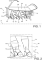
- the blade 14 also includes a radially external plate 18 (visible at the figure 1 ), which delimits, with a fixed wall 19 of the compressor 40, the radially external part of the air flow vein.
- each plate 16, 18 is in the main form of a disk coaxial with the radial axis of rotation of the blade 14 relative to the fixed platforms of the compressor.
- Each plate 16, 18 has an annular peripheral wall 20 which is centered on the radial axis of rotation and which is located in a complementary circular orifice 21 formed in the associated fixed platform.
- Each plate 16, 18 also comprises a transverse longitudinal wall 22 which extends mainly longitudinally and transversely and which faces the other plate 16, 18.
- Each transverse longitudinal wall 22 extends mainly in the extension of the annular wall of the associated platform, to reconstitute the air circulation vein.
- the blade 14 comprises a vane 12 which extends along the main axis of the blade 14, that is to say here in the radial direction R between the two plates 16, 18.
- the blade 12 comprises an upstream longitudinal end edge 24 commonly called the leading edge, a downstream longitudinal end edge 26 commonly called the trailing edge, a pressure side wall 28 and an extrados wall 30 which transversely delimit the blade 12 and which extend longitudinally between the leading edge 24 and the trailing edge 26 and radially between the two transverse longitudinal walls 22 of the plates 16, 18.
- the circulation of air in the vein produces disturbances 32 at the connection between each radial end of the blade 12 and the transverse longitudinal wall 22 of a plate 16, 18, that is to say at the connection between the intrados wall 28 or the extrados wall 30 with the transverse longitudinal wall 22 of a plate 16, 18.
- the disturbances between the extrados wall 30 and the transverse longitudinal wall 22 of the radially internal plate 16 have been shown.
- each transverse longitudinal wall 22 of a plate 16, 18, comprises at least one fin 34 which extends by projecting relative to said transverse longitudinal wall 22 in the radial direction.
- the fin 34 forms an obstacle to the swirling flow forming at the level of the plate 16, preventing the disturbance 32 from developing further, or even causing the formation of several disturbances 33 of lesser amplitude.
- the transverse longitudinal wall 22 of the plate 16 comprises two fins 34 which are distributed transversely on either side of the blade 12. It will be understood that the invention is not limited to this embodiment, and that a different number of fins 34 can be arranged on one or the other side of the blade 12.
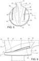
- Each fin 34 extends substantially parallel to the blade 12, that is to say in a plane parallel to the longitudinal L and vertical V directions in the mode shown in the figures.
- the fin is located transversely opposite the intrados wall 28 or the extrados wall 30 and it extends transversely at a distance from this wall 28, 30 of the blade 12.
- each fin 34 along a transverse longitudinal plane may be rectilinear, or curved, and in this case, the curvature of the fin 34 is similar to the curvature of the intrados wall 28 or of the extrados wall 30, next to which the fin 34 is located. Thus, in the latter case, the fin 34 follows the direction of flow of the air flow in the rectifier.
- Each fin 34 is delimited by a radial end face 36 and two lateral faces 38 which are separated from each other by the radial end face 36.
- the section of the fin 34 along a transverse radial plane, that is to say along the directions R, T is thus substantially rectangular.
- each fin 34 is replaced by fillets, thus forming a fin 34 with rounded edges.
- the side faces are preferably parallel to each other and parallel to the radial direction R of the blade 14.
- the radial dimension of the fin 34 is variable and increases in the longitudinal direction.
- the radial end face 36 is preferably curved in the radial direction.
- the maximum radial dimension of each fin is less than 25% of the radial dimension of the blade 12, that is to say less than 25% of the radial distance between the transverse longitudinal walls 22 of the plates 16, 18.
- This radial dimension is sufficient to combat vortices, which are of the same order of size as this radial dimension, without affecting the flow too much elsewhere.
- the radial end face 36 is flush with the transverse longitudinal wall 22 of the plate 16 at the level of the upstream longitudinal end of the fin 34. This makes it possible to avoid having an "upward step” effect, which would be detrimental to the efficiency of the turbomachine.
- the radial end face 36 is curved to extend mainly radially and to be flush with the peripheral wall 20 of the plate 16.
- the radial end face 36 is flush with, or is in the extension of, the transverse longitudinal wall 22 or the peripheral wall 20 of the plate 16.
- each fin 34 is offset longitudinally downstream relative to the leading edge 24 of the blade 12.
- this longitudinal offset downstream is at least equal to 30% of the longitudinal length of the plate 16.
- the area located at the leading edge 24 of the blade 12 is an area in which the air flow is not yet completely oriented parallel to the blade.
- An aerodynamic blocking area (at high Mach) may appear near the leading edge 24 for certain operating points; it is therefore necessary to avoid projections in this area.
- the blade 14 is rotatable relative to the stator of the compressor around a radial axis.
- the fins 34 are mounted on the plate 16, the fins 34 are also movable in rotation in a manner integral with the blade 14, guaranteeing good efficiency in straightening the air flow in the compressor and reducing the disturbances 32 commonly called "corner vortices".
- each fin 34 is made integrally with the plate 16 associated with it.
- This production can be by molding or any other method, such as by additive technology.
Landscapes
- Engineering & Computer Science (AREA)
- Mechanical Engineering (AREA)
- General Engineering & Computer Science (AREA)
- Physics & Mathematics (AREA)
- Fluid Mechanics (AREA)
- Structures Of Non-Positive Displacement Pumps (AREA)
Claims (10)
- Statorschaufel (14) mit variabler Verstellung für einen Verdichter-Gleichrichter (44) einer Turbomaschine, die sich in einer radialen Längsebene erstreckt und eine radial innere Platte (16) und eine radial äußere Platte (18) umfasst, zwischen denen sich mindestens ein Schaufelblatt (12) erstreckt,wobei jede Platte (16, 18) eine quer verlaufende Längswand (22) umfasst, die der anderen Platte (16, 18) zugewandt ist,wobei die quer verlaufende Längswand (22) mindestens einer Platte (16, 18) mindestens einen Steg (34) umfasst, der radial in Richtung der anderen Platte (16, 18) vorsteht,wobei das Schaufelblatt (12) eine erste stromaufwärtige Längsendkante (24), als Vorderkante bezeichnet, und eine zweite stromabwärtige Längsendkante (26), als Hinterkante bezeichnet, umfasst,dadurch gekennzeichnet, dass jeder Steg (34) ein stromaufwärtiges Längsende umfasst, das in Bezug auf die Vorderkante (24) in Längsrichtung stromabwärts versetzt ist.
- Schaufel (14) nach dem vorhergehenden Anspruch, dadurch gekennzeichnet, dass die quer verlaufende Längswand (22) mehrere Stege (34) umfasst, die in Querrichtung auf beiden Seiten des Schaufelblatts (12) verteilt sind.
- Schaufel (14) nach einem der vorhergehenden Ansprüche, dadurch gekennzeichnet, dass jeder Steg (34) im Wesentlichen parallel zum Schaufelblatt (12) verläuft und sich in Querrichtung in einem Abstand von dem Schaufelblatt (12) befindet.
- Schaufel (14) nach einem der vorhergehenden Ansprüche, dadurch gekennzeichnet, dass der Längsabstand zwischen dem stromaufwärtigen Längsende jedes Stegs (34) und der Vorderkante (24) mindestens 30 % der Längslänge der Platte (16, 18) beträgt.
- Schaufel (14) nach einem der vorhergehenden Ansprüche, dadurch gekennzeichnet, dass jeder Steg (34) eine radiale Endfläche (36) umfasst, die bündig mit der quer verlaufenden Längswand (22) der Platte (16, 18) am stromaufwärtigen Längsende des Stegs (34) abschließt.
- Schaufel (14) nach einem der vorhergehenden Ansprüche, wobei die Platte (16, 18) eine Umfangsfläche (20) umfasst, die sich radial von der Umfangskante der quer verlaufenden Längswand (22) erstreckt,
dadurch gekennzeichnet, dass jeder Steg (34) eine radiale Endfläche (36) umfasst, die bündig mit der Umfangsfläche der Platte (16, 18) am stromabwärtigen Längsende des Stegs (34) abschließt. - Schaufel (14) nach einem der vorhergehenden Ansprüche, dadurch gekennzeichnet, dass der Querschnitt jedes Stegs (34) entlang einer transversalen Längsebene geradlinig ist.
- Schaufel (14) nach einem der Ansprüche 1 bis 6, dadurch gekennzeichnet, dass der Querschnitt jedes Stegs (34) entlang einer transversalen Längsebene gekrümmt ist und eine ähnliche Krümmung wie die Krümmung des Schaufelblatts (12) aufweist.
- Schaufel (14) nach einem der vorhergehenden Ansprüche, dadurch gekennzeichnet, dass die maximale radiale Abmessung jedes Stegs (34) weniger als 25 % des radialen Abstands zwischen den quer verlaufenden Längswänden der Platten (16, 18) beträgt.
- Verdichter für eine Flugzeugturbomaschine, umfassend einen Gleichrichter (44), der aus einer Vielzahl von Schaufeln (14) nach einem der vorhergehenden Ansprüche ausgebildet ist, die um eine Hauptachse (A) des Verdichters verteilt sind, wobei deren Schaufelblätter (12) in Bezug auf die Hauptachse (A) des Verdichters radial ausgerichtet sind,
dadurch gekennzeichnet, dass jede Schaufel (14) drehbeweglich um ihre radiale Hauptachse montiert ist.
Applications Claiming Priority (2)
| Application Number | Priority Date | Filing Date | Title |
|---|---|---|---|
| FR1911232A FR3101914B1 (fr) | 2019-10-10 | 2019-10-10 | Aube de redresseur à calage variable comportant des ailettes aérodynamiques |
| PCT/FR2020/051723 WO2021069817A1 (fr) | 2019-10-10 | 2020-10-01 | Aube de redresseur à calage variable comportant des ailettes aérodynamiques |
Publications (2)
| Publication Number | Publication Date |
|---|---|
| EP4022171A1 EP4022171A1 (de) | 2022-07-06 |
| EP4022171B1 true EP4022171B1 (de) | 2025-01-01 |
Family
ID=69190948
Family Applications (1)
| Application Number | Title | Priority Date | Filing Date |
|---|---|---|---|
| EP20793033.0A Active EP4022171B1 (de) | 2019-10-10 | 2020-10-01 | Statorschaufel mit variabler steigung, die aerodynamische rippen aufweist |
Country Status (5)
| Country | Link |
|---|---|
| US (1) | US11859502B2 (de) |
| EP (1) | EP4022171B1 (de) |
| CN (1) | CN114502843B (de) |
| FR (1) | FR3101914B1 (de) |
| WO (1) | WO2021069817A1 (de) |
Families Citing this family (2)
| Publication number | Priority date | Publication date | Assignee | Title |
|---|---|---|---|---|
| FR3145375B1 (fr) | 2023-02-01 | 2025-02-21 | Safran | Dispositif de calage pour aube de stator a calage variable |
| FR3150240B1 (fr) * | 2023-06-20 | 2025-06-20 | Safran | Système de commande d’aubage à calage variable amélioré |
Family Cites Families (8)
| Publication number | Priority date | Publication date | Assignee | Title |
|---|---|---|---|---|
| FR2432608A1 (fr) * | 1978-07-31 | 1980-02-29 | Alsthom Atlantique | Grille d'aubes pour turbine ou compresseur |
| US6283705B1 (en) * | 1999-02-26 | 2001-09-04 | Allison Advanced Development Company | Variable vane with winglet |
| US8157504B2 (en) * | 2009-04-17 | 2012-04-17 | General Electric Company | Rotor blades for turbine engines |
| DE102009036406A1 (de) * | 2009-08-06 | 2011-02-10 | Mtu Aero Engines Gmbh | Schaufelblatt |
| FR2993021B1 (fr) * | 2012-07-06 | 2014-08-22 | Snecma | Turbomachine avec generateur de tourbillons a calage variable |
| US9533485B2 (en) * | 2014-03-28 | 2017-01-03 | Pratt & Whitney Canada Corp. | Compressor variable vane assembly |
| US10287902B2 (en) * | 2016-01-06 | 2019-05-14 | General Electric Company | Variable stator vane undercut button |
| EP3730800B1 (de) * | 2017-12-21 | 2023-12-06 | Ihi Corporation | Axialverdichter |
-
2019
- 2019-10-10 FR FR1911232A patent/FR3101914B1/fr active Active
-
2020
- 2020-10-01 CN CN202080068999.7A patent/CN114502843B/zh active Active
- 2020-10-01 EP EP20793033.0A patent/EP4022171B1/de active Active
- 2020-10-01 US US17/754,606 patent/US11859502B2/en active Active
- 2020-10-01 WO PCT/FR2020/051723 patent/WO2021069817A1/fr not_active Ceased
Also Published As
| Publication number | Publication date |
|---|---|
| CN114502843A (zh) | 2022-05-13 |
| FR3101914A1 (fr) | 2021-04-16 |
| WO2021069817A1 (fr) | 2021-04-15 |
| US11859502B2 (en) | 2024-01-02 |
| CN114502843B (zh) | 2025-05-27 |
| US20220389829A1 (en) | 2022-12-08 |
| EP4022171A1 (de) | 2022-07-06 |
| FR3101914B1 (fr) | 2021-11-12 |
Similar Documents
| Publication | Publication Date | Title |
|---|---|---|
| EP3752728B1 (de) | Strömungsmaschine für flugzeug und zugehöriges flugzeug | |
| FR3130897A1 (fr) | Turbomachine d’aéronef | |
| JP5671479B2 (ja) | 湾曲プラットフォームタービンブレード | |
| EP2673472B1 (de) | Schaufelplattformanordnung für unterschallströmungen | |
| JP5300874B2 (ja) | 非軸対称プラットフォームならびに外輪上の陥没および突起を備えるブレード | |
| EP2855847B1 (de) | Lüfterschaufel für ein strahltriebwerk eines flugzeugs mit gewölbtem profil in den fussabschnitten | |
| EP3794217B1 (de) | Turbomaschinenstatorelement | |
| CA2975570A1 (fr) | Ensemble de redressement a performances aerodynamiques optimisees | |
| WO2018138439A1 (fr) | Profil amélioré de bord d'attaque d'aubes | |
| EP4022171B1 (de) | Statorschaufel mit variabler steigung, die aerodynamische rippen aufweist | |
| FR3022295A1 (fr) | Aube de turbomachine comportant une ailette anti-tourbillons | |
| FR2956454A1 (fr) | Aube a angle de calage variable pour la prevention du decollement. | |
| EP4388178A1 (de) | Statorteil einer turbomaschine mit einem schaufelblatt und einer zwischen diesen liegenden rippe zur verringerung der oberfläche von aufwärts nach abwärts in die gasströmungsrichtung | |
| EP4508311B1 (de) | Statorteil mit rippe in einem turbinenmotor | |
| EP3827160B1 (de) | Turbinenlaufschaufel | |
| EP2976507B1 (de) | Schaufel und schaufeldihedralwinkel | |
| EP4508310B1 (de) | Statorteil mit rippe in einem turbinenmotor | |
| WO2014006310A1 (fr) | Redresseur de turbomachine avec aubes à profil ameliore | |
| FR3156485A1 (fr) | Module de turbomachine comprenant des aubes rotoriques a calage variable et des ailettes montees sur un rotor, et turbomachine correspondante | |
| EP4571076A1 (de) | Turbomaschinenmodul mit laufschaufeln und flügeln und zugehörige turbomaschine | |
| EP4630654A1 (de) | Statorteil mit schaufel- und rippenanordnung in einer turbomaschine | |
| WO2024213847A1 (fr) | Stator a calage variable ameliore et procede utilisant un tel stator | |
| FR3145377A1 (fr) | Aubage de redresseur pour une turbomachine d’aeronef | |
| WO2024033065A1 (fr) | Aube à calage variable de stator de turbomachine d'aéronef et turbomachine d'aéronef | |
| BE1028097A1 (fr) | Aube de compresseur de turbomachine, compresseur et turbomachine munis de celle-ci |
Legal Events
| Date | Code | Title | Description |
|---|---|---|---|
| STAA | Information on the status of an ep patent application or granted ep patent |
Free format text: STATUS: UNKNOWN |
|
| STAA | Information on the status of an ep patent application or granted ep patent |
Free format text: STATUS: THE INTERNATIONAL PUBLICATION HAS BEEN MADE |
|
| PUAI | Public reference made under article 153(3) epc to a published international application that has entered the european phase |
Free format text: ORIGINAL CODE: 0009012 |
|
| STAA | Information on the status of an ep patent application or granted ep patent |
Free format text: STATUS: REQUEST FOR EXAMINATION WAS MADE |
|
| 17P | Request for examination filed |
Effective date: 20220329 |
|
| AK | Designated contracting states |
Kind code of ref document: A1 Designated state(s): AL AT BE BG CH CY CZ DE DK EE ES FI FR GB GR HR HU IE IS IT LI LT LU LV MC MK MT NL NO PL PT RO RS SE SI SK SM TR |
|
| DAV | Request for validation of the european patent (deleted) | ||
| DAX | Request for extension of the european patent (deleted) | ||
| STAA | Information on the status of an ep patent application or granted ep patent |
Free format text: STATUS: EXAMINATION IS IN PROGRESS |
|
| 17Q | First examination report despatched |
Effective date: 20230911 |
|
| GRAP | Despatch of communication of intention to grant a patent |
Free format text: ORIGINAL CODE: EPIDOSNIGR1 |
|
| STAA | Information on the status of an ep patent application or granted ep patent |
Free format text: STATUS: GRANT OF PATENT IS INTENDED |
|
| GRAS | Grant fee paid |
Free format text: ORIGINAL CODE: EPIDOSNIGR3 |
|
| GRAA | (expected) grant |
Free format text: ORIGINAL CODE: 0009210 |
|
| STAA | Information on the status of an ep patent application or granted ep patent |
Free format text: STATUS: THE PATENT HAS BEEN GRANTED |
|
| INTG | Intention to grant announced |
Effective date: 20241105 |
|
| AK | Designated contracting states |
Kind code of ref document: B1 Designated state(s): AL AT BE BG CH CY CZ DE DK EE ES FI FR GB GR HR HU IE IS IT LI LT LU LV MC MK MT NL NO PL PT RO RS SE SI SK SM TR |
|
| REG | Reference to a national code |
Ref country code: GB Ref legal event code: FG4D Free format text: NOT ENGLISH |
|
| REG | Reference to a national code |
Ref country code: CH Ref legal event code: EP |
|
| REG | Reference to a national code |
Ref country code: DE Ref legal event code: R096 Ref document number: 602020044111 Country of ref document: DE |
|
| REG | Reference to a national code |
Ref country code: IE Ref legal event code: FG4D Free format text: LANGUAGE OF EP DOCUMENT: FRENCH |
|
| REG | Reference to a national code |
Ref country code: LT Ref legal event code: MG9D |
|
| REG | Reference to a national code |
Ref country code: NL Ref legal event code: MP Effective date: 20250101 |
|
| REG | Reference to a national code |
Ref country code: AT Ref legal event code: MK05 Ref document number: 1756415 Country of ref document: AT Kind code of ref document: T Effective date: 20250101 |
|
| PG25 | Lapsed in a contracting state [announced via postgrant information from national office to epo] |
Ref country code: NL Free format text: LAPSE BECAUSE OF FAILURE TO SUBMIT A TRANSLATION OF THE DESCRIPTION OR TO PAY THE FEE WITHIN THE PRESCRIBED TIME-LIMIT Effective date: 20250101 |
|
| PG25 | Lapsed in a contracting state [announced via postgrant information from national office to epo] |
Ref country code: FI Free format text: LAPSE BECAUSE OF FAILURE TO SUBMIT A TRANSLATION OF THE DESCRIPTION OR TO PAY THE FEE WITHIN THE PRESCRIBED TIME-LIMIT Effective date: 20250101 |
|
| PG25 | Lapsed in a contracting state [announced via postgrant information from national office to epo] |
Ref country code: PL Free format text: LAPSE BECAUSE OF FAILURE TO SUBMIT A TRANSLATION OF THE DESCRIPTION OR TO PAY THE FEE WITHIN THE PRESCRIBED TIME-LIMIT Effective date: 20250101 |
|
| PG25 | Lapsed in a contracting state [announced via postgrant information from national office to epo] |
Ref country code: ES Free format text: LAPSE BECAUSE OF FAILURE TO SUBMIT A TRANSLATION OF THE DESCRIPTION OR TO PAY THE FEE WITHIN THE PRESCRIBED TIME-LIMIT Effective date: 20250101 |
|
| PG25 | Lapsed in a contracting state [announced via postgrant information from national office to epo] |
Ref country code: NO Free format text: LAPSE BECAUSE OF FAILURE TO SUBMIT A TRANSLATION OF THE DESCRIPTION OR TO PAY THE FEE WITHIN THE PRESCRIBED TIME-LIMIT Effective date: 20250401 Ref country code: IS Free format text: LAPSE BECAUSE OF FAILURE TO SUBMIT A TRANSLATION OF THE DESCRIPTION OR TO PAY THE FEE WITHIN THE PRESCRIBED TIME-LIMIT Effective date: 20250501 |
|
| PG25 | Lapsed in a contracting state [announced via postgrant information from national office to epo] |
Ref country code: HR Free format text: LAPSE BECAUSE OF FAILURE TO SUBMIT A TRANSLATION OF THE DESCRIPTION OR TO PAY THE FEE WITHIN THE PRESCRIBED TIME-LIMIT Effective date: 20250101 |
|
| PG25 | Lapsed in a contracting state [announced via postgrant information from national office to epo] |
Ref country code: LV Free format text: LAPSE BECAUSE OF FAILURE TO SUBMIT A TRANSLATION OF THE DESCRIPTION OR TO PAY THE FEE WITHIN THE PRESCRIBED TIME-LIMIT Effective date: 20250101 Ref country code: PT Free format text: LAPSE BECAUSE OF FAILURE TO SUBMIT A TRANSLATION OF THE DESCRIPTION OR TO PAY THE FEE WITHIN THE PRESCRIBED TIME-LIMIT Effective date: 20250502 |
|
| PG25 | Lapsed in a contracting state [announced via postgrant information from national office to epo] |
Ref country code: BG Free format text: LAPSE BECAUSE OF FAILURE TO SUBMIT A TRANSLATION OF THE DESCRIPTION OR TO PAY THE FEE WITHIN THE PRESCRIBED TIME-LIMIT Effective date: 20250101 Ref country code: GR Free format text: LAPSE BECAUSE OF FAILURE TO SUBMIT A TRANSLATION OF THE DESCRIPTION OR TO PAY THE FEE WITHIN THE PRESCRIBED TIME-LIMIT Effective date: 20250402 |
|
| PG25 | Lapsed in a contracting state [announced via postgrant information from national office to epo] |
Ref country code: AT Free format text: LAPSE BECAUSE OF FAILURE TO SUBMIT A TRANSLATION OF THE DESCRIPTION OR TO PAY THE FEE WITHIN THE PRESCRIBED TIME-LIMIT Effective date: 20250101 |
|
| PG25 | Lapsed in a contracting state [announced via postgrant information from national office to epo] |
Ref country code: CZ Free format text: LAPSE BECAUSE OF FAILURE TO SUBMIT A TRANSLATION OF THE DESCRIPTION OR TO PAY THE FEE WITHIN THE PRESCRIBED TIME-LIMIT Effective date: 20250101 |
|
| PG25 | Lapsed in a contracting state [announced via postgrant information from national office to epo] |
Ref country code: SE Free format text: LAPSE BECAUSE OF FAILURE TO SUBMIT A TRANSLATION OF THE DESCRIPTION OR TO PAY THE FEE WITHIN THE PRESCRIBED TIME-LIMIT Effective date: 20250101 |
|
| REG | Reference to a national code |
Ref country code: DE Ref legal event code: R097 Ref document number: 602020044111 Country of ref document: DE |
|
| PG25 | Lapsed in a contracting state [announced via postgrant information from national office to epo] |
Ref country code: SM Free format text: LAPSE BECAUSE OF FAILURE TO SUBMIT A TRANSLATION OF THE DESCRIPTION OR TO PAY THE FEE WITHIN THE PRESCRIBED TIME-LIMIT Effective date: 20250101 |
|
| PG25 | Lapsed in a contracting state [announced via postgrant information from national office to epo] |
Ref country code: DK Free format text: LAPSE BECAUSE OF FAILURE TO SUBMIT A TRANSLATION OF THE DESCRIPTION OR TO PAY THE FEE WITHIN THE PRESCRIBED TIME-LIMIT Effective date: 20250101 |
|
| PG25 | Lapsed in a contracting state [announced via postgrant information from national office to epo] |
Ref country code: IT Free format text: LAPSE BECAUSE OF FAILURE TO SUBMIT A TRANSLATION OF THE DESCRIPTION OR TO PAY THE FEE WITHIN THE PRESCRIBED TIME-LIMIT Effective date: 20250101 |
|
| PG25 | Lapsed in a contracting state [announced via postgrant information from national office to epo] |
Ref country code: EE Free format text: LAPSE BECAUSE OF FAILURE TO SUBMIT A TRANSLATION OF THE DESCRIPTION OR TO PAY THE FEE WITHIN THE PRESCRIBED TIME-LIMIT Effective date: 20250101 |
|
| PG25 | Lapsed in a contracting state [announced via postgrant information from national office to epo] |
Ref country code: RO Free format text: LAPSE BECAUSE OF FAILURE TO SUBMIT A TRANSLATION OF THE DESCRIPTION OR TO PAY THE FEE WITHIN THE PRESCRIBED TIME-LIMIT Effective date: 20250101 |
|
| PG25 | Lapsed in a contracting state [announced via postgrant information from national office to epo] |
Ref country code: SK Free format text: LAPSE BECAUSE OF FAILURE TO SUBMIT A TRANSLATION OF THE DESCRIPTION OR TO PAY THE FEE WITHIN THE PRESCRIBED TIME-LIMIT Effective date: 20250101 |
|
| PLBE | No opposition filed within time limit |
Free format text: ORIGINAL CODE: 0009261 |
|
| STAA | Information on the status of an ep patent application or granted ep patent |
Free format text: STATUS: NO OPPOSITION FILED WITHIN TIME LIMIT |
|
| 26N | No opposition filed |
Effective date: 20251002 |
|
| PGFP | Annual fee paid to national office [announced via postgrant information from national office to epo] |
Ref country code: DE Payment date: 20251020 Year of fee payment: 6 |
|
| PGFP | Annual fee paid to national office [announced via postgrant information from national office to epo] |
Ref country code: GB Payment date: 20251029 Year of fee payment: 6 |
|
| PGFP | Annual fee paid to national office [announced via postgrant information from national office to epo] |
Ref country code: FR Payment date: 20251023 Year of fee payment: 6 |