EP4020894A1 - Système de réseau à bord d'un véhicule - Google Patents
Système de réseau à bord d'un véhicule Download PDFInfo
- Publication number
- EP4020894A1 EP4020894A1 EP20856757.8A EP20856757A EP4020894A1 EP 4020894 A1 EP4020894 A1 EP 4020894A1 EP 20856757 A EP20856757 A EP 20856757A EP 4020894 A1 EP4020894 A1 EP 4020894A1
- Authority
- EP
- European Patent Office
- Prior art keywords
- onboard
- signal
- vehicle
- general
- ecu
- Prior art date
- Legal status (The legal status is an assumption and is not a legal conclusion. Google has not performed a legal analysis and makes no representation as to the accuracy of the status listed.)
- Pending
Links
- 238000004891 communication Methods 0.000 claims abstract description 88
- 238000006243 chemical reaction Methods 0.000 claims abstract description 60
- 230000006870 function Effects 0.000 description 23
- 238000012545 processing Methods 0.000 description 16
- 238000000034 method Methods 0.000 description 13
- 230000033001 locomotion Effects 0.000 description 9
- 238000012546 transfer Methods 0.000 description 7
- 239000000446 fuel Substances 0.000 description 5
- 238000002347 injection Methods 0.000 description 5
- 239000007924 injection Substances 0.000 description 5
- 238000001514 detection method Methods 0.000 description 4
- 238000010586 diagram Methods 0.000 description 4
- 239000000284 extract Substances 0.000 description 4
- 230000008859 change Effects 0.000 description 3
- 238000005286 illumination Methods 0.000 description 3
- 230000004048 modification Effects 0.000 description 3
- 238000012986 modification Methods 0.000 description 3
- 230000005540 biological transmission Effects 0.000 description 2
- 238000005315 distribution function Methods 0.000 description 2
- 230000007246 mechanism Effects 0.000 description 2
- 230000008054 signal transmission Effects 0.000 description 2
- XLYOFNOQVPJJNP-UHFFFAOYSA-N water Substances O XLYOFNOQVPJJNP-UHFFFAOYSA-N 0.000 description 2
- 102100034112 Alkyldihydroxyacetonephosphate synthase, peroxisomal Human genes 0.000 description 1
- 101000799143 Homo sapiens Alkyldihydroxyacetonephosphate synthase, peroxisomal Proteins 0.000 description 1
- 238000000848 angular dependent Auger electron spectroscopy Methods 0.000 description 1
- 238000013473 artificial intelligence Methods 0.000 description 1
- 230000008878 coupling Effects 0.000 description 1
- 238000010168 coupling process Methods 0.000 description 1
- 238000005859 coupling reaction Methods 0.000 description 1
- 230000003247 decreasing effect Effects 0.000 description 1
- 238000013135 deep learning Methods 0.000 description 1
- 238000005516 engineering process Methods 0.000 description 1
- 230000003287 optical effect Effects 0.000 description 1
- 230000002093 peripheral effect Effects 0.000 description 1
- 230000004044 response Effects 0.000 description 1
- 239000000243 solution Substances 0.000 description 1
Images


Classifications
-
- H—ELECTRICITY
- H04—ELECTRIC COMMUNICATION TECHNIQUE
- H04L—TRANSMISSION OF DIGITAL INFORMATION, e.g. TELEGRAPHIC COMMUNICATION
- H04L12/00—Data switching networks
- H04L12/28—Data switching networks characterised by path configuration, e.g. LAN [Local Area Networks] or WAN [Wide Area Networks]
- H04L12/46—Interconnection of networks
-
- H—ELECTRICITY
- H04—ELECTRIC COMMUNICATION TECHNIQUE
- H04L—TRANSMISSION OF DIGITAL INFORMATION, e.g. TELEGRAPHIC COMMUNICATION
- H04L12/00—Data switching networks
- H04L12/66—Arrangements for connecting between networks having differing types of switching systems, e.g. gateways
-
- B—PERFORMING OPERATIONS; TRANSPORTING
- B60—VEHICLES IN GENERAL
- B60R—VEHICLES, VEHICLE FITTINGS, OR VEHICLE PARTS, NOT OTHERWISE PROVIDED FOR
- B60R16/00—Electric or fluid circuits specially adapted for vehicles and not otherwise provided for; Arrangement of elements of electric or fluid circuits specially adapted for vehicles and not otherwise provided for
- B60R16/02—Electric or fluid circuits specially adapted for vehicles and not otherwise provided for; Arrangement of elements of electric or fluid circuits specially adapted for vehicles and not otherwise provided for electric constitutive elements
- B60R16/023—Electric or fluid circuits specially adapted for vehicles and not otherwise provided for; Arrangement of elements of electric or fluid circuits specially adapted for vehicles and not otherwise provided for electric constitutive elements for transmission of signals between vehicle parts or subsystems
- B60R16/0231—Circuits relating to the driving or the functioning of the vehicle
-
- B—PERFORMING OPERATIONS; TRANSPORTING
- B60—VEHICLES IN GENERAL
- B60W—CONJOINT CONTROL OF VEHICLE SUB-UNITS OF DIFFERENT TYPE OR DIFFERENT FUNCTION; CONTROL SYSTEMS SPECIALLY ADAPTED FOR HYBRID VEHICLES; ROAD VEHICLE DRIVE CONTROL SYSTEMS FOR PURPOSES NOT RELATED TO THE CONTROL OF A PARTICULAR SUB-UNIT
- B60W60/00—Drive control systems specially adapted for autonomous road vehicles
-
- H—ELECTRICITY
- H04—ELECTRIC COMMUNICATION TECHNIQUE
- H04L—TRANSMISSION OF DIGITAL INFORMATION, e.g. TELEGRAPHIC COMMUNICATION
- H04L12/00—Data switching networks
- H04L12/28—Data switching networks characterised by path configuration, e.g. LAN [Local Area Networks] or WAN [Wide Area Networks]
- H04L12/40—Bus networks
- H04L12/40006—Architecture of a communication node
- H04L12/40013—Details regarding a bus controller
-
- H—ELECTRICITY
- H04—ELECTRIC COMMUNICATION TECHNIQUE
- H04L—TRANSMISSION OF DIGITAL INFORMATION, e.g. TELEGRAPHIC COMMUNICATION
- H04L12/00—Data switching networks
- H04L12/28—Data switching networks characterised by path configuration, e.g. LAN [Local Area Networks] or WAN [Wide Area Networks]
- H04L12/40—Bus networks
- H04L2012/40208—Bus networks characterized by the use of a particular bus standard
- H04L2012/40215—Controller Area Network CAN
-
- H—ELECTRICITY
- H04—ELECTRIC COMMUNICATION TECHNIQUE
- H04L—TRANSMISSION OF DIGITAL INFORMATION, e.g. TELEGRAPHIC COMMUNICATION
- H04L12/00—Data switching networks
- H04L12/28—Data switching networks characterised by path configuration, e.g. LAN [Local Area Networks] or WAN [Wide Area Networks]
- H04L12/40—Bus networks
- H04L2012/40267—Bus for use in transportation systems
- H04L2012/40273—Bus for use in transportation systems the transportation system being a vehicle
Definitions
- the technique disclosed here belongs to a technical field related to a vehicle onboard network system.
- Patent Document 1 describes a configuration of a vehicle onboard network including hub devices (relays) such as a central gateway and an Ethernet (registered trademark)-CAN gateway. A plurality of ECUs are connected to the central gateway via Ethernet.
- hub devices such as a central gateway and an Ethernet (registered trademark)-CAN gateway.
- Ethernet registered trademark
- Patent Document 2 describes a technique of providing a gateway and a network hub (HUB) for relaying data transmission and reception between nodes of different networks in a vehicle onboard network system.
- UOB network hub
- Patent Document 2 proposes a configuration of an onboard network by providing relay devices functioning as a network hub device and a gateway device.
- Actuators mounted on a vehicle have various input/output circuit configurations, signal modes, and so forth. Therefore, interfaces between the relay devices and the actuators are to be devised. Specifically, in a case where a relay device is provided with an interface for a specific actuator, for example, the relay device might be dedicated and complicated, which leads to the possibility of cost increase and other problems.
- the technique disclosed here is directed to a vehicle onboard network system including: a central control device configured to centrally manage operation of a vehicle; a plurality of relay devices connected to the central control device in a daisy chain manner via a backbone network through which a digital signal of a predetermined protocol is transmitted, wherein each of the relay devices includes a backbone-side communication port connected to the backbone network, a plurality of device-side communication ports for signal input and output to/from onboard devices, and a first interface conversion device configured to perform interface conversion between the backbone-side communication port and the plurality of device-side communication ports, the plurality of device-side communication ports include a plurality of general-purpose communication ports to which a common input circuit and/or output circuit is connected, and a predetermined first onboard device is directly connected to a first general-purpose communication port included in the general-purpose communication ports, whereas a second interface conversion device configured to perform interface conversion is disposed between a second general-purpose communication port and a predetermined second onboard device,
- each of the relay devices includes a plurality of general-purpose communication ports to which a common input circuit and/or a common output circuit is connected.
- the communication port serving as a general-purpose port as described above, specialization and complication of the relay devices can be avoided.
- an onboard device directly connectable to a general-purpose communication port is directly connected to the general-purpose communication port, whereas for an onboard device that is difficult to connect to a general-purpose communication port, a second interface device configured to perform interface conversion for the onboard device is interposed between the onboard device and the general-purpose communication port.
- the first interface conversion device may include an analog-to-digital conversion circuit configured to convert the digital signal to an analog signal
- the general-purpose communication ports may be analog ports to/from each of which the analog signal is input or output
- the second interface conversion device may include a regulator circuit disposed between the general-purpose communication port and the predetermined second onboard device.
- analog devices having different driving capacities can be connected to a common communication port.
- the second interface conversion device and the second onboard device may be configured as one unit.
- the second onboard device may include a sensor and an actuator
- the vehicle onboard network system may further include an autonomous control circuit configured to autonomously control the actuator based on an output signal from the sensor with respect to a predetermined specific operation.
- the technique disclosed here can avoid complication of relay devices and maximize versatility of the relay devices.
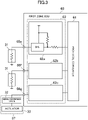
- FIG. 1 schematically illustrates a part of a vehicle onboard network system 1 according to this embodiment.
- a vehicle 10 on which the vehicle onboard network system 1 is mounted is an automobile enabling assisted driving with assistance to driver's operation and autonomous driving without driver's operation, as well as manual driving by driver's operation.
- a X-by-wire technology of performing electrical control is employed in driving control, braking control, and steering control. That is, in this vehicle, operation of an accelerator pedal, operation of a brake pedal, and operation of a steering wheel are detected by sensors, and actuators are operated in response to control signals based on outputs from these sensors.
- the vehicle onboard network system 1 includes onboard devices of a plurality of types.
- the onboard devices include a basic device related to basic operation of the vehicle, such as driving, braking, or steering, and a body-related device not related to any of driving, braking, and steering.
- the onboard device illustrated in FIG. 1 is an example of an onboard device included in the vehicle onboard network system 1, and does not exclude the vehicle onboard network system 1 from including onboard devices other than the onboard devices illustrated in FIG. 1 .
- Examples of the basic device include a driving-system device 11, an electric power steering device (hereinafter referred to as an EPS device 12), an automatic transmission, an electric brake device, and a dynamic stability control (DSC) device.
- the driving-system device 11 includes, for example, a throttle valve, a valve opening/closing mechanism, a fuel injection valve, a brake switch, and an air flow sensor.
- the EPS device 12 includes, for example, an electric motor, a steering switch, a steering warmer, and, in the case of a hydraulic system, an oil pump.
- Examples of the body-related device include a power window device (hereinafter referred to as a P/W device 21), a key less entry device 22, a wiper device, a grille shutter, a headlamp 31, a fog lamp, a horn, and a security alarm.
- the headlamp 31 is an example of a first onboard device.
- the vehicle 1 is divided into plurality of (seven in this embodiment) zones each of which is provided with a zone ECU 60.
- the central ECU 50 is connected to these zone ECUs 60 in a daisy chain manner, thereby constituting a backbone network MNW.
- the central ECU 50 is an example of a central control device, and the zone ECUs 60 are examples of relay devices.
- the backbone network MNW is configured to transmit a digital signal of a predetermined protocol.
- the predetermined protocol is not specifically limited, and is, for example, a protocol enabling high-speed large-capacity signal transmission, such as an Ethernet protocol or a CAN-FD protocol.
- a signal transmitted in the backbone network will also be referred to as a backbone network signal.
- a signal transmission path from each zone ECU 60 to the onboard device will also be referred to as a "device-side network.”
- the central ECU 50 receives signals from a plurality of sensors 100 mounted on the vehicle 10.
- the central ECU 50 generates a control signal for controlling onboard devices mounted on the vehicle, based on, for example, environment information inside and outside the vehicle acquired from the sensors 100 and/or a network (not shown) outside the vehicle.
- control signals for controlling the onboard devices are basically generated in the central ECU 50, and transmitted from the central ECU 50 to the onboard devices via the zone ECUs 60, for example.
- the sensors 100 include a plurality of cameras 101 (see FIG. 2 ) that are disposed on, for example, the vehicle body and take images of a vehicle-outside environment, and a plurality of radars 102 (see FIG. 2 ) that are disposed on, for example, the vehicle body and detect an external target or other objects.
- the sensors 100 include a position censor, a passenger state sensor, a brake pedal sensor, a steering angle sensor, an accelerator pedal sensor, an outdoor air temperature sensor, an air conditioner pressure sensor, a fuel sensor, a mat sensor, a tank internal pressure sensor, a wheel speed sensor, a brake oil sensor, a Mastervac pressure sensor, a boost sensor, a clutch stroke sensor.
- the position censor detects a position of the vehicle (vehicle positional information) by using a global positioning system (GPS).
- the passenger state sensor acquires a state of a passenger of the vehicle including the presence/absence of the passenger.
- a brake pedal sensor acquires a pressing amount of the brake pedal by a driver of the vehicle.
- the steering angle sensor acquires a steering angle in steering by the driver of the vehicle.
- the accelerator pedal sensor acquires a pressing amount of an accelerator pedal by the driver of the vehicle.
- the sensors 100 here are example of sensors for providing the central ECU 50 with information for controlling operation of the vehicle 10. That is, in this embodiment, it is not excluded that information is input to the central ECU 50 from a sensor except for the sensors described above.
- Each of the cameras 101 is disposed to capture an image of the surroundings of the vehicle by 360° in the horizontal direction. Each camera 101 captures an optical image showing a vehicle-outside environment to generate image data. Each camera 101 transmits the generated image data to the central ECU 50.
- each of the radars 102 is disposed such that the detection range expands around the vehicle by 360° in the horizontal direction. Information acquired by the radars 102 is transmitted to the central ECU 50.
- the types of the radars 102 are not specifically limited, and a millimeter radar or an infrared radar may be used, for example.
- Output signals from the sensors 100 may be directly input to the central ECU 50 in a manner similar to the information from the cameras 101 and the radars 102, or may be input to the central ECU 50 via the zone ECUs 60 or other ECUs, for example.
- the central ECU 50 includes a recognizer 51, a route calculator 52, a vehicle motion manager 53, and a body-related manager 54.
- the central ECU 50 is, for example, a processor constituted by one or more chips.
- the recognizer 51 recognizes environment information inside and outside the vehicle by using an artificial intelligence (AI) function, based on environment information from the cameras 101 and the radars 102.
- the route calculator 52 calculators a route on which the vehicle is to travel, based on vehicle-outside environment information recognized by the recognizer 51.
- the vehicle motion manager 53 calculates a target output of the basic device based on the vehicle-outside environment information recognized by the recognizer 51 and the route calculated by the route calculator 52.
- the body-related manager 54 controls operation of the body-related device based on the vehicle-outside environment information recognized by the recognizer 51 and the route calculated by the route calculator 52.
- the central ECU 50 calculates a driving force, a braking force, and a steering angle to be output by each onboard device based on a detection value of the accelerator pedal sensor, the brake pedal sensor, or sensors of the steering system, for example.
- the central ECU 50 generates a target signal indicating target values of the calculated driving force, braking force, and steering angle, that is, a driving force, a braking force, and a steering angle to be obtained by each onboard device.
- the central ECU 50 takes target motion of the vehicle 10 described later into account in calculating a driving force, a braking force, and a steering angle.
- the central ECU 50 recognizes vehicle-outside environment information by the recognizer 51, and calculates a route on which the vehicle 10 is to travel by the route calculator 52.
- the central ECU 50 determines target motion of the vehicle 10 to follow the route calculated by the route calculator 52.
- the recognizer 51 receives information from the sensors 100 and recognizes vehicle-outside environment information of the vehicle 10.
- vehicle-outside environment information includes a state of a target, a road condition, an ambient brightness, and so forth.
- Information on a target includes a relative position and a relative velocity of the target relative to the own vehicle, an attribute of the target (e.g., type and direction of movement), and so forth. Examples of the type of the target include other vehicles, pedestrians, roads, and road lane marking.
- the road information includes information on the shape of the road itself.
- the information on the road shape includes the shape of a traveling route (e.g., linear, curve, and curvature), a traveling route width, the number of lanes, the width of each lane, and so forth.
- the recognizer 51 combines images of the outside of the vehicle captured by the cameras 101 and a recognition result of the target with information such as a relative distance from the target obtained by the radars 102, and creates a 3D map showing a vehicle-outside environment. Based on the created 3D map, the recognizer 51 creates a 2D map for calculating a travel route of the vehicle 10.
- the route calculator 52 calculates a travel route of the vehicle 10. More specifically, based on the 2D map, the route calculator 52 calculates a travel route for avoiding an obstacle recognized by the recognizer 51.
- the route calculator 52 calculates a plurality of candidate routes by a state lattice method, for example, and based on a route cost, selects one or more candidate routes from these candidate routes.
- the routes may be calculated by other techniques.
- the vehicle motion manager 53 determines target motion of the vehicle for following a calculated travel route, and calculates a driving force, a braking force, and a steering angle for achieving the determined target motion.
- the vehicle motion manager 53 generates a target signal indicating target states of the calculated driving force, braking force, and steering angle, that is, a driving force, a braking force, and a steering angle to be obtained by each basic device.
- the central ECU 50 transmits the generated target signal to the zone ECUs 60, as a digital signal of the predetermined protocol described above, via the backbone network MNW
- the body-related manager 54 generates control signals to body-related devices not related to any of driving control, braking control, and steering control of the vehicle 10, based on the recognized vehicle-outside environment information and the calculated travel routes. For example, if the recognizer 51 recognizes that the surroundings are dark, the body-related manager 54 generates a control signal to be sent to the headlamp 31 so as to turn on the headlamp 31, or if a window is open when the vehicle enters a tunnel, the body-related manager 54 generates a control signal to be sent to the P/W control device 21 so as to close a window. These control signals of the body-related device are also output as digital signals of the predetermined protocol described above.
- the body-related manager 54 estimates a passenger's condition in the cabin by using a learned model generated by deep learning, based on information obtained by sensors for detecting the passenger' condition.
- the passenger's condition refers to a physical condition or feeling of a passenger. Examples of the physical condition of the passenger include healthy, mild fatigue, poor physical condition, and decreased consciousness. Examples of the passenger's feeling include fun, normal, bored, frustrated, and unpleasant.
- the body-related manager 54 generates control signals in consideration of the passenger's physical condition and/or the passenger's feeling. For example, if it is estimated that the temperature in the cabin is high and the passenger feels ill, the body-related manager 54 actuates an air conditioner and/or actuates the P/W control device 21 to open a window.
- Each zone ECU 60 includes a communication port for connection to the backbone network MNW (hereinafter referred to as a backbone port) and a plurality of device-side communication ports for signal input/output to/from onboard devices.
- the backbone port is, for example, a port conforming to the Ethernet protocol.
- the central ECU 50 and each of the zone ECUs 60 are connected to each other, and the zone ECUs 60 are connected to one another by, for example, Ethernet communication cables.
- the zones may be defined in any manner, and if the number of zones varies, the number of zone ECUs 60 varies accordingly.
- a plurality of zone ECUs 60 may be disposed in one zone.
- the zone ECU 60 disposed in the right front of the vehicle will be referred to as a first zone ECU 60.
- An example of the first zone ECU 60 will be described below.
- the first zone ECU 60 includes a protocol converter 61, a first signal converter 62, a second signal converter 63, and a third signal converter 64.
- the first zone ECU 60 includes a backbone port 65.
- the first zone ECU 60 includes communication ports 66a through 66c and 66e through 66k as device-side communication ports to be connected to the device-side network.
- the protocol converter 61, the first signal converter 62, the second signal converter 63, and the third signal converter 64 are examples of the first interface conversion device.
- the communication ports 66a through 66c are general-purpose digital communication ports, and onboard devices conforming to a CAN protocol can be connected to these ports.
- the communication ports 66e through 66f are general-purpose analog output ports, and the left and right headlamps 31 and 31 and an analog-driven actuator are connected to these ports.
- the communication ports 66e and 66f are general-purpose digital input ports, and a digital switch 106, for example, is connected to these ports.
- the communication ports 66j and 66k are general-purpose analog input ports, and an analog sensor, for example, is connected to these ports.
- the zone ECUs 60 include general-purpose ports of the same type.
- the communication ports of the same type are provided in the zone ECUs 60 and these communication ports are configured to have general-purposes so that a network system avoiding dedication and complication of the zone ECUs can be achieved.
- modification of the zone ECUs 60 can be minimized.
- the zone ECU 60 (first zone ECU 60 in this example) and a peripheral configuration thereof will be specifically described below.
- the protocol converter 61 includes: (a) the function of relaying communication between the central ECU 50 connected to the backbone port 65 and the zone ECU 60, that is, a relay function of the backbone network MNW; (b) the distribution function of extracting and distributing a signal for an onboard device connected to the own ECU from backbone network signals; and (c) the collection function of collecting data to be transmitted from the onboard device connected to the own ECU to the central ECU 50 and/or other zone ECUs 60.
- the (a) relay function is not significantly related to the technique disclosed here, and thus, will not be described in detail here, and the (b) distribution function and the (c) collection function will be mainly described below.
- the protocol converter 61 receives a backbone network signal through the backbone port 65 and performs protocol conversion on this signal.
- a backbone network signal conforming to an Ethernet protocol is subjected to protocol conversion to be converted to a digital conversion signal conforming to, for example, a controller area network (CAN) protocol, a CAN with flexible data-rate (CAN-FD) protocol, or a local interconnect network (LIN) protocol.
- CAN controller area network
- CAN-FD CAN with flexible data-rate
- LIN local interconnect network
- the protocol converter 61 extracts signals for onboard devices connected to the communication ports 66a through 66c from the digital conversion signals described above, and outputs the extracted signals from the communication ports 66a through 66c.
- the protocol converter 61 extracts signals for onboard devices connected to the communication ports 66e through 66g from the digital conversion signals described above, and outputs the extracted signals to the first signal converter 62.
- the protocol converter 61 extracts signals for onboard devices connected to the communication ports 66h and 66i from the digital conversion signals described above, and outputs the extracted signals to the second signal converter 63.
- the protocol converter 61 extracts signals for onboard devices connected to the communication ports 66j and 66k from the digital conversion signals, and outputs the extracted signals to the third signal converter 64.
- the communication port 66a is connected to, for example, an engine ECU 41, which is connected to the driving-system device 11.
- the communication port 66b is connected to, for example, an EPS-EPC 42, which is connected to the EPS device 12.
- the communication port 66c is connected to, for example, the P/W control device 21, which is connected to a P/W switch 21c and a P/W motor 21d.
- the communication port 66c is connected to, for example, the key less entry device 22.
- the communication ports 66e and 66f are respectively connected to, for example, the left and right headlamps 31 and 31.
- the communication port 66g is connected to, for example, a signal conversion device 32, which is connected to an analog-driven actuator 33.
- the communication ports 66h and 66i are respectively connected to, for example, the digital switches 106 and 106.
- the communication port 66j is connected to, for example, an analog sensor 107.
- the communication port 66k is connected to, for example, a signal conversion device 35, which is connected to an analog sensor 108.
- the signal conversion device 35 is an example of a second interface conversion device.
- the engine ECU 41 includes a first arithmetic unit 41a and a first signal processing unit 41b.
- the first arithmetic unit 41a calculates a controlled variable of the driving-system device 11 such that the driving-system device 11 obtains a target driving force, based on a signal of a target driving force transferred from the central ECU 50.
- Examples of the controlled variable of the driving-system device 11 include an opening degree of a throttle valve and an injection timing of a fuel injection valve.
- the first signal processing unit 41b generates and outputs an analog signal to each actuator of the driving-system device 11 so as to obtain the controlled variable calculated by the first arithmetic unit 41a.
- the engine ECU 41 may be configured to generate a control signal of the driving-system device 11, irrespective of communication contents between the central ECU 50 and the engine ECU 41. For example, if an engine water temperature detected by an engine water temperature sensor is high and knocking might occur in the engine, the engine ECU 41 generates a control signal to retard an injection timing of a fuel injection valve or an ignition timing of an ignition plug without passing through the central ECU 50. As described above, the engine ECU 41 has a reflection control function of controlling the driving-system device 11 without passing through the central ECU 50. A sensor 110 used for such a reflection control function is not connected to the zone ECUs 60 but is directly connected to an onboard device side (to the engine ECU 41 in this embodiment).
- the EPS-ECU 42 includes second arithmetic unit 42a and a second signal processing unit 42b.
- the second arithmetic unit 42a calculates a controlled variable of the EPS device 12 such that the EPS device 12 obtains a target steering angle, based on information of a target steering angle transferred from the central ECU 50.
- the controlled variable of the EPS device 12 is, for example, a current amount supplied to an electric motor for assistance.
- the second signal processing unit 42b generates and outputs an analog signal to the EPS device 12 so as to obtain the controlled variable calculated by the second arithmetic unit 42a.
- the EPS-ECU 42 may be configured to generate a control signal for the EPS device 12, irrespective of communication contents between central ECU 50 and the EPS-ECU 42.
- the EPS-ECU 42 in a case where the controlled variable of the steering angle greatly deviates from an actually measured value of the steering angle sensor, the EPS-ECU 42 generates a control signal to reduce the difference in the steering angle, without passing through the central ECU 50.
- the EPS-ECU 42 has the reflection control function of controlling the engine system 11 without passing through the central ECU 50.
- the sensor 111 for use in such a reflection control function is not directed to the zone ECU 60 but is directly connected to the onboard device side (the EPS-ECU 42 in this embodiment).
- the EPS-ECU 42 is configured to directly acquire outputs of at least a steering angle sensor, a vehicle speed sensor, and an engine speed sensor, for example.
- the P/W control device 21 includes a signal converter 21a and a third signal processing unit 21b.
- the signal converter 21a converts P/W opening/closing control information transferred from the central ECU 50 to a signal in a mode capable of being received by the P/W motor 21d, and outputs the converted signal as an opening/closing control signal to the P/W motor 21d.
- the third signal processing unit 21b outputs an opening/closing control signal based on the operation of the P/W switch 21c to the P/W motor 21d. Operation information of the P/W switch 21c is transferred to the central ECU 50 via the first zone ECU 60.
- the third signal processing unit 21b When the third signal processing unit 21b receives a switch signal from the P/W switch 21c, the third signal processing unit 21b controls the P/W motor 21d based on the switch signal from the P/W switch 21c, independently of a control signal from the central ECU 50.
- the sensors or other devices for acquiring information having priority to an instruction from the central ECU 50 are not connected to the first zone ECU 60 but are directly connected to the onboard device side (the P/W device 21 in this embodiment).
- the signal converter 21a is an example of a second interface device.
- the P/W switch 21c is an example of a sensor.
- the P/W motor 21d is an example of an actuator.
- the third signal processing unit 21b is an example of an autonomous control circuit.
- the key less entry device 22 incorporates a function (fourth signal processing unit 22a) of outputting a signal to an actuator 22b (e.g., door lock mechanism). This is because the key less entry device 22 is used only for locking and unlocking a door lock based on an on/off signal, and a signal itself is a simple signal.
- an actuator 22b e.g., door lock mechanism
- the key less entry device 22 directly receives a signal concerning only actuation of the key less entry device 22 among signals from the sensors 100.
- the key less entry device 22 includes the fourth signal processing unit 22a, the actuator 22b, and a receiver 22c that receives a signal from a portable terminal 104 held by a passenger.
- the fourth signal processing unit 22a converts the control signal to an analog signal.
- the fourth signal processing unit 22a transfers the converted analog signal to the actuator 22b and actuates the actuator 22b.
- a control signal from the central ECU 50 is a control signal generated by the central ECU 50 based on vehicle-outside environment information obtained from outputs of the sensors 100 and concerning an external environment of the vehicle. This control signal is a control signal for actuating the key less entry device 22, independently of a signal from the portable terminal 104 described above.
- FIG. 3 is an example of a circuit configuration of the first signal converter 62.
- the first signal converter 62 includes a plurality of (three in FIG. 3 ) analog output circuits having the same configuration.
- the first signal converter 62 includes an analog output circuit 62a connected to the communication port 66e, an analog output circuit 62b connected to the communication port 66f, and an analog output circuit 62c connected to the communication port 66g.
- FIG. 3 does not show the output circuits 62b and 62c, the analog output circuits 62a through 62c, for example, are the same circuit.
- the "same configuration” includes a circuit configuration in which parameters of elements and circuits, such as a driving capacity, a resistance value, and a capacitance value of a transistor, are different from one another, as well as completely the same circuit configuration including the same parameters of elements and circuits.
- the "same configuration” also includes a case where configurations for obtaining a main function are the same.
- As the output circuit a circuit having high versatility is preferably employed, for example. The same holds for a digital input circuit, an analog input circuit, and a digital output circuit described later.
- the analog output circuits 62a and 62b receive control signals (on/off control signals) of the headlamps 31 extracted by the protocol converter 61, and based on the control signals, convert the control signals to analog signals and output the analog signals.
- the output signals from the analog output circuits 62a and 62b are directly input to the headlamps 31.
- the interposition of an IPS device enables on/off control of the left and right headlamps 31 based on the output signals from the analog output circuits 62a and 62b. That is, the headlamps 31 receive analog control signals for actuation, directly from the first zone ECU 60.
- an actuator capable of being directly driven by a general-purpose output circuit is directly connected to the first signal converter 62. That is, such an actuator is directly connected to the communication port 66e through, for example, a connector (not shown).
- the configuration of the analog output circuit is not limited to the configuration illustrated in FIG. 3 , and may be other circuit configurations.
- examples of the onboard device configured to be driven by an output circuit having a general-purpose configuration include a horn such as a burglar horn (anti-theft horn), a power outlet (voltage converter), a glove box illumination, a door illumination, a license lamp, a shift lock solenoid, a rear fog lamp, a high mounted stop lamp, a cargo lamp, an E-latch motor, a fuel lid opener, a canister, and a rear wiper.
- a horn such as a burglar horn (anti-theft horn), a power outlet (voltage converter), a glove box illumination, a door illumination, a license lamp, a shift lock solenoid, a rear fog lamp, a high mounted stop lamp, a cargo lamp, an E-latch motor, a fuel lid opener, a canister, and a rear wiper.
- the analog output circuit 62c receives a control signal for controlling the actuator 33 extracted in the protocol converter 61, converts the control signal to an analog signal, and outputs the analog signal from the communication port 66g.
- the signal conversion device 32 is interposed between the communication port 66g and the actuator 33.
- the signal conversion device 32 has the function of converting the analog signal output from the analog output circuit 62c to a signal in a mode capable of driving an actuator in a later stage.
- the signal conversion device 32 is an example of a second interface device.
- Examples of an onboard device having difficulty in driving with a general-purpose output circuit and preferably having interposition of the signal conversion device 32 include a rear combination lamp, an electric fan of a PWM control method, an inverted wiper motor, an air conditioner actuator, a blower motor of a PWM control method, a PTC heater, an engine spark control (ESCL), an inner mirror, an indicator assy, a rear shade, a backup siren, a sunroof motor, and a change lever assy.
- a rear combination lamp an electric fan of a PWM control method, an inverted wiper motor, an air conditioner actuator, a blower motor of a PWM control method, a PTC heater, an engine spark control (ESCL), an inner mirror, an indicator assy, a rear shade, a backup siren, a sunroof motor, and a change lever assy.
- ESL engine spark control
- FIG. 4 illustrates an example of the circuit configuration of the second signal converter 63.
- the second signal converter 63 includes a plurality of (two in FIG. 4 ) digital input circuits having the same configuration. Specifically, in FIG. 4 , the second signal converter 63 includes a digital input circuit 63a connected to the communication port 66h, and a digital input circuit 63b connected to the communication port 66i.
- the configuration of the digital input circuit is not limited to the configuration of FIG. 4 , and may be other circuit configurations.
- the digital input circuit 63a is configured to transfer an input signal from the digital switch 106 connected to the communication port 66h, to the protocol converter 61.
- the digital input circuit 63b is configured to transfer an input signal from the digital switch 106 connected to the communication port 66i, to the protocol converter 61.
- FIG. 5 illustrates an example of the circuit configuration of the third signal converter 64.
- the third signal converter 64 includes a plurality of (two in FIG. 4 ) analog input circuits having the same configuration. Specifically, the third signal converter 64 includes an analog input circuit 64a connected to the communication port 66j, and an analog input circuit 64b connected to the communication port 66k.
- the analog input circuit 64a is configured to transfer an input signal (e.g., detection signal) from the analog sensor 107 connected to the communication port 66j, to the protocol converter 61.
- the protocol converter 61 transfers an output result of the analog sensor 107 to the central ECU 50 and other zone ECUs.
- Examples of the onboard device connectable to an input circuit having a general-purpose configuration include sensors such as an outdoor air temperature sensor, a hood switch, a horn switch, an EVA sensor, an in-car sensor, and an accelerator pedal sensor, and switches such as a brake switch, a manual mode switch, a seatbelt switch, a cargo switch, a mode switch, an EPB switch, a parking switch, a tank internal pressure sensor, and a centralized lock switch.
- sensors such as an outdoor air temperature sensor, a hood switch, a horn switch, an EVA sensor, an in-car sensor, and an accelerator pedal sensor, and switches such as a brake switch, a manual mode switch, a seatbelt switch, a cargo switch, a mode switch, an EPB switch, a parking switch, a tank internal pressure sensor, and a centralized lock switch.
- the analog input circuit 64b is configured to transfer an input signal (e.g., detection signal) from the analog sensor 108 to the protocol converter 61 through the signal conversion device 35.
- the protocol converter 61 transfers an output result of the analog sensor 108 to the central ECU 50 and other zone ECUs.
- the signal conversion device 35 is configured such that the analog sensor 108 can be connected to the common analog input circuit 64b in a case where the analog sensor 108 requires an additional terminal and/or an additional circuit in addition to the common analog input circuit 64b.
- Examples of an onboard device for which processing is difficult with a general-purpose input circuit and interposition of the signal conversion device 35 is recommended include a current sensor for a battery, an ultrasonic sensor, an intrusion sensor, a rain sensor, a sunroof sensor, a steering angle sensor, a combination switch, a cluster switch, an air conditioner switch, a camera, and an ADAS radar.
- the common general-purpose communication port is provided to the zone ECUs 60, and a predetermined onboard device connectable to this general-purpose communication port (corresponding to a first onboard device) is directly connected to the general-purpose communication port.
- a predetermined onboard device connectable to this general-purpose communication port (corresponding to a first onboard device) is directly connected to the general-purpose communication port.
- an interface conversion device that performs interface conversion as in a signal conversion circuit is interposed. Accordingly, specialization and complication of the zone ECUs can be avoided. Accordingly, versatility of zone ECUs disposed at various locations in the vehicle can be maximized, and at least one of parts, members, circuit configurations, or specifications, for example, can be made common among the zone ECUs.
- the functions mounted on the zone ECUs 60 are functions as hub devices such as protocol conversion.
- an ECU having an interface conversion function is interposed between the zone ECU 60 and the onboard devices.
- the zone ECUs are not provided with interfaces dedicated to onboard devices so that modification of the zone ECUs 60 by, for example, a change of connection target of the onboard device and/or a change of function of the onboard device itself can be minimized.
- the engine ECU 41 and the EPS-EPC 42 are described as examples of the ECU having the interface conversion function described above, but the disclosure is not limited to these examples.
- the ECU include an ECU for dynamic stability control (DSC), an ECU for tilt and telescopic, an ECU for an air bag, an ECU for power-train control module (PCM), an ECU for a TCM, an ECU for a 4WD unit, an ECU for a PLG, an ECU for an OHC, an ECU for an LFU, an ECU for a seat, an ECU for a connectivity master unit (CMU), and an ECU for a tuner amplifier unit (TAU).
- DSC dynamic stability control
- PCM power-train control module
- a wheel speed sensor To the ECU for a DSC, a wheel speed sensor, a brake oil sensor, a Mastervac pressure sensor, a boost sensor, and a clutch stroke sensor, for example, are connected as onboard devices.
- a tilt and telescopic motor/sensor/switch To the ECU for a tilt and telescopic, a tilt and telescopic motor/sensor/switch, for example, is connected as onboard devices.
- a brake switch and an air flow sensor To the ECU for a PCM, a brake switch and an air flow sensor, for example, are connected as onboard devices.
- a coupling assy and an oil temperature sensor To the ECU for a 4WD unit, a coupling assy and an oil temperature sensor, for example, are connected as onboard devices.
- a PLG buzzer To the ECU for a PLG, a PLG buzzer, a PLG motor/sensor/switch, a closer motor/switch, a touch sensor, and a room spot lamp, for example, are connected as onboard devices.
- a center room lamp To the ECU for an OHC, a center room lamp, a vanity mirror illumination, and a sunroof switch, for example, are connected as onboard devices.
- an LF antenna and a door handle switch To the ECU for an LFU, an LF antenna and a door handle switch, for example, are connected as onboard devices.
- a seat warmer/sensor and a power seat motor/sensor/switch To the ECU for a seat, a seat warmer/sensor and a power seat motor/sensor/switch, for example, are connected as onboard devices.
- the central ECU 50 may also serve as the function of the zone ECUs 60.
- an SSB switch, an accelerator pedal sensor, a not parking switch, a brake switch, and an ESCL are directly connected as onboard devices to the central ECU 50.
- each of the signal conversion devices 32 and 35 may include a regulator circuit disposed between a communication port and a predetermined onboard device.
- onboard devices having different driving capacities can be connected to a general-purpose port.
- the signal conversion device 35 is shown as a separate device from the analog sensor 108.
- the signal conversion device 35 and the analog sensor 108 may be separately configured or may be configured as one unit. The same holds for the signal conversion device 32 and the actuator 33.
- the signal conversion device 32 and the signal conversion device 35 are examples of a second interface device.
- the analog sensor 108 and the actuator 33 are examples of a second onboard device.
- the technique disclosed here can avoid complication of relay devices and maximize versatility of the relay devices in a vehicle control system, and thus, is significantly useful.
Landscapes
- Engineering & Computer Science (AREA)
- Computer Networks & Wireless Communication (AREA)
- Signal Processing (AREA)
- Automation & Control Theory (AREA)
- Mechanical Engineering (AREA)
- Human Computer Interaction (AREA)
- Transportation (AREA)
- Small-Scale Networks (AREA)
Applications Claiming Priority (2)
| Application Number | Priority Date | Filing Date | Title |
|---|---|---|---|
| JP2019158739A JP7411355B2 (ja) | 2019-08-30 | 2019-08-30 | 車載ネットワークシステム |
| PCT/JP2020/030221 WO2021039350A1 (fr) | 2019-08-30 | 2020-08-06 | Système de réseau à bord d'un véhicule |
Publications (2)
| Publication Number | Publication Date |
|---|---|
| EP4020894A1 true EP4020894A1 (fr) | 2022-06-29 |
| EP4020894A4 EP4020894A4 (fr) | 2022-10-19 |
Family
ID=74683807
Family Applications (1)
| Application Number | Title | Priority Date | Filing Date |
|---|---|---|---|
| EP20856757.8A Pending EP4020894A4 (fr) | 2019-08-30 | 2020-08-06 | Système de réseau à bord d'un véhicule |
Country Status (5)
| Country | Link |
|---|---|
| US (1) | US11671284B2 (fr) |
| EP (1) | EP4020894A4 (fr) |
| JP (1) | JP7411355B2 (fr) |
| CN (1) | CN114340956A (fr) |
| WO (1) | WO2021039350A1 (fr) |
Cited By (2)
| Publication number | Priority date | Publication date | Assignee | Title |
|---|---|---|---|---|
| WO2023094450A1 (fr) * | 2021-11-23 | 2023-06-01 | Zf Friedrichshafen Ag | Système et procédé de commande pour un véhicule mettant en œuvre une communication par courants porteurs en ligne (plc) |
| WO2023094448A1 (fr) * | 2021-11-23 | 2023-06-01 | Zf Friedrichshafen Ag | Système de véhicule et véhicule, en particulier pour générer des paramètres de fonctionnement |
Families Citing this family (1)
| Publication number | Priority date | Publication date | Assignee | Title |
|---|---|---|---|---|
| WO2024024085A1 (fr) * | 2022-07-29 | 2024-02-01 | マツダ株式会社 | Système de commande de véhicule |
Family Cites Families (15)
| Publication number | Priority date | Publication date | Assignee | Title |
|---|---|---|---|---|
| JP2764858B2 (ja) * | 1995-11-10 | 1998-06-11 | 株式会社日立製作所 | データ伝送システム |
| JP2001043475A (ja) | 1999-07-27 | 2001-02-16 | Nsk Ltd | センサの検出信号の伝送方法 |
| JP2006270878A (ja) | 2005-03-25 | 2006-10-05 | Fujitsu Ten Ltd | データ変換装置およびデータ変換方法 |
| JP4427761B2 (ja) | 2007-08-29 | 2010-03-10 | 株式会社デンソー | 車載電子機器制御システム |
| JP2011182123A (ja) | 2010-02-26 | 2011-09-15 | Autonetworks Technologies Ltd | 通信システム、通信装置及び通信方法 |
| DE102012210057A1 (de) * | 2012-06-14 | 2013-12-19 | Continental Automotive Gmbh | Ringförmiges Netzwerk für ein Fahrzeug |
| US9260024B1 (en) * | 2013-11-17 | 2016-02-16 | Lawrence Michael Lau | Distance-based charging for electric vehicles |
| WO2017203905A1 (fr) | 2016-05-27 | 2017-11-30 | パナソニック インテレクチュアル プロパティ コーポレーション オブ アメリカ | Concentrateur de réseau, procédé de transfert, et système de réseau sur véhicule |
| JP6962697B2 (ja) | 2016-05-27 | 2021-11-05 | パナソニック インテレクチュアル プロパティ コーポレーション オブ アメリカPanasonic Intellectual Property Corporation of America | ネットワークハブ、転送方法及び車載ネットワークシステム |
| DE112016007345T5 (de) * | 2016-11-18 | 2019-06-27 | Ford Motor Company | Verfahren und vorrichtungen zum ermöglichen der fahrzeug-zu-fahrzeug-führung und -ortung |
| DE102016222741A1 (de) * | 2016-11-18 | 2018-05-24 | Continental Automotive Gmbh | Verfahren für ein Kommunikationsnetzwerk und elektronische Kontrolleinheit |
| WO2019021404A1 (fr) | 2017-07-26 | 2019-01-31 | パナソニック インテレクチュアル プロパティ コーポレーション オブ アメリカ | Dispositif de surveillance de réseau |
| CN108632801A (zh) * | 2018-05-11 | 2018-10-09 | 铠龙东方汽车有限公司 | 一种共享电动汽车的网络系统 |
| US11019183B2 (en) * | 2018-07-02 | 2021-05-25 | Intel Corporation | Network provenance with multi-interface translation |
| CN111835627B (zh) * | 2019-04-23 | 2022-04-26 | 华为技术有限公司 | 车载网关的通信方法、车载网关及智能车辆 |
-
2019
- 2019-08-30 JP JP2019158739A patent/JP7411355B2/ja active Active
-
2020
- 2020-08-06 WO PCT/JP2020/030221 patent/WO2021039350A1/fr unknown
- 2020-08-06 US US17/638,856 patent/US11671284B2/en active Active
- 2020-08-06 EP EP20856757.8A patent/EP4020894A4/fr active Pending
- 2020-08-06 CN CN202080062438.6A patent/CN114340956A/zh active Pending
Cited By (2)
| Publication number | Priority date | Publication date | Assignee | Title |
|---|---|---|---|---|
| WO2023094450A1 (fr) * | 2021-11-23 | 2023-06-01 | Zf Friedrichshafen Ag | Système et procédé de commande pour un véhicule mettant en œuvre une communication par courants porteurs en ligne (plc) |
| WO2023094448A1 (fr) * | 2021-11-23 | 2023-06-01 | Zf Friedrichshafen Ag | Système de véhicule et véhicule, en particulier pour générer des paramètres de fonctionnement |
Also Published As
| Publication number | Publication date |
|---|---|
| CN114340956A (zh) | 2022-04-12 |
| JP2021040186A (ja) | 2021-03-11 |
| JP7411355B2 (ja) | 2024-01-11 |
| WO2021039350A1 (fr) | 2021-03-04 |
| US11671284B2 (en) | 2023-06-06 |
| US20220337453A1 (en) | 2022-10-20 |
| EP4020894A4 (fr) | 2022-10-19 |
Similar Documents
| Publication | Publication Date | Title |
|---|---|---|
| EP4020894A1 (fr) | Système de réseau à bord d'un véhicule | |
| US11316926B2 (en) | In-vehicle network system | |
| JP7211237B2 (ja) | 車両制御インタフェース、車両システム、及び自動運転プラットフォーム | |
| US11643091B2 (en) | In-vehicle equipment control device | |
| WO2020250523A1 (fr) | Dispositif de commande d'alimentation pour corps mobile | |
| CN114174123B (zh) | 车辆控制系统 | |
| WO2020250524A1 (fr) | Dispositif de commande pour corps mobile | |
| EP4012981A1 (fr) | Système de réseau dans un véhicule | |
| CN106778907A (zh) | 一种基于多传感器信息融合的智能行车预警系统 | |
| JP2021020653A (ja) | 車両制御システム | |
| US11110970B2 (en) | Removable interior for reconfigurable vehicles | |
| US20200387161A1 (en) | Systems and methods for training an autonomous vehicle | |
| CN113942510A (zh) | 一种智能驾驶汽车自动拨杆换道控制器及其运行方法 | |
| CN114206700B (zh) | 车辆控制系统 | |
| CN211617614U (zh) | 一种用于智能车辆的信息感知装置 | |
| CN206938600U (zh) | 车辆驾驶时的停车安全装置 | |
| CN212172193U (zh) | 一种适用于微巴的智能网联自动驾驶系统 | |
| CN219893452U (zh) | 车载无线侦测系统 | |
| US11827223B2 (en) | Systems and methods for intersection maneuvering by vehicles | |
| KR20230114765A (ko) | 자율주행 차량의 안전 지원 시스템 | |
| KR20220112879A (ko) | 자율주행 차량의 한시적 제어권 전환 시스템 | |
| KR20230114769A (ko) | 안전성를 확보하는 가상 환경 출력 시스템 | |
| KR20230114763A (ko) | 자율주행 차량의 응급 경로 설정 시스템 | |
| KR20220115703A (ko) | 자율주행 차량의 보행자 알림 시스템 |
Legal Events
| Date | Code | Title | Description |
|---|---|---|---|
| STAA | Information on the status of an ep patent application or granted ep patent |
Free format text: STATUS: THE INTERNATIONAL PUBLICATION HAS BEEN MADE |
|
| PUAI | Public reference made under article 153(3) epc to a published international application that has entered the european phase |
Free format text: ORIGINAL CODE: 0009012 |
|
| STAA | Information on the status of an ep patent application or granted ep patent |
Free format text: STATUS: REQUEST FOR EXAMINATION WAS MADE |
|
| 17P | Request for examination filed |
Effective date: 20220325 |
|
| AK | Designated contracting states |
Kind code of ref document: A1 Designated state(s): AL AT BE BG CH CY CZ DE DK EE ES FI FR GB GR HR HU IE IS IT LI LT LU LV MC MK MT NL NO PL PT RO RS SE SI SK SM TR |
|
| REG | Reference to a national code |
Ref country code: DE Ref legal event code: R079 Free format text: PREVIOUS MAIN CLASS: H04L0012280000 Ipc: H04L0012400000 |
|
| A4 | Supplementary search report drawn up and despatched |
Effective date: 20220919 |
|
| RIC1 | Information provided on ipc code assigned before grant |
Ipc: H04L 12/40 20060101AFI20220913BHEP |
|
| DAV | Request for validation of the european patent (deleted) | ||
| DAX | Request for extension of the european patent (deleted) | ||
| STAA | Information on the status of an ep patent application or granted ep patent |
Free format text: STATUS: EXAMINATION IS IN PROGRESS |
|
| 17Q | First examination report despatched |
Effective date: 20240209 |