EP4019778B1 - Elektronisches erweiterungsmodul einer pumpenelektronik - Google Patents
Elektronisches erweiterungsmodul einer pumpenelektronik Download PDFInfo
- Publication number
- EP4019778B1 EP4019778B1 EP21206929.8A EP21206929A EP4019778B1 EP 4019778 B1 EP4019778 B1 EP 4019778B1 EP 21206929 A EP21206929 A EP 21206929A EP 4019778 B1 EP4019778 B1 EP 4019778B1
- Authority
- EP
- European Patent Office
- Prior art keywords
- extension module
- electronics
- casing
- housing
- base
- Prior art date
- Legal status (The legal status is an assumption and is not a legal conclusion. Google has not performed a legal analysis and makes no representation as to the accuracy of the status listed.)
- Active
Links
Images

Classifications
-
- H—ELECTRICITY
- H01—ELECTRIC ELEMENTS
- H01Q—ANTENNAS, i.e. RADIO AERIALS
- H01Q1/00—Details of, or arrangements associated with, antennas
- H01Q1/12—Supports; Mounting means
- H01Q1/22—Supports; Mounting means by structural association with other equipment or articles
- H01Q1/2291—Supports; Mounting means by structural association with other equipment or articles used in Bluetooth® or Wi-Fi® devices of Wireless Local Area Networks [WLAN]
-
- F—MECHANICAL ENGINEERING; LIGHTING; HEATING; WEAPONS; BLASTING
- F04—POSITIVE - DISPLACEMENT MACHINES FOR LIQUIDS; PUMPS FOR LIQUIDS OR ELASTIC FLUIDS
- F04D—NON-POSITIVE-DISPLACEMENT PUMPS
- F04D1/00—Radial-flow pumps, e.g. centrifugal pumps; Helico-centrifugal pumps
-
- F—MECHANICAL ENGINEERING; LIGHTING; HEATING; WEAPONS; BLASTING
- F04—POSITIVE - DISPLACEMENT MACHINES FOR LIQUIDS; PUMPS FOR LIQUIDS OR ELASTIC FLUIDS
- F04D—NON-POSITIVE-DISPLACEMENT PUMPS
- F04D29/00—Details, component parts, or accessories
- F04D29/007—Details, component parts, or accessories especially adapted for liquid pumps
-
- F—MECHANICAL ENGINEERING; LIGHTING; HEATING; WEAPONS; BLASTING
- F04—POSITIVE - DISPLACEMENT MACHINES FOR LIQUIDS; PUMPS FOR LIQUIDS OR ELASTIC FLUIDS
- F04D—NON-POSITIVE-DISPLACEMENT PUMPS
- F04D29/00—Details, component parts, or accessories
- F04D29/60—Mounting; Assembling; Disassembling
- F04D29/62—Mounting; Assembling; Disassembling of radial or helico-centrifugal pumps
-
- H—ELECTRICITY
- H01—ELECTRIC ELEMENTS
- H01R—ELECTRICALLY-CONDUCTIVE CONNECTIONS; STRUCTURAL ASSOCIATIONS OF A PLURALITY OF MUTUALLY-INSULATED ELECTRICAL CONNECTING ELEMENTS; COUPLING DEVICES; CURRENT COLLECTORS
- H01R12/00—Structural associations of a plurality of mutually-insulated electrical connecting elements, specially adapted for printed circuits, e.g. printed circuit boards [PCB], flat or ribbon cables, or like generally planar structures, e.g. terminal strips, terminal blocks; Coupling devices specially adapted for printed circuits, flat or ribbon cables, or like generally planar structures; Terminals specially adapted for contact with, or insertion into, printed circuits, flat or ribbon cables, or like generally planar structures
- H01R12/70—Coupling devices
- H01R12/71—Coupling devices for rigid printing circuits or like structures
-
- H—ELECTRICITY
- H01—ELECTRIC ELEMENTS
- H01R—ELECTRICALLY-CONDUCTIVE CONNECTIONS; STRUCTURAL ASSOCIATIONS OF A PLURALITY OF MUTUALLY-INSULATED ELECTRICAL CONNECTING ELEMENTS; COUPLING DEVICES; CURRENT COLLECTORS
- H01R13/00—Details of coupling devices of the kinds covered by groups H01R12/70 or H01R24/00 - H01R33/00
- H01R13/62—Means for facilitating engagement or disengagement of coupling parts or for holding them in engagement
- H01R13/621—Bolt, set screw or screw clamp
-
- H—ELECTRICITY
- H01—ELECTRIC ELEMENTS
- H01R—ELECTRICALLY-CONDUCTIVE CONNECTIONS; STRUCTURAL ASSOCIATIONS OF A PLURALITY OF MUTUALLY-INSULATED ELECTRICAL CONNECTING ELEMENTS; COUPLING DEVICES; CURRENT COLLECTORS
- H01R13/00—Details of coupling devices of the kinds covered by groups H01R12/70 or H01R24/00 - H01R33/00
- H01R13/62—Means for facilitating engagement or disengagement of coupling parts or for holding them in engagement
- H01R13/621—Bolt, set screw or screw clamp
- H01R13/6215—Bolt, set screw or screw clamp using one or more bolts
-
- H—ELECTRICITY
- H02—GENERATION; CONVERSION OR DISTRIBUTION OF ELECTRIC POWER
- H02K—DYNAMO-ELECTRIC MACHINES
- H02K11/00—Structural association of dynamo-electric machines with electric components or with devices for shielding, monitoring or protection
- H02K11/0094—Structural association with other electrical or electronic devices
-
- H—ELECTRICITY
- H05—ELECTRIC TECHNIQUES NOT OTHERWISE PROVIDED FOR
- H05K—PRINTED CIRCUITS; CASINGS OR CONSTRUCTIONAL DETAILS OF ELECTRIC APPARATUS; MANUFACTURE OF ASSEMBLAGES OF ELECTRICAL COMPONENTS
- H05K1/00—Printed circuits
- H05K1/02—Details
- H05K1/0213—Electrical arrangements not otherwise provided for
- H05K1/0215—Grounding of printed circuits by connection to external grounding means
-
- H—ELECTRICITY
- H05—ELECTRIC TECHNIQUES NOT OTHERWISE PROVIDED FOR
- H05K—PRINTED CIRCUITS; CASINGS OR CONSTRUCTIONAL DETAILS OF ELECTRIC APPARATUS; MANUFACTURE OF ASSEMBLAGES OF ELECTRICAL COMPONENTS
- H05K1/00—Printed circuits
- H05K1/02—Details
- H05K1/0296—Conductive pattern lay-out details not covered by sub groups H05K1/02 - H05K1/0295
- H05K1/0298—Multilayer circuits
-
- F—MECHANICAL ENGINEERING; LIGHTING; HEATING; WEAPONS; BLASTING
- F04—POSITIVE - DISPLACEMENT MACHINES FOR LIQUIDS; PUMPS FOR LIQUIDS OR ELASTIC FLUIDS
- F04D—NON-POSITIVE-DISPLACEMENT PUMPS
- F04D13/00—Pumping installations or systems
- F04D13/02—Units comprising pumps and their driving means
- F04D13/06—Units comprising pumps and their driving means the pump being electrically driven
- F04D13/0686—Mechanical details of the pump control unit
-
- F—MECHANICAL ENGINEERING; LIGHTING; HEATING; WEAPONS; BLASTING
- F05—INDEXING SCHEMES RELATING TO ENGINES OR PUMPS IN VARIOUS SUBCLASSES OF CLASSES F01-F04
- F05D—INDEXING SCHEME FOR ASPECTS RELATING TO NON-POSITIVE-DISPLACEMENT MACHINES OR ENGINES, GAS-TURBINES OR JET-PROPULSION PLANTS
- F05D2230/00—Manufacture
- F05D2230/50—Building or constructing in particular ways
- F05D2230/51—Building or constructing in particular ways in a modular way, e.g. using several identical or complementary parts or features
-
- H—ELECTRICITY
- H01—ELECTRIC ELEMENTS
- H01Q—ANTENNAS, i.e. RADIO AERIALS
- H01Q1/00—Details of, or arrangements associated with, antennas
- H01Q1/12—Supports; Mounting means
- H01Q1/22—Supports; Mounting means by structural association with other equipment or articles
-
- H—ELECTRICITY
- H01—ELECTRIC ELEMENTS
- H01R—ELECTRICALLY-CONDUCTIVE CONNECTIONS; STRUCTURAL ASSOCIATIONS OF A PLURALITY OF MUTUALLY-INSULATED ELECTRICAL CONNECTING ELEMENTS; COUPLING DEVICES; CURRENT COLLECTORS
- H01R12/00—Structural associations of a plurality of mutually-insulated electrical connecting elements, specially adapted for printed circuits, e.g. printed circuit boards [PCB], flat or ribbon cables, or like generally planar structures, e.g. terminal strips, terminal blocks; Coupling devices specially adapted for printed circuits, flat or ribbon cables, or like generally planar structures; Terminals specially adapted for contact with, or insertion into, printed circuits, flat or ribbon cables, or like generally planar structures
- H01R12/70—Coupling devices
- H01R12/7076—Coupling devices for connection between PCB and component, e.g. display
-
- H—ELECTRICITY
- H01—ELECTRIC ELEMENTS
- H01R—ELECTRICALLY-CONDUCTIVE CONNECTIONS; STRUCTURAL ASSOCIATIONS OF A PLURALITY OF MUTUALLY-INSULATED ELECTRICAL CONNECTING ELEMENTS; COUPLING DEVICES; CURRENT COLLECTORS
- H01R13/00—Details of coupling devices of the kinds covered by groups H01R12/70 or H01R24/00 - H01R33/00
- H01R13/46—Bases; Cases
- H01R13/502—Bases; Cases composed of different pieces
-
- H—ELECTRICITY
- H01—ELECTRIC ELEMENTS
- H01R—ELECTRICALLY-CONDUCTIVE CONNECTIONS; STRUCTURAL ASSOCIATIONS OF A PLURALITY OF MUTUALLY-INSULATED ELECTRICAL CONNECTING ELEMENTS; COUPLING DEVICES; CURRENT COLLECTORS
- H01R13/00—Details of coupling devices of the kinds covered by groups H01R12/70 or H01R24/00 - H01R33/00
- H01R13/62—Means for facilitating engagement or disengagement of coupling parts or for holding them in engagement
-
- H—ELECTRICITY
- H02—GENERATION; CONVERSION OR DISTRIBUTION OF ELECTRIC POWER
- H02K—DYNAMO-ELECTRIC MACHINES
- H02K2213/00—Specific aspects, not otherwise provided for and not covered by codes H02K2201/00 - H02K2211/00
- H02K2213/03—Machines characterised by numerical values, ranges, mathematical expressions or similar information
-
- H—ELECTRICITY
- H02—GENERATION; CONVERSION OR DISTRIBUTION OF ELECTRIC POWER
- H02K—DYNAMO-ELECTRIC MACHINES
- H02K7/00—Arrangements for handling mechanical energy structurally associated with dynamo-electric machines, e.g. structural association with mechanical driving motors or auxiliary dynamo-electric machines
- H02K7/14—Structural association with mechanical loads, e.g. with hand-held machine tools or fans
-
- H—ELECTRICITY
- H05—ELECTRIC TECHNIQUES NOT OTHERWISE PROVIDED FOR
- H05K—PRINTED CIRCUITS; CASINGS OR CONSTRUCTIONAL DETAILS OF ELECTRIC APPARATUS; MANUFACTURE OF ASSEMBLAGES OF ELECTRICAL COMPONENTS
- H05K1/00—Printed circuits
- H05K1/02—Details
- H05K1/0213—Electrical arrangements not otherwise provided for
-
- H—ELECTRICITY
- H05—ELECTRIC TECHNIQUES NOT OTHERWISE PROVIDED FOR
- H05K—PRINTED CIRCUITS; CASINGS OR CONSTRUCTIONAL DETAILS OF ELECTRIC APPARATUS; MANUFACTURE OF ASSEMBLAGES OF ELECTRICAL COMPONENTS
- H05K1/00—Printed circuits
- H05K1/02—Details
- H05K1/0296—Conductive pattern lay-out details not covered by sub groups H05K1/02 - H05K1/0295
Definitions
- the invention relates to an electronic extension module of a pump electronics of a centrifugal pump for extending the pump electronics with at least one additional function.
- the IF module provides both the electrical connection (RS485) for connecting the pump to a BACnet and the necessary communication protocol.
- WILO SE offers a similar function module under item number 2097808, which achieves a corresponding expansion of the pump using the industrial standard MODBUS.
- the two function modules are connected to the same electrical interface of the centrifugal pump unit.
- the document EP 2 975 738 A1 also shows a pluggable electronic extension module.
- a solution that meets all of these requirements is to provide functions or functional groups in modules or as a modular system in the form of electronic extension modules that complement the main product or the centrifugal pump unit or its pump electronics. This reduces development time and the time until availability on the market because development can essentially be limited to the electronic extension modules. Furthermore, no re-certification of the main product is required because certification is limited to the electronic extension modules. This means that new technologies can be combined with or integrated into the main product in a timely manner. Since extension modules can also be used to equip the main product with specific functions or functional groups as needed, unnecessary functionalities can be omitted, resulting in an overall cost advantage.
- the aforementioned extension module is particularly easy to handle due to its plug-in capability and also meets the requirements for operational safety, robustness, susceptibility to errors, contact protection, insulation and tightness.
- the additional function can be, for example, a radio-based communication technology.
- This communication technology can be, for example, Bluetooth, in particular Bluetooth Low Energy (BLE), WLAN (Wireless Local Area Network according to IEEE 802.11 standard) or mobile communications (according to a mobile communications standard for 3G, 4G, 5G mobile communications networks of the 3GPP, in particular NB-IoT via LTE and/or 5G networks).
- BLE Bluetooth Low Energy
- WLAN Wireless Local Area Network according to IEEE 802.11 standard
- mobile communications according to a mobile communications standard for 3G, 4G, 5G mobile communications networks of the 3GPP, in particular NB-IoT via LTE and/or 5G networks.
- the additional function can alternatively be a wired communication technology, in particular Modbus, BACnet, LIN bus or Ethernet.
- the additional function can be a sensor, an actuator or an electronic memory module.
- the sensor can be formed by one or more sensors, for example to detect a temperature outside the centrifugal pump, the air humidity, vibrations (acceleration sensor) of the centrifugal pump or noises (microphone).
- the actuator can be, for example, a relay that provides a potential-free contact via which the pump electronics can control an external device.
- the memory module can serve as a data logger, for example.
- the pump electronics can thus store data from the centrifugal pump in the extension module, for example operating data such as delivery head, delivery flow, power consumption, etc., or information about the occurrence of errors.
- the memory module can be the carrier of an operating configuration or a software update for the centrifugal pump, which can be transferred to the pump electronics via the extension module.
- the electrical interface serves for the pluggable electrical connection of the extension module with the pump electronics.
- this already implies a certain mechanical stability between the extension module and the pump electronics it is advantageous to keep any stress caused by mechanical forces that may be exerted on the housing of the extension module away from the electrical contacts in order to prevent any impairment of the contact or even damage to the electrical interface or the corresponding interface on the part of the pump electronics.
- connection mechanism can preferably be designed in such a way that the extension module can be detachably attached to the housing of the pump electronics, so that it can be removed again if necessary. It can be replaced by another extension module if necessary, be it due to a replacement of the extension module for repairs, a change in function or a function upgrade.
- the other extension module can therefore contain a different function, an additional function to the function of the previous extension module or the same function in a more modern version (upgrade).
- connection mechanism can, for example, be a screw fastening using at least one screw.
- at least two screws form the connection mechanism.
- the extension module is thus also protected against twisting by the connection mechanism.
- These two screws are suitably located directly next to, in particular in line with, the electrical interface.
- the housing of the extension module can have minimal lateral dimensions in one design variant.
- the screw(s) is/are designed as captive screw(s) so that it/they cannot be separated from the housing of the extension module.
- a core aspect of the invention is to provide a uniform electrical interface for different extension modules, ie extension modules with different additional functions.
- the extension modules can differ not only functionally, but also structurally in terms of their shape and/or dimensions.
- the arrangement or the distance of the two screws relative to the electrical interface determines the lower limit of the lateral housing dimensions, which can be minimal if the two screws are arranged in line with the electrical interface.
- connection mechanism is advantageous for larger extension modules to provide a connection mechanism between the extension module and the housing of the pump electronics in addition to or at least as an alternative to the screw connection, which acts at connection points that are further away from the electrical interface than the screws, in particular offset from them.
- the connection mechanism is preferably a positive connection using locking elements that protrude from the underside of the housing in order to be inserted through corresponding openings in the pump electronics housing.
- the locking elements can protrude from the bottom of the housing in the form of a block or pin.
- Their cross-section can basically be any shape, e.g. round, oval, rectangular or square.
- the locking elements can be designed in the form of latching elements and engage behind the openings in the pump electronics housing. This creates a self-locking mechanism, so that simply plugging the extension module onto the pump electronics housing creates a fixed, stable mount. Further steps to attach the extension module are therefore not necessary, which makes handling particularly easy.
- the locking elements are held in position by means of a blocking element arranged on the side of the pump electronics housing, so that they can no longer be removed from the locking position against the plug-in direction of the extension module.
- the Locking elements each have a recess for the positive reception of the aforementioned blocking element.
- the number of locking elements can be at least two, preferably four. Ideally, the locking elements are arranged in a rectangle so that the extension module is symmetrically mounted on the pump electronics housing.
- At least one locking element protrudes further from the underside of the housing than at least one other locking element.
- the locking element protruding further from the underside thereby moves forward when the extension module is plugged in and thus forms a guide at an early stage that prevents the extension module from jamming or tipping along the joining direction and ensures that the electrical interface is plugged into the corresponding electrical counter-interface of the pump electronics in an aligned, damage-free manner.
- the openings in the pump electronics housing through which the locking elements are guided correspond in terms of the shape and size of their inner contour to the outer contour of the locking elements, so that a positive connection is established.
- at least the locking element protruding further from the underside of the housing has a non-round cross-section, so that the corresponding positive connection prevents twisting.
- the free ends of the locking elements remote from the housing can be bevelled or conical. This ensures that the extension module is correctly aligned relative to the housing of the pump electronics. A lateral offset is compensated and the extension module is centered.
- the electrical interface forms a plug.
- the carrier element protrudes from a base, spaced from the underside of the housing, the electrical interface is contacted by the corresponding counter contacts deep inside the housing of the pump electronics.
- the distance between the free end of the carrier element remote from the housing and the underside of the housing is preferably at least 20mm. This helps to protect the counter contacts against contact when the extension module is not attached. Further protection can be provided by a blind plug which closes the opening in the pump electronics housing through which the electrical interface is plugged in when the extension module is not attached.
- the width of the base can be less than 14mm, in particular less than 12mm, and/or the thickness of the base can be less than 6mm, in particular less than 4.5mm.
- the contacts of the electrical interface are designed in the form of conductor tracks on the flat carrier element, the contacts take up very little space.
- the carrier element can be made relatively narrow overall.
- the carrier element protrudes from the base with a length that is greater than its width, so that the carrier element is tongue-shaped.
- the contacts on the carrier element are also positionally secure, so that, in contrast to protruding contact pins, they cannot bend when the extension module is plugged in.
- the conductor tracks can be designed on just one flat side or on both flat sides of the carrier element.
- the electrical interface can therefore have more or fewer contacts as required without its shape and dimensions having to be changed.
- the contacts comprise first electrical contacts for supplying power to the electronics inside the extension module and second electrical contacts for data transmission.
- the expansion module is therefore powered by the pump electronics, so that the expansion module basically requires neither an additional power supply connection nor a battery.
- a battery can be present in and/or a power supply connection on the expansion module for safety reasons.
- the data transmission contacts are used to transmit data in the form of electrical signals between the expansion module and the pump electronics. Depending on the additional function, this data transmission can be unidirectional or bidirectional, from the expansion module to the pump electronics and/or vice versa.
- At least one of the electrical contacts is brought closer to the edge of the free end of the carrier element than the other contacts, and this at least one electrical contact is a ground contact.
- this at least one contact close to the edge leads when the extension module is plugged in and is thus electrically contacted first.
- This allows electrostatic potentials to be reduced before the data transmission contacts are contacted. The risk of damage to an electronic component of the extension module is thus minimized.
- the ground potential is defined in the electronics before the other contacts, in particular the data transmission contacts, are contacted.
- two of the electrical contacts are brought closer to the edge of the free end of the carrier element than the other contacts, with one of these two contacts being a ground contact and the other a supply contact.
- SELV supply voltage
- the carrier element can be a printed circuit board. It can therefore be manufactured easily and inexpensively using the technology known for printed circuit boards and is only very thin.
- the counter contacts to be contacted by the pump electronics can in this case be
- the board edge connector is designed to grip the free end of the carrier element in a form-fitting and force-fitting manner like a mouth and at the same time to touch the contacts of the electrical interface by means of spring-loaded counter-contacts. This creates a reliable electrical connection.
- the housing of the expansion module can form a potting body in which the electronics are potted. This protects the electronics against dust and water, achieving at least protection class IP65.
- the potting compound forming the potting body serves as a cooling agent for the electronics, since the electronics encased in the potting compound transfer their heat directly to the potting compound.
- the casing also transfers vibrations directly to the electronics, so that no resonance can occur with a natural frequency different from the vibrations, which could potentially damage electrical contact points and/or electronic components of the electronics of the expansion module.
- the housing of the expansion module can be made up of two or more parts and define a hollow interior in which the electronics are inserted.
- the housing consists of two housing shells placed on top of each other, or of a trough-like base part and a cover that closes it, or of a base and a hood-like cover element that covers it.
- the base from which the carrier element protrudes is arranged between the electrical interface, or more precisely between the freely accessible section of the carrier element and the housing.
- the carrier element extends through the base into the interior of the housing of the expansion module, where it makes electrical contact with the electronics.
- the base thus serves to mechanically stabilize the carrier element.
- the base is integral with the underside of the housing.
- the base is part of the housing. This eliminates the need to seal a gap between the base and the housing, which would be present in an embodiment in which the underside of the Housing has an opening through which the electrical interface and base are passed.
- the one-piece design of the base and housing also gives the electrical interface more stability.
- the base is hollow and the support element is inserted through the base. This makes mounting the electronics and the support element inside the housing of the expansion module particularly easy.
- the base serves as a guide and ensures correct alignment, parallel to the joining direction.
- the carrier element is cast in the base, i.e. it is overmolded in the plastic material that forms the base. This means that no moisture or dust can get along the carrier element into the interior of the housing of the extension module or, conversely, the housing of the pump electronics.
- a synergy of this design variant exists in connection with the overmolded electronics of the extension module, since in this case the carrier element and the electronics can be cast at the same time, i.e. in a common process step.
- the base has a simply symmetrical, preferably trapezoidal, cross-section at least at the free end opposite the bottom of the housing.
- This principle known in technical jargon as poka-yoke, ensures that the extension module is plugged in with the correct orientation and thus prevents incorrect assembly, at least if this is not already achieved by the connection mechanism.
- the base can have a sealing ring at the end closest to the housing.
- This sealing ring rests on the inside of the opening in the pump electronics housing.
- the sealing ring can, for example, be molded onto the base so that it is fixed in place and cannot slip or get lost. An elastomer can be used for this. In one design variant, this plastic can also be used to fill the cavity in the base and thus close the gap or gaps between the support element and the inside of the base. To improve the sealing effect of the sealing ring, it can have two parallel sealing lips.
- the invention further relates to a centrifugal pump with pump electronics and an extension module according to the invention which is connected to the pump electronics.
- first expansion module according to the invention with a first housing size and a second expansion module according to the invention with a second housing size, the second housing size being larger than the first housing size.
- the base area of the underside of the housing of the first expansion module is larger than the base area of the underside of the housing of the second expansion module.
- the electrical interfaces of these first and second expansion modules are identical in such a way that either the first or the second expansion module can be plugged into the pump electronics.
- connection mechanism in particular the spatial arrangement of the locking elements in relation to the electrical interface. If the connection mechanism is formed by four locking elements, for example, these can be arranged in or near the corners of the underside of the housing of the smaller first expansion module, whereas in the case of the second expansion module, due to its structurally larger housing, at least two of the locking elements are set back from the corners of the underside of this housing.
- the subject matter of the invention is also a set consisting of at least a first and a second extension module of the aforementioned type, in which the base area of the underside of the first extension module is larger than the base area of the underside of the second extension module, but the electrical interface and the spatial arrangement of the locking elements with respect to the electrical interface are identical in the two extension modules.
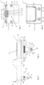
- Figures 1 to 4 show a first embodiment of a plug-in electronic extension module 1 of a pump electronics (not shown here) of a centrifugal pump for extending the pump electronics with at least one additional function.
- Figure 1 a side view
- Figure 2 a frontal view
- Figure 3 a view from below
- Figure 4 a top view.
- the additional function provided here is a wired bus interface.
- the extension module 1 comprises a housing 2, which can be detachably attached to the outside of a housing of the pump electronics (also not shown) by means of a connection mechanism 3.
- the connection mechanism 3 is implemented here in the form of a screw connection consisting of two captive screws 3. These are each located in a passage or bore 13, which extends through a side wing 19 of the housing 2.
- the assembly-side end 3a of the screws protrudes from the housing 2. It can be seen that the diameter of the screws 3 at this end 3a is larger than in the section between the housing 2 and the screw head, so that the screws 3 cannot be removed upwards from the passages 13.
- the extension module 1 has an electronics unit 12 which is housed in the housing 2 and provides the additional function and is only indicated here.
- the electronics unit 12 comprises electrical and/or electronic components, preferably on a circuit board.
- the electronics unit 12 is encapsulated in the housing 2 so that the housing forms a encapsulated body.
- a cable 10 is guided into the interior of the housing 2 on the side facing away from the pump electronics unit and is electrically connected there to the electronics unit 12. It is also encapsulated in the housing 2.
- the extension module 1 also has an electrical interface 5, which is connected to the electronics 12 by a cable for plugging in electrically connecting the extension module 1 to the pump electronics, which protrudes from the underside 2a of the housing 2 facing the pump electronics in order to be inserted through an opening in the pump electronics housing as intended.
- the electrical interface 5 comprises contacts 7a, 7b in the form of parallel conductor tracks on a flat carrier element 6, which is designed here in the manner of a printed circuit board and protrudes like a tongue from a base 8 at a distance from the underside 2a of the housing 2.
- the electrical interface 5 thus forms a plug.
- the conductor tracks or contacts 7a, 7b are designed here on only one flat side of the carrier element 6, but in another design variant they can be present on both flat sides.
- the total height H between the underside 2a of the housing 2 and the end of the carrier element 6 remote from the housing is between 22mm and 23mm. This ensures that the electrical interface 5 is contacted by corresponding counter-contacts, preferably in the form of a circuit board edge connector, deep inside the housing of the pump electronics.
- the proportion of the base 8 to the total height H is at least 50%, preferably between 60% and 65%.
- the two screws are located directly next to, or more precisely in line with, the electrical interface 5.
- the housing 2 is therefore comparatively small or narrow overall.
- the contacts 7a, 7b comprise first electrical contacts 7a for supplying power to the electronics 12 inside the extension module and second electrical contacts 7b for data transmission.
- the extension module 1 is thus supplied with power by the pump electronics.
- the data transmission contacts 7b are used for the bidirectional transmission of data in the form of electrical signals between the extension module 1 and the pump electronics.
- the first electrical contacts 7a for supplying power to the electronics 12 are brought closer to the edge 6a of the end of the carrier element 6 remote from the housing than the data transmission contacts 7b.
- One of the first electrical contacts 7a forms a ground contact, so that when plugging in the expansion module 1, the ground and the supply voltage (SELV) are connected first and only then the data lines.
- SELV supply voltage
- the front edge 6a of the carrier element 6 is chamfered on both sides and at its ends to facilitate insertion into the mating connector on the pump electronics, e.g. the circuit board edge connector.
- the base 8 is made in one piece with the housing 2, so that there is no gap and no seam between the base 8 and the housing 2.
- the carrier element 6 is cast in the base 8, i.e. it is molded around by the plastic material forming the base 8. It extends through the base 8 into the interior of the housing 2 of the expansion module 1, where it electrically contacts the electronics 12.
- the width B of the base 8 is less than 12mm.
- the thickness D of the base 8 is less than 4.5mm.
- the carrier element 6 protrudes from the base 8 with a length that is greater than its width, so that the carrier element 6 as a whole has a tongue-shaped effect.
- the base 8 consists, when viewed in detail, of a main part 8 from which the carrier element 6 protrudes, a base foot 15 which protrudes laterally, in particular on all sides, from the main part 8 and into which the main part 8 merges in the direction of the housing 2, and a base base 16 which protrudes laterally, in particular on all sides, from the base foot 15 and forms the connection between the base foot 15 and the housing 2.
- the base foot 15 goes into the base base 16 and this into the housing 2.
- the base 8 thus widens in the direction of the housing 2 twice and in a step-like manner.
- the base 8 has a simply symmetrical cross-section at its end remote from the housing. There is only mirror symmetry with respect to a single axis A. Looking more closely, the main part of the base 8 has an essentially trapezoidal cross-section, so that there is only one orientation for plugging the extension module 1 into the pump electronics.
- the base 8 has a sealing ring 11 with two parallel sealing lips 12 at the end closest to the housing, more precisely on the outer circumference of the base foot 15.
- the sealing ring 11 extends to the step-like transition where the base foot 15 merges into the base base 16.
- FIG. 5 shows a side view, Figure 6 a front view, Figure 7 a view from below and Figure 8 a top view of the second expansion module 1 according to the invention. Since the electrical interface 5 including base 8, 15, 16 and sealing ring 11 are identical to the first embodiment, reference is made to the previous explanations in this regard.
- the second expansion module 1 according to the invention expands the pump electronics with an additional function in the form of a radio interface, in particular Bluetooth, WLAN or mobile radio.
- the housing 2 is essentially box-shaped and is intended to be placed on the outside of the pump electronics housing. Its height is less than its length and width.
- the housing 2 consists of an upper part 2' and a lower part 2", between which a hollow receiving space is formed in which the electronics 12 is located.
- the lower part 2" merely forms a flat base.
- the upper part 2' is hood-like and covers the electronics 12.
- the upper and lower parts 2', 2" are connected to one another in a form-fitting, in particular locking manner.
- the base 8 is formed in one piece with the lower part 2". It is also hollow and the carrier element 6 is inserted through the base 8. The carrier element 6 and the electronics 12 are thus assembled in the joining direction of the expansion module 1.
- the extension module 1 can be attached as in the first version using two screws which are inserted into the Figures 5 to 8 However, these are not shown.
- the housing 2 also has corresponding bushings 13, as shown in the Figures 7 and 8 can be seen.
- ring-shaped recesses 14 are provided concentrically around the passages 13, in which the respective head of the screws 3 lies so that it does not protrude from the top of the upper part 2".
- a further connection mechanism is provided between the extension module 1 and the housing of the pump electronics in the form of a positive connection using four locking elements 4a, 4b. These act on connection points that are further away from the electrical interface 5 than the optional screws 3 and span the corner points of a rectangle.
- the locking elements 4a, 4b protrude from the underside of the housing 2, or more precisely the lower part 2", in order to be inserted through corresponding openings in the pump electronics housing.
- the locking elements 4a, 4b protrude in blocks from the bottom of the housing 2 and have a substantially square cross-section on the outside. For reasons of injection molding, their cross-section is, more precisely, C-shaped, which reduces the shrinkage of the plastic after injection molding. reduced.
- the housing 2 can suitably be made of a thermoplastic material. With increasing distance from the housing 2, the locking elements 4a, 4b taper in the direction of extension in the manner of a truncated pyramid. This facilitates their insertion into the corresponding openings in the pump electronics housing.
- the locking elements 4a, 4b each have a recess 9 for the positive reception of a blocking element, which is held on the pump electronics housing.
- the recesses 9 each extend transversely to the longitudinal extent of the locking elements 4a, 4b. They are each located on the side of the locking elements 4a, 4b facing away from the electrical interface 5 or the base 8 and each open outwards.
- the recesses 9 of two adjacent locking elements 4a, 4b are aligned so that the blocking element can be linear and can be pushed into the recesses 9 by a displacement in order to lock the locking elements 4a, 4b.
- the blocking element is moved from a release position in which the openings in the pump electronics housing are free for the locking elements 4a, 4b, into a blocking position which brings about a positive connection with the locking elements 4a, 4b, in which the blocking element is in alignment with the openings mentioned and lies in the recesses 9.
- the extension module 1 can therefore no longer be removed from the locking position in the opposite direction to its plug-on direction.
- the bottom 2a of the housing 2 is completely flat.
- a label surface 17 is provided on the bottom 2a, for example to arrange a label or type plate with technical information on the extension module.
- the top of the Upper part 2' has an area 18 which is slightly raised here and is intended, for example, to accommodate a logo or to arrange an electrical or electronic display means of the expansion module 1.
Landscapes
- Engineering & Computer Science (AREA)
- Mechanical Engineering (AREA)
- General Engineering & Computer Science (AREA)
- Microelectronics & Electronic Packaging (AREA)
- Power Engineering (AREA)
- Computer Networks & Wireless Communication (AREA)
- Structures Of Non-Positive Displacement Pumps (AREA)
Description
- Die Erfindung betrifft ein elektronisches Erweiterungsmodul einer Pumpenelektronik einer Kreiselpumpe zur Erweiterung der Pumpenelektronik mit wenigstens einer Zusatzfunktion.
- Funktionsmodule zur Erweiterung des Funktionsumfangs eines Kreiselpumpenaggregats sind bekannt. Beispielsweise bietet die WILO SE unter der Artikelnummer 2097810 ein Funktionsmodul, auch IF-Modul genannt (IF= Interface), für deren Kreiselpumpenaggregate der Baureihe Stratos und vom Typ Trockenläufer an, das die Steuerungselektronik der Pumpe um eine serielle Kommunikationsschnittstelle für BACnet erweitert, um die Kreiselpumpe an eine Gebäudeautomation anschließen zu können. Das IF-Modul stellt sowohl den elektrischen Anschluss (RS485) für die Anbindung der Pumpe an ein BACnet als auch das notwendige Kommunikationsprotokoll bereit. Ein ebensolches Funktionsmodul bietet die WILO SE unter der Artikelnummer 2097808 an, das eine entsprechende Erweiterung der Pumpe durch den Industriestandard MODBUS erreicht. Somit kann ein Nutzer das Kreiselpumpenaggregat wahlweise ergänzen und gezielt an seine Bedürfnisse und die örtliche Kommunikationsinfrastruktur anpassen. Die beiden Funktionsmodule werden an dieselbe elektrische Schnittstelle des Kreiselpumpenaggregats angesteckt. Das Dokument
EP 2 975 738 A1 zeigt ebenfalls ein steckbares elektronisches Erweiterungsmodul. - Aktuellen und zukünftigen Kundenbedürfnissen nachzukommen, erfordert eine stetige Zunahme des Funktionsumfangs von Kreiselpumpenaggregaten respektive ihrer Pumpenelektronik, vor allem im Hinblick auf kabelgebundene oder kabellose Kommunikationsschnittstellen. Da sich bestehende Kommunikationstechnologien zunehmend weiterentwickeln (Beispiel Mobilfunk: 2G(GSM)→3G (UMTS)->4G (LTE Advanced)→5G; Bluetooth→Bluetooth Low Energy) und neue Technologien (ZigBee, enOcean, RFID) hinzukommen, besteht außerdem das Verlangen nach einer schnellen Verfügbarkeit funktionserweiterter Kreiselpumpenaggregate am Markt, dem aufgrund der notwendigen Produktentwicklungszeit und insbesondere der erforderlichen Produktzertifizierung, vor allem bei funkbasierten Kommunikationstechnologien, nur schwer nachgekommen werden kann. Hinzukommt der Wunsch, trotz Funktionszuwachs kostengünstig zu sein.
- Eine alle diese Forderungen erfüllende Lösung besteht darin, Funktionen oder Funktionsgruppen modulweise oder baukastenartig in Form von elektronischen Erweiterungsmodulen zur Verfügung zu stellen, die das Hauptprodukt bzw. das Kreiselpumpenaggregat respektive dessen Pumpenelektronik ergänzen. Dies reduziert die Entwicklungszeit und die Dauer bis zur Verfügbarkeit am Markt, weil sich die Entwicklung im Wesentlichen auf die elektronischen Erweiterungsmodule beschränken kann. Ferner ist keine Neuzertifizierung des Hauptprodukts erforderlich, da sich die Zertifizierung auf die elektronischen Erweiterungsmodule beschränkt. Somit können neue Technologien zeitnah mit dem Hauptprodukt kombiniert bzw. dort integriert werden. Da mit Erweiterungsmodulen ferner eine bedarfsgerechte, gezielte Bestückung des Hauptprodukts mit bestimmten Funktionen oder Funktionsgruppen realisierbar ist, können nicht benötigte Funktionalitäten in diesem entfallen, so dass insgesamt ein Kostenvorteil vorliegt.
- Die Externalisierung von Funktionen oder Funktionsgruppen in elektronische Erweiterungsmodule stellt jedoch gewisse Ansprüche an die elektrische Schnittstelle zwischen dem elektronischen Erweiterungsmodul und der Pumpenelektronik sowie an die Anordnung bzw. Montage des Erweiterungsmoduls. Dabei sind unter anderem die Aspekte Betriebssicherheit, Robustheit, Fehleranfälligkeit, Berührungsschutz, Isolation, Dichtheit, Handhabung und Befestigung zu berücksichtigen. Ferner ist eine einheitliche Schnittstelle für unterschiedliche Erweiterungsmodule wünschenswert, so dass je nach Bedarf unterschiedliche Erweiterungsmodule an dieselbe elektrische Schnittstelle der Pumpenelektronik angeschlossen werden können.
- Es ist deshalb Aufgabe der vorliegenden Erfindung, ein elektronisches Erweiterungsmodul für eine Pumpenelektronik einer Kreiselpumpe zur Erweiterung der Pumpenelektronik mit mindestens einer Zusatzfunktion zur Verfügung zu stellen, das den vorgenannten Forderungen und Wünschen Rechnung trägt.
- Diese Aufgabe wird durch ein elektronisches Erweiterungsmodul mit den Merkmalen des Anspruchs 1 gelöst. Vorteilhafte Weiterbildungen sind in den Unteransprüchen angegeben und werden nachfolgend angesprochen.
- Erfindungsgemäß wird ein steckbares Erweiterungsmodul einer Pumpenelektronik einer Kreiselpumpe zur Erweiterung der Pumpenelektronik mit mindestens einer Zusatzfunktion vorgeschlagen, umfassend
- ein Gehäuse, das mittels wenigstens einem Verbindungsmechanismus außen an einem Gehäuse der Pumpenelektronik befestigbar ist,
- eine in dem Gehäuse untergebrachte, die Zusatzfunktion bereitstellende Elektronik, und
- eine mit der Elektronik leitungsverbundene elektrische Schnittstelle zum steckbaren elektrischen Verbinden des Erweiterungsmoduls mit der Pumpenelektronik, die auf der zur Pumpenelektronik gerichteten Unterseite des Gehäuses vorsteht, um bestimmungsgemäß durch eine Öffnung im Pumpenelektronikgehäuse hindurch gesteckt zu werden, wobei die elektrische Schnittstelle Kontakte in Form von Leiterbahnen auf einem flachen Trägerelement aufweist, das beabstandet zur Unterseite des Gehäuses zungenartig aus einem Sockel hervorsteht.
- Das vorgenannte Erweiterungsmodul ist aufgrund seiner Steckbarkeit besonders einfach zu handhaben und erfüllt auch im Übrigen die Anforderungen an Betriebssicherheit, Robustheit, Fehleranfälligkeit, Berührungsschutz, Isolation und Dichtheit.
- Die Zusatzfunktion kann beispielsweise eine funkbasierte Kommunikationstechnologie sein. Diese Kommunikationstechnologie kann zum Beispiel Bluetooth, insbesondere Bluetooth Low Energy (BLE), WLAN (Wireless Local Area Network gemäß IEEE 802.11 Standard) oder Mobilfunk (nach einem Mobilfunkstandard für 3G, 4G, 5G Mobilfunknetze der 3GPP, insbesondere NB-IoT über LTE und/oder 5G Netze). Dies hat den Vorteil, dass die Kreiselpumpe mit einer funkbasierten Kommunikationsschnittstelle ausgestattet und verwendet werden kann, ohne eine entsprechende Zertifizierung der Pumpenelektronik durchzuführen. Da nur das Erweiterungsmodul mit der funkbasierten Kommunikationstechnologie zertifiziert werden muss, reduziert sich insgesamt die Zeit bis zur Verfügbarkeit neuer Pumpenmodelle am Markt. Dabei ist auch zu berücksichtigen, dass ein Erweiterungsmodul für verschiedene Pumpenmodelle oder -varianten verwendet werden kann und nur einmalig zertifiziert werden muss, während Kreiselpumpen mit integrierter Funkschnittstelle für jede Modellvariante jeweils eine Zertifizierung erfordern.
- Die Zusatzfunktion kann alternativ eine kabelgebundene Kommunikationstechnologie sein, insbesondere Modbus, BACnet, LIN-Bus oder Ethernet. Gemäß einer weiteren Alternative kann die Zusatzfunktion eine Sensorik, eine Aktorik oder ein elektronischer Speicherbaustein sein. Die Sensorik kann durch einen oder mehrere Sensoren gebildet sein, beispielsweise zur Erfassung einer Temperatur außerhalb der Kreiselpumpe, der Luftfeuchtigkeit, von Vibrationen (Beschleunigungssensor) der Kreiselpumpe oder von Geräuschen (Mikrofon). Bei der Aktorik kann es sich zum Beispiel um ein Relais handeln, das einen potentialfreien Kontakt zur Verfügung stellt, über den die Pumpenelektronik ein externes Gerät ansteuern kann. Der Speicherbaustein kann z.B. als Datenlogger dienen. So kann die Pumpenelektronik Daten der Kreiselpumpe im Erweiterungsmodul speichern, beispielsweise Betriebsdaten wie Förderhöhe, Förderstrom, Leistungsaufnahme etc., oder Informationen über das Auftreten von Fehlern. Alternativ oder zusätzlich kann der Speicherbaustein Träger einer Betriebskonfiguration oder eines Softwareupdates für die Kreiselpumpe sein, die bzw. das über das Erweiterungsmodul in die Pumpenelektronik übertragen werden kann.
- Erfindungsgemäß dient die elektrische Schnittstelle zum steckbaren elektrischen Verbinden des Erweiterungsmoduls mit der Pumpenelektronik. Obgleich dies bereits eine gewisse mechanische Stabilität zwischen Erweiterungsmodul und Pumpenelektronik impliziert, ist es von Vorteil, jegliche Beanspruchung durch mechanische Kräfte, die möglicherweise auf das Gehäuse des Erweiterungsmoduls ausgeübt werden, von den elektrischen Kontakten fernzuhalten, um eine Beeinträchtigung der Kontaktierung oder gar eine Beschädigung der elektrischen Schnittstelle oder der korrespondierenden Schnittstelle seitens der Pumpenelektronik zu vermeiden. Dies wird durch den Verbindungsmechanismus erreicht, der eine ortsfeste Fixierung des Erweiterungsmoduls am Pumpenelektronikgehäuse gewährleistet. Dies erfolgt bestimmungsgemäß an dessen Außenseite, so dass kein Platz für das Erweiterungsmodul im Inneren des Gehäuses vorgesehen werden muss und die Abmessungen des Gehäuses somit klein sein können.
- Der Verbindungsmechanismus kann vorzugsweise derart ausgestaltet sein, dass das Erweiterungsmodul lösbar am Gehäuse der Pumpenelektronik befestigt werden, so dass es bei Bedarf auch wieder entfernt werden kann. Es kann gegebenenfalls durch ein anderes Erweiterungsmodul ersetzt werden, sei es aufgrund eines reparaturbedingten Austauschs des Erweiterungsmoduls, einer Funktionsänderung oder eines Funktionsupgrades. So kann das andere Erweiterungsmodul eine andere Funktion, eine zur Funktion des vorherigen Erweiterungsmoduls zusätzliche Funktion oder dieselbe Funktion in modernerer Ausführung (Upgrade) enthalten.
- Der Verbindungsmechanismus kann beispielsweise eine Schraubbefestigung mittels wenigstens einer Schraube sein. Um die elektrische Schnittstelle auch gegen ein Drehmoment zu schützen, bilden bevorzugt mindestens zwei Schrauben den Verbindungsmechanismus. Somit wird das Erweiterungsmodul durch den Verbindungsmechanismus auch gegen ein Verdrehen geschützt. Geeigneterweise liegen diese beiden Schrauben unmittelbar neben, insbesondere in einer Flucht mit der elektrischen Schnittstelle. Dies hat den Vorteil, dass das Gehäuse des Erweiterungsmoduls in einer Ausführungsvariante minimale laterale Abmessungen haben kann. Vorzugsweise ist oder sind die Schraube(n) als unverlierbare Schraube(n) ausgebildet, so dass sie nicht von dem Gehäuse des Erweiterungsmoduls getrennt werden kann/ können.
- Wie bereits ausgeführt, besteht ein Kernaspekt der Erfindung darin, eine einheitliche elektrische Schnittstelle für unterschiedliche Erweiterungsmodule d.h. Erweiterungsmodule mit unterschiedlichen Zusatzfunktionen bereitzustellen. In Abhängigkeit der jeweiligen Zusatzfunktion oder -funktionen können sich die Erweiterungsmodule nicht nur funktional, sondern auch baulich hinsichtlich ihrer Form und/ oder Abmessungen unterscheiden. So kann es wenigstens ein Erweiterungsmodul mit einer ersten Gehäusegröße und ein Erweiterungsmodul mit einer zweiten Gehäusegröße geben, wobei die zweite Gehäusegröße größer als die erste Gehäusegröße ist. Die Anordnung bzw. der Abstand der beiden Schrauben relativ zur elektrischen Schnittstelle bestimmt die untere Grenze der lateralen Gehäuseabmessungen, wobei diese im Falle einer Anordnung der beiden Schrauben in einer Flucht mit der elektrischen Schnittstelle minimal sein können.
- Während bei einem baulich kleinen Erweiterungsmodul Schrauben als Verbindungsmechanismus für eine stabile Halterung genügen würden, ist es für größere Erweiterungsmodule von Vorteil zusätzlich oder zumindest alternativ zur Schraubverbindung einen Verbindungsmechanismus zwischen dem Erweiterungsmodul und dem Gehäuse der Pumpenelektronik vorzusehen, der an Verbindungspunkten wirkt, die einen größeren Abstand zur elektrischen Schnittstelle als die Schrauben haben, insbesondere zu diesen versetzt ist. Vorzugsweise ist der Verbindungsmechanismus ein Formschluss mittels Verriegelungselementen, die von der Unterseite des Gehäuses abstehen, um durch entsprechende Öffnungen im Pumpenelektronikgehäuse hindurch gesteckt zu werden.
- Die Verriegelungselemente können block- oder stiftartig von der Unterseite des Gehäuses vorspringen. Ihr Querschnitt kann grundsätzlich beliebig sein, z.B. rund, oval, rechteckig oder quadratisch.
- Die Verriegelungselemente können in der Form von Rastelementen ausgebildet sein und die Öffnungen im Pumpenelektronikgehäuse hintergreifen. Hierdurch wird eine Selbstverriegelung bewirkt, so dass bereits das Aufstecken des Erweiterungsmoduls auf das Pumpenelektronikgehäuse eine ortsfeste, stabile Halterung bewirkt. Weitere Schritte zur Befestigung des Erweiterungsmoduls sind somit nicht erforderlich, was die Handhabung besonders einfach gestaltet.
- Um die Verbindung der Verriegelungselemente zum Pumpenelektronikgehäuse auf einfache Weise wieder trennen zu können, ist es jedoch von Vorteil, wenn die Verriegelungselemente mittels eines seitens des Pumpenelektronikgehäuses angeordneten Blockierelements in Position gehalten werden, so dass sie nicht mehr entgegen der Aufsteckrichtung des Erweiterungsmoduls aus der Verriegelungsposition entfernt werden können. Zu diesem Zweck können die Verriegelungselemente jeweils eine Ausnehmung zur formschlüssigen Aufnahme des genannten Blockierelements aufweisen. Nach dem Aufstecken des Erweiterungsmoduls auf das Pumpenelektronikgehäuse kann das Blockierelement aus einer Freigabeposition in eine den Formschluss mit den Verriegelungselementen bewirkenden Blockierposition gebracht werden, beispielsweise durch ein Verschieben oder Verschwenken des Blockierelements. Das Blockierelements ist somit seitens des Pumpenelektronikgehäuses verschiebbar oder verschwenkbar angeordnet.
- Die Anzahl der Verriegelungselemente kann wenigstens zwei, bevorzugt vier betragen. Idealerweise sind die Verriegelungselemente in einem Rechteck angeordnet, so dass eine symmetrische Halterung des Erweiterungsmoduls am Pumpenelektronikgehäuse erreicht wird.
- Vorzugsweise steht wenigstens ein Verriegelungselement weiter von der Unterseite des Gehäuses ab, als wenigstens ein anderes Verriegelungselement. Das weiter von der Unterseite abstehende Verriegelungselement eilt hierdurch beim Aufstecken des Erweiterungsmoduls vor und bildet somit frühzeitig eine Führung, die ein Verkanten oder Verkippen des Erweiterungsmoduls längs zur Fügerichtung verhindert und ein fluchtendes, beschädigungsfreies Einstecken der elektrischen Schnittstelle in die korrespondierende elektrische Gegenschnittstelle der Pumpenelektronik gewährleistet. Die Öffnungen im Pumpenelektronikgehäuse, durch die Verriegelungselemente geführt werden, korrespondieren hinsichtlich Form und Größe ihrer Innenkontur mit der Außenkontur der Verriegelungselemente, so dass ein Formschluss besteht. Idealerweise hat zumindest das weiter von der Unterseite des Gehäuses abstehende Verriegelungselement einen nicht runden Querschnitt, so dass der entsprechende Formschluss ein Verdrehen verhindert.
- Um das Einsetzen der Verriegelungselemente in die Öffnungen und damit das Aufstecken des Erweiterungsmoduls weiter zu vereinfachen, können die gehäusefernen freien Enden der Verriegelungselemente abgeschrägt oder konisch sein. Dies gewährleistet eine korrekte Ausrichtung des Erweiterungsmoduls relativ zum Gehäuse der Pumpenelektronik. Ein lateraler Versatz wird kompensiert und das Erweiterungsmodul zentriert.
- Erfindungsgemäß bildet die elektrische Schnittstelle einen Stecker. Durch das Hervorstehen des Trägerelements aus einem Sockel, beabstandet zur Unterseite des Gehäuses, erfolgt die Kontaktierung der elektrischen Schnittstelle durch die korrespondierenden Gegenkontakte tief im Inneren des Gehäuses der Pumpenelektronik. Vorzugsweise beträgt der Abstand zwischen dem gehäusefernen freien Ende des Trägerelements und der Unterseite des Gehäuses mindestens 20mm. Dies trägt dazu, dass die Gegenkontakte bei nicht aufgesetztem Erweiterungsmodul gegen Berührung geschützt sind. Weiteren Schutz kann ein Blindstopfen bieten, der bei nicht aufgesetztem Erweiterungsmodul die Öffnung im Pumpenelektronikgehäuse verschließt, durch die die elektrische Schnittstelle eingesteckt wird.
- Sinnvollerweise ist die Öffnung im Pumpenelektronikgehäuse, durch die die elektrische Schnittstelle eingesteckt wird, nur geringfügig größer als der Sockel, aus dem der Trägerelement hervorsteht. Um einen hohen Berührungsschutz der Gegenkontakte zu erreichen, können die Breite des Sockels kleiner als 14mm, insbesondere kleiner als 12mm, und/ oder die Dicke des Sockels kleiner als 6mm, insbesondere kleiner als 4,5mm sein.
- Dadurch, dass die Kontakte der elektrischen Schnittstelle in Form von Leiterbahnen auf dem flachen Trägerelement ausgebildet sind, nehmen die Kontakte nur wenig Platz ein. Hierdurch kann das Trägerelement insgesamt vergleichsweise schmal ausgeführt werden. Das Trägerelement ragt mit einer Länge aus dem Sockel, die größer ist, als seine Breite, so dass das Trägerelement zungenförmig ist. Als Leiterbahnen sind die Kontakte auf dem Trägerelement ferner lagesicher, so dass sie sich, im Vergleich zu vorstehenden Kontaktstiften, beim Einstecken des Erweiterungsmoduls nicht verbiegen können. Die Leiterbahnen können nur auf einer Flachseite oder auf beiden Flachseiten des Trägerelements ausgebildet sein. Somit kann die elektrische Schnittstelle bedarfsweise mehr oder weniger Kontakte aufweisen, ohne dass ihre Form und Abmessung geändert werden muss.
- Vorteilhafterweise umfassen die Kontakte erste elektrische Kontakte zur Bestromung der Elektronik im Inneren des Erweiterungsmoduls und zweite elektrische Kontakte zur Datenübertragung. Die Bestromung des Erweiterungsmoduls erfolgt somit durch die Pumpenelektronik, so dass das Erweiterungsmodul grundsätzlich weder einen zusätzlichen Stromversorgungsanschluss noch eine Batterie benötigt. Allerdings kann in einer Ausführungsvariante aus Sicherheitsgründen eine Batterie im und/ oder ein Stromversorgungsanschluss am Erweiterungsmodul vorhanden sein. Die Datenübertragungskontakte dienen der Übertragung von Daten in Form elektrischer Signale zwischen Erweiterungsmodul und Pumpenelektronik. Je nach Zusatzfunktion kann diese Datenübertragung unidirektional oder bidirektional sein, vom Erweiterungsmodul zur Pumpenelektronik und/ oder umgekehrt.
- Es ist von Vorteil, wenn wenigstens einer der elektrischen Kontakte näher an die Kante des freien Endes des Trägerelements herangeführt ist, als die anderen Kontakte, und dieser wenigstens eine elektrische Kontakte ein Massekontakt ist. Dies bewirkt, dass dieser wenigstens eine, kantennahe Kontakt beim Einstecken des Erweiterungsmoduls voreilt und somit elektrisch zuerst kontaktiert wird. Hierdurch können elektrostatische Potentiale abgebaut werden, bevor die Datenübertragungskontakte kontaktiert werden. Das Risiko einer Beschädigung eines elektronischen Bauteils des Erweiterungsmoduls wird dadurch minimiert. Ferner ist in der Elektronik das Massepotential definiert, bevor die übrigen, insbesondere die Datenübertragungskontakte kontaktiert werden.
- Vorzugsweise sind zwei der elektrischen Kontakte näher an die Kante des freien Endes des Trägerelements herangeführt, als die übrigen Kontakte, wobei der eine dieser beiden Kontakte ein Massekontakt und der andere ein Versorgungskontakt ist. Zwischen diesen beiden Kontakten besteht dann im bestimmungsgemäßen Betrieb eine Versorgungsspannung (SELV), die die Elektronik des Erweiterungsmoduls versorgt. Hierdurch wird erreicht, dass beim Einstecken des Erweiterungsmoduls eine definierte Spannung in der Elektronik existiert, bevor die Datenübertragungskontakte kontaktiert werden.
- In einer Ausführungsvariante kann das Trägerelement eine gedruckte Leiterplatte sein. Es ist somit mit der für Leiterplatten bekannten Technologie einfach und preiswert herstellbar und besitzt nur eine geringe Dicke. Die seitens der Pumpenelektronik zu kontaktierenden Gegenkontakte können in diesem Fall als Platinenrandstecker ausgebildet sein, um das freie Ende des Trägerelements in der Art eines Mundes form- und kraftschlüssig zu umgreifen und gleichzeitig die Kontakte der elektrischen Schnittstelle mittels federnden Gegenkontakten zu berühren. Hierdurch wird eine betriebssichere elektrische Verbindung realisiert.
- In einer Ausführungsvariante kann das Gehäuse des Erweiterungsmoduls einen Vergusskörper bildet, in dem die Elektronik vergossen ist. Hierdurch ist die Elektronik gegen Staub und Wasser geschützt, wobei mindestens die Schutzart IP65 erreicht wird. Zusätzlich dient die den Vergusskörper bildende Vergussmasse als Kühlung für die Elektronik, da die von der Vergussmasse umhüllte Elektronik ihre Wärme direkt an die Vergussmasse abgibt. Durch die Umhüllung werden außerdem Vibrationen unmittelbar auf die Elektronik übertragen, so dass keine Resonanz mit einer von den Vibrationen verschiedenen Eigenfrequenz entstehen kann, die möglicherweise elektrische Kontaktstelle und / oder elektronische Bauteile der Elektronik des Erweiterungsmoduls schädigt.
- In einer anderen Ausführungsvariante kann das Gehäuse des Erweiterungsmoduls zwei- oder mehrteilig sein und einen hohlen Innenraum begrenzen, in dem die Elektronik eingesetzt einliegt. Beispielsweise besteht das Gehäuse aus zwei aufeinandergesetzten Gehäuseschalen, oder aus einem wannenartigen Bodenteil und einem dieses verschließenden Deckel, oder aus einem Boden und einem diesen abdeckenden, haubenartigen Deckelelement.
- Der Sockel, aus dem das Trägerelement hervorsteht, ist zwischen der elektrischen Schnittstelle, genauer gesagt zwischen dem frei zugänglichen Abschnitt des Trägerelements und dem Gehäuse angeordnet. Anders betrachtet, erstreckt sich das Trägerelement durch den Sockel hindurch in den Innenraum des Gehäuses des Erweiterungsmoduls hinein, wo es die Elektronik elektrisch kontaktiert. Der Sockel dient somit zur mechanischen Stabilisierung des Trägerelements.
- In einer bevorzugten Ausführungsvariante ist der Sockel mit der Unterseite des Gehäuses einstückig. Mit anderen Worten ist der Sockel Teil des Gehäuses. Somit entfällt die Notwendigkeit der Abdichtung eines Spalts zwischen Sockel und Gehäuse, der in einer Ausführungsvariante vorläge, bei der die Unterseite des Gehäuses eine Öffnung aufweist, durch die die elektrische Schnittstelle samt Sockel hindurchgeführt ist. Die Einstückigkeit von Sockel und Gehäuses verleiht der elektrischen Schnittstelle ferner mehr Stabilität.
- Gemäß einer Ausführungsvariante ist der Sockel hohl und das Trägerelement durch den Sockel hindurchgesteckt. Die Montage der Elektronik und des Trägerelements innerhalb des Gehäuses des Erweiterungsmoduls ist somit besonders einfach. Der Sockel dient in diesem Fall als Führung und gewährleistet die korrekte Ausrichtung, parallel zur Fügerichtung.
- Vorteilhaft ist es, wenn das Trägerelement in dem Sockel eingegossen, d.h. von dem den Sockel bildenden Kunststoffmaterial umspritzt ist. Somit kann keine Feuchtigkeit und kein Staub entlang dem Trägerelement in das Innere des Gehäuses des Erweiterungsmoduls bzw. umgekehrt des Gehäuses der Pumpenelektronik gelangen. Eine Synergie dieser Ausführungsvariante besteht in Verbindung mit der Umspritzung der Elektronik des Erweiterungsmoduls, da in diesem Fall das Trägerelement und die Elektronik gleichzeitig, d.h. in einem gemeinsamen Verfahrensschritt vergossen werden können.
- Vorzugsweise weist der Sockel zumindest an dem der Gehäuseunterseite gegenüberliegenden freien Ende einen nur einfach-symmetrischen, vorzugsweise einen trapezförmigen Querschnitt auf. Dieses im Fachjargon als poka-yoke bezeichnete Prinzip gewährleistet das Einstecken des Erweiterungsmoduls mit korrekter Orientierung und verhindert somit eine fehlerhafte Montage, jedenfalls sofern dies nicht bereits durch den Verbindungsmechanismus erreicht wird.
- Um die Öffnung im Gehäuse der Pumpenelektronik abzudichten, kann der Sockel am gehäusenahen Ende einen Dichtring tragen. Im montierten Zustand des Erweiterungsmoduls liegt dieser Dichtring dann an der Innenseite der Öffnung im Pumpenelektronikgehäuse an. Der Dichtring kann beispielsweise an den Sockel angespritzt sein, so dass er ortsfest fixiert ist und weder verrutschen noch verloren gehen kann. Hierzu kann ein Elastomer verwendet werden. In einer Ausführungsvariante kann dieser Kunststoff zusätzlich dazu verwendet werden, den Hohlraum im Sockel auszufüllen und somit den Spalt oder die Spalten zwischen dem Trägerelement und der Innenseite des Sockels dichtend zu verschließen. Zur Verbesserung der Dichtwirkung des Dichtrings kann dieser zwei parallele Dichtlippen aufweisen.
- Die Erfindung betrifft des Weiteren eine Kreiselpumpe mit einer Pumpenelektronik und einem erfindungsgemäßen Erweiterungsmodul, das an die Pumpenelektronik angesteckt ist.
- Wie bereits erwähnt, kann es wenigstens ein erstes erfindungsgemäßes Erweiterungsmodul mit einer ersten Gehäusegröße und ein zweites erfindungsgemäßes Erweiterungsmodul mit einer zweiten Gehäusegröße geben, wobei die zweite Gehäusegröße größer als die erste Gehäusegröße ist. Genauer betrachtet, ist die Grundfläche der Unterseite des Gehäuses des ersten Erweiterungsmoduls größer als die Grundfläche der Unterseite des Gehäuses des zweiten Erweiterungsmoduls. Gleichwohl sind erfindungsgemäß die elektrischen Schnittstellen dieses ersten und zweiten Erweiterungsmoduls derart identisch, dass wahlweise das erste oder das zweite Erweiterungsmodul an die Pumpenelektronik gesteckt werden kann.
- Sinnvollerweise gilt dies auch für den Verbindungsmechanismus, insbesondere die räumliche Anordnung der Verriegelungselemente bezogen auf die elektrische Schnittstelle. Wird der Verbindungsmechanismus beispielsweise durch vier Verriegelungselemente gebildet, können diese in den oder nahe der Ecken der Unterseite des Gehäuses des kleineren ersten Erweiterungsmoduls angeordnet sein, wohingegen bei dem zweiten Erweiterungsmodul aufgrund seinem baulich größeren Gehäuse wenigstens zwei der Verriegelungselemente von den Ecken der Unterseite dieses Gehäuses zurückversetzt sind.
- Somit ist Gegenstand der Erfindung auch ein Set bestehend aus wenigstens einem ersten und einem zweiten Erweiterungsmodul der vorgenannten Art, bei dem die Grundfläche der Unterseite des ersten Erweiterungsmoduls größer ist, als die Grundfläche der Unterseite des zweiten Erweiterungsmoduls, jedoch die elektrische Schnittstelle und die räumliche Anordnung der Verriegelungselemente bezogen auf die elektrische Schnittstelle bei den beiden Erweiterungsmodulen identisch ist. Weitere Merkmale, Vorteile, Eigenschaften und Wirkungen der Erfindung werden nachfolgend anhand von Ausführungsbeispielen und der beigefügten Figuren erläutert.
- Es sei darauf hingewiesen, dass im Rahmen der vorliegenden Beschreibung die Begriffe "aufweisen", "umfassen" oder "beinhalten" keinesfalls das Vorhandensein weiterer Merkmale ausschließen. Ferner schließt die Verwendung des unbestimmten Artikels bei einem Gegenstand nicht dessen Plural aus.
- Es zeigen:
- Fig. 1 bis 4:
- ein erfindungsgemäßes Erweiterungsmodul gemäß einer ersten Ausführungsvariante
- Fig. 5 bis 8:
- ein erfindungsgemäßes Erweiterungsmodul gemäß einer zweiten Ausführungsvariante
-
Figur 1 bis 4 zeigen eine erste Ausführungsvariante eines steckbaren elektronischen Erweiterungsmodul 1 einer hier nicht dargestellten Pumpenelektronik einer Kreiselpumpe zur Erweiterung der Pumpenelektronik mit mindestens einer Zusatzfunktion. Dabei stelltFigur 1 eine Seitenansicht,Figur 2 eine Frontalansicht,Figur 3 eine Ansicht von unten undFigur 4 eine Draufsicht dar. Die hier zur Verfügung gestellte Zusatzfunktion ist eine kabelgebundene Busschnittstelle. - Das Erweiterungsmodul 1 umfasst ein Gehäuse 2, das mittels einem Verbindungsmechanismus 3 außen an einem ebenfalls nicht dargestellten Gehäuse der Pumpenelektronik lösbar befestigbar ist. Der Verbindungsmechanismus 3 ist hier in Gestalt einer Schraubverbindung bestehend aus zwei unverlierbaren Schrauben 3 realisiert. Diese liegen in jeweils einer Durchführung oder Bohrung 13 ein, die sich jeweils durch einen Seitenflügel 19 des Gehäuses 2 hindurcherstreckt. In
Figur 2 ragt das montageseitige Ende 3a der Schrauben aus dem Gehäuse 2 hervor. Es ist erkennbar, dass der Durchmesser der Schrauben 3 an diesem Ende 3a größer ist, als in dem Abschnitt zwischen dem Gehäuse 2 und dem Schraubenkopf, so dass die Schrauben 3 nicht nach oben aus den Durchführungen 13 entnommen werden können. - Das Erweiterungsmodul 1 weist eine in dem Gehäuse 2 untergebrachte, die Zusatzfunktion bereitstellende Elektronik 12 auf, die hier lediglich angedeutet ist. Die Elektronik 12 umfasst elektrische und / oder elektronische Bauelemente, vorzugsweise auf einer Leiterplatte. Die Elektronik 12 ist in dem Gehäuse 2 vergossen, so dass das Gehäuse einen Vergusskörper bildet. Ein Kabel 10 ist auf der der Pumpenelektronik abgewandten Seite in das Innere des Gehäuses 2 geführt und dort elektrisch mit der Elektronik 12 verbunden. Es ist ebenfalls in dem Gehäuse 2 vergossen.
- Das Erweiterungsmodul 1 weist ferner eine mit der Elektronik 12 leitungsverbundene elektrische Schnittstelle 5 zum steckbaren elektrischen Verbinden des Erweiterungsmoduls 1 mit der Pumpenelektronik auf, die von der zur Pumpenelektronik gerichteten Unterseite 2a des Gehäuses 2 vorsteht, um bestimmungsgemäß durch eine Öffnung im Pumpenelektronikgehäuse hindurch gesteckt zu werden. Die elektrische Schnittstelle 5 umfasst Kontakte 7a, 7b in Form von parallelen Leiterbahnen auf einem flachen Trägerelement 6, das hier in der Art einer gedruckten Leiterplatte ausgeführt ist und beabstandet zur Unterseite 2a des Gehäuses 2 zungenartig aus einem Sockel 8 hervorsteht. Die elektrische Schnittstelle 5 bildet somit einen Stecker. Die Leiterbahnen bzw. Kontakte 7a, 7b sind hier auf nur einer Flachseite des Trägerelements 6 ausgebildet, sie können jedoch in einer anderen Ausführungsvariante auf beiden Flachseiten vorhanden sein.
- Die Gesamthöhe H zwischen der Unterseite 2a des Gehäuses 2 und dem gehäusefernen Ende des Trägerelements 6 beträgt zwischen 22mm und 23mm. Somit wird erreicht, dass die Kontaktierung der elektrischen Schnittstelle 5 durch korrespondierende Gegenkontakte, vorzugsweise in Gestalt eines Platinenrandsteckers, tief im Inneren des Gehäuses der Pumpenelektronik erfolgt. Der Anteil des Sockels 8 an der Gesamthöhe H beträgt mindestens 50%, vorzugsweise zwischen 60% und 65%.
- Wie insbesondere
Figuren 1 und 3 zeigen, liegen die beiden Schrauben unmittelbar neben, genauer gesagt in einer Flucht mit der elektrischen Schnittstelle 5. Das Gehäuse 2 ist dadurch insgesamt vergleichsweise klein bzw. schmal. - Die Kontakte 7a, 7b umfassen erste elektrische Kontakte 7a zur Bestromung der Elektronik 12 im Inneren des Erweiterungsmoduls und zweite elektrische Kontakte 7b zur Datenübertragung. Die Bestromung des Erweiterungsmoduls 1 erfolgt somit durch die Pumpenelektronik. Die Datenübertragungskontakte 7b dienen der bidirektionalen Übertragung von Daten in Form elektrischer Signale zwischen Erweiterungsmodul 1 und Pumpenelektronik. Wie in
Figur 2 zu erkennen ist, sind die ersten elektrischen Kontakte 7a zur Bestromung der Elektronik 12 näher an die Kante 6a des gehäusefernen Endes des Trägerelements 6 herangeführt, als die Datenübertragungskontakte 7b. Dabei bildet einer der ersten elektrischen Kontakte 7a einen Massekontakt, so dass beim Steckverbinden des Erweiterungsmoduls 1 zunächst die Masse und die Versorgungsspannung (SELV) und erst dann die Datenleitungen verbunden werden. - Die Vorderkante 6a des Trägerelements 6 ist beidseitig sowie an ihren Enden gefast, um das Einsetzen in den Gegenstecker auf der Pumpenelektronik, z.B. den Platinenrandstecker zu erleichtern.
- Der Sockel 8 ist einstückig mit dem Gehäuse 2 ausgeführt, so dass es keinen Spalt und keine Naht zwischen Sockel 8 und Gehäuse 2 gibt. Das Trägerelement 6 ist in dem Sockel 8 eingegossen, d.h. von dem den Sockel 8 bildenden Kunststoffmaterial umspritzt. Es erstreckt sich durch den Sockel 8 hindurch in den Innenraum des Gehäuses 2 des Erweiterungsmoduls 1 hinein, wo es die Elektronik 12 elektrisch kontaktiert._Die Breite B des Sockels 8 ist kleiner als 12mm. Ferner beträgt die Dicke D des Sockels 8 weniger als 4,5mm. Das Trägerelement 6 ragt mit einer Länge aus dem Sockel 8, die größer ist, als seine Breite, so dass das Trägerelement 6 insgesamt zungenförmig wirkt.
- Der Sockel 8 besteht genau betrachtet aus einem Hauptteil 8, aus dem das Trägerelement 6 hervorragt, einem seitlich, insbesondere allseitig, gegenüber dem Hauptteil 8 vorstehenden Sockelfuß 15, in welchen der Hauptteil 8 Richtung des Gehäuses 2 übergeht, und einer Sockelbasis 16, die seitlich, insbesondere allseitig, gegenüber dem Sockelfuß 15 vorsteht und die Verbindung zwischen Sockelfuß 15 und Gehäuse 2 bildet. Mit anderen Worten geht der Sockelfuß 15 in die Sockelbasis 16 und diese in das Gehäuse 2 über. Der Sockel 8 verbreitert sich in Richtung des Gehäuses 2 somit zweifach und jeweils stufenförmig.
- Anhand von
Figur 3 wird deutlich, dass der Sockel 8 an seinem gehäusefernen Ende einen nur einfach-symmetrischen Querschnitt besitzt. So besteht lediglich bezüglich einer einzigen Achse A Spiegelsymmetrie. Genauer betrachtet, hat der Hauptteil des Sockels 8 einen im Wesentlichen trapezförmigen Querschnitt, so dass eine einzige Orientierung existiert, um das Erweiterungsmodul 1 an die Pumpenelektronik zu stecken. - Um die Öffnung im Gehäuse der Pumpenelektronik abzudichten, trägt der Sockel 8 am gehäusenahen Ende, genauer gesagt am Außenumfang des Sockelfußes 15 einen Dichtring 11 mit zwei parallele Dichtlippen 12. Der Dichtring 11 reicht bis an den stufenartigen Übergang, an dem der Sockelfuß 15 in die Sockelbasis 16 übergeht. Im montierten Zustand des Erweiterungsmoduls 1 liegt der Dichtring 11 an der Innenseite der Öffnung im Pumpenelektronikgehäuse an.
- Während
Figuren 1 bis 4 ein Erweiterungsmodul 1 mit einer ersten Gehäusegröße zeigen, ist inFiguren 5 bis 8 ein zweites erfindungsgemäßes Erweiterungsmodul 1 mit einer zweiten Gehäusegröße dargestellt, wobei die zweite Gehäusegröße größer als die erste Gehäusegröße ist. Gleichwohl sind die elektrischen Schnittstellen dieser beiden beispielhaften Erweiterungsmodul 1 derart identisch, dass wahlweise das erste oder das zweite Erweiterungsmodul 1 an die dieselbe Schnittstelle der Pumpenelektronik gesteckt werden kann.Figur 5 zeigt eine Seitenansicht,Figur 6 eine Vorderansicht,Figur 7 eine Ansicht von unten undFigur 8 eine Draufsicht des zweiten erfindungsgemäßen Erweiterungsmodul 1. Da die elektrische Schnittstelle 5 einschließlich Sockel 8, 15, 16 und Dichtring 11 identisch sind zur ersten Ausführungsvariante, wird diesbezüglich auf die vorherigen Ausführungen verwiesen. Das zweites erfindungsgemäße Erweiterungsmodul 1 erweitert die Pumpenelektronik durch eine Zusatzfunktion in Gestalt einer Funkschnittstelle, insbesondere Bluetooth, WLAN oder Mobilfunk. - Das Gehäuse 2 ist im Wesentlichen kastenförmig und kommt bestimmungsgemäß außen am Pumpenelektronikgehäuse zum Anliegen. Seine Höhe ist geringer als seine Länge und Breite. Das Gehäuse 2 besteht aus einem Oberteil 2' und einem Unterteil 2", zwischen denen ein hohler Aufnahmeraum gebildet ist, in welchem die Elektronik 12 einliegt. Das Unterteil 2" bildet lediglich einen flachen Boden. Demgegenüber ist das Oberteil 2' haubenartig und deckt die Elektronik 12 ab. Ober- und Unterteil 2', 2" sind formschlüssig, insbesondere rastend miteinander verbunden. Der Sockel 8 ist einstückig mit dem Unterteil 2" ausgebildet. Er ist ebenfalls hohl und das Trägerelement 6 durch den Sockel 8 hindurchgesteckt. Die Montage von Trägerelement 6 und Elektronik 12 erfolgt somit in Fügerichtung des Erweiterungsmoduls 1.
- Die Befestigung des Erweiterungsmoduls 1 kann wie bei der ersten Ausführungsvariante mittels zwei Schrauben erfolgen, die in den
Figuren 5 bis 8 allerdings nicht dargestellt sind. Das Gehäuse 2 besitzt hierfür ebenfalls entsprechende Durchführungen 13, wie in denFiguren 7 und 8 zu erkennen ist. Im Oberteil 2" sind ringförmige Vertiefungen 14 konzentrisch um die Durchführungen 13 herum vorgesehen, in denen der jeweilige Kopf der Schrauben 3 einliegt, so dass er nicht von der Oberseite des Oberteils 2" hervorragt. - Da das Gehäuse 2 des zweiten Erweiterungsmoduls 1 bei bestimmungsgemäßer Verwendung großflächiger auf dem Pumpengehäuse aufliegt, als das Gehäuse 2 des ersten Erweiterungsmoduls 1, ist zusätzlich zu der möglichen Schraubbefestigung ein weiterer Verbindungsmechanismus zwischen dem Erweiterungsmodul 1 und dem Gehäuse der Pumpenelektronik in Gestalt eines Formschlusses mittels vier Verriegelungselementen 4a, 4b vorgesehen. Diese wirken an Verbindungspunkten, die einen größeren Abstand zur elektrischen Schnittstelle 5 als die optionalen Schrauben 3 haben und die Eckpunkte eines Rechtecks aufspannen. Die Verriegelungselementen 4a, 4b stehen von der Unterseite des Gehäuses 2, genauer gesagt des Unterteils 2" ab, um durch entsprechende Öffnungen im Pumpenelektronikgehäuse hindurch gesteckt zu werden.
- Die Verriegelungselemente 4a, 4b springen blockartig von der Unterseite des Gehäuses 2 vor und haben außen einen im Wesentlichen quadratische Querschnitt. Aus Gründen der spritzgusstechnischen Herstellung ist ihr Querschnitt, genauer betrachtet, C-förmig, was die Schwindung des Kunststoffs nach dem Spritzgießen reduziert. Geeigneterweise kann das Gehäuse 2 aus einem thermoplastischen Kunststoff hergestellt sein. Mit zunehmenden Abstand vom Gehäuse 2 verjüngen sich die Verriegelungselemente 4a, 4b in Erstreckungsrichtung in der Art eines Pyramidenstumpfes. Dies erleichtert ihr Einführen in die entsprechenden Öffnungen im Pumpenelektronikgehäuse.
- Wie insbesondere
Figur 7 zeigt, weisen die Verriegelungselemente 4a, 4b jeweils eine Ausnehmung 9 zur formschlüssigen Aufnahme eines Blockierelements auf, das am Pumpenelektronikgehäuse gehalten ist. Die Ausnehmungen 9 erstrecken sich jeweils quer zur Längserstreckung der Verriegelungselemente 4a, 4b. Sie liegen jeweils auf der der elektrischen Schnittstelle 5 respektive dem Sockel 8 abgewandten Seite der Verriegelungselemente 4a, 4b und öffnen sich jeweils nach außen. Die Ausnehmungen 9 zweier nebeneinanderliegender Verriegelungselemente 4a, 4b fluchten, so dass das Blockierelement linear sein und durch eine Verschiebung in die Ausnehmungen 9 geschoben werden kann, um die Verriegelungselemente 4a, 4b zu arretieren. Mit anderen Worten wird das Blockierelement nach dem Aufstecken des Erweiterungsmoduls auf das Pumpenelektronikgehäuse aus einer Freigabeposition, in der die Öffnungen im Pumpenelektronikgehäuse für die Verriegelungselemente 4a, 4b frei sind, in eine den Formschluss mit den Verriegelungselementen 4a, 4b bewirkenden Blockierposition gebracht, in der sich das Blockierelement in der Flucht der genannten Öffnungen befindet und in den Ausnehmungen 9 einliegt. Somit kann das Erweiterungsmodul 1 nicht mehr entgegen seiner Aufsteckrichtung aus der Verriegelungsposition entfernt werden. - Anhand von
Figur 5 ist erkennbar, dass zwei der Verriegelungselemente 4a, genauer betrachtet die sockelnahen Verriegelungselement 4a, weiter von der Unterseite 2a des Gehäuses 2 abstehen, als die anderen, sockelfernen Verriegelungselemente 2b. Die sockelnahen Verriegelungselement 4a eilen hierdurch beim Aufstecken des Erweiterungsmoduls 1 vor und bilden somit frühzeitig eine Führung, um ein Verkanten oder Verkippen der elektrischen Schnittstelle 5 zu verhindern. - Die Unterseite 2a des Gehäuses 2 ist vollständig eben. An der Unterseite 2a ist eine Labelfläche 17 vorgesehen, um beispielsweise ein Etikett oder Typenschild mit technischen Angaben zum Erweiterungsmodul anzuordnen. Die Oberseite des Oberteils 2' besitzt einen Bereich 18, der hier etwas erhaben ist, und vorgesehen ist, um beispielsweise ein Logo aufzunehmen oder ein elektrisches oder elektronisches Anzeigemittel des Erweiterungsmoduls 1 anzuordnen.
- Es sei darauf hingewiesen, dass die vorstehende Beschreibung lediglich beispielhaft zum Zwecke der Veranschaulichung gegeben ist und den Schutzbereich der Erfindung keineswegs einschränkt. Der Schutzbereich der Erfindung ist durch die nachfolgenden Ansprüche festgelegt.
-
- 1
- Erweiterungsmodul
- 2
- Gehäuse
- 2'
- Gehäuseoberteil
- 2"
- Gehäuseunterteil
- 2a
- Gehäuseunterseite
- 3
- Schraube
- 3a
- montageseitige Ende der Schraube
- 4a, 4b
- Verriegelungselemente
- 5
- Elektrische Schnittstelle
- 6
- Trägerelement
- 6a
- Kante des Trägerelements
- 7a
- erste Kontakte
- 7b
- zweite Kontakte
- 8
- Sockel
- 9
- Ausnehmung
- 10
- Kabel
- 11
- Dichtring
- 12
- Dichtlippe
- 13
- Durchführung für Schraube
- 14
- Ringförmige Vertiefung
- 15
- Sockelfuß
- 16
- Sockelbasis
- 17
- Labelfläche
- 18
- Darstellungsbereich
- 19
- Seitenflügel
Claims (19)
- Steckbares elektronisches Erweiterungsmodul (1) einer Pumpenelektronik einer Kreiselpumpe zur Erweiterung der Pumpenelektronik mit mindestens einer Zusatzfunktion, umfassend- ein Gehäuse (2), das mittels wenigstens einem Verbindungsmechanismus (3, 4a, 4b) außen an einem Gehäuse der Pumpenelektronik befestigbar ist,- eine in dem Gehäuse (2) untergebrachte, die Zusatzfunktion bereitstellende Elektronik (12), und- eine mit der Elektronik (12) leitungsverbundene elektrische Schnittstelle (5) zum steckbaren elektrischen Verbinden des Erweiterungsmoduls (1) mit der Pumpenelektronik, die von der zur Pumpenelektronik gerichteten Unterseite (2a) des Gehäuses (2) vorsteht, um bestimmungsgemäß durch eine Öffnung im Pumpenelektronikgehäuse hindurch gesteckt zu werden,dadurch gekennzeichnet, dass
die elektrische Schnittstelle (5) Kontakte (7a, 7b) in Form von Leiterbahnen auf einem flachen Trägerelement (6) aufweist, das beabstandet zur Unterseite (2a) des Gehäuses (2) zungenartig aus einem Sockel (8) hervorsteht. - Erweiterungsmodul (1) nach Anspruch 1, dadurch gekennzeichnet, dass die Zusatzfunktion eine funkbasierte Kommunikationstechnologie ist, insbesondere Bluetooth, WLAN oder Mobilfunk.
- Erweiterungsmodul (1) nach Anspruch 1, dadurch gekennzeichnet, dass die Zusatzfunktion eine kabelgebundene Kommunikationstechnologie ist, insbesondere Modbus, BACnet, LIN-Bus, Ethernet.
- Erweiterungsmodul (1) nach Anspruch 1, 2 oder 3, dadurch gekennzeichnet, dass die Kontakte (7a, 7b) erste elektrische Kontakte (7a) zur Bestromung der Elektronik und zweite elektrische Kontakte (7b) zur Datenübertragung, insbesondere bidirektionalen Datenübertragung, umfassen.
- Erweiterungsmodul (1) nach einem der vorherigen Ansprüche, dadurch gekennzeichnet, dass der Verbindungsmechanismus (3, 4a, 4b) eine Schraubbefestigung mittels zwei Schrauben (3) ist, die in einer Flucht mit der elektrischen Schnittstelle (5) liegen.
- Erweiterungsmodul (1) nach einem der vorherigen Ansprüche, dadurch gekennzeichnet, dass der Verbindungsmechanismus (3, 4a, 4b) ein Formschluss mittels Verriegelungselementen (4a, 4b) ist, die von der Unterseite (2a) des Gehäuses (2) abstehen, um durch entsprechende Öffnungen im Pumpenelektronikgehäuse hindurch gesteckt zu werden.
- Erweiterungsmodul (1) nach Anspruch 6, dadurch gekennzeichnet, dass die Verriegelungselemente (4a, 4b) jeweils eine Ausnehmung (9) zur formschlüssigen Aufnahme eines insbesondere verschiebbaren Blockierelements aufweisen, das seitens der Pumpenelektronik angeordnet ist.
- Erweiterungsmodul (1) nach Anspruch 6 oder 7, dadurch gekennzeichnet, dass wenigstens ein Verriegelungselement (4a) weiter von der Unterseite (2a) des Gehäuses (2) absteht, als wenigstens ein anderes Verriegelungselement (4b).
- Erweiterungsmodul (1) nach einem der vorherigen Ansprüche, dadurch gekennzeichnet, dass das Gehäuse (2) einen Vergusskörper bildet, in dem die Elektronik (12) vergossen ist.
- Erweiterungsmodul (1) nach einem der vorherigen Ansprüche, dadurch gekennzeichnet, dass der Sockel (8) mit der Unterseite (2a) des Gehäuses (2) einstückig ist.
- Erweiterungsmodul (1) nach einem der vorherigen Ansprüche, dadurch gekennzeichnet, dass der Sockel (8) hohl und das Trägerelement (7) durch den Sockel (8) hindurchgesteckt ist.
- Erweiterungsmodul (1) nach einem der vorherigen Ansprüche, dadurch gekennzeichnet, dass der Sockel (8) zumindest an dem der Gehäuseunterseite (2a) gegenüberliegenden freien Ende einen einfach-symmetrischen, insbesondere trapezförmigen Querschnitt aufweist.
- Erweiterungsmodul (1) nach einem der vorherigen Ansprüche, dadurch gekennzeichnet, dass das Trägerelement (7) eine gedruckte Leiterplatte ist.
- Erweiterungsmodul (1) nach einem der vorherigen Ansprüche, dadurch gekennzeichnet, dass der Sockel (8) am gehäusenahen Ende einen Dichtring (11) trägt, insbesondere mit zwei parallelen Dichtlippen.
- Erweiterungsmodul (1) nach einem der vorherigen Ansprüche, dadurch gekennzeichnet, dass die elektrischen Kontakte (7a, 7b) auf beiden Seiten des Trägerelements (6) angeordnet sind.
- Erweiterungsmodul (1) nach einem der vorherigen Ansprüche, dadurch gekennzeichnet, dass wenigstens einer der elektrischen Kontakte (7a) näher an die Kante (6a) des freien Endes des Trägerelements (6) herangeführt ist, als die anderen Kontakte (7b), und dieser wenigstens eine elektrische Kontakt (7a) ein Massekontakt ist.
- Erweiterungsmodul (1) nach einem der vorherigen Ansprüche, dadurch gekennzeichnet, dass der Abstand (H) zwischen dem gehäusefernen freien Ende des Trägerelements (6) und der Unterseite (2a) des Gehäuses (2) mindestens 20mm beträgt.
- Kreiselpumpe mit einer Pumpenelektronik und einem Erweiterungsmodul (1) nach einem der vorherigen Ansprüche, das an die Pumpenelektronik angesteckt ist.
- Set aus wenigstens einem ersten und einem zweiten Erweiterungsmodul (1) nach einem der vorherigen Ansprüche, dadurch gekennzeichnet, dass die Grundfläche der Unterseite (2a) des Gehäuses des zweiten Erweiterungsmoduls (1) größer ist, als die Grundfläche der Unterseite (2a) des Gehäuses des ersten Erweiterungsmoduls (1), jedoch die elektrische Schnittstelle (5) und die räumliche Anordnung der Verriegelungselemente (4a, 4b) bezogen auf die elektrische Schnittstelle (5) bei den beiden Erweiterungsmodulen (1) derart identisch sind, dass wahlweise das erste oder das zweite Erweiterungsmodul an die Pumpenelektronik steckbar ist.
Priority Applications (1)
| Application Number | Priority Date | Filing Date | Title |
|---|---|---|---|
| EP22184739.5A EP4095388B1 (de) | 2020-12-23 | 2021-11-08 | Set aus elektronischen erweiterungsmodulen einer pumpenelektronik |
Applications Claiming Priority (1)
| Application Number | Priority Date | Filing Date | Title |
|---|---|---|---|
| LU102364A LU102364B1 (de) | 2020-12-23 | 2020-12-23 | Elektronisches Erweiterungsmodul einer Pumpenelektronik |
Related Child Applications (2)
| Application Number | Title | Priority Date | Filing Date |
|---|---|---|---|
| EP22184739.5A Division EP4095388B1 (de) | 2020-12-23 | 2021-11-08 | Set aus elektronischen erweiterungsmodulen einer pumpenelektronik |
| EP22184739.5A Division-Into EP4095388B1 (de) | 2020-12-23 | 2021-11-08 | Set aus elektronischen erweiterungsmodulen einer pumpenelektronik |
Publications (2)
| Publication Number | Publication Date |
|---|---|
| EP4019778A1 EP4019778A1 (de) | 2022-06-29 |
| EP4019778B1 true EP4019778B1 (de) | 2025-01-01 |
Family
ID=74666767
Family Applications (2)
| Application Number | Title | Priority Date | Filing Date |
|---|---|---|---|
| EP22184739.5A Active EP4095388B1 (de) | 2020-12-23 | 2021-11-08 | Set aus elektronischen erweiterungsmodulen einer pumpenelektronik |
| EP21206929.8A Active EP4019778B1 (de) | 2020-12-23 | 2021-11-08 | Elektronisches erweiterungsmodul einer pumpenelektronik |
Family Applications Before (1)
| Application Number | Title | Priority Date | Filing Date |
|---|---|---|---|
| EP22184739.5A Active EP4095388B1 (de) | 2020-12-23 | 2021-11-08 | Set aus elektronischen erweiterungsmodulen einer pumpenelektronik |
Country Status (4)
| Country | Link |
|---|---|
| US (1) | US12212041B2 (de) |
| EP (2) | EP4095388B1 (de) |
| CN (1) | CN114665290B (de) |
| LU (1) | LU102364B1 (de) |
Families Citing this family (2)
| Publication number | Priority date | Publication date | Assignee | Title |
|---|---|---|---|---|
| EP4428371A1 (de) | 2023-03-10 | 2024-09-11 | Wilo Se | Anordnung mit einem gehäuse für eine elektronische schaltung mit veränderbarer kabelverschraubungspositionierung |
| EP4668680A1 (de) * | 2024-06-19 | 2025-12-24 | Wilo Se | Sensorhubmodul zur verarbeitung und/oder übertragung von daten |
Family Cites Families (12)
| Publication number | Priority date | Publication date | Assignee | Title |
|---|---|---|---|---|
| FR2634332B1 (fr) * | 1988-07-13 | 1993-02-12 | Salmson Pompes | Moteur electrique equipe d'un moyen de jonction modulaire |
| ITBO20050236A1 (it) * | 2005-04-14 | 2006-10-15 | Selta S R L | Modulo da innesto per l'alimentazione e la regolazione di un motore elettrico |
| EP2975738A1 (de) * | 2014-07-16 | 2016-01-20 | Askoll Holding S.r.l. a socio unico | Elektrisches Verbindungsstück Adapteranordnung einer Zirkulationspumpe mit Synchronmotor, für Heizungs-, Lüftungs- und Klimatisierungssysteme |
| CN204809558U (zh) * | 2015-05-29 | 2015-11-25 | 富士康(昆山)电脑接插件有限公司 | 电连接器 |
| DE102015115624B4 (de) * | 2015-09-16 | 2021-11-11 | Lisa Dräxlmaier GmbH | Stromverteiler mit aufsteckbarer elektronik |
| CN106979147B (zh) * | 2016-01-15 | 2019-06-11 | 恩布拉科压缩机工业和制冷解决方案有限公司 | 用于将电子控制器连接和固定至气密压缩机的系统、方法和机构以及气密压缩机 |
| JP6652102B2 (ja) * | 2017-04-13 | 2020-02-19 | 株式会社デンソー | ステップモータ及び車両用指針計器 |
| EP3404267A1 (de) * | 2017-05-19 | 2018-11-21 | Grundfos Holding A/S | Pumpenanordnung |
| CN107732535A (zh) * | 2017-08-17 | 2018-02-23 | 郑正为 | 一种便于电子线缆多角度插拔的扩展式智能感应插座 |
| US10547134B1 (en) * | 2018-07-18 | 2020-01-28 | Getac Technology Corporation | Detachable connection port and electronic device having the same |
| CA3093914C (en) * | 2019-09-26 | 2024-05-14 | Google Llc | Access point device |
| KR102767427B1 (ko) * | 2020-09-16 | 2025-02-14 | 삼성전자 주식회사 | 코일 안테나를 포함하는 전자 장치 |
-
2020
- 2020-12-23 LU LU102364A patent/LU102364B1/de active IP Right Grant
-
2021
- 2021-11-08 EP EP22184739.5A patent/EP4095388B1/de active Active
- 2021-11-08 EP EP21206929.8A patent/EP4019778B1/de active Active
- 2021-12-02 CN CN202111456169.4A patent/CN114665290B/zh active Active
- 2021-12-21 US US17/557,213 patent/US12212041B2/en active Active
Also Published As
| Publication number | Publication date |
|---|---|
| LU102364B1 (de) | 2022-06-24 |
| EP4095388B1 (de) | 2024-01-03 |
| CN114665290A (zh) | 2022-06-24 |
| CN114665290B (zh) | 2025-05-09 |
| US12212041B2 (en) | 2025-01-28 |
| US20220196020A1 (en) | 2022-06-23 |
| EP4019778A1 (de) | 2022-06-29 |
| EP4095388A1 (de) | 2022-11-30 |
Similar Documents
| Publication | Publication Date | Title |
|---|---|---|
| EP2332221B1 (de) | Steckverbinderbuchse für die Daten- und Kommunikationstechnik | |
| EP1269580B1 (de) | Elektronische baugruppe | |
| DE102008012570B4 (de) | Leistungshalbleitermodul-System, Leistungshalbleitermodulanordnung und Verfahren zur Herstellung einer Leistungshalbleitermodulanordnung | |
| DE69119164T2 (de) | Koppler für Daten-Ströme | |
| EP1241386B1 (de) | Steuereinrichtung für Druckmittel | |
| DE69520379T2 (de) | Zusammensetzung eines gefilterten elektrischen Verbinders | |
| DE19939580C2 (de) | Elektrischer Steckverbinder | |
| EP4095388B1 (de) | Set aus elektronischen erweiterungsmodulen einer pumpenelektronik | |
| EP0941642A1 (de) | Sockel für eine intregrierte schaltung | |
| WO2018192962A1 (de) | Baugruppe für ein steckverbinderteil mit einem kontakteinsatz und einem erdungselement | |
| EP2807907A1 (de) | Verfahren zum herstellen eines steuergerätgehäuses sowie ein nach diesem verfahren hergestelltes steuergerätgehäuse | |
| EP2060161B1 (de) | Transportgehäuse für eine elektronische flachbaugruppe | |
| DE19924344A1 (de) | Gehäuse für ein elektrisches oder elektronisches Gerät zum Einbau in ein Kraftfahrzeug | |
| EP2787578B1 (de) | Türantrieb mit einer elektrischen Anordnung | |
| EP2441968B1 (de) | Fluidelektrische Anschlussvorrichtung und Ventilbatterie | |
| DE102012105352A1 (de) | Positionierelement | |
| EP0127849B1 (de) | Relais | |
| DE102014224696A1 (de) | Schaltungsträgeranordnung und Verfahren zum Herstellen einer Schaltungsträgeranordnung | |
| WO2018041674A1 (de) | Halte- und/oder befestigungsrahmen, der an bzw. in einer mobilfunkantenne und/oder an bzw. in einem elektronik- und/oder filtermodul ausgebildet oder daran befestigbar ist, sowie eine dazugehörige mobilfunkantenne | |
| DE10215577C1 (de) | Steckerverbindung für untertägige elektrohydraulische Ventile | |
| EP2839723B1 (de) | Gehäuse zur aufnahme einer elektrischen leiterkarte | |
| EP4057450B1 (de) | Elektrogerät mit einer abdeckkappe mit integriertem magnetischem kontaktierungsmittel | |
| DE102018109543A1 (de) | Steckverbindereinrichtung sowie elektrischer LIN-Verbinder für den Kraftfahrzeugbereich | |
| EP1401062A1 (de) | Hausgeräte-Steckkontaktsystem | |
| DE102014102171B4 (de) | Kontaktträger |
Legal Events
| Date | Code | Title | Description |
|---|---|---|---|
| PUAI | Public reference made under article 153(3) epc to a published international application that has entered the european phase |
Free format text: ORIGINAL CODE: 0009012 |
|
| STAA | Information on the status of an ep patent application or granted ep patent |
Free format text: STATUS: THE APPLICATION HAS BEEN PUBLISHED |
|
| AK | Designated contracting states |
Kind code of ref document: A1 Designated state(s): AL AT BE BG CH CY CZ DE DK EE ES FI FR GB GR HR HU IE IS IT LI LT LU LV MC MK MT NL NO PL PT RO RS SE SI SK SM TR |
|
| STAA | Information on the status of an ep patent application or granted ep patent |
Free format text: STATUS: REQUEST FOR EXAMINATION WAS MADE |
|
| 17P | Request for examination filed |
Effective date: 20221229 |
|
| RBV | Designated contracting states (corrected) |
Designated state(s): AL AT BE BG CH CY CZ DE DK EE ES FI FR GB GR HR HU IE IS IT LI LT LU LV MC MK MT NL NO PL PT RO RS SE SI SK SM TR |
|
| P01 | Opt-out of the competence of the unified patent court (upc) registered |
Effective date: 20230615 |
|
| GRAP | Despatch of communication of intention to grant a patent |
Free format text: ORIGINAL CODE: EPIDOSNIGR1 |
|
| STAA | Information on the status of an ep patent application or granted ep patent |
Free format text: STATUS: GRANT OF PATENT IS INTENDED |
|
| RIC1 | Information provided on ipc code assigned before grant |
Ipc: F04D 1/00 20060101ALN20240704BHEP Ipc: H02K 5/22 20060101ALI20240704BHEP Ipc: F04D 13/06 20060101AFI20240704BHEP |
|
| INTG | Intention to grant announced |
Effective date: 20240717 |
|
| GRAS | Grant fee paid |
Free format text: ORIGINAL CODE: EPIDOSNIGR3 |
|
| GRAA | (expected) grant |
Free format text: ORIGINAL CODE: 0009210 |
|
| STAA | Information on the status of an ep patent application or granted ep patent |
Free format text: STATUS: THE PATENT HAS BEEN GRANTED |
|
| AK | Designated contracting states |
Kind code of ref document: B1 Designated state(s): AL AT BE BG CH CY CZ DE DK EE ES FI FR GB GR HR HU IE IS IT LI LT LU LV MC MK MT NL NO PL PT RO RS SE SI SK SM TR |
|
| REG | Reference to a national code |
Ref country code: GB Ref legal event code: FG4D Free format text: NOT ENGLISH |
|
| REG | Reference to a national code |
Ref country code: DE Ref legal event code: R096 Ref document number: 502021006253 Country of ref document: DE |
|
| REG | Reference to a national code |
Ref country code: CH Ref legal event code: EP |
|
| REG | Reference to a national code |
Ref country code: IE Ref legal event code: FG4D Free format text: LANGUAGE OF EP DOCUMENT: GERMAN |
|
| REG | Reference to a national code |
Ref country code: LT Ref legal event code: MG9D |
|
| REG | Reference to a national code |
Ref country code: NL Ref legal event code: MP Effective date: 20250101 |
|
| PG25 | Lapsed in a contracting state [announced via postgrant information from national office to epo] |
Ref country code: NL Free format text: LAPSE BECAUSE OF FAILURE TO SUBMIT A TRANSLATION OF THE DESCRIPTION OR TO PAY THE FEE WITHIN THE PRESCRIBED TIME-LIMIT Effective date: 20250101 |
|
| PG25 | Lapsed in a contracting state [announced via postgrant information from national office to epo] |
Ref country code: FI Free format text: LAPSE BECAUSE OF FAILURE TO SUBMIT A TRANSLATION OF THE DESCRIPTION OR TO PAY THE FEE WITHIN THE PRESCRIBED TIME-LIMIT Effective date: 20250101 |
|
| PG25 | Lapsed in a contracting state [announced via postgrant information from national office to epo] |
Ref country code: PL Free format text: LAPSE BECAUSE OF FAILURE TO SUBMIT A TRANSLATION OF THE DESCRIPTION OR TO PAY THE FEE WITHIN THE PRESCRIBED TIME-LIMIT Effective date: 20250101 |
|
| PG25 | Lapsed in a contracting state [announced via postgrant information from national office to epo] |
Ref country code: ES Free format text: LAPSE BECAUSE OF FAILURE TO SUBMIT A TRANSLATION OF THE DESCRIPTION OR TO PAY THE FEE WITHIN THE PRESCRIBED TIME-LIMIT Effective date: 20250101 |
|
| PG25 | Lapsed in a contracting state [announced via postgrant information from national office to epo] |
Ref country code: NO Free format text: LAPSE BECAUSE OF FAILURE TO SUBMIT A TRANSLATION OF THE DESCRIPTION OR TO PAY THE FEE WITHIN THE PRESCRIBED TIME-LIMIT Effective date: 20250401 Ref country code: IS Free format text: LAPSE BECAUSE OF FAILURE TO SUBMIT A TRANSLATION OF THE DESCRIPTION OR TO PAY THE FEE WITHIN THE PRESCRIBED TIME-LIMIT Effective date: 20250501 |
|
| PG25 | Lapsed in a contracting state [announced via postgrant information from national office to epo] |
Ref country code: HR Free format text: LAPSE BECAUSE OF FAILURE TO SUBMIT A TRANSLATION OF THE DESCRIPTION OR TO PAY THE FEE WITHIN THE PRESCRIBED TIME-LIMIT Effective date: 20250101 |
|
| PG25 | Lapsed in a contracting state [announced via postgrant information from national office to epo] |
Ref country code: PT Free format text: LAPSE BECAUSE OF FAILURE TO SUBMIT A TRANSLATION OF THE DESCRIPTION OR TO PAY THE FEE WITHIN THE PRESCRIBED TIME-LIMIT Effective date: 20250502 Ref country code: LV Free format text: LAPSE BECAUSE OF FAILURE TO SUBMIT A TRANSLATION OF THE DESCRIPTION OR TO PAY THE FEE WITHIN THE PRESCRIBED TIME-LIMIT Effective date: 20250101 |
|
| PG25 | Lapsed in a contracting state [announced via postgrant information from national office to epo] |
Ref country code: BG Free format text: LAPSE BECAUSE OF FAILURE TO SUBMIT A TRANSLATION OF THE DESCRIPTION OR TO PAY THE FEE WITHIN THE PRESCRIBED TIME-LIMIT Effective date: 20250101 Ref country code: GR Free format text: LAPSE BECAUSE OF FAILURE TO SUBMIT A TRANSLATION OF THE DESCRIPTION OR TO PAY THE FEE WITHIN THE PRESCRIBED TIME-LIMIT Effective date: 20250402 |
|
| PG25 | Lapsed in a contracting state [announced via postgrant information from national office to epo] |
Ref country code: CZ Free format text: LAPSE BECAUSE OF FAILURE TO SUBMIT A TRANSLATION OF THE DESCRIPTION OR TO PAY THE FEE WITHIN THE PRESCRIBED TIME-LIMIT Effective date: 20250101 |
|
| PG25 | Lapsed in a contracting state [announced via postgrant information from national office to epo] |
Ref country code: SE Free format text: LAPSE BECAUSE OF FAILURE TO SUBMIT A TRANSLATION OF THE DESCRIPTION OR TO PAY THE FEE WITHIN THE PRESCRIBED TIME-LIMIT Effective date: 20250101 |
|
| REG | Reference to a national code |
Ref country code: DE Ref legal event code: R097 Ref document number: 502021006253 Country of ref document: DE |
|
| PG25 | Lapsed in a contracting state [announced via postgrant information from national office to epo] |
Ref country code: SM Free format text: LAPSE BECAUSE OF FAILURE TO SUBMIT A TRANSLATION OF THE DESCRIPTION OR TO PAY THE FEE WITHIN THE PRESCRIBED TIME-LIMIT Effective date: 20250101 |
|
| PG25 | Lapsed in a contracting state [announced via postgrant information from national office to epo] |
Ref country code: DK Free format text: LAPSE BECAUSE OF FAILURE TO SUBMIT A TRANSLATION OF THE DESCRIPTION OR TO PAY THE FEE WITHIN THE PRESCRIBED TIME-LIMIT Effective date: 20250101 |
|
| PG25 | Lapsed in a contracting state [announced via postgrant information from national office to epo] |
Ref country code: EE Free format text: LAPSE BECAUSE OF FAILURE TO SUBMIT A TRANSLATION OF THE DESCRIPTION OR TO PAY THE FEE WITHIN THE PRESCRIBED TIME-LIMIT Effective date: 20250101 |
|
| PG25 | Lapsed in a contracting state [announced via postgrant information from national office to epo] |
Ref country code: RO Free format text: LAPSE BECAUSE OF FAILURE TO SUBMIT A TRANSLATION OF THE DESCRIPTION OR TO PAY THE FEE WITHIN THE PRESCRIBED TIME-LIMIT Effective date: 20250101 |
|
| PG25 | Lapsed in a contracting state [announced via postgrant information from national office to epo] |
Ref country code: SK Free format text: LAPSE BECAUSE OF FAILURE TO SUBMIT A TRANSLATION OF THE DESCRIPTION OR TO PAY THE FEE WITHIN THE PRESCRIBED TIME-LIMIT Effective date: 20250101 |
|
| PLBE | No opposition filed within time limit |
Free format text: ORIGINAL CODE: 0009261 |
|
| STAA | Information on the status of an ep patent application or granted ep patent |
Free format text: STATUS: NO OPPOSITION FILED WITHIN TIME LIMIT |
|
| 26N | No opposition filed |
Effective date: 20251002 |
|
| PGFP | Annual fee paid to national office [announced via postgrant information from national office to epo] |
Ref country code: DE Payment date: 20251022 Year of fee payment: 5 |
|
| PGFP | Annual fee paid to national office [announced via postgrant information from national office to epo] |
Ref country code: GB Payment date: 20251022 Year of fee payment: 5 |
|
| PGFP | Annual fee paid to national office [announced via postgrant information from national office to epo] |
Ref country code: AT Payment date: 20260113 Year of fee payment: 5 |
|
| PGFP | Annual fee paid to national office [announced via postgrant information from national office to epo] |
Ref country code: IT Payment date: 20251022 Year of fee payment: 5 |
|
| PGFP | Annual fee paid to national office [announced via postgrant information from national office to epo] |
Ref country code: FR Payment date: 20251022 Year of fee payment: 5 |