EP4019336A2 - Selbstentriegelnde abdeckung, verkleidungsbauteil und verfahren zur montage eines verkleidungsbauteils - Google Patents
Selbstentriegelnde abdeckung, verkleidungsbauteil und verfahren zur montage eines verkleidungsbauteils Download PDFInfo
- Publication number
- EP4019336A2 EP4019336A2 EP21213972.9A EP21213972A EP4019336A2 EP 4019336 A2 EP4019336 A2 EP 4019336A2 EP 21213972 A EP21213972 A EP 21213972A EP 4019336 A2 EP4019336 A2 EP 4019336A2
- Authority
- EP
- European Patent Office
- Prior art keywords
- cover
- component
- functional
- opening
- vehicle
- Prior art date
- Legal status (The legal status is an assumption and is not a legal conclusion. Google has not performed a legal analysis and makes no representation as to the accuracy of the status listed.)
- Granted
Links
Images



Classifications
-
- B—PERFORMING OPERATIONS; TRANSPORTING
- B60—VEHICLES IN GENERAL
- B60R—VEHICLES, VEHICLE FITTINGS, OR VEHICLE PARTS, NOT OTHERWISE PROVIDED FOR
- B60R13/00—Elements for body-finishing, identifying, or decorating; Arrangements or adaptations for advertising purposes
- B60R13/02—Internal Trim mouldings ; Internal Ledges; Wall liners for passenger compartments; Roof liners
- B60R13/0206—Arrangements of fasteners and clips specially adapted for attaching inner vehicle liners or mouldings
-
- B—PERFORMING OPERATIONS; TRANSPORTING
- B60—VEHICLES IN GENERAL
- B60R—VEHICLES, VEHICLE FITTINGS, OR VEHICLE PARTS, NOT OTHERWISE PROVIDED FOR
- B60R13/00—Elements for body-finishing, identifying, or decorating; Arrangements or adaptations for advertising purposes
- B60R13/02—Internal Trim mouldings ; Internal Ledges; Wall liners for passenger compartments; Roof liners
- B60R13/0275—Internal Trim mouldings ; Internal Ledges; Wall liners for passenger compartments; Roof liners comprising removable or hinged parts
-
- B—PERFORMING OPERATIONS; TRANSPORTING
- B62—LAND VEHICLES FOR TRAVELLING OTHERWISE THAN ON RAILS
- B62D—MOTOR VEHICLES; TRAILERS
- B62D65/00—Designing, manufacturing, e.g. assembling, facilitating disassembly, or structurally modifying motor vehicles or trailers, not otherwise provided for
- B62D65/02—Joining sub-units or components to, or positioning sub-units or components with respect to, body shell or other sub-units or components
- B62D65/024—Positioning of sub-units or components with respect to body shell or other sub-units or components
-
- B—PERFORMING OPERATIONS; TRANSPORTING
- B62—LAND VEHICLES FOR TRAVELLING OTHERWISE THAN ON RAILS
- B62D—MOTOR VEHICLES; TRAILERS
- B62D65/00—Designing, manufacturing, e.g. assembling, facilitating disassembly, or structurally modifying motor vehicles or trailers, not otherwise provided for
- B62D65/02—Joining sub-units or components to, or positioning sub-units or components with respect to, body shell or other sub-units or components
- B62D65/14—Joining sub-units or components to, or positioning sub-units or components with respect to, body shell or other sub-units or components the sub-units or components being passenger compartment fittings, e.g. seats, linings, trim, instrument panels
-
- B—PERFORMING OPERATIONS; TRANSPORTING
- B60—VEHICLES IN GENERAL
- B60P—VEHICLES ADAPTED FOR LOAD TRANSPORTATION OR TO TRANSPORT, TO CARRY, OR TO COMPRISE SPECIAL LOADS OR OBJECTS
- B60P7/00—Securing or covering of load on vehicles
- B60P7/06—Securing of load
- B60P7/08—Securing to the vehicle floor or sides
- B60P7/0807—Attachment points
-
- B—PERFORMING OPERATIONS; TRANSPORTING
- B60—VEHICLES IN GENERAL
- B60R—VEHICLES, VEHICLE FITTINGS, OR VEHICLE PARTS, NOT OTHERWISE PROVIDED FOR
- B60R13/00—Elements for body-finishing, identifying, or decorating; Arrangements or adaptations for advertising purposes
- B60R13/02—Internal Trim mouldings ; Internal Ledges; Wall liners for passenger compartments; Roof liners
- B60R2013/0293—Connection or positioning of adjacent panels
Definitions
- the present invention relates to a self-releasing cover for a functional opening of a trim component, a trim component, a vehicle, a method for assembling a trim component and a method for manufacturing a vehicle.
- the invention is in particular in the field of vehicle technology, in particular vehicle interiors.
- Such functional elements can be eyelets, which on the one hand have to be accessible from the vehicle interior and on the other hand have to be connected to the vehicle body.
- eyelets can be used to attach a luggage net, which secures the load that may be in the luggage compartment of the vehicle against slipping and, in particular, against intruding into the passenger compartment.
- a luggage net which secures the load that may be in the luggage compartment of the vehicle against slipping and, in particular, against intruding into the passenger compartment.
- such cladding components are also common in the prior art in which the optionally desired functional opening is covered with a cover, which can be removed as required during assembly of the cladding component in order to release the functional opening.
- a cover which can be removed as required during assembly of the cladding component in order to release the functional opening.
- the optionally necessary removal of the cover, if the functional opening is desired, or the optionally necessary attachment of the Cover if the functional opening is not required, another necessary assembly step, which also increases the effort and production costs.
- the invention in a first aspect, relates to a self-locking cover for a functional opening of a paneling component of a vehicle interior.
- the cover has a lid which can be latched to the functional opening of the trim component in such a way that a front side of the lid at least partially covers the functional opening.
- the cover has at least one unlocking element, which is arranged on a rear side of the cover that faces away from the front side of the cover.
- the cover is designed such that the unlocking element can be actuated by a force acting on the unlocking element in the direction of the cover and can be deformed and/or displaced by actuation of the cover and latching of the cover to the functional opening can be released.
- the invention relates to a paneling component for a vehicle interior.
- the cladding component includes a functional opening, which is designed in such a way that a functional element can be arranged in the functional opening when it is open, and a self-unlocking cover for the functional opening.
- the cover has a lid which is latched to the functional opening such that a front side of the lid at least partially covers the functional opening.
- the cover has at least one unlocking element, which is arranged on a rear side of the cover that faces away from the front side of the cover.
- the trim component is designed such that by a force substantially perpendicular to the Functional opening on the unlocking element of the lid can be displaced and / or deformed and the latching of the lid with the functional opening is detachable.
- the invention relates to a vehicle with a self-releasing cover according to the invention and/or with a trim component according to the invention.
- the invention in a further aspect, relates to a method for installing a trim component with a functional opening and a self-releasing cover latched in the functional opening in a vehicle or on a vehicle component.
- the method includes providing a functional element in the vehicle or on the vehicle component at the destination of the functional opening of the trim component.
- the method also includes arranging the trim component at the destination in the vehicle or on the vehicle component in such a way that the self-unlocking cover is actuated by exerting a force essentially perpendicular to the functional opening by means of the functional element, and the self-unlocking cover latched in the functional opening is thereby released from the functional opening .
- the invention relates to a method for manufacturing a vehicle, comprising a method for installing a trim component on a vehicle component of the vehicle according to one aspect of the invention.
- a self-locking cover is a cover that separates itself from the trim component during assembly and releases the functional opening without requiring a separate work step during assembly.
- a functional opening is an opening or recess in the cladding component through which a functional element can protrude or pass and/or by means of which a functional element arranged under the cladding component is accessible from the vehicle interior.
- a paneling component is a component of the paneling of the vehicle interior.
- the trim component can be designed as an entry strip, dashboard, glove compartment, center console, vehicle interior floor, headliner, door trim and/or luggage compartment trim or as part of one of these elements.
- the fact that the cover can be latched to the functional opening of the cladding component means that the cover can be connected to the cladding component in a non-positive and/or positive manner is. In other words, the cover can be clamped in the functional opening of the trim component.
- the fact that the force is applied to actuate the unlocking element in the direction of the cover means that the force is applied at least partially and optionally completely perpendicular to the front of the cover and/or perpendicular to the back of the cover, i.e. that the force is not completely parallel to the front and/or back of the lid.
- the force acts on the unlocking element from behind, i.e. from the side facing away from the cover, in the direction of the cover.
- the fact that the force acts on the unlocking element essentially perpendicularly to the functional opening means that the force does not take place completely parallel to the functional opening, but has a perpendicular vector component of the force relative to the surface of the functional opening.
- the angular range in which the force acts on the unlocking element is in an angular range of 0° to 45° around the surface normal of the surface of the functional opening.
- the invention offers the advantage that only one variant of cladding components has to be provided, although this is required in some versions with an exposed functional opening and in other variants with a covered functional opening. As a result, the logistics effort and correspondingly the production costs are reduced.
- the invention offers the advantage that in such variants of vehicles on which the functional opening for an optional functional element is desired and in which the functional element is already installed before the cladding component is installed, the self-locking cover is removed automatically when the cladding component is installed.
- This offers the advantage that no additional work step is required to remove the cover or to expose the functional opening.
- the invention offers the advantage that the removal of the cover or the uncovering of the functional opening during regular assembly of the trim component, i.e. when arranging the trim component at the intended location in the vehicle interior or on the vehicle component, takes place automatically, without the fitter having to do this additional effort arises.
- the unlocking element has a pressure surface on the rear side of the cover, which can be subjected to the force required to unlock the locking mechanism.
- the pressure surface offers the advantage of absorbing the force exerted by the functional element during assembly and directing it to the desired location on the cover.
- the pressure surface is arranged at an acute angle to the front of the lid.
- This offers the advantage that the force acting perpendicularly in the direction of the cover on the unlocking element can be at least partially deflected in order to also provide a force component parallel to the cover.
- This can be advantageous for unlocking the latch.
- the cover or the unlocking element or the pressure surface can be designed in such a way that a force exerted by the functional element on the pressure surface causes a leverage effect on the cover and/or on a locking feature of the unlocking element, which leads to the unlocking of the locking with the trim component .
- the cover is optionally designed in such a way that the deformation of the cover and/or the displacement of the cover as a result of the force acting on the unlocking element takes place at least partially perpendicular to the direction of the force action.
- the self-unlocking cover is released, in particular irreversibly released, from the functional opening of the lining component in the mounted state of the lining component when the functional element is arranged in the functional opening.
- the cover cannot be attached to the functional opening again in the stated state.
- This can be due, for example, to the fact that the functional element extends through the functional opening and thus no longer allows the cover to be arranged on the functional opening.
- this can also be due to the fact that it is no longer possible to latch the cladding component in the installed state, even if no functional element extends through the functional opening.
- the trim component is designed as an entry strip.
- the functional element can be designed as an eyelet for a luggage net or include one.
- the attachment of eyelets for example for the optional attachment of a luggage net to separate the luggage compartment from the passenger compartment, can, for example, depend on the Model variant of the vehicle may be desired or undesired, so that corresponding door sills with and without corresponding functional openings must be realizable.
- the cover is held on the paneling component only by mechanical forces due to the latching.
- the cover and/or the cladding component can have corresponding latching lugs in the area of the functional opening. This offers the advantage that the cover can be attached to the functional opening without the use of separate fasteners and/or adhesives and accordingly no removal of such fasteners and/or adhesives is required when unlocking the catch.
- the cover is designed in one piece.
- the cover and the unlocking element are designed as a single molded piece.
- the cover is at least partially made of plastic. This offers the advantage that the cover can be manufactured in a particularly simple and cost-effective manner.
- the self-locking cover and the cladding component are designed as separate components. This offers the advantage that the cover can be separated cleanly from the trim component when the latch is unlocked. According to other embodiments, however, the cover and the trim component can be formed in one piece.
- the front side of the cover is at least partially essentially flush with an outer surface of the trim component.
- an edge of the cover can be flush with the outer surface of the cladding component, so that apart from a minimal joint, a flat surface is formed by the outer surface of the cladding component and the cover on the peripheral contour of the functional opening.
- the cover can be designed in such a way that the front side of the cover is completely flush with the outer surface of the cover and the cover and the outer surface completely form a flat surface or contour.
- the cover can also have a bulge and/or indentation, so that it does not form a completely flat surface or contour with the outer surface.
- the cover can have latching lugs, which can be arranged around the cladding component that delimits the functional opening.
- the assembly of the trim component can form part of a method for manufacturing or repairing a vehicle.
- a vehicle can be in the form of a land vehicle, aircraft or watercraft, for example.
- a land vehicle can be designed, for example, as a road vehicle or as a rail-bound vehicle.
- a vehicle may be an automobile, such as a passenger car, truck, bus, or motorcycle.
- FIG. 1A shows a trim component 10 according to an optional embodiment.
- the trim component 10 is designed as an entry strip for the interior of a vehicle.
- the paneling component 10 has an indentation 12 in which a function opening is formed, which is provided with a self-locking cover 14 is covered and therefore cannot be seen in the view shown. Only the front side of the cover, which is formed by the front side 16a of a cover 16, can be seen here.
- the indentation 12 with the cover 14 is in Figure 1B shown in an enlarged view. It can be seen here that the cover 14 completely fills and covers the functional opening in the trim component, so that the functional opening cannot be seen.
- the cover 12 serves to keep the function opening closed for those model variants of the vehicle in which the side bar is to be installed, in which no function element and correspondingly no function opening is to be provided at the respective position.
- the cover 14 is unlocked automatically when the cladding component 10 is installed, so that the functional opening and the functional element are released and the cover 14 is removed.
- the cover is not arranged in an indentation of the trim component 10 .
- FIG 2A shows the self-locking cover 14 viewed on its own from the rear.
- an unlocking element 18 is formed, as well as a plurality of latching lugs 20, the locking element 18 also having a latching formation 18a.
- the cover 14 can be latched to a functional opening of the trim component 10 provided for this purpose by means of the latching lugs 20 and the latching protrusion 18a of the unlocking element 18, so that the cover 14 is connected to the trim component 10 in a form-fitting and/or non-positive manner.
- the unlocking element 18 has a pressure surface 22 which extends at an acute angle relative to the rear side 16b and to the front side of the cover 16 or relative to the front side 16a of the cover 16 .
- the unlocking element 14 and in particular the pressure surface 22 are designed to absorb a force which acts on the unlocking element when the trim component 10 is mounted in a vehicle if a functional element is formed at the point at which the functional opening of the trim component 10 is to be arranged, so that the functional element extends through the functional opening. The locking of the cover 14 with the function opening is then released by the force, as will be described in detail further below.
- Figure 2B shows a section of the paneling component 10 from its rear side, which also reveals the rear side of the cover 14 or the rear side 16b of the lid 16.
- the cover 14 is here by means of the latching lugs 20 and the latching expression 18a of the Unlocking element 18 latches with the function opening 24 so that the cover 14 is held in the function opening 24 and closes or covers it.
- figure 3 shows the designed as a door sill trim component 10 according to the in Figures 1A and 1B shown embodiment again from the front, but in a state in which a functional element 26 is formed at the site of the functional opening and the cover 14 was correspondingly released and removed automatically from the latching with the functional opening 24 during assembly of the cladding component 10 . Because the cover 14 no longer covers the functional opening 24, the functional opening 24 can be seen, as well as the functional element 26, which extends through the functional opening 24 of the trim component 10.
- the functional element 26 is designed as an eyelet. According to the optional embodiment shown, this is an eyelet which is connected to the vehicle body (not shown) and in which a luggage net (not shown) can be attached. Due to the fact that the eyelet has to be attached to the vehicle body underneath or behind the trim component and also has to be accessible from the vehicle interior for attaching the luggage net, it is necessary to provide the functional opening 24 through which the functional element 26 can extend. According to the optional embodiment shown, the indentation 12 is designed in such a way that it embeds the functional element 24 so that the functional element 24 does not represent a free-standing obstacle in the vehicle interior.
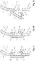
- the Figures 4a to 4c explain in schematic representations a method according to an optional embodiment for installing the trim component 10 in a vehicle interior, a functional element 26 being formed at the position at which the functional opening 24 is arranged.
- the paneling component is pressed in a predetermined angular range to the desired position in which the paneling component 10 is to be arranged in the vehicle interior.
- the angular range can be formed, for example, in a range from 0° to 45° relative to the surface normal of the functional opening or the surface spanned by the functional opening 24 .
- the in the Figures 4a to 4c The direction of movement shown is indicated by the arrows 100 .
- the unlocking element 18 comes into contact with the functional element 26 in such a way that the functional element 26 applies a force to the pressure surface 22 .
- the compressive force of the functional element 26 on the unlocking element 18 becomes so strong that the unlocking element 18 deforms the cover 14 .
- the deformation of the cover 14 includes, in particular, such a deformation of the unlocking element 18 that the latching cover 18a detaches from the trim component 10 .
- the self-releasing cover 14 detaches from the trim component 10 and releases the functional opening 24 when a functional element 26 is formed at the corresponding position. If no functional element 26 is formed at the appropriate point during assembly of the cladding component 10, the cover 14 is not unlocked and accordingly not removed from the cladding component 10, so that the functional opening 24 remains covered.
- figure 5 12 shows a vehicle 28 according to an optional embodiment, the depiction shown providing a view of the vehicle interior through the left rear door of the vehicle.
- the arrow 200 indicates the position at which the trim component 10 designed as a sill strip is arranged, which has a self-locking cover 14 .
- the self-locking cover 14 is only indicated schematically and highlighted in color for identification. In other embodiments, the self-locking cover 14 can be color-matched to the trim component and match in color with it. According to the embodiment shown, the self-locking cover is arranged in the footwell of the rear seat bench. If, according to another variant of the vehicle 28, an eyelet for a luggage net is desired and preassembled there, the self-releasing cover 14 is removed during assembly of the trim component 10 and the functional opening 24 is released for the eyelet.
Landscapes
- Engineering & Computer Science (AREA)
- Mechanical Engineering (AREA)
- Manufacturing & Machinery (AREA)
- Chemical & Material Sciences (AREA)
- Combustion & Propulsion (AREA)
- Transportation (AREA)
- Vehicle Interior And Exterior Ornaments, Soundproofing, And Insulation (AREA)
Abstract
Description
- Die vorliegende Erfindung betrifft eine selbstentriegelnde Abdeckung für eine Funktionsöffnung eines Verkleidungsbauteils, ein Verkleidungsbauteil, ein Fahrzeug, ein Verfahren zur Montage eines Verkleidungsbauteils und ein Verfahren zur Herstellung eines Fahrzeugs. Die Erfindung liegt insbesondere auf dem Gebiet der Fahrzeugtechnik, insbesondere der Fahrzeuginnenräume.
- Für manche Fahrzeuge ist es wünschenswert, an manchen Stellen im Fahrzeuginnenraum Funktionselemente bereitzustellen, welche durch die Verkleidung des Fahrzeuginnenraums hindurchragen müssen. Beispielsweise kann es sich bei solchen Funktionselementen um Ösen handeln, welche einerseits vom Fahrzeuginnenraum aus zugänglich sein müssen und andererseits mit der Fahrzeugkarosserie verbunden sein müssen. Beispielsweise kann eine solche Öse zur Befestigung eines Gepäcknetzes dienen, welches die gegebenenfalls im Gepäckraum des Fahrzeugs befindliche Ladung gegen ein Verrutschen und insbesondere gegen ein Eindringen in den Fahrgastraum sichert. Um das Bereitstellen solcher Funktionselemente zu ermöglichen, ist es erforderlich, entsprechende Funktionsöffnungen in der Verkleidung des Fahrzeuginnenraums bereitzustellen.
- Da jedoch solche Funktionselemente und die zugehörigen Funktionsöffnungnen in der Fahrzeugverkleidung nicht in jedem Fahrzeug gewünscht beziehungsweise benötigt sind, beispielsweise weil es sich dabei um ein optionales Zubehör handelt, welches je nach Kundenwunsch vorgesehen oder weggelassen wird, ist es herkömmlicherweise erforderlich, zumindest zwei verschiedene Varianten für die jeweiligen Verkleidungsbauteile vorzuhalten, nämlich eine Variante mit Funktionsöffnung und eine weitere Variante ohne Funktionsöffnung. Diese erforderliche Variantenvielfalt führt zu einem erhöhten Logistikaufwand und entsprechend zu erhöhten Produktionskosten.
- Alternativ zu der Bereitstellung verschiedener Varianten von Verkleidungsbauteilen sind im Stand der Technik auch solche Verkleidungsbauteile üblich, bei welchen die optional gewünschte Funktionsöffnung mit einem Deckel abgedeckt ist, der bei Bedarf im Rahmen der Montage des Verkleidungsbauteils entfernt werden kann, um die Funktionsöffnung freizugeben. Umgekehrt ist es auch möglich, den Deckel nur dann an der Montagelinie zu setzen, falls er benötigt wird. Allerdings verursacht die optional notwendige Entfernung des Deckels, sofern die Funktionsöffnung gewünscht ist, beziehungsweise das optional notwendige Anbringen des Deckels, falls die Funktionsöffnung nicht benötigt wird, einen weiteren erforderlichen Montageschritt, der ebenfalls den Aufwand und die Produktionskosten erhöht.
- Eine weitere denkbare Alternative, bei welcher bei Abwesenheit eines Funktionselements die dafür vorgesehene Funktionsöffnung offen und ungenutzt bleibt, ist zumeist aus ästhetischen Gründen abzulehnen, da dies für das optische Erscheinungsbild des Fahrzeuginnenraums nachteilig ist.
- Es ist daher die Aufgabe der Erfindung, eine Möglichkeit bereitzustellen, welche die optionale Bereitstellung einer Funktionsöffnung in einem Verkleidungsbauteil mit geringem Aufwand ermöglicht.
- Diese Aufgabe wird erfindungsgemäß gelöst durch eine selbstentriegelnde Abdeckung, ein Verkleidungsbauteil, ein Fahrzeug und ein Verfahren zur Montage eines Verkleidungsbauteils mit den Merkmalen der jeweiligen unabhängigen Ansprüche. Vorteilhafte Ausgestaltungen sind in den Unteransprüchen und in der Beschreibung angegeben.
- In einem ersten Aspekt betrifft die Erfindung eine selbstentriegelnde Abdeckung für eine Funktionsöffnung eines Verkleidungsbauteils eines Fahrzeuginnenraums. Die Abdeckung weist einen Deckel auf, welcher mit der Funktionsöffnung des Verkleidungsbauteils derart verrastbar ist, dass eine Vorderseite des Deckels die Funktionsöffnung zumindest teilweise bedeckt. Zudem weist die Abdeckung zumindest ein Entriegelungselement auf, welches an einer der Vorderseite des Deckels abgewandten Rückseite des Deckels angeordnet ist. Dabei ist die Abdeckung derart ausgebildet, dass das Entriegelungselements durch eine Krafteinwirkung auf das Entriegelungselement in Richtung des Deckels betätigbar ist und durch die Betätigung der Deckel verformbar und/oder verschiebbar und eine Verrastung des Deckels mit der Funktionsöffnung lösbar ist.
- In einem weiteren Aspekt betrifft die Erfindung ein Verkleidungsbauteil für einen Fahrzeuginnenraum. Das Verkleidungsbauteil umfasst eine Funktionsöffnung, welche derart ausgebildet ist, dass in der Funktionsöffnung in geöffnetem Zustand ein Funktionselement anordenbar ist, sowie eine selbstentriegelnde Abdeckung für die Funktionsöffnung. Die Abdeckung weist einen Deckel auf, welcher mit der Funktionsöffnung verrastet ist, dass eine Vorderseite des Deckels die Funktionsöffnung zumindest teilweise bedeckt. Zudem weist die Abdeckung zumindest ein Entriegelungselement auf, welches an einer der Vorderseite des Deckels abgewandten Rückseite des Deckels angeordnet ist. Dabei ist das Verkleidungsbauteil derart ausgebildet, dass durch eine Krafteinwirkung im Wesentlichen senkrecht zur Funktionsöffnung auf das Entriegelungselement der Deckel verschiebbar und/oder verformbar und die Verrastung des Deckels mit der Funktionsöffnung lösbar ist.
- In einem weiteren Aspekt betrifft die Erfindung ein Fahrzeug mit einer erfindungsgemäßen selbstentriegelnden Abdeckung und/oder mit einem erfindungsgemäßen Verkleidungsbauteil.
- In einem weiteren Aspekt betrifft die Erfindung ein Verfahren zur Montage eines Verkleidungsbauteils mit einer Funktionsöffnung und einer in der Funktionsöffnung verrasteten, selbstentriegelnden Abdeckung in einem Fahrzeug oder an einem Fahrzeugbauteil. Das Verfahren umfasst ein Bereitstellen eines Funktionselements im Fahrzeug bzw. am Fahrzeugbauteil am Bestimmungsort der Funktionsöffnung des Verkleidungsbauteils. Außerdem umfasst das Verfahren ein Anordnen des Verkleidungsbauteils am Bestimmungsort im Fahrzeug bzw. am Fahrzeugbauteil derart, dass durch eine Kraftausübung im Wesentlichen senkrecht zur Funktionsöffnung mittels des Funktionselements die selbstentriegelnde Abdeckung betätigt wird und dadurch die in der Funktionsöffnung verrastete, selbstentriegelnde Abdeckung aus der Funktionsöffnung gelöst wird.
- In einem weiteren Aspekt betrifft die Erfindung ein Verfahren zur Herstellung eines Fahrzeugs, umfassend ein Verfahren zur Montage eines Verkleidungsbauteils an einem Fahrzeugbauteil des Fahrzeugs gemäß einem Aspekt der Erfindung.
- Eine selbstentriegelnde Abdeckung ist dabei eine Abdeckung, welche sich bei der Montage selbstständig von dem Verkleidungsbauteil trennt und die Funktionsöffnung freigibt, ohne dass dazu ein separater Arbeitsschritt bei der Montage erforderlich ist.
- Eine Funktionsöffnung ist dabei eine Öffnung bzw. Ausnehmung in dem Verkleidungsbauteil, durch welche ein Funktionselement hindurchragen oder hindurchtreten kann und/oder mittels welcher ein unter dem Verkleidungsbauteil angeordnetes Funktionselement aus dem Fahrzeuginnenraum zugänglich ist.
- Ein Verkleidungsbauteil ist dabei ein Bauteil der Verkleidung des Fahrzeuginnenraums. Insbesondere kann das Verkleidungsbauteil als Einstiegsleiste, Armaturenbrett, Handschuhfach, Mittelkonsole, Fahrzeuginnenraumboden, Dachhimmel, Türverkleidung und/oder Gepäckraumverkleidung oder als Teil eines dieser Elemente ausgebildet sein.
- Dass der Deckel mit der Funktionsöffnung des Verkleidungsbauteils verrastbar ist, bedeutet, dass der Deckel kraftschlüssig und/oder formschlüssig mit dem Verkleidungsbauteil verbindbar ist. Mit anderen Worten kann der Deckel in der Funktionsöffnung des Verkleidungsbauteils verklemmt sein.
- Dass die Krafteinwirkung zur Betätigung des Entriegelungselement in Richtung des Deckels erfolgt bedeutet dabei, dass die Krafteinwirkung zumindest teilweise und optional vollständig senkrecht zur Vorderseite des Deckels und/oder senkrecht zur Rückseite des Deckels erfolgt, d.h. dass die Krafteinwirkung nicht vollständig parallel zur Vorderseite und/oder Rückseite des Deckels erfolgt. Mit anderen Worten erfolgt die Krafteinwirkung auf das Entriegelungselement von hinten, d.h. von der dem Deckel abgewandten Seite, in Richtung des Deckels.
- Dass die Krafteinwirkung im Wesentlichen senkrecht zur Funktionsöffnung auf das Entriegelungselement wirkt bedeutet dabei, dass die Krafteinwirkung nicht vollständig parallel zur Funktionsöffnung erfolgt, sondern eine senkrechte Vektorkomponente der Kraft relativ zur Fläche der Funktionsöffnung aufweist. Optional liegt der Winkelbereich, in dem die Krafteinwirkung auf das Entriegelungselement erfolgt, in einem Winkelbereich von 0° bis 45° um die Flächennormale der Fläche der Funktionsöffnung.
- Die Erfindung bietet den Vorteil, dass nur eine Variante von Verkleidungsbauteilen bereitgestellt werden müssen, wenngleich dieses in manchen Ausführungen mit offengelegter Funktionsöffnung und in anderen Varianten mit abgedeckter Funktionsöffnung benötigt wird. Dadurch werden der Logistikaufwand und entsprechend die Produktionskosten verringert.
- Ferner bietet die Erfindung den Vorteil, dass bei solchen Varianten von Fahrzeugen, an welchen die Funktionsöffnung für ein optionales Funktionselement gewünscht ist und bei denen das Funktionselement bereits vor der Montage des Verkleidungsbauteils montiert ist, die selbstentriegelnde Abdeckung bei der Montage des Verkleidungsbauteils selbstständig entfernt wird. Dies bietet den Vorteil, dass für die Entfernung des Deckels bzw. für die Freilegung der Funktionsöffnung kein zusätzlicher Arbeitsschritt erforderlich ist. Vielmehr bietet die Erfindung den Vorteil, dass die Entfernung der Abdeckung bzw. das Freilegen der Funktionsöffnung bei der regulären Montage des Verkleidungsbauteils, d.h. beim Anordnen des Verkleidungsbauteils am bestimmungsgemäßen Ort im Fahrzeuginnenraum bzw. am Fahrzeugbauteil, selbstständig erfolgt, ohne dass für den Monteur dafür ein zusätzlicher Aufwand entsteht.
- Optional weist das Entriegelungselement an der Rückseite des Deckels eine Druckfläche auf, welche mit der zur Entriegelung der Verrastung erforderlichen Krafteinwirkung beaufschlagbar ist. Die Druckfläche bietet den Vorteil, die bei der Montage durch das Funktionselement bewirkte Krafteinwirkung aufzunehmen und an die gewünschte Stelle der Abdeckung zu leiten.
- Optional ist die Druckfläche in einem spitzen Winkel zur Vorderseite des Deckels angeordnet. Dies bietet den Vorteil, dass die senkrecht in Richtung des Deckels auf das Entriegelungselement einwirkende Kraft zumindest teilweise umgelenkt werden kann, um auch eine Kraftkomponente parallel zum Deckel bereitzustellen. Dies kann für die Entriegelung der Verrastung vorteilhaft sein. Insbesondere kann die Abdeckung, bzw. das Entriegelungselement bzw. die Druckfläche derart ausgebildet sein, dass eine Krafteinwirkung durch das Funktionselement auf die Druckfläche eine Hebelwirkung auf den Deckel und/oder auf eine Rastausprägung des Entriegelungselements bewirkt, welche zur Entriegelung der Verrastung mit dem Verkleidungsbauteil führt.
- Optional ist die Abdeckung derart ausgebildet, dass die Verformung des Deckels und/oder die Verschiebung des Deckels durch die Krafteinwirkung auf das Entriegelungselement zumindest teilweise senkrecht zur Richtung der Krafteinwirkung erfolgt. Dies bietet den Vorteil, dass auch Kraftkomponenten für die Entriegelung der Verrastung erzeugt und/oder genutzt werden können, die senkrecht zur ursprünglichen Krafteinwirkung, welche durch ein Drücken des Verkleidungsbauteils auf das Funktionselement entsteht, und auf diese Weise eine größere Flexibilität für Mechanismen zur Entriegelung der Verrastung erzielt wird.
- Optional ist die selbstentriegelnde Abdeckung im montierten Zustand des Verkleidungsbauteils bei in der Funktionsöffnung angeordnetem Funktionselement von der Funktionsöffnung des Verkleidungsbauteils gelöst, insbesondere irreversibel gelöst.
- Bei der besonders bevorzugten irreversiblen Ablösung der selbstentriegelnden Abdeckung ist mit anderen Worten in dem genannten Zustand die Abdeckung nicht wieder an der Funktionsöffnung anbringbar. Dies kann beispielsweise dadurch bedingt sein, dass sich das Funktionselement durch die Funktionsöffnung hindurch erstreckt und somit eine Anordnung der Abdeckung an der Funktionsöffnung nicht mehr ermöglicht. Optional kann dies auch dadurch bedingt sein, dass ein Verrasten in verbautem Zustand des Verkleidungsbauteils nicht mehr möglich ist, selbst wenn sich kein Funktionselement durch die Funktionsöffnung erstreckt. Dies bietet den Vorteil, dass ein nicht vorgesehenes Wiederverschließen der Funktionsöffnung mittels einer Abdeckung verhindert werden kann.
- Optional ist das Verkleidungsbauteil als eine Einstiegsleiste ausgebildet ist. Dies bietet den Vorteil, dass insbesondere in der Einstiegsleiste das Anbringen von abgedeckten oder nichtabgedeckten Funktionsöffnungen, je nach Modellvariante des Fahrzeugs, erreicht werden kann. Beispielsweise kann das Funktionselement als eine Öse für ein Gepäcknetz ausgebildet sein oder eine solche umfassen. Die Anbringung von Ösen, etwa zur optionalen Befestigung eines Gepäcknetzes zur Trennung des Gepäckraums von Fahrgastraum, kann beispielsweise je nach Modellvariante des Fahrzeugs gewünscht oder unerwünscht sein, sodass entsprechend Einstiegsleisten mit und ohne entsprechende Funktionsöffnungen realisierbar sein müssen.
- Optional wird der Deckel lediglich durch mechanische Kräfte aufgrund der Verrastung an dem Verkleidungsbauteil gehalten. Optional können der Deckel und/oder das Verkleidungsbauteil im Bereich der Funktionsöffnung entsprechende Rastnasen aufweisen. Dies bietet den Vorteil, dass die Anbringung der Abdeckung an der Funktionsöffnung ohne die Verwendung von separaten Befestigungsmitteln und/oder Haftmitteln erfolgen kann und entsprechend beim Entriegeln der Verrastung kein Entfernen solcher Befestigungsmittel und/oder Haftmittel erforderlich ist.
- Optional ist die Abdeckung einstückig ausgebildet. Beispielsweise sind der Deckel und das Entriegelungselement als ein einziges Formstück ausgebildet. Optional ist die Abdeckung zumindest teilweise aus Kunststoff ausgebildet. Dies bietet den Vorteil, dass die Herstellung der Abdeckung besonders einfach und kostengünstig ausgestaltet werden kann.
- Optional sind die selbstentriegelnde Abdeckung und das Verkleidungsbauteil als separate Bauteile ausgebildet. Dies bietet den Vorteil, dass eine saubere Trennung der Abdeckung von dem Verkleidungsbauteil beim Entriegeln der Verrastung erzielt werden kann. Gemäß anderen Ausführungsformen können jedoch die Abdeckung und das Verkleidungsbauteil einstückig ausgebildet sein.
- Optional schließt die Vorderseite des Deckels zumindest teilweise im Wesentlichen bündig mit einer Außenfläche des Verkleidungsbauteils ab. Dies bedeutet dabei, dass die Vorderseite des Deckels und die den Deckel umgebende Außenfläche des Verkleidungsbauteils zumindest teilweise eine kontinuierliche Fläche bilden. Beispielsweise kann ein Rand des Deckels bündig mit der Außenfläche des Verkleidungsbauteils abschließen, sodass an der umlaufenden Kontur der Funktionsöffnung abgesehen von einer minimalen Fuge eine ebene Fläche durch die Außenfläche des Verkleidungsbauteils und den Deckel gebildet wird. Optional kann die Abdeckung derart ausgebildet sein, dass die Vorderseite des Deckels vollständig bündig mit der Außenfläche des Deckels abschließt und dabei der Deckel und die Außenfläche vollständig eine ebene Fläche bzw. Kontur bilden. Alternativ kann jedoch der Deckel auch eine Ausbeulung und/oder Einkerbung aufweisen, sodass dieser mit der Außenfläche keine vollständig ebene Fläche bzw. Kontur bildet. Gemäß anderen optionalen Ausführungsformen kann die Abdeckung Rastnasen aufweisen, welche um das die Funktionsöffnung begrenzende Verkleidungsbauteil herum anordenbar sind.
- Die Montage des Verkleidungsbauteils kann dabei einen Teil eines Verfahrens zur Herstellung oder Reparatur eines Fahrzeugs bilden.
- Ein Fahrzeug kann dabei beispielsweise in Form eines Landfahrzeugs, Luftfahrzeugs oder Wasserfahrzeugs ausgebildet sein. Ein Landfahrzeug kann beispielsweise als ein Straßenfahrzeug oder als ein schienengebundenes Fahrzeug ausgebildet sein. Insbesondere kann ein Fahrzeug als ein Kraftfahrzeug vorliegen, wie etwa als Personenkraftwagen, Lastkraftwagen, Autobus oder Motorrad.
- Die oben genannten und im Folgenden erläuterten Merkmale und Ausführungsformen sind dabei nicht nur als in den jeweils explizit genannten Kombinationen offenbart anzusehen, sondern sind auch in anderen technisch sinnhaften Kombinationen und Ausführungsformen vom Offenbarungsgehalt umfasst.
- Weitere Einzelheiten und Vorteile der Erfindung sollen nun anhand der folgenden Beispiele und bevorzugten Ausführungsformen mit Bezug auf die Figuren näher erläutert werden.
- Es zeigen:
- Fig. 1A und 1B
- ein Verkleidungsbauteil gemäß einer optionalen Ausführungsform;
- Fig. 2A und 2B
- eine selbstentriegelnde Abdeckung gemäß einer optionalen Ausführungsform;
- Fig. 3
- ein montiertes Verkleidungsbauteil gemäß einer optionalen Ausführungsform mit sich hindurch erstreckendem Funktionselement;
- Fig. 4a, 4b, 4c
- erläuternde Darstellungen zu einem optionalen Montageverfahren für ein Verkleidungsbauteil;
- Fig. 5
- ein Fahrzeug gemäß einer optionalen Ausführungsform.
- In den folgenden Figuren werden gleiche oder ähnliche Elemente in den verschiedenen Ausführungsformen der Einfachheit halber mit gleichen Bezugszeichen bezeichnet.
-
Figur 1A zeigt ein Verkleidungsbauteil 10 gemäß einer optionalen Ausführungsform. Gemäß der gezeigten Ausführungform ist das Verkleidungsbauteil 10 als eine Einstiegsleiste für den Innenraum eines Fahrzeugs ausgebildet. Im unteren Bereich weist das Verkleidungsbauteil 10 eine Einbuchtung 12 auf, in welcher eine Funktionsöffnung ausgebildet ist, die mit einer selbstentriegelnden Abdeckung 14 abgedeckt ist und daher in der gezeigten Ansicht nicht zu erkennen ist. Dabei ist lediglich die Vorderseite der Abdeckung zu erkennen, welche durch die Vorderseite 16a eines Deckels 16 gebildet wird. - Die Einbuchtung 12 mit der Abdeckung 14 ist in
Figur 1B in einer vergrößerten Darstellung gezeigt. Dabei ist erkennbar, dass die Abdeckung 14 die Funktionsöffnung in dem Verkleidungsbauteil vollständig ausfüllt und abdeckt, sodass die Funktionsöffnung nicht zu erkennen ist. Die Abdeckung 12 dient dazu, die Funktionsöffnung für solche Modellvarianten des Fahrzeugs, in welches die Seitenleiste eingebaut werden soll, verschlossen zu halten, in denen an der jeweiligen Position kein Funktionselement und entsprechend auch keine Funktionsöffnung bereitgestellt werden soll. Wird das Verkleidungsbauteil 10 jedoch in anderen Modellvarianten verwendet, in welchen ein Funktionselement an der entsprechenden Stelle ausgebildet ist, wird bei der Montage des Verkleidungsbauteils 10 die Abdeckung 14 selbstständig entriegelt, sodass die Funktionsöffnung und das Funktionselement freigegeben werden und die Abdeckung 14 entfernt wird. Gemäß anderen optionalen Ausführungsformen ist die Abdeckung nicht in einer Einbuchtung des Verkleidungsbauteils 10 angeordnet. -
Figur 2A zeigt die selbstentriegelnde Abdeckung 14 in Alleinstellung von der Rückseite betrachtet. An der Rückseite 16b der Abdeckung 14 bzw. des Deckels 16 ist ein Entriegelungselement 18 ausgebildet, sowie mehrere Rastnasen 20, wobei auch das Verriegelungselement 18 eine Rastausprägung 18a aufweist. Mittels der Rastnasen 20 und der Rastausprägung 18a des Entriegelungselements 18 kann die Abdeckung 14 mit einer dafür vorgesehenen Funktionsöffnung des Verkleidungsbauteils 10 verrastet werden, sodass die Abdeckung 14 formschlüssig und/oder kraftschlüssig mit dem Verkleidungsbauteil 10 verbunden ist. Des Weiteren weist das Entriegelungselement 18 eine Druckfläche 22 auf, welche sich in einem spitzen Winkel relativ zur Rückseite 16b und zur Vorderseite des Deckels 16 bzw. relativ zur Vorderseite 16a des Deckels 16 erstreckt. Das Entriegelungselement 14 und insbesondere die Druckfläche 22 sind dazu ausgebildet, eine Kraft aufzunehmen, welche beim Montieren des Verkleidungsbauteils 10 in ein Fahrzeug auf das Entriegelungselement einwirkt, wenn ein Funktionselement an der Stelle ausgebildet ist, an welcher die Funktionsöffnung des Verkleidungsbauteils 10 angeordnet werden soll, sodass sich das Funktionselement durch die Funktionsöffnung hindurch erstreckt. Durch die Krafteinwirkung wird sodann die Verriegelung der Abdeckung 14 mit der Funktionsöffnung gelöst, wie weiter unten noch im Detail beschrieben wird. -
Figur 2B zeigt einen Ausschnitt des Verkleidungsbauteils 10 von dessen Rückseite, welche auch die Rückseite der Abdeckung 14 bzw. die Rückseite 16b des Deckels 16 zu erkennen gibt. Die Abdeckung 14 ist dabei mittels der Rastnasen 20 und der Rastausprägung 18a des Entriegelungselements 18 mit der Funktionsöffnung 24 verrastet, sodass die Abdeckung 14 in der Funktionsöffnung 24 gehalten wird und diese verschließt bzw. abdeckt. -
Figur 3 zeigt das als Einstiegsleiste ausgebildete Verkleidungsbauteil 10 gemäß der in denFiguren 1A und1B gezeigten Ausführungsform erneut von der Vorderseite, jedoch in einem Zustand, in dem ein Funktionselement 26 an der Stelle der Funktionsöffnung ausgebildet ist und die Abdeckung 14 entsprechend bei der Montage des Verkleidungsbauteils 10 selbstständig aus der Verrastung mit der Funktionsöffnung 24 gelöst und entfernt wurde. Dadurch, dass die Abdeckung 14 die Funktionsöffnung 24 nicht mehr bedeckt, ist die Funktionsöffnung 24 zu erkennen, sowie das Funktionselement 26, welches sich durch die Funktionsöffnung 24 des Verkleidungsbauteils 10 hindurch erstreckt. - Das Funktionselement 26 ist dabei als eine Öse ausgebildet. Gemäß der gezeigten optionalen Ausführungsform handelt es sich dabei um eine Öse, welche mit der Fahrzeugkarosserie (nicht gezeigt) verbunden ist und in welcher ein Gepäcknetz (nicht gezeigt) befestigt werden kann. Dadurch, dass die Öse einerseits an der unter bzw. hinter dem Verkleidungsbauteil befindlichen Fahrzeugkarosserie befestigt werden muss und andererseits vom Fahrzeuginnenraum zur Befestigung des Gepäcknetzes zugänglich sein muss, ist es erforderlich, die Funktionsöffnung 24 bereitzustellen, durch welche sich das Funktionselement 26 hindurch erstrecken kann. Die Einbuchtung 12 ist dabei gemäß der gezeigten optionalen Ausführungsform derart ausgebildet, dass diese das Funktionselement 24 einbettet, sodass das Funktionselement 24 kein freistehendes Hindernis im Fahrzeuginnenraum darstellt.
- Die
Figuren 4a bis 4c erläutern in schematischen Darstellungen ein Verfahren gemäß einer optionalen Ausführungsform zur Montage des Verkleidungsbauteils 10 in einem Fahrzeuginnenraum, wobei an der Position, an welcher die Funktionsöffnung 24 angeordnet wird, ein Funktionselement 26 ausgebildet ist. - Dabei wird das Verkleidungsbauteil in einem vorbestimmten Winkelbereich an die gewünschte Position gedrückt, in welcher das Verkleidungsbauteil 10 im Fahrzeuginnenraum angeordnet werden soll. Der Winkelbereich kann beispielsweise in einem Bereich von 0° bis 45° relativ zur Flächennormale der Funktionsöffnung bzw. der von der Funktionsöffnung 24 aufgespannten Fläche ausgebildet sein. Die in den
Figuren 4a bis 4c dargestellte Bewegungsrichtung ist mit den Pfeilen 100 angedeutet. - Bei der Bewegung des Verkleidungsbauteils 10 in die bestimmungsgemäße Position bei der Montage kommt das Entriegelungselement 18 derart mit dem Funktionselement 26 in Kontakt, dass das Funktionselement 26 die Druckfläche 22 mit einer Kraft beaufschlagt. Wird die Bewegung des Verkleidungsbauteils 10 bei der Montage in Richtung der bestimmungsgemäßen Position fortgesetzt, wird die Druckkraft des Funktionselements 26 auf das Entriegelungselement 18 derart stark, dass das Entriegelungselement 18 die Abdeckung 14 verformt. Gemäß der gezeigten Ausführungsform umfasst die Verformung der Abdeckung 14 insbesondere ein derartiges Verformen des Entriegelungselements 18, dass sich die Rastabdeckung 18a von dem Verkleidungsbauteil 10 löst. In
Figur 4c ist die Verformung durch die Krafteinwirkung über das Funktionselement derart stark ausgeprägt, dass die Rastausprägung 18a die Verrastung löst und entsprechend die Abdeckung 14 von der Funktionsöffnung 24 freigibt und entsprechend die Funktionsöffnung 24 freilegt. Die dabei auf das Entriegelungselement 18 einwirkende Kraft beschränkt sich bei der gezeigten Ausführungsform auf jene Kraft, mit der bei der Montage des Verkleidungsbauteils 10 das Verkleidungsbauteil 10 in die gewünschte Position und entsprechend das Entriegelungselement auf das Funktionselement 26 gedrückt wird. Beispielsweise kann dieser Montageschritt durch einen Monteur und/oder einen Roboter durchgeführt werden. - Auf diese Weise löst sich bei der Montage des Verkleidungsbauteils die selbstentriegelnde Abdeckung 14 vom Verkleidungsbauteil 10 und gibt die Funktionsöffnung 24 frei, wenn ein Funktionselement 26 an der entsprechenden Position ausgebildet ist. Sofern kein Funktionselement 26 an der entsprechenden Stelle während der Montage des Verkleidungsbauteils 10 ausgebildet ist, wird die Abdeckung 14 nicht entriegelt und entsprechend auch nicht von dem Verkleidungsbauteil 10 entfernt, sodass die Funktionsöffnung 24 abgedeckt beleibt.
-
Figur 5 zeigt ein Fahrzeug 28 gemäß einer optionalen Ausführungsform, wobei die gezeigte Darstellung eine Ansicht des Fahrzeuginnenraums durch die linke hintere Türe des Fahrzeugs bietet. Der Pfeil 200 kennzeichnet dabei die Position, an welcher das als Einstiegsleiste ausgebildete Verkleidungsbauteil 10 angeordnet ist, welches eine selbstentriegelnde Abdeckung 14 aufweist. Die selbstentriegelnde Abdeckung 14 ist dabei lediglich schematisch angedeutet und zur Kenntlichmachung farblich hervorgehoben. In andern Ausführungsformen kann die selbstentriegelnde Abdeckung 14 farblich an das Verkleidungsbauteil angepasst sein und farblich mit diesem übereinstimmen. Die selbstentriegelnde Abdeckung ist gemäß der gezeigten Ausführungsform im Fußraum der Rücksitzbank angeordnet. Sofern gemäß einer anderen Variante des Fahrzeugs 28 dort eine Öse für ein Gepäcknetz gewünscht und vormontiert ist, wird bei der Montage des Verkleidungsbauteils 10 die selbstentriegelnde Abdeckung 14 entfernt und die Funktionsöffnung 24 für die Öse freigegeben. -
- 10
- Verkleidungsbauteil
- 12
- Einbuchtung
- 14
- selbstentriegelnde Abdeckung
- 16
- Deckel
- 16a
- Vorderseite des Deckels
- 16b
- Rückseite des Deckels
- 18
- Entriegelungselement
- 18a
- Rastausprägung des Entriegelungselements
- 20
- Rastnase
- 22
- Druckfläche
- 24
- Funktionsöffnung
- 26
- Funktionselement
- 28
- Fahrzeug
- 100
- Bewegungsrichtung des Verkleidungsbauteils bei der Montage
- 200
- Pfeil zur Kenntlichmachung der Position der selbstentriegelnden Abdeckung
Claims (11)
- Selbstentriegelnde Abdeckung (14) für eine Funktionsöffnung (24) eines Verkleidungsbauteils (10) eines Fahrzeuginnenraums, wobei die Abdeckung aufweist:- einen Deckel (16), welcher mit der Funktionsöffnung (24) des Verkleidungsbauteils (10) derart verrastbar ist, dass eine Vorderseite (16a) des Deckels (16) die Funktionsöffnung (24) zumindest teilweise bedeckt;- zumindest ein Entriegelungselement (18), welches an einer der Vorderseite (16a) des Deckels (16) abgewandten Rückseite (16b) des Deckels (16) angeordnet ist;wobei die Abdeckung (14) derart ausgebildet ist, dass das Entriegelungselement (18) durch eine Krafteinwirkung auf das Entriegelungselement (18) in Richtung des Deckels (16) betätigbar ist und durch die Betätigung der Deckel (16) verformbar und/oder verschiebbar und eine Verrastung des Deckels (16) mit der Funktionsöffnung (24) lösbar ist.
- Abdeckung (14) gemäß dem vorhergehenden Anspruch, wobei das Entriegelungselement (18) an der Rückseite (16b) des Deckels (16) eine Druckfläche (22) aufweist, welche mit der zur Entriegelung der Verrastung erforderlichen Krafteinwirkung beaufschlagbar ist.
- Abdeckung (14) gemäß einem der vorhergehenden Ansprüche, wobei die Druckfläche (22) in einem spitzen Winkel zur Vorderseite (16a) des Deckels (16) angeordnet ist.
- Abdeckung (14) gemäß einem der vorhergehenden Ansprüche, wobei die Abdeckung (14) derart ausgebildet ist, dass die Verformung des Deckels (16) und/oder die Verschiebung des Deckels (16) durch eine Krafteinwirkung auf das Entriegelungselement (18) zumindest teilweise senkrecht zur Richtung der Krafteinwirkung erfolgt.
- Verkleidungsbauteil (10) für einen Fahrzeuginnenraum, das Verkleidungsbauteil (10) umfassend:- eine Funktionsöffnung (24), welche derart ausgebildet ist, dass in der Funktionsöffnung (24) in geöffnetem Zustand ein Funktionselement (26) anordenbar ist;- eine selbstentriegelnde Abdeckung (14) für die Funktionsöffnung (24), wobei die Abdeckung (14) einen Deckel (16) aufweist, welcher mit der Funktionsöffnung (24) verrastet ist und eine Vorderseite (16a) des Deckels (16) die Funktionsöffnung (24) zumindest teilweise bedeckt, und wobei die Abdeckung (14) zumindest ein Entriegelungselement (18) aufweist, welches an einer der Vorderseite (16a) des Deckels (16) abgewandten Rückseite (16b) des Deckels (16) angeordnet ist;wobei das Verkleidungsbauteil (10) derart ausgebildet ist, dass durch eine Krafteinwirkung im Wesentlichen senkrecht zur Funktionsöffnung (24) auf das Entriegelungselement (18) der Deckel (16) verschiebbar und/oder verformbar und die Verrastung des Deckels (16) mit der Funktionsöffnung (24) lösbar ist.
- Verkleidungsbauteil (10) gemäß Anspruch 5, wobei die selbstentriegelnde Abdeckung (14) in montiertem Zustand des Verkleidungsbauteils (10) bei in der Funktionsöffnung (24) angeordnetem Funktionselement (26) von der Funktionsöffnung (24) des Verkleidungsbauteils (10) gelöst ist, insbesondere irreversibel gelöst ist.
- Verkleidungsbauteil (10) gemäß einem der Ansprüche 5 bis 6, wobei das Verkleidungsbauteil (10) als eine Einstiegsleiste ausgebildet ist.
- Fahrzeug (28) mit einer selbstentriegelnden Abdeckung (14) gemäß einem der Ansprüche 1 bis 4 und/oder mit einem Verkleidungsbauteil (10) gemäß einem der Ansprüche 5 bis 7.
- Verfahren zur Montage eines Verkleidungsbauteils (10), das eine Funktionsöffnung (24) und eine in der Funktionsöffnung (24) verrastete selbstentriegelnde Abdeckung (14) aufweist, an einem Fahrzeugbauteil, wobei das Verfahren die folgenden Schritte umfasst:- Bereitstellen eines Funktionselements (26) am Fahrzeugbauteil am Bestimmungsort der Funktionsöffnung (24) des Verkleidungsbauteils (10);- Anordnen des Verkleidungsbauteils (10) am Bestimmungsort am Fahrzeugbauteil derart, dass durch eine Kraftausübung im Wesentlichen senkrecht zur Funktionsöffnung (24) mittels des Funktionselements (26) die selbstentriegelnde Abdeckung betätigt wird und dadurch die in der Funktionsöffnung (24) verrastete, selbstentriegelnde Abdeckung (14) aus der Funktionsöffnung (24) gelöst wird.
- Verfahren gemäß Anspruch 9, wobei das Funktionselement (26) als eine Öse für ein Gepäcknetz ausgebildet ist oder eine solche umfasst.
- Verfahren zur Herstellung eines Fahrzeugs (28), umfassend ein Verfahren zur Montage eines Verkleidungsbauteils (10) an einem Fahrzeugbauteil des Fahrzeugs gemäß einem der Ansprüche 9 bis 10.
Priority Applications (1)
| Application Number | Priority Date | Filing Date | Title |
|---|---|---|---|
| EP23169350.8A EP4219245B1 (de) | 2020-12-22 | 2021-12-13 | Selbstentriegelungssystem, umfassend eine selbstentriegelnde abdeckung |
Applications Claiming Priority (1)
| Application Number | Priority Date | Filing Date | Title |
|---|---|---|---|
| DE102020216446.0A DE102020216446A1 (de) | 2020-12-22 | 2020-12-22 | Selbstentriegelnde Abdeckung, Verkleidungsbauteil und Verfahren zur Montage eines Verkleidungsbauteils |
Related Child Applications (2)
| Application Number | Title | Priority Date | Filing Date |
|---|---|---|---|
| EP23169350.8A Division EP4219245B1 (de) | 2020-12-22 | 2021-12-13 | Selbstentriegelungssystem, umfassend eine selbstentriegelnde abdeckung |
| EP23169350.8A Division-Into EP4219245B1 (de) | 2020-12-22 | 2021-12-13 | Selbstentriegelungssystem, umfassend eine selbstentriegelnde abdeckung |
Publications (3)
| Publication Number | Publication Date |
|---|---|
| EP4019336A2 true EP4019336A2 (de) | 2022-06-29 |
| EP4019336A3 EP4019336A3 (de) | 2022-10-26 |
| EP4019336B1 EP4019336B1 (de) | 2023-11-01 |
Family
ID=78844678
Family Applications (2)
| Application Number | Title | Priority Date | Filing Date |
|---|---|---|---|
| EP21213972.9A Active EP4019336B1 (de) | 2020-12-22 | 2021-12-13 | Selbstentriegelnde abdeckung, verkleidungsbauteil und verfahren zur montage eines verkleidungsbauteils |
| EP23169350.8A Active EP4219245B1 (de) | 2020-12-22 | 2021-12-13 | Selbstentriegelungssystem, umfassend eine selbstentriegelnde abdeckung |
Family Applications After (1)
| Application Number | Title | Priority Date | Filing Date |
|---|---|---|---|
| EP23169350.8A Active EP4219245B1 (de) | 2020-12-22 | 2021-12-13 | Selbstentriegelungssystem, umfassend eine selbstentriegelnde abdeckung |
Country Status (2)
| Country | Link |
|---|---|
| EP (2) | EP4019336B1 (de) |
| DE (1) | DE102020216446A1 (de) |
Family Cites Families (10)
| Publication number | Priority date | Publication date | Assignee | Title |
|---|---|---|---|---|
| US2241109A (en) * | 1940-01-12 | 1941-05-06 | Andrew Hoffman | Door lock |
| US4094436A (en) * | 1975-01-22 | 1978-06-13 | Trw Inc. | Aperture plug |
| DE9012651U1 (de) * | 1990-09-05 | 1990-11-29 | Adam Opel AG, 6090 Rüsselsheim | Vorrichtung zur Montage der Innenraumverkleidung von Kraftfahrzeugen |
| US6691468B2 (en) * | 2001-11-19 | 2004-02-17 | Sika Automotive | Orifice sealing physical barrier |
| EP1327564B1 (de) * | 2002-01-11 | 2005-12-21 | Toyoda Gosei Co., Ltd. | Knieschutz-Airbagvorrichtung |
| JP4497193B2 (ja) | 2007-11-09 | 2010-07-07 | ソニー株式会社 | カメラ取り付け構造、カメラ取り付け方法および車両の外装パネル部品 |
| US20090179458A1 (en) * | 2008-01-11 | 2009-07-16 | Toyota Motor Engineering & Manufacturing North America, Inc. | Automotive panel assembly |
| US10343611B2 (en) * | 2013-10-08 | 2019-07-09 | Honda Motor Co., Ltd. | Vehicle interior lid for covering interior component airbag attachment |
| DE102016014791A1 (de) * | 2016-12-10 | 2018-06-14 | GM Global Technology Operations LLC (n. d. Ges. d. Staates Delaware) | Kofferraumanordnung für ein Fahrzeug, Verfahren zur Sicherung eines Ladebodens einer Kofferraumanordnung gegen eine Entnahme aus einem Kofferraum der Kofferraumanordnung und Fahrzeug mit der Kofferraumanordnung |
| JP7037998B2 (ja) | 2018-04-19 | 2022-03-17 | 本田技研工業株式会社 | 輸送機器 |
-
2020
- 2020-12-22 DE DE102020216446.0A patent/DE102020216446A1/de not_active Withdrawn
-
2021
- 2021-12-13 EP EP21213972.9A patent/EP4019336B1/de active Active
- 2021-12-13 EP EP23169350.8A patent/EP4219245B1/de active Active
Also Published As
| Publication number | Publication date |
|---|---|
| DE102020216446A1 (de) | 2022-06-23 |
| EP4219245B1 (de) | 2025-02-12 |
| EP4219245A1 (de) | 2023-08-02 |
| EP4019336B1 (de) | 2023-11-01 |
| EP4019336A3 (de) | 2022-10-26 |
Similar Documents
| Publication | Publication Date | Title |
|---|---|---|
| DE102017130884B4 (de) | Luftfahrzeug und Verfahren zum Herstellen eines Luftfahrzeugs | |
| EP1088746A2 (de) | Fahrzeugdachmodul mit integrierter Schiebedacheinheit | |
| DE102008021265A1 (de) | Kraftfahrzeug mit A-Säule und in dieser gelagertem Airbag | |
| EP3650290B1 (de) | Gassackmodul, verfahren zu dessen montage sowie lenkungsbaugruppe mit einem solchen gassackmodul | |
| EP1651458A1 (de) | Kraftfahrzeugtür | |
| DE102019110083A1 (de) | Scheibenwischanlage für einen Kraftwagen | |
| DE102024129354A1 (de) | Anordnung zum bereitstellen einer befestigungsmöglichkeit für eine fahrzeugkomponente | |
| EP2492123B1 (de) | Fensterelement für eine Seitentür, insbesondere eine hintere Seitentür, eines Kraftwagens | |
| DE102015012874A1 (de) | Luftleitvorrichtung für einen Personenkraftwagen | |
| DE10103402B4 (de) | Außenrückblickspiegel eines Kraftfahrzeugs | |
| DE102017107055A1 (de) | Gleitverbindungsapplikation | |
| DE102020133889B4 (de) | Kraftfahrzeug | |
| EP4219245B1 (de) | Selbstentriegelungssystem, umfassend eine selbstentriegelnde abdeckung | |
| DE102010051038A1 (de) | Verfahren zur Montage eines Frontendmoduls | |
| DE102008062634A1 (de) | Befestigungseinrichtung für eine Lenksäule | |
| DE102012018293A1 (de) | Folie zur Abtrennung von einem Nassbereich zu einemTrockenbereich eines Türkastens einer Fahrzeugtür | |
| DE60014229T2 (de) | Einrichtung zur Montage und Befestigung eines Verkleidungs- oder Abdeckelements | |
| EP2305518A1 (de) | Vorrichtung für die Befestigung einer Stoßfängerverkleidung | |
| EP3250420B1 (de) | Gassackanordnung für ein kraftfahrzeug | |
| DE102008062899A1 (de) | Fahrzeugtür, insbesondere Fahrzeugseitentür | |
| WO2004110799A1 (de) | Kraftfahrzeugtür | |
| EP3501900B1 (de) | Innenmodul für einen laderaum eines fahrzeuges, laderaumverkleidung sowie herstellverfahren zum herstellen eines innenmoduls | |
| DE102018007731B4 (de) | Anordnung zur Integration an einem beweglichen Bauteil eines Fahrzeugs, bewegliches Bauteil mit der Anordnung, Fahrzeug mit dem beweglichen Bauteil und Verfahren zur Bildung eines Betätigungsgriffes mit der Anordnung | |
| DE102017107188A1 (de) | Gleitverbindungsapplikation | |
| DE102015100232B4 (de) | Halteanordnung eines Verkleidungsteils an einer Karosserie eines Personenkraftwagens |
Legal Events
| Date | Code | Title | Description |
|---|---|---|---|
| PUAI | Public reference made under article 153(3) epc to a published international application that has entered the european phase |
Free format text: ORIGINAL CODE: 0009012 |
|
| STAA | Information on the status of an ep patent application or granted ep patent |
Free format text: STATUS: THE APPLICATION HAS BEEN PUBLISHED |
|
| AK | Designated contracting states |
Kind code of ref document: A2 Designated state(s): AL AT BE BG CH CY CZ DE DK EE ES FI FR GB GR HR HU IE IS IT LI LT LU LV MC MK MT NL NO PL PT RO RS SE SI SK SM TR |
|
| PUAL | Search report despatched |
Free format text: ORIGINAL CODE: 0009013 |
|
| AK | Designated contracting states |
Kind code of ref document: A3 Designated state(s): AL AT BE BG CH CY CZ DE DK EE ES FI FR GB GR HR HU IE IS IT LI LT LU LV MC MK MT NL NO PL PT RO RS SE SI SK SM TR |
|
| RIC1 | Information provided on ipc code assigned before grant |
Ipc: B62D 65/14 20060101ALI20220916BHEP Ipc: B62D 65/02 20060101ALI20220916BHEP Ipc: B60P 7/08 20060101ALI20220916BHEP Ipc: B60R 13/02 20060101AFI20220916BHEP |
|
| STAA | Information on the status of an ep patent application or granted ep patent |
Free format text: STATUS: REQUEST FOR EXAMINATION WAS MADE |
|
| 17P | Request for examination filed |
Effective date: 20230426 |
|
| RBV | Designated contracting states (corrected) |
Designated state(s): AL AT BE BG CH CY CZ DE DK EE ES FI FR GB GR HR HU IE IS IT LI LT LU LV MC MK MT NL NO PL PT RO RS SE SI SK SM TR |
|
| GRAP | Despatch of communication of intention to grant a patent |
Free format text: ORIGINAL CODE: EPIDOSNIGR1 |
|
| STAA | Information on the status of an ep patent application or granted ep patent |
Free format text: STATUS: GRANT OF PATENT IS INTENDED |
|
| INTG | Intention to grant announced |
Effective date: 20230711 |
|
| GRAS | Grant fee paid |
Free format text: ORIGINAL CODE: EPIDOSNIGR3 |
|
| GRAA | (expected) grant |
Free format text: ORIGINAL CODE: 0009210 |
|
| STAA | Information on the status of an ep patent application or granted ep patent |
Free format text: STATUS: THE PATENT HAS BEEN GRANTED |
|
| AK | Designated contracting states |
Kind code of ref document: B1 Designated state(s): AL AT BE BG CH CY CZ DE DK EE ES FI FR GB GR HR HU IE IS IT LI LT LU LV MC MK MT NL NO PL PT RO RS SE SI SK SM TR |
|
| REG | Reference to a national code |
Ref country code: GB Ref legal event code: FG4D Free format text: NOT ENGLISH |
|
| P01 | Opt-out of the competence of the unified patent court (upc) registered |
Effective date: 20230928 |
|
| REG | Reference to a national code |
Ref country code: CH Ref legal event code: EP |
|
| REG | Reference to a national code |
Ref country code: IE Ref legal event code: FG4D Free format text: LANGUAGE OF EP DOCUMENT: GERMAN |
|
| REG | Reference to a national code |
Ref country code: DE Ref legal event code: R096 Ref document number: 502021001859 Country of ref document: DE |
|
| PGFP | Annual fee paid to national office [announced via postgrant information from national office to epo] |
Ref country code: DE Payment date: 20231114 Year of fee payment: 5 |
|
| REG | Reference to a national code |
Ref country code: LT Ref legal event code: MG9D |
|
| REG | Reference to a national code |
Ref country code: NL Ref legal event code: MP Effective date: 20231101 |
|
| PG25 | Lapsed in a contracting state [announced via postgrant information from national office to epo] |
Ref country code: GR Free format text: LAPSE BECAUSE OF FAILURE TO SUBMIT A TRANSLATION OF THE DESCRIPTION OR TO PAY THE FEE WITHIN THE PRESCRIBED TIME-LIMIT Effective date: 20240202 |
|
| PG25 | Lapsed in a contracting state [announced via postgrant information from national office to epo] |
Ref country code: IS Free format text: LAPSE BECAUSE OF FAILURE TO SUBMIT A TRANSLATION OF THE DESCRIPTION OR TO PAY THE FEE WITHIN THE PRESCRIBED TIME-LIMIT Effective date: 20240301 |
|
| PG25 | Lapsed in a contracting state [announced via postgrant information from national office to epo] |
Ref country code: LT Free format text: LAPSE BECAUSE OF FAILURE TO SUBMIT A TRANSLATION OF THE DESCRIPTION OR TO PAY THE FEE WITHIN THE PRESCRIBED TIME-LIMIT Effective date: 20231101 |
|
| PG25 | Lapsed in a contracting state [announced via postgrant information from national office to epo] |
Ref country code: NL Free format text: LAPSE BECAUSE OF FAILURE TO SUBMIT A TRANSLATION OF THE DESCRIPTION OR TO PAY THE FEE WITHIN THE PRESCRIBED TIME-LIMIT Effective date: 20231101 |
|
| PG25 | Lapsed in a contracting state [announced via postgrant information from national office to epo] |
Ref country code: ES Free format text: LAPSE BECAUSE OF FAILURE TO SUBMIT A TRANSLATION OF THE DESCRIPTION OR TO PAY THE FEE WITHIN THE PRESCRIBED TIME-LIMIT Effective date: 20231101 |
|
| PG25 | Lapsed in a contracting state [announced via postgrant information from national office to epo] |
Ref country code: NL Free format text: LAPSE BECAUSE OF FAILURE TO SUBMIT A TRANSLATION OF THE DESCRIPTION OR TO PAY THE FEE WITHIN THE PRESCRIBED TIME-LIMIT Effective date: 20231101 Ref country code: LT Free format text: LAPSE BECAUSE OF FAILURE TO SUBMIT A TRANSLATION OF THE DESCRIPTION OR TO PAY THE FEE WITHIN THE PRESCRIBED TIME-LIMIT Effective date: 20231101 Ref country code: IS Free format text: LAPSE BECAUSE OF FAILURE TO SUBMIT A TRANSLATION OF THE DESCRIPTION OR TO PAY THE FEE WITHIN THE PRESCRIBED TIME-LIMIT Effective date: 20240301 Ref country code: GR Free format text: LAPSE BECAUSE OF FAILURE TO SUBMIT A TRANSLATION OF THE DESCRIPTION OR TO PAY THE FEE WITHIN THE PRESCRIBED TIME-LIMIT Effective date: 20240202 Ref country code: ES Free format text: LAPSE BECAUSE OF FAILURE TO SUBMIT A TRANSLATION OF THE DESCRIPTION OR TO PAY THE FEE WITHIN THE PRESCRIBED TIME-LIMIT Effective date: 20231101 Ref country code: BG Free format text: LAPSE BECAUSE OF FAILURE TO SUBMIT A TRANSLATION OF THE DESCRIPTION OR TO PAY THE FEE WITHIN THE PRESCRIBED TIME-LIMIT Effective date: 20240201 Ref country code: PT Free format text: LAPSE BECAUSE OF FAILURE TO SUBMIT A TRANSLATION OF THE DESCRIPTION OR TO PAY THE FEE WITHIN THE PRESCRIBED TIME-LIMIT Effective date: 20240301 |
|
| PG25 | Lapsed in a contracting state [announced via postgrant information from national office to epo] |
Ref country code: SE Free format text: LAPSE BECAUSE OF FAILURE TO SUBMIT A TRANSLATION OF THE DESCRIPTION OR TO PAY THE FEE WITHIN THE PRESCRIBED TIME-LIMIT Effective date: 20231101 Ref country code: RS Free format text: LAPSE BECAUSE OF FAILURE TO SUBMIT A TRANSLATION OF THE DESCRIPTION OR TO PAY THE FEE WITHIN THE PRESCRIBED TIME-LIMIT Effective date: 20231101 Ref country code: PL Free format text: LAPSE BECAUSE OF FAILURE TO SUBMIT A TRANSLATION OF THE DESCRIPTION OR TO PAY THE FEE WITHIN THE PRESCRIBED TIME-LIMIT Effective date: 20231101 Ref country code: NO Free format text: LAPSE BECAUSE OF FAILURE TO SUBMIT A TRANSLATION OF THE DESCRIPTION OR TO PAY THE FEE WITHIN THE PRESCRIBED TIME-LIMIT Effective date: 20240201 Ref country code: LV Free format text: LAPSE BECAUSE OF FAILURE TO SUBMIT A TRANSLATION OF THE DESCRIPTION OR TO PAY THE FEE WITHIN THE PRESCRIBED TIME-LIMIT Effective date: 20231101 Ref country code: HR Free format text: LAPSE BECAUSE OF FAILURE TO SUBMIT A TRANSLATION OF THE DESCRIPTION OR TO PAY THE FEE WITHIN THE PRESCRIBED TIME-LIMIT Effective date: 20231101 |
|
| PG25 | Lapsed in a contracting state [announced via postgrant information from national office to epo] |
Ref country code: DK Free format text: LAPSE BECAUSE OF FAILURE TO SUBMIT A TRANSLATION OF THE DESCRIPTION OR TO PAY THE FEE WITHIN THE PRESCRIBED TIME-LIMIT Effective date: 20231101 |
|
| PG25 | Lapsed in a contracting state [announced via postgrant information from national office to epo] |
Ref country code: CZ Free format text: LAPSE BECAUSE OF FAILURE TO SUBMIT A TRANSLATION OF THE DESCRIPTION OR TO PAY THE FEE WITHIN THE PRESCRIBED TIME-LIMIT Effective date: 20231101 |
|
| PG25 | Lapsed in a contracting state [announced via postgrant information from national office to epo] |
Ref country code: SK Free format text: LAPSE BECAUSE OF FAILURE TO SUBMIT A TRANSLATION OF THE DESCRIPTION OR TO PAY THE FEE WITHIN THE PRESCRIBED TIME-LIMIT Effective date: 20231101 |
|
| PG25 | Lapsed in a contracting state [announced via postgrant information from national office to epo] |
Ref country code: SM Free format text: LAPSE BECAUSE OF FAILURE TO SUBMIT A TRANSLATION OF THE DESCRIPTION OR TO PAY THE FEE WITHIN THE PRESCRIBED TIME-LIMIT Effective date: 20231101 Ref country code: SK Free format text: LAPSE BECAUSE OF FAILURE TO SUBMIT A TRANSLATION OF THE DESCRIPTION OR TO PAY THE FEE WITHIN THE PRESCRIBED TIME-LIMIT Effective date: 20231101 Ref country code: IT Free format text: LAPSE BECAUSE OF FAILURE TO SUBMIT A TRANSLATION OF THE DESCRIPTION OR TO PAY THE FEE WITHIN THE PRESCRIBED TIME-LIMIT Effective date: 20231101 Ref country code: EE Free format text: LAPSE BECAUSE OF FAILURE TO SUBMIT A TRANSLATION OF THE DESCRIPTION OR TO PAY THE FEE WITHIN THE PRESCRIBED TIME-LIMIT Effective date: 20231101 Ref country code: DK Free format text: LAPSE BECAUSE OF FAILURE TO SUBMIT A TRANSLATION OF THE DESCRIPTION OR TO PAY THE FEE WITHIN THE PRESCRIBED TIME-LIMIT Effective date: 20231101 Ref country code: CZ Free format text: LAPSE BECAUSE OF FAILURE TO SUBMIT A TRANSLATION OF THE DESCRIPTION OR TO PAY THE FEE WITHIN THE PRESCRIBED TIME-LIMIT Effective date: 20231101 |
|
| REG | Reference to a national code |
Ref country code: DE Ref legal event code: R097 Ref document number: 502021001859 Country of ref document: DE |
|
| PG25 | Lapsed in a contracting state [announced via postgrant information from national office to epo] |
Ref country code: LU Free format text: LAPSE BECAUSE OF NON-PAYMENT OF DUE FEES Effective date: 20231213 |
|
| PG25 | Lapsed in a contracting state [announced via postgrant information from national office to epo] |
Ref country code: MC Free format text: LAPSE BECAUSE OF FAILURE TO SUBMIT A TRANSLATION OF THE DESCRIPTION OR TO PAY THE FEE WITHIN THE PRESCRIBED TIME-LIMIT Effective date: 20231101 |
|
| REG | Reference to a national code |
Ref country code: BE Ref legal event code: MM Effective date: 20231231 |
|
| PG25 | Lapsed in a contracting state [announced via postgrant information from national office to epo] |
Ref country code: MC Free format text: LAPSE BECAUSE OF FAILURE TO SUBMIT A TRANSLATION OF THE DESCRIPTION OR TO PAY THE FEE WITHIN THE PRESCRIBED TIME-LIMIT Effective date: 20231101 Ref country code: LU Free format text: LAPSE BECAUSE OF NON-PAYMENT OF DUE FEES Effective date: 20231213 |
|
| PLBE | No opposition filed within time limit |
Free format text: ORIGINAL CODE: 0009261 |
|
| STAA | Information on the status of an ep patent application or granted ep patent |
Free format text: STATUS: NO OPPOSITION FILED WITHIN TIME LIMIT |
|
| 26N | No opposition filed |
Effective date: 20240802 |
|
| REG | Reference to a national code |
Ref country code: IE Ref legal event code: MM4A |
|
| PG25 | Lapsed in a contracting state [announced via postgrant information from national office to epo] |
Ref country code: IE Free format text: LAPSE BECAUSE OF NON-PAYMENT OF DUE FEES Effective date: 20231213 |
|
| PG25 | Lapsed in a contracting state [announced via postgrant information from national office to epo] |
Ref country code: BE Free format text: LAPSE BECAUSE OF NON-PAYMENT OF DUE FEES Effective date: 20231231 |
|
| PG25 | Lapsed in a contracting state [announced via postgrant information from national office to epo] |
Ref country code: SI Free format text: LAPSE BECAUSE OF FAILURE TO SUBMIT A TRANSLATION OF THE DESCRIPTION OR TO PAY THE FEE WITHIN THE PRESCRIBED TIME-LIMIT Effective date: 20231101 |
|
| PG25 | Lapsed in a contracting state [announced via postgrant information from national office to epo] |
Ref country code: SI Free format text: LAPSE BECAUSE OF FAILURE TO SUBMIT A TRANSLATION OF THE DESCRIPTION OR TO PAY THE FEE WITHIN THE PRESCRIBED TIME-LIMIT Effective date: 20231101 Ref country code: IE Free format text: LAPSE BECAUSE OF NON-PAYMENT OF DUE FEES Effective date: 20231213 Ref country code: BE Free format text: LAPSE BECAUSE OF NON-PAYMENT OF DUE FEES Effective date: 20231231 |
|
| PG25 | Lapsed in a contracting state [announced via postgrant information from national office to epo] |
Ref country code: RO Free format text: LAPSE BECAUSE OF FAILURE TO SUBMIT A TRANSLATION OF THE DESCRIPTION OR TO PAY THE FEE WITHIN THE PRESCRIBED TIME-LIMIT Effective date: 20231101 |
|
| PG25 | Lapsed in a contracting state [announced via postgrant information from national office to epo] |
Ref country code: FI Free format text: LAPSE BECAUSE OF FAILURE TO SUBMIT A TRANSLATION OF THE DESCRIPTION OR TO PAY THE FEE WITHIN THE PRESCRIBED TIME-LIMIT Effective date: 20231101 |
|
| PG25 | Lapsed in a contracting state [announced via postgrant information from national office to epo] |
Ref country code: CY Free format text: LAPSE BECAUSE OF FAILURE TO SUBMIT A TRANSLATION OF THE DESCRIPTION OR TO PAY THE FEE WITHIN THE PRESCRIBED TIME-LIMIT; INVALID AB INITIO Effective date: 20211213 |
|
| REG | Reference to a national code |
Ref country code: CH Ref legal event code: PL |
|
| PG25 | Lapsed in a contracting state [announced via postgrant information from national office to epo] |
Ref country code: CH Free format text: LAPSE BECAUSE OF NON-PAYMENT OF DUE FEES Effective date: 20241231 |
|
| PG25 | Lapsed in a contracting state [announced via postgrant information from national office to epo] |
Ref country code: TR Free format text: LAPSE BECAUSE OF FAILURE TO SUBMIT A TRANSLATION OF THE DESCRIPTION OR TO PAY THE FEE WITHIN THE PRESCRIBED TIME-LIMIT Effective date: 20231101 |
|
| PGFP | Annual fee paid to national office [announced via postgrant information from national office to epo] |
Ref country code: GB Payment date: 20251223 Year of fee payment: 5 |
|
| PGFP | Annual fee paid to national office [announced via postgrant information from national office to epo] |
Ref country code: AT Payment date: 20260113 Year of fee payment: 5 |
|
| PGFP | Annual fee paid to national office [announced via postgrant information from national office to epo] |
Ref country code: FR Payment date: 20251223 Year of fee payment: 5 |