EP4019178A1 - Schwingender /rotierender gas-metall-lichtbogenschweissbrenner und verfahren zu seiner verwendung - Google Patents
Schwingender /rotierender gas-metall-lichtbogenschweissbrenner und verfahren zu seiner verwendung Download PDFInfo
- Publication number
- EP4019178A1 EP4019178A1 EP20933162.8A EP20933162A EP4019178A1 EP 4019178 A1 EP4019178 A1 EP 4019178A1 EP 20933162 A EP20933162 A EP 20933162A EP 4019178 A1 EP4019178 A1 EP 4019178A1
- Authority
- EP
- European Patent Office
- Prior art keywords
- conductive rod
- arc
- swing
- contact tube
- extendable
- Prior art date
- Legal status (The legal status is an assumption and is not a legal conclusion. Google has not performed a legal analysis and makes no representation as to the accuracy of the status listed.)
- Granted
Links
Images


Classifications
-
- B—PERFORMING OPERATIONS; TRANSPORTING
- B23—MACHINE TOOLS; METAL-WORKING NOT OTHERWISE PROVIDED FOR
- B23K—SOLDERING OR UNSOLDERING; WELDING; CLADDING OR PLATING BY SOLDERING OR WELDING; CUTTING BY APPLYING HEAT LOCALLY, e.g. FLAME CUTTING; WORKING BY LASER BEAM
- B23K9/00—Arc welding or cutting
- B23K9/24—Features related to electrodes
- B23K9/28—Supporting devices for electrodes
- B23K9/287—Supporting devices for electrode holders
-
- B—PERFORMING OPERATIONS; TRANSPORTING
- B23—MACHINE TOOLS; METAL-WORKING NOT OTHERWISE PROVIDED FOR
- B23K—SOLDERING OR UNSOLDERING; WELDING; CLADDING OR PLATING BY SOLDERING OR WELDING; CUTTING BY APPLYING HEAT LOCALLY, e.g. FLAME CUTTING; WORKING BY LASER BEAM
- B23K9/00—Arc welding or cutting
- B23K9/02—Seam welding; Backing means; Inserts
- B23K9/0216—Seam profiling, e.g. weaving, multilayer
-
- B—PERFORMING OPERATIONS; TRANSPORTING
- B23—MACHINE TOOLS; METAL-WORKING NOT OTHERWISE PROVIDED FOR
- B23K—SOLDERING OR UNSOLDERING; WELDING; CLADDING OR PLATING BY SOLDERING OR WELDING; CUTTING BY APPLYING HEAT LOCALLY, e.g. FLAME CUTTING; WORKING BY LASER BEAM
- B23K9/00—Arc welding or cutting
- B23K9/24—Features related to electrodes
- B23K9/28—Supporting devices for electrodes
-
- B—PERFORMING OPERATIONS; TRANSPORTING
- B23—MACHINE TOOLS; METAL-WORKING NOT OTHERWISE PROVIDED FOR
- B23K—SOLDERING OR UNSOLDERING; WELDING; CLADDING OR PLATING BY SOLDERING OR WELDING; CUTTING BY APPLYING HEAT LOCALLY, e.g. FLAME CUTTING; WORKING BY LASER BEAM
- B23K9/00—Arc welding or cutting
- B23K9/02—Seam welding; Backing means; Inserts
- B23K9/0213—Narrow gap welding
-
- B—PERFORMING OPERATIONS; TRANSPORTING
- B23—MACHINE TOOLS; METAL-WORKING NOT OTHERWISE PROVIDED FOR
- B23K—SOLDERING OR UNSOLDERING; WELDING; CLADDING OR PLATING BY SOLDERING OR WELDING; CUTTING BY APPLYING HEAT LOCALLY, e.g. FLAME CUTTING; WORKING BY LASER BEAM
- B23K9/00—Arc welding or cutting
- B23K9/095—Monitoring or automatic control of welding parameters
-
- B—PERFORMING OPERATIONS; TRANSPORTING
- B23—MACHINE TOOLS; METAL-WORKING NOT OTHERWISE PROVIDED FOR
- B23K—SOLDERING OR UNSOLDERING; WELDING; CLADDING OR PLATING BY SOLDERING OR WELDING; CUTTING BY APPLYING HEAT LOCALLY, e.g. FLAME CUTTING; WORKING BY LASER BEAM
- B23K9/00—Arc welding or cutting
- B23K9/12—Automatic feeding or moving of electrodes or work for spot or seam welding or cutting
- B23K9/122—Devices for guiding electrodes, e.g. guide tubes
-
- B—PERFORMING OPERATIONS; TRANSPORTING
- B23—MACHINE TOOLS; METAL-WORKING NOT OTHERWISE PROVIDED FOR
- B23K—SOLDERING OR UNSOLDERING; WELDING; CLADDING OR PLATING BY SOLDERING OR WELDING; CUTTING BY APPLYING HEAT LOCALLY, e.g. FLAME CUTTING; WORKING BY LASER BEAM
- B23K9/00—Arc welding or cutting
- B23K9/12—Automatic feeding or moving of electrodes or work for spot or seam welding or cutting
- B23K9/124—Circuits or methods for feeding welding wire
- B23K9/125—Feeding of electrodes
-
- B—PERFORMING OPERATIONS; TRANSPORTING
- B23—MACHINE TOOLS; METAL-WORKING NOT OTHERWISE PROVIDED FOR
- B23K—SOLDERING OR UNSOLDERING; WELDING; CLADDING OR PLATING BY SOLDERING OR WELDING; CUTTING BY APPLYING HEAT LOCALLY, e.g. FLAME CUTTING; WORKING BY LASER BEAM
- B23K9/00—Arc welding or cutting
- B23K9/16—Arc welding or cutting making use of shielding gas
- B23K9/164—Arc welding or cutting making use of shielding gas making use of a moving fluid
-
- B—PERFORMING OPERATIONS; TRANSPORTING
- B23—MACHINE TOOLS; METAL-WORKING NOT OTHERWISE PROVIDED FOR
- B23K—SOLDERING OR UNSOLDERING; WELDING; CLADDING OR PLATING BY SOLDERING OR WELDING; CUTTING BY APPLYING HEAT LOCALLY, e.g. FLAME CUTTING; WORKING BY LASER BEAM
- B23K9/00—Arc welding or cutting
- B23K9/16—Arc welding or cutting making use of shielding gas
- B23K9/173—Arc welding or cutting making use of shielding gas and of a consumable electrode
-
- B—PERFORMING OPERATIONS; TRANSPORTING
- B23—MACHINE TOOLS; METAL-WORKING NOT OTHERWISE PROVIDED FOR
- B23K—SOLDERING OR UNSOLDERING; WELDING; CLADDING OR PLATING BY SOLDERING OR WELDING; CUTTING BY APPLYING HEAT LOCALLY, e.g. FLAME CUTTING; WORKING BY LASER BEAM
- B23K9/00—Arc welding or cutting
- B23K9/18—Submerged-arc welding
- B23K9/186—Submerged-arc welding making use of a consumable electrodes
-
- B—PERFORMING OPERATIONS; TRANSPORTING
- B23—MACHINE TOOLS; METAL-WORKING NOT OTHERWISE PROVIDED FOR
- B23K—SOLDERING OR UNSOLDERING; WELDING; CLADDING OR PLATING BY SOLDERING OR WELDING; CUTTING BY APPLYING HEAT LOCALLY, e.g. FLAME CUTTING; WORKING BY LASER BEAM
- B23K9/00—Arc welding or cutting
- B23K9/24—Features related to electrodes
- B23K9/26—Accessories for electrodes, e.g. ignition tips
-
- B—PERFORMING OPERATIONS; TRANSPORTING
- B23—MACHINE TOOLS; METAL-WORKING NOT OTHERWISE PROVIDED FOR
- B23K—SOLDERING OR UNSOLDERING; WELDING; CLADDING OR PLATING BY SOLDERING OR WELDING; CUTTING BY APPLYING HEAT LOCALLY, e.g. FLAME CUTTING; WORKING BY LASER BEAM
- B23K9/00—Arc welding or cutting
- B23K9/24—Features related to electrodes
- B23K9/28—Supporting devices for electrodes
- B23K9/285—Cooled electrode holders
-
- B—PERFORMING OPERATIONS; TRANSPORTING
- B23—MACHINE TOOLS; METAL-WORKING NOT OTHERWISE PROVIDED FOR
- B23K—SOLDERING OR UNSOLDERING; WELDING; CLADDING OR PLATING BY SOLDERING OR WELDING; CUTTING BY APPLYING HEAT LOCALLY, e.g. FLAME CUTTING; WORKING BY LASER BEAM
- B23K9/00—Arc welding or cutting
- B23K9/24—Features related to electrodes
- B23K9/28—Supporting devices for electrodes
- B23K9/29—Supporting devices adapted for making use of shielding means
- B23K9/291—Supporting devices adapted for making use of shielding means the shielding means being a gas
- B23K9/295—Supporting devices adapted for making use of shielding means the shielding means being a gas using consumable electrode-wire
-
- B—PERFORMING OPERATIONS; TRANSPORTING
- B23—MACHINE TOOLS; METAL-WORKING NOT OTHERWISE PROVIDED FOR
- B23K—SOLDERING OR UNSOLDERING; WELDING; CLADDING OR PLATING BY SOLDERING OR WELDING; CUTTING BY APPLYING HEAT LOCALLY, e.g. FLAME CUTTING; WORKING BY LASER BEAM
- B23K9/00—Arc welding or cutting
- B23K9/32—Accessories
-
- H—ELECTRICITY
- H02—GENERATION; CONVERSION OR DISTRIBUTION OF ELECTRIC POWER
- H02K—DYNAMO-ELECTRIC MACHINES
- H02K11/00—Structural association of dynamo-electric machines with electric components or with devices for shielding, monitoring or protection
- H02K11/20—Structural association of dynamo-electric machines with electric components or with devices for shielding, monitoring or protection for measuring, monitoring, testing, protecting or switching
- H02K11/21—Devices for sensing speed or position, or actuated thereby
- H02K11/22—Optical devices
-
- H—ELECTRICITY
- H02—GENERATION; CONVERSION OR DISTRIBUTION OF ELECTRIC POWER
- H02K—DYNAMO-ELECTRIC MACHINES
- H02K5/00—Casings; Enclosures; Supports
- H02K5/04—Casings or enclosures characterised by the shape, form or construction thereof
- H02K5/14—Means for supporting or protecting brushes or brush holders
- H02K5/143—Means for supporting or protecting brushes or brush holders for cooperation with commutators
- H02K5/145—Fixedly supported brushes or brush holders, e.g. leaf or leaf-mounted brushes
-
- H—ELECTRICITY
- H02—GENERATION; CONVERSION OR DISTRIBUTION OF ELECTRIC POWER
- H02K—DYNAMO-ELECTRIC MACHINES
- H02K5/00—Casings; Enclosures; Supports
- H02K5/04—Casings or enclosures characterised by the shape, form or construction thereof
- H02K5/20—Casings or enclosures characterised by the shape, form or construction thereof with channels or ducts for flow of cooling medium
- H02K5/203—Casings or enclosures characterised by the shape, form or construction thereof with channels or ducts for flow of cooling medium specially adapted for liquids, e.g. cooling jackets
-
- H—ELECTRICITY
- H02—GENERATION; CONVERSION OR DISTRIBUTION OF ELECTRIC POWER
- H02K—DYNAMO-ELECTRIC MACHINES
- H02K7/00—Arrangements for handling mechanical energy structurally associated with dynamo-electric machines, e.g. structural association with mechanical driving motors or auxiliary dynamo-electric machines
- H02K7/003—Couplings; Details of shafts
-
- H—ELECTRICITY
- H02—GENERATION; CONVERSION OR DISTRIBUTION OF ELECTRIC POWER
- H02K—DYNAMO-ELECTRIC MACHINES
- H02K9/00—Arrangements for cooling or ventilating
- H02K9/19—Arrangements for cooling or ventilating for machines with closed casing and closed-circuit cooling using a liquid cooling medium, e.g. oil
-
- H—ELECTRICITY
- H02—GENERATION; CONVERSION OR DISTRIBUTION OF ELECTRIC POWER
- H02K—DYNAMO-ELECTRIC MACHINES
- H02K9/00—Arrangements for cooling or ventilating
- H02K9/28—Cooling of commutators, slip-rings or brushes e.g. by ventilating
-
- H—ELECTRICITY
- H02—GENERATION; CONVERSION OR DISTRIBUTION OF ELECTRIC POWER
- H02P—CONTROL OR REGULATION OF ELECTRIC MOTORS, ELECTRIC GENERATORS OR DYNAMO-ELECTRIC CONVERTERS; CONTROLLING TRANSFORMERS, REACTORS OR CHOKE COILS
- H02P6/00—Arrangements for controlling synchronous motors or other dynamo-electric motors using electronic commutation dependent on the rotor position; Electronic commutators therefor
- H02P6/14—Electronic commutators
- H02P6/16—Circuit arrangements for detecting position
Definitions
- the present invention relates to the technical field of arc welding, in particular to a swing/rotating gas metal arc welding torch and a use method therefor.
- Gas metal arc welding is an arc welding method which takes a welding wire as a consumable electrode, adopts argon gas, CO2 gas or an argon-rich gas mixture and the like as a protective medium or adopts a self-shielded flux-cored wire.
- This method is suitable for welding on various positions such as a flat position and a spatial position, and is widely applied to metal manufacturing.
- the control on oscillating, swing or rotating motion of a welding arc is often required for improving the formation of a weld and the performance of a welded joint.
- a hollow shaft motor directly drives an eccentric contact tube mechanism or a bent conductive rod mechanism by means of a coupling to drive the arc to perform unidirectional rotating motion or reciprocating circular-arc swing in a narrow-gap groove, thereby respectively achieving rotating arc narrow gap fusion welding and swing arc narrow-gap fusion welding.
- the disadvantages of such a welding torch are that: firstly, only single rotating arc or swing arc narrow gap welding may be achieved as a result of a single arc motion control way and a narrow scope of application. Secondly, indirect positioning is achieved between a motor base and a bearing seat by means of a supporting plate, thereby resulting in low transmission positioning precision and great motor rotating resistance. Thirdly, a special sensing detection device for arc rotating frequency or swing frequency which is arranged between a motor mechanism and an electric brush mechanism is adopted, so that a welding torch mechanism is complicated. Fourthly, without a built-in cooling water passage, the welding torch body is easily heated by welding heat radiation. Fifthly, without a built-in gas passage, a welding torch nozzle mechanism only with an external nozzle mechanism is complicated. Sixthly, the conductive rod and the contact with relatively fixed structural forms and dimensions are adopted, so that process adaptability is relatively poor.
- a welding torch in which a motor drives a rotary conducting seat or a curved contact tube fixedly connected thereto, so that arc rotating or oscillating is achieved.
- the disadvantages are that: firstly, the arc rotating motion mechanism is complex and the transmission positioning precision is not high as the rotary conducting seat adopts double-bearing support. Secondly, contact welding feed is performed with graphite powder, and feed stability is worse. Thirdly, the curved contact tube is a consumable part, so that the implementation cost is high.
- a rotary oscillating angle of the contact tube is detected by means of a special position sensing mechanism, so that the welding torch mechanism is complicated.
- the conductive rod mechanism is fixed and single in structural form, is poor in modulation and adjustability, and is worse in process adaptability.
- the welding torch is only applied for narrow gap arc welding.
- the present invention provides a swing/rotating gas metal arc welding torch which is simple in welding torch structure, high in transmission positioning precision, good in process adaptability and high in practicability, and a use method therefor.
- the present invention is achieved by adopting the following technical solution.
- a swing/rotating gas metal arc welding torch includes a hollow shaft motor 4, a motor base 9, an electric brush base 14, a feeder panel, a coupling 5, a conductive rod mechanism 17, and an electric bush 7 and a pressing spring 6 thereof, wherein the motor base 9 is a cylindrical body with convex shoulders 9b in an outer middle part, and a mounting hole 9a for locking the coupling 5 is formed in one side of the motor base, a step-shaped center hole which is small in top and large in bottom is formed in the motor base, and the pressing spring 6 is mounted in a large hole 9g of the step-shaped center hole; a cross counterbore 14m and a center hole which is large in top and small in bottom are sequentially formed in the electric brush base 14 from top to bottom, the electric brush 7 is mounted in the cross counterbore 14m, a support bearing 12 is mounted in the large center hole 14n, and a gas passage and/or cooling water passage is arranged in a wall of the electric brush base; the feeder panel is a cylindrical body with an upper extending
- the modulating conductive rod mechanism 17 is composed of a conductive rod and a contact tube, wherein a bent conductive rod 17a is connected to a first straight contact tube 17b to form a curved conductive rod mechanism, or a first straight conductive rod 17c is connected to a bent contact tube 17d to form a curved conductive rod mechanism, or a second straight conductive rod 17e is obliquely connected to a second straight contact tube 17f to form a curved conductive rod mechanism, or a first straight conductive rod 17c is connected to an eccentric contact tube 17h to form an eccentric conductive rod mechanism; alternatively, the modulating conductive rod mechanism 17 is directly composed of the lower extending shaft 11b of the feeder panel and a contact tube, wherein a first straight lower part of the lower extending shaft 11b of the feeder panel is connected to an eccentric contact tube 17g to form an eccentric conductive rod mechanism, or a first straight lower part of the lower extending shaft 11b of the feeder panel is connected to a bent contact tube 17d to form
- the extendable and retractable conductive rod mechanism 17 is composed of a first extendable and retractable conductive rod with outer threads on the upper part and a contact tube connected to the lower end thereof or is directly composed of a first extendable and retractable contact tube with outer threads on the upper part; the upper section of the outer threaded section of the first extendable and retractable conductive rod or the first extendable and retractable contact tube is screwed into a center hole in the lower part of the lower extending shaft 11b of the feeder panel which serves as an arc motion output shaft 11d in a relative extendable and retractable threaded connection mode, and a first locking nut 15a which serves as a connector mechanism 15 is screwed on the lower section of the outer threaded section thereof, so that the first locking nut 15a is in locking connection with the lower end surface of the lower extending shaft 11b of the feeder panel to form a conductive rod mechanism extension and retraction adjusting device consisting of the extendable and retractable conductive rod mechanism 17, and the first locking nut 15
- an inner through hole of the first locking nut 15a sequentially includes an inner threaded hole with a length of L1 and an un-threaded hole with a length of L2 from top to bottom
- the center hole in the lower part of the lower extending shaft 11b of the feeder panel sequentially includes an inner threaded hole with a length of L3 and an un-threaded hole with a length of L4 from bottom to top
- L2 is greater than or equal to L0
- (L3+L4) is equal to (Le+L0)
- L0 is an extension and retraction adjustable length
- Le is a shortest thread engaging length between the first extendable and retractable conductive rod or the first extendable and retractable contact tube and the lower extending shaft 11b of the feeder panel
- the length of the outer threaded section on the upper part of the first extendable and retractable conductive rod or the first extendable and retractable contact tube is not smaller than (L1+Le+L0);
- an inner through hole of the second locking nut 15d sequentially
- through holes for communicating with a welding shielding gas are longitudinally formed in the connecting screws, wherein the lower ends of the connecting screws are connected to a built-in gas passage in the wall of the electric bush base 14, and the upper ends of the connecting screws are connected to the welding shielding gas, so that the welding shielding gas passes through the inner through holes of the connecting screws and the built-in gas passage and then flows into an external nozzle mechanism of the welding torch body; and/or, through holes used for communicating with cooling water are longitudinally formed in the two connecting screws, wherein the upper end of the connecting screw at a water inlet side is connected to a cooling water leading-in end 25a, and the lower end thereof is connected to a built-in cooling water passage in the wall of the electric bush base 14, and the upper end of the connecting screw at a water outlet side is connected to a cooling water leading-out end 25b and the lower end thereof is connected to the built-in cooling water passage, so that cooling water flows in from the inner through hole of the connecting screw at the water inlet side, passes through the built-
- the built-in gas passage includes two longitudinal gas passages, two transverse gas passages and an annular gas chamber, where the annular gas chamber is a central counterbore larger than the small center hole 14p, that is upwards formed from the bottom end surface of the electric brush base 14; the two longitudinal gas passages and the two transverse gas passages are respectively and symmetrically arranged at diagonally opposite sides of the annular gas chamber, where one ends of the transverse gas passages are connected to the lower ends of the longitudinal gas passages, and the other ends of the transverse gas passages are connected to the annular gas chamber, and the upper ends of the longitudinal gas passages are connected to the inner through holes of the connecting screws, so that the welding shielding gas passes through the inner through holes of the connecting screws, the longitudinal gas passages, the transverse gas passages and the annular gas chamber, and then flows into a sleeve-shaped nozzle mechanism 28 externally connected to the lower end of the welding torch body.
- the annular gas chamber is a central counterbore larger than the small center hole 14p,
- the built-in cooling water passage includes a longitudinal water inlet passage 14f, a rectangular transverse water passage consisting of transverse water passages 14h, 14i, 14j and 14k, and a longitudinal water outlet passage 14g, where the rectangular transverse passage is symmetrically arranged in the bottom wall of the electric brush base 14, and the longitudinal water inlet passage 14f and the longitudinal water outlet passage 14g are symmetrically arranged above the transverse water passages; the upper end of the longitudinal water inlet passage 14f is connected to an inner through hole of a third connecting screw 22c, and the lower end of the longitudinal water inlet passage 14f is connected to the transverse water passages, and the upper end of the longitudinal water outlet passage 14g is connected to an inner through hole of a fourth connecting screw 22d and the lower end of the longitudinal water outlet passage is connected to the transverse water passages, so that cooling water passes through the inner through hole of the third connecting screw 22c, the longitudinal water inlet passage 14f, the transverse water passages and the longitudinal water outlet passage 14g, and then flows
- the welding torch further includes an inverted-L-shaped supporting frame consisting of a side plate 21b and a top plate 21a, where the lower side of the side plate 21b of the supporting frame is fixedly connected to the electric brush base 14, and a welding torch coupling head 20 is mounted on the upper end surface of the top plate 21a of the supporting frame, and cable connecting heads 8b are fixedly connected on the two side surfaces of the top plate of the supporting frame, so that a connecting cable 7a of the electric brush 7 passes through a cable fastener 8a and then is connected to the cable connecting heads 8b.
- the hollow shaft motor 4 has double extending shafts, a photoelectric switch device 23 for detecting an arc swing/rotating frequency or an arc swing midpoint C is arranged on the upper extending shaft 4b; the photoelectric switch device 23 is composed of an external grating disc 23a and an optical coupler 23b, and the optical coupler 23b is fixedly connected to the supporting frame.
- the present invention is achieved by adopting another technical solution below.
- a use method of a swing/rotating gas metal arc welding torch includes the following steps: (1) adopting a single-shaft extension hollow shaft motor 4 or a double-shaft extension hollow shaft motor 4 with a photoelectric switch device 23 on an upper extending shaft 4b of a motor as a drive motor for the swing/rotating arc welding torch, and obliquely feeding out a welding wire 2 from an inner hole of a contact tube at the lower end of an eccentric or curved conductive rod mechanism 17 after adjusting the conductive rod mechanism 17 to a proper length by a conductive rod mechanism modulation method or an extension and retraction adjusting method of the welding torch or directly selecting the conductive rod mechanism 17 with a proper length; (2) setting arc swing/rotating process parameters by means of a controller of the welding torch, where arc swing/rotating frequency is adjusted and set by an arc swing/rotating frequency detection method based on sensing of a built-in photoelectric encoder of the single-shaft extension servo type hollow shaft motor 4 or an external photoelectric switch device
- the arc swing midpoint detection method includes the following steps:
- the frequency detection method includes an arc swing frequency detection method and an arc rotating frequency detection method
- the arc swing frequency detection method specifically includes: in a process that the welding wire 2 before welding or the arc 16 during welding performs left and right symmetrical circular-arc-shaped swing 18 around the arc swing midpoint C, detecting, by the servo motor driver, the motor rotating angle position in real time after decoding the motor rotating angle position electric signal output by the built-in photoelectric encoder of the servo motor, and according to a left side/right side positioning accomplishing pulse electric signal output by the servo motor driver when the motor rotates to the left side or right side limit position, detecting, by the controller of the welding torch, the elapsed time t1 that the motor rotates to the limit positions for every successive three times or rotates to the limit position at the same side for every successive two times to realize real-time detection of the arc swing frequency f1, where f1 is equal to 1/t1; and the arc rotating frequency detection method specifically includes: in a process that the welding
- the conductive rod mechanism modulation method includes the following steps:
- the conductive rod mechanism extension and retraction adjusting method includes the following steps:
- the conductive rod mechanism extension and retraction adjusting method includes the following steps:
- the arc swing frequency calibration method includes the following steps:
- the present invention has the following advantages and beneficial effects:
- FIG. 1 is a structural schematic diagram of a welding torch in embodiment 1 of a swing/rotating arc gas metal arc welding torch of the present invention.
- the welding torch includes an arc motion mechanism, a motor base 9, an electric brush base 14, a nozzle mechanism (not shown), and an electric brush mechanism consisting of an electric brush 7 and a pressing spring 6 thereof.
- the arc motion mechanism includes a drive mechanism and a transmission mechanism.
- the drive mechanism includes a hollow shaft motor 4 and a lower extending shaft 4a thereof.
- the transmission mechanism includes a coupling 5, a feeder panel and a conductive rod mechanism 17, and the feeder panel is a cylindrical body with an upper extending shaft 11a and a lower extending shaft 11b, and a flange table 11c in middle.
- the electric brush 7 includes an electric brush body and a connecting cable 7a thereof.
- the lower extending shaft 11b of the feeder panel serves as an arc motion output shaft, and the electric brush base 14 also serves as a bearing seat of a support bearing 12.
- the welding torch cooperates with a controller for use, and the controller is electrically connected to the hollow shaft motor 4, so that control functions such as motor motion control, arc swing/rotating frequency detection, arc swing midpoint positioning control, arc swing/rotating process parameter setting and display are achieved.
- the hollow shaft motor 4 is fixedly mounted on the motor base 9, and the motor base 9 is fixedly connected to the upper end surface of the electric brush base 14 through connecting screws by means of convex shoulders at the two sides of the middle.
- the fixed connection between the motor base 9 and the electric brush base 14 is preferably mechanical connection by connecting screws, for example, a first connecting screw 22a, a second connecting screw 22b, a third connecting screw 22c, and a fourth connecting screw 22d (see FIG. 2(c) ).
- the lower extending shaft 4a of the hollow shaft motor 4 is fixedly connected to the upper extending shaft 11a of the feeder panel that penetrates through the brush 7 and then the pressing spring 6 by means of the coupling 5 in the motor base 9.
- the lower extending shaft 11b of the feeder panel penetrates through the support bearing 12 on the bottom of the electric brush base 14 and then is connected to the upper end of the conductive rod mechanism 17 by means of a connector mechanism 15 or directly.
- the electric brush 7 is mounted in a cross positioning slot in the electric brush base 14, and is in tight sliding conductive contact with the upper end surface of the flange table 11c of the feeder panel under action of the pressing spring 6 mounted in a lower-end positioning hole in the motor base 9.
- the connecting cable 7a of the electric brush 7 is connected to a cable fastener 8a which is fixed on the convex shoulders at the two sides of the middle of the motor base 9.
- the conductive rod mechanism 17 is modulating or extendable and retractable.
- the connector mechanism 15 can be a single connector, such as a connecting nut or a locking nut, and also can be a connector mechanism consisting of a plurality of connectors.
- a welding wire 2 fed out from a wire feeder 3 is obliquely fed out from an inner hole of an eccentric or curved conductive rod mechanism 17 after penetrating through the inner through holes of the hollow shaft of the hollow shaft motor 4, the coupling 5, and the upper extending shaft 11a and the lower extending shaft 11b of the feeder panel.
- the hollow shaft motor 4 adopts a step motor, a direct-current motor or a servo motor, and can be a motor with single-shaft extension or double-shaft extension.
- the hollow shaft motor 4 needs to be electrically insulated from the welding wire 2, the motor base 9 and the upper extending shaft 11a of the feeder panel.
- a welding shielding gas passage and a welding torch cooling water passage may be arranged in a wall of the electric brush base 14, so that a welding shielding gas and cooling water are respectively introduced into the built-in gas passage and the built-in cooling water passage from the inner through holes of the connecting screws.
- the construction form and the structural parameters of the conductive rod mechanism 17 are modulating, the length of the conductive rod mechanism is modulating (i.e., stepped adjustment) or is extension and retraction adjustable (i.e., continuous adjustment), and modulation on the construction form, the structural parameters and the length may be performed at the same time and also may be separately performed to meet application needs of different welding process methods, workpieces with different plate thicknesses, welding grooves of different forms, welds of different layers and nozzle mechanisms of different forms.
- FIG. 2(a) is a structural front view of a welding torch in Embodiment 2 and Embodiment 3 of a swing/rotating arc gas metal arc welding torch of the present invention
- FIG. 2(b) is a left side view of the welding torch as shown in FIG. 2(a)
- FIG. 2(c) is a cross-sectional view of a structure connected to a motor base 9 at position A-A in FIG. 2(b) .
- Embodiment 2 of welding torch on the basis of the embodiment 1 as shown in FIG. 1 , a supporting frame is added to provide a supporting clamp for the welding torch in Embodiment 1, as shown in FIG. 2(a) and FIG. 2(b) .
- the supporting frame consists of a top plate 21a and a side plate 21b, and is preferably an integrated single-piece inverted-L-shaped structure as shown in FIG. 2(b) , where the top plate 21a serves as a base plate of a welding torch coupling head.
- the lower side of the side plate 21b of the supporting frame is fixedly connected to the electric brush base 14; a welding torch coupling head 20 is mounted on the upper end surface of the top plate 21a of the supporting frame, and cable connecting heads 8b are fixedly connected on the two side surfaces or the upper end surface, so that connecting cables 7a at the two sides of the electric brush 7 pass through a cable fastener 8a and then are connected to the cable connecting heads 8b.
- a welding wire 2 fed out from a wire feeder 3 passes through the inner holes of the welding torch coupling head 20 and the top plate 21a of the supporting frame, and then is fed into the hollow shaft of the hollow shaft motor 4.
- Embodiment 3 of welding torch on the basis of the embodiment 2 of the welding torch, a hollow shaft motor 4 with double-shaft extension is adopted, and a photoelectric switch device 23 for detecting an arc swing/rotating frequency and an arc swing midpoint C is arranged on an upper extending shaft 4b of the motor.
- the device is composed of an external grating disc 23a and an optical coupler 23b, and may be further covered with a dustproof cover (not shown).
- the optical coupler 23b and the dustproof cover are fixedly connected to the supporting frame.
- the hollow shaft motor 4 is preferably a step motor or a direct-current motor.
- No sensing device for detecting the arc swing/rotating frequency and the arc swing midpoint is specially arranged in Embodiment 1 and Embodiment 2 of the welding torch or the photoelectric switch device 23 is arranged on an upper extending shaft 4b of the double-shaft extension hollow shaft motor 4 in Embodiment 3 of the welding torch, so that a motor base 9 of the hollow shaft motor 4 can be fixedly connected to a support bearing seat (namely, the electric brush base 14) of a rotating shaft (namely, the lower extending shaft 11b of the feeder panel) directly.
- a support bearing seat namely, the electric brush base 14
- a rotating shaft namely, the lower extending shaft 11b of the feeder panel
- the length of the upper extending shaft 11a of the feeder panel is further effectively shortened, so that the structure of the welding torch is more compact and simplified, and the practicability of the welding torch of the present invention is improved.
- Embodiment of a use method of the welding torch a single-shaft extension server hollow motor 4 with a built-in photoelectric encoder is adopted, or a double-shaft extension hollow shaft motor 4 with the photoelectric switch device 23 on an upper extending shaft 4b of the motor is adopted, or a single-shaft extension non-servo hollow shaft motor 4 is adopted, as a drive motor for swing/rotating arc.
- a welding cable is connected to a cable fastener 8a or a welding torch coupling head 20 or a cable connecting head 8b.
- a welding wire 2 fed out from a wire feeder 3 is made to penetrate through the welding torch coupling head 20, a top plate 21a of a supporting frame, the hollow shaft of the hollow shaft motor 4, a coupling 5, and an upper extending shaft 11a and a lower extending shaft 11b of the feeder panel, and then is obliquely fed out from an inner hole of a contact tube at the lower end of an eccentric or curved conductive rod mechanism 17.
- Arc swing/rotating process parameters are set by means of a controller of the welding torch, where arc swing/rotating frequency is adjusted and set by an arc swing/rotating frequency detection method based on sensing of a built-in photoelectric encoder or a photoelectric switch device 23 or an arc swing/rotating frequency calibration method based on detection of an auxiliary speed measuring device such as a speed meter.
- the welding shielding gas for example, argon gas, CO2, an argon-rich gas mixture and the like
- the hollow shaft motor 4 directly drives the upper extending shaft 11a and the lower extending shaft 11b of the feeder panel by means of the coupling 5 to drive the arc 16 on the end part of the welding wire 2 to perform unidirectional (anticlockwise or clockwise) rotating motion 19 with a certain radius around the center line 1 of the welding torch relative to the welding torch according to the swing/rotating process parameters set before welding or perform reciprocating circular-arc-shaped swing 18 with a certain radius around the swing midpoint C.
- a drag system moves the welding torch or the workpiece with a certain speed to realize swing/rotating gas metal gas welding.
- the controller of the welding torch can detect and display the swing/rotating frequency of the arc in real time by means of the photoelectric switch device 23 or the built-in photoelectric encoder of the servo hollow shaft motor 4.
- the welding wire 2 needs to bend to the front or the rear of the welding direction in a manual mode or an automatic control mode before welding, so that positioning of the arc swing midpoint C before welding is achieved.
- the controller of the welding torch detects an angle position signal of rotation of the motor in real time by means of the photoelectric switch device 23 which is sleeved on the upper extending shaft 4b of the hollow shaft motor 4 or a built-in absolute photoelectric encoder of the servo hollow shaft motor 4, and guides the hollow shaft motor 4 to rotate the conductive rod mechanism 17, so that the welding wire 2 is bent to the front or the rear of the welding direction, thereby achieving the control function of automatically finding the swing midpoint C before welding.
- the arc swing process parameters include arc swing frequency, a swing angle, retention time at the two sides and a swing radius
- the arc rotating process parameters include arc rotating frequency and rotating radius, and these parameters can be adjusted respectively; for example, the arc rotating frequency is 0-100 Hz, the arc swing frequency is 0-15 Hz, the arc swing angle is 0-360°, the retention time of the arc at the two sides of the welding groove (the retention time at the two sides for short) is each 0-800 ms, and the arc swing or rotating radius is set according to the needs of the welding process.
- the welding torch of the present invention has swing/rotating arc welding functions and is suitable for solid and flux-cored wire welding, where the welding shielding gas may not be used when applied to welding of the self-shielded flux-cored wire.
- the welding torch is useful for narrow gap or non-narrow gap gas metal arc welding.
- a built-in gas passage and a cooling water passage are not arranged in the wall of the electric brush base 14, or the built-in gas passage and the cooling water passage may not be used. Therefore, the process adaptability is strong and the scope of application is wide.
- the use method of the welding torch of the present invention includes the following steps:
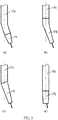
- Embodiment 1 of modulating conductive rod mechanism 17 as shown in FIG. 3 , according to a construction modulation solution of the conductive rod mechanism 17, the conductive rod mechanism 17 is composed of a conductive rod and a contact tube, and preferably adopts the following four construction forms: a bent conductive rod 17a is connected to a first straight contact tube 17b to form a bent conductive rod type curved conductive rod mechanism as shown in FIG. 3(a) ; or a first straight conductive rod 17c is connected to a bent contact tube 17d to form a bent contact tube type curved conductive rod mechanism as shown in FIG.
- a second straight conductive rod 17e is obliquely connected to a second straight contact tube 17f to form an oblique contact tube type curved conductive rod mechanism as shown in FIG. 3(c) ; or a first straight conductive rod 17c is connected to an eccentric contact tube 17g to form an eccentric conductive rod mechanism as shown in FIG. 3(d) .
- the conductive rod is preferably connected to a lower extending shaft 11b of the feeder panel by means of a connector mechanism 15 (for example, a connecting nut), which is suitable for a narrow gap or narrowing groove arc welding occasion or an application occasion that needs a lengthened conductive rod mechanism for arc welding.
- Embodiment 2 of modulating conductive rod mechanism 17 as shown in FIG. 1 and FIG. 3 , according to a construction modulation solution of the conductive rod mechanism 17, the upper end of the conductive rod mechanism 17 is directly integrated with a lower extending shaft 11b of a feeder panel without a connector mechanism 15, and in this case, the conductive rod mechanism 17 is directly composed of the lower part of the lower extending shaft 11b of the feeder panel which serves as an arc motion output shaft, and a contact tube.
- a first straight lower part of the lower extending shaft 11b of the feeder panel is connected to an eccentric contact tube 17g to form an eccentric conductive rod mechanism
- the first straight lower part of the lower extending shaft 11b of the feeder panel is connected to a bent contact tube 17d to form a bent contact tube type curved conductive rod mechanism
- a second straight lower part of the lower extending shaft 11b of the feeder panel is obliquely connected to a second straight contact tube 17f to form an oblique contact tube type curved conductive rod mechanism
- a bent lower part of the lower extending shaft 11b of the feeder panel is connected to a first straight contact tube 17b to form a bent conductive rod type curved conductive rod mechanism.
- the first straight lower part corresponds to a first straight conductive rod 17c
- the second straight lower part corresponds to a second straight conductive rod 17e
- the bent lower part corresponds to a bent conductive rod 17a.
- the curved conductive rod mechanism is preferable in application occasions with a greater arc swing/rotating radius, for example, narrow gap welding with a greater groove gap, and built-up welding and cosmetic welding, where it is preferred to implement the bent conductive rod type curved conductive rod mechanism with low cost.
- the eccentric conductive rod mechanism can be selected.
- the bent conductive rod type curved conductive rod mechanism is preferable for swing arc welding.
- the eccentric or curved conductive rod mechanism in Embodiment 1 is preferable.
- the bent contact tube type curved conductive rod mechanism is preferable during rotating arc welding in order to conveniently modulate the length of the conductive rod mechanism by replacing a contact tube, and the bent conductive rod type curved conductive rod mechanism or the eccentric conductive rod mechanism is preferable during swing arc welding.
- Embodiment 1 of extendable and retractable conductive rod mechanism 17 and extension and retraction adjusting device thereof the extendable and retractable conductive rod mechanism 17 is composed of a first extendable and retractable conductive rod with outer threads on the upper part and a contact tube connected to the lower end of the first extendable and retractable conductive rod, or is directly composed of a first extendable and retractable contact tube with outer threads on the upper part.
- the extension and retraction adjusting device of the conductive rod mechanism 17 consists of the extendable and retractable conductive rod mechanism 17, and a first locking nut 15a and an arc motion output shaft 11d, as shown in FIG. 4(a) .
- the first extendable and retractable conductive rod is a bent conductive rod 17a connected to a first straight contact tube 17b or a first straight conductive rod 17c connected to a bent contact tube 17d or an eccentric contact tube 17g or a second straight conductive rod 17e obliquely connected to a second straight contact tube 17f
- the first extendable and retractable contact tube is a bent contact tube 17d or an eccentric contact tube 17g, as shown in FIG. 3 .
- the upper end of the first extendable and retractable conductive rod or the first extendable and retractable contact tube in the extendable and retractable conductive rod mechanism 17 is screwed into a center hole in the lower part of the arc motion output shaft 11d in a relative extendable and retractable threaded connection mode, and a first locking nut 15a is screwed on outer threads of the first extendable and retractable conductive rod or the first extendable and retractable contact tube, so that the first locking nut 15a is in locking connection with the lower end surface of the arc motion output shaft 11d.
- the small diameters of the outer threads may be smaller than or greater than the outer diameter of an un-threaded section of the first extendable and retractable conductive rod or the first extendable and retractable contact tube.
- the extension and retraction adjusting device is suitable for the welding torch of the present invention, and is also suitable for other swing/rotating arc welding torches with similar functions.
- the arc motion output shaft 11d is a lower extending shaft 11b of the feeder panel
- the first locking nut 15a is one form of a connector mechanism 15 as shown in FIG. 1 .
- an inner through hole of the first locking nut 15a sequentially includes an inner threaded hole with a length of L1 and an un-threaded hole with a length of L2 from top to bottom
- the center hole in the lower part of the arc motion output shaft 11d sequentially includes an inner threaded hole with a length of L3 and an un-threaded hole with a length of L4 from bottom to top.
- the length L1 of the inner threaded hole is a thread engaging length between the first locking nut 15a and the first extendable and retractable conductive rod or the first extendable and retractable contact tube.
- the length L2 of the un-threaded hole is not smaller than an extension and retraction adjustable length L0 of the first extendable and retractable conductive rod or the first extendable and retractable contact tube, namely, L2 ⁇ L0, so that the un-threaded hole in the first locking nut 15a can cover the lower section of the outer threaded section of the first extendable and retractable conductive rod or the first extendable and retractable contact tube to protect the outer threads when a lower extension length of the first extendable and retractable conductive rod or the first extendable and retractable contact tube reaches the maximum value; preferably, (L3 + L4) is equal to (Le + L0), where Le is a shortest thread engaging length between the first extendable and retractable conductive rod or the first extendable and retractable contact tube and the arc motion output shaft 11d.
- Embodiment 2 of extendable and retractable conductive rod mechanism 17 and extension and retraction adjusting device thereof the extendable and retractable conductive rod mechanism 17 is composed of a second extendable and retractable conductive rod with outer threads on the upper part and a contact tube connected to the lower end thereof or is directly composed of a second extendable and retractable contact tube with outer threads on the upper part, where the outer threaded section is a flat cylindrical body with a waist-shaped cross section, and threads are arranged on the circular-arc surface of the flat cylindrical body.
- the extension and retraction adjusting device of the conductive rod mechanism consists of the extendable and retractable conductive rod mechanism 17, a connector mechanism 15, a directional shaft sleeve 11e and an arc motion output shaft 11d.
- the connector mechanism 15 consists of a connecting nut 15b, a T-shaped adjusting nut 15c and a second locking nut 15d.
- the directional shaft sleeve 11e is a cylindrical or a stepped cylindrical shaft sleeve with a waist-shaped through hole in the longitudinal direction, preferably a stepped cylindrical (i.e., T-shaped) shaft sleeve, and is fixedly arranged in a center hole in the lower part of the arc motion output shaft 11d for guiding the flat upper part of the second extendable and retractable conductive rod or the second extendable and retractable contact tube, so that the extendable and retractable conductive rod mechanism 17 is fixedly connected to the arc motion output shaft 11d in relatively fixed and consistent circumferential positions, as shown in FIG. 4(b) and FIG. 4(c) .
- the second extendable and retractable conductive rod is a bent conductive rod 17a connected to a first straight contact tube 17b or a first straight conductive rod 17c connected to a bent contact tube 17d or an eccentric contact tube 17g or a second straight conductive rod 17e obliquely connected to a second straight contact tube 17f
- the second extendable and retractable contact tube is a bent contact tube 17d or an eccentric contact tube 17g, as shown in FIG. 3 .
- the upper section of the outer threaded section of the second extendable and retractable conductive rod or the second extendable and retractable contact tube can be inserted into a waist-shaped through hole of the directional shaft sleeve 11e in an extendable and retractable sliding mode, a T-shaped adjusting nut 15c and a second locking nut 15d are screwed on the lower section of the outer threaded section from top to bottom in sequence.
- a connecting nut 15b is sleeved on the T-shaped adjusting nut 15c from the lower end and then is connected to the outer threads on the lower part of the arc motion output shaft 11d.
- the lower end surface of a flanging flange at the top end of the T-shaped adjusting nut 15c is pressed by inner convex shoulders at the lower end of the connecting nut 15b, so that the upper end surface of the flanging flange at the top end of the T-shaped adjusting nut 15c and the lower end surface of the arc motion output shaft 11d are in a pressing state.
- the second locking nut 15d is tightly screwed, so that the upper end surface of the second locking nut 15d and the lower end surface of the T-shaped adjusting nut 15c are in locking connection.
- the small diameters of the outer threads can be smaller than or greater than the outer diameter of an un-threaded section of the second extendable and retractable conductive rod or the second extendable and retractable contact tube.
- the extension and retraction adjusting device is suitable for the welding torch of the present invention, and is also suitable for other swing/rotating arc welding torches with similar functions.
- the arc motion output shaft 11d is a lower extending shaft 11b of the feeder panel.
- an inner through hole of the second locking nut 15d sequentially includes an inner threaded hole with a length of L5 and an un-threaded hole with a length of L6 from top to bottom.
- the center hole in the lower part of the arc motion output shaft 11d is an un-threaded hole with a length of L0.
- the length L6 of the un-threaded hole is not smaller than the extension and retraction adjustable length L0 of the second extendable and retractable conductive rod or the second extendable and retractable contact tube, namely, L6 ⁇ L0, so that the un-threaded hole in the second locking nut 15d can cover the lower section of the outer threaded section of the second extendable and retractable conductive rod or the second extendable and retractable contact tube to protect the outer threads when the lower extending-out length of the second extendable and retractable conductive rod or the second extendable and retractable contact tube reaches the maximum value.
- Embodiment 1 and Embodiment 2 of the extendable and retractable conductive rod mechanism 17 and the extension and retraction adjusting device thereof with respect to the value of the extension and retraction adjustable length L0, for example, during narrow gap or narrow groove multi-layer welding as shown in FIG. 5(a) and FIG.
- Embodiment 1 of extension and retraction adjusting method of conductive rod mechanism includes the following steps:
- the extendable and retractable conductive rod mechanism 17 is composed of the first extendable and retractable conductive rod with outer threads on the upper part and the contact tube connected to the lower end of the first extendable and retractable conductive rod or is directly composed of the first extendable and retractable contact tube with outer threads on the upper part.
- the first extendable and retractable conductive rod is a bent conductive rod 17a connected to a first straight contact tube 17b or a first straight conductive rod 17c connected to a bent contact tube 17d or an eccentric contact tube 17g or a second straight conductive rod 17e obliquely connected to a second straight contact tube 17f.
- the first extendable and retractable contact tube is the bent contact tube 17d or the eccentric contact tube 17g, as shown in FIG. 3 .
- each inward retraction adjusting amount of the first extendable and retractable conductive rod or the first extendable and retractable contact tube is approximately equal to a filler metal height h0 of a later-layer weld, as shown in FIG. 5 .
- Embodiment 2 of extension and retraction adjusting method of conductive rod mechanism includes the following steps:
- the extendable and retractable conductive rod mechanism 17 is composed of the second extendable and retractable conductive rod with outer threads on the upper part and the contact tube connected to the lower end of the second extendable and retractable conductive rod, or is directly composed of the second extendable and retractable contact tube with outer threads on the upper part, where the outer threaded section is a flat cylinder with a waist-shaped cross section.
- the second extendable and retractable conductive rod is a bent conductive rod 17a connected to a first straight contact tube 17b or a first straight conductive rod 17c connected to a bent contact tube 17d or an eccentric contact tube 17g, or a second straight conductive rod 17e obliquely connected to a second straight contact tube 17f.
- the second extendable and retractable contact tube is the bent contact tube 17d or the eccentric contact tube 17g, as shown in FIG. 3 .
- Embodiment of conductive rod mechanism modulation method when an external sleeve-shaped nozzle mechanism 28 is adopted for narrow gap or narrow groove multi-layer welding, as shown in FIG. 5 , modulation of the conductive rod mechanism includes modulation on construction of a conductive rod mechanism or length of the conductive rod mechanism.
- the conductive rod mechanism modulation method includes the following steps:
- Embodiment of motor base 9 a step-shaped center hole which is small in top and large in bottom is formed in a motor base 9 of a hollow shaft motor 4, and the motor base may be cylindrical or T-shaped or cross-shaped in shape, preferably in the shape of a cross cylinder.
- Embodiment of motor base 9 as shown in FIG. 7(a), FIG. 7(b) and FIG. 7(c), FIG. 7(a) is a front view of the motor base 9; FIG. 7(b) is a cross-sectional view at position C-C in FIG. 7(a); and FIG. 7(c) is a three-dimensional structural schematic diagram of the motor base 9.
- the motor base 9 is crossed-shaped, and includes an upper lug boss 9c, a lower convex extension 9d and convex shoulders 9b at the two sides; step-shaped center holes 9f and 9g which are small in tops and large in bottoms are formed in the motor base, the large hole 9g of the step-shaped center holes is positioned in the lower convex extension 9d of the motor base, and a stop end and a hole wall of the large hole 9g provide positioning and guiding effect for a pressing spring 6, as show in FIG. 1 , so that the large hole 9g functions as a positioning hole of the pressing spring 6.
- the upper lug boss 9c of the motor base 9 is used for fixedly mounting a hollow shaft motor 4.
- Vias 9h-9k of the connecting screws 22a-22d and vias 9m of connecting cables 7a at the two sides of the electric brush base are formed in the convex shoulders 9b at the two sides of the motor base 9, so that the motor base 9 is fixed by means of the connecting screws 22a, 22b, 22c and 22d, and the connecting cables 7a are allowed to penetrate through the motor base 9.
- a mounting hole 9a for locking/unlocking a coupling 5 is formed in one side of the motor base 9, so that a lower extending shaft 4a of the hollow shaft motor 4 can be fixedly connected to an upper extending shaft 11a of the feeder panel by means of the coupling 5 in the motor base 9, as shown in FIG. 1 .
- the vias 9m further may be C-shaped holes extending to the outer edges of the convex shoulders 9b at the two sides.
- Embodiment 1 of electric brush base 14 as shown in FIG. 8 , a screw hole 14s of a first connecting screw 22a, a screw hole 14t of a second connecting screw 22b, a screw hole 14q of a third connecting screw 22c and a screw hole 14r of a fourth connecting screw 22d are formed in four corner parts of the electric brush base 14, so that the upper end of the electric brush base 14 is fixedly connected to the convex shoulders 9b at the two sides of the motor base 9 by means of the connecting screws 22a, 22b, 22c and 22d.
- a cross counterbore 14m and a center hole which is large in top and small in bottom are sequentially formed in the middle of the electric brush base 14 longitudinally from top to bottom.
- the large center hole 14n is used for mounting a support bearing 12, and the small center hole 14p is a hole for the lower extending shaft 11b of the feeder panel to pass through.
- the cross counterbore 14m serves as a positioning slot of the electric brush 7 for positioning the electric brush 7, so that the electric brush 7 only can slide up and down along the hole wall of the cross counterbore 14m, as shown in FIG. 1 .
- Embodiment 2 of electric brush base 14 a welding shielding gas passage and/or a cooling water passage further may be arranged in the wall of an electric brush base 14, so that a welding shielding gas flows into an external nozzle mechanism through the built-in gas passage.
- the built-in gas passage includes a longitudinal gas passage, a transverse gas passage and an annular gas chamber, and also may include only a transverse gas passage and an annular gas chamber.
- the longitudinal gas passage and the transverse gas passage may be composed of one or more gas passages respectively, and preferably, the built-in passage includes two longitudinal gas passages and two transverse gas passages.
- the built-in gas passage is preferably a symmetrical structure with two or more gas passages.
- the built-in gas passage is arranged in the wall of an electric brush base 14, and includes two longitudinal gas passages 14b and 14c, two transverse gas passages 14d and 14e, and an annular gas chamber 14a.
- the annular gas chamber 14a is a central counterbore larger than the small center hole 14p, which is upwards formed in the bottom end surface of the electric brush base 14.
- the two longitudinal gas passages and the two transverse gas passages are symmetrically arranged at diagonally opposite sides of the annular gas chamber 14a, the two longitudinal gas passages 14b and 14c are positioned in the side wall of the electric brush base 14, and the two transverse gas passages 14d and 14e are positioned in the bottom wall of the electric brush base 14.
- first transverse gas passage 14d is connected to the lower end of the second longitudinal gas passage 14c and the other end of the first transverse gas passage is connected to the annular gas chamber 14a.
- One end of the second transverse gas passage 14e is connected to the lower end of the first longitudinal gas passage 14b, and the other end of the second transverse gas passage is connected to the annular gas chamber 14a.
- the upper end of the first longitudinal gas passage 14b is connected to a screw hole 14s in a first connecting screw 22a, and the upper end of the second longitudinal gas passage 14c is connected to a screw hole 14t in a second connecting screw 22b.
- an inner through hole 22e of the first connecting screw and an inner through hole 22f of the second connecting screw, which serve as welding shielding gas through holes, are respectively formed, the lower ends of the through holes are respectively connected to the first longitudinal gas passage 14b and the second longitudinal gas passage 14c by means of the screw holes 14s and 14t, and the upper ends of the through holes are connected to welding shielding gas 24a by means of quick coupling heads, so that the welding shielding gas 24a is gathered into the annular gas chamber 14a after passing through the inner through holes 22e and 22f of the connecting screws, the longitudinal gas passages 14b and 14c, and the transverse gas passages 14e and 14d, and then flows into a sleeve-shaped nozzle mechanism 28.
- the built-in cooling water passage is preferably a loop with a symmetrical structure, and is provided with at least a water inlet passage and a water outlet passage.
- the built-in cooling water passage is arranged in the wall of an electric brush base 14, and includes a longitudinal water inlet passage 14f and a longitudinal water outlet passage 14g as well as a rectangular transverse water passage consisting of first to fourth transverse water passages 14h, 14i and 14j and 14k, where the rectangular transverse water passages are symmetrically formed in the bottom wall of the electric brush base 14.
- the longitudinal water inlet passage 14f and the longitudinal water outlet passage 14g are positioned in the side wall of the electric brush base 14 and are symmetrically arranged above the transverse water passages.
- the upper end of the longitudinal water inlet passage 14f is connected to a screw hole 14q of a third connecting screw (namely, a connecting screw at the water inlet side) 22c, and the lower end of the longitudinal water inlet passage is connected to the third transverse water passage 14j in the rectangular transverse water passage.
- the upper end of the longitudinal water outlet passage 14g is connected to a screw hole 14r of a fourth connecting screw (namely, a connecting screw at the water outlet side) 22d, and the lower end of the longitudinal water outlet passage is connected to the second transverse water passage 14i in the rectangular transverse water passage.
- cooling water through holes are respectively formed, the lower ends of the through holes are respectively connected to the longitudinal water inlet passage 14f and the longitudinal water outlet passage 14g of cooling water by means of screw holes 14q and 14r, and the upper ends of the through holes are respectively connected to a cooling water leading-in end 25a and a cooling water leading-out end 25b by means of quick coupling heads, so that cooling water flows out from the inner through hole of the fourth connecting screw 22d after passing through the inner through hole of the third connecting screw 22c (namely, the connecting screw at the water inlet side), the longitudinal water inlet passage 14f, the transverse water passages and the longitudinal water outlet passage 14g, so as to form a cooling water circulating loop.
- the welding shielding gas and the welding torch cooing water are introduced by means of the inner through holes of the connecting screws used for fixed connection without additional mechanisms, so that the welding torch is more compact in structure.
- the electric brush base 14 is subjected to dual cooling effect of the welding shielding gas 24a and the cooling water 25a, so that the practicability is further improved.
- required plugs are arranged at outer outlets of the through holes of the transverse gas passages and the transverse water passages, so that an effective built-in gas passage and built-in cooling water passage are formed in the electric brush base 14.
- the transverse water passages 14h and 14i as well as 14j and 14k are arranged below the transverse gas passages 14d and 14e, so that the lower end surface of the electric brush base 14 closest to the arc is more effectively cooled.
- a welding shielding gas 24c is provided for a welding area through the built-in gas passage of the welding torch body and/or the external gas passage of the external nozzle mechanism.
- gas supply ways are preferable: a first gas supply way is a gas supply way through the built-in gas passage; as shown in FIG. 2(c) , FIG 9(a) and FIG.
- a welding shielding gas 24a is connected from the inner through hole 22e of the first connecting screw 22a and the inner through hole 22f of the second connecting screw 22b, and a welding shielding gas 24c is also provided for a welding area through the longitudinal gas passages 14b and 14c, the transverse gas passages 14e and 14d, the annular gas chamber 14a and a sleeve-shaped nozzle mechanism 28.
- a second gas supply way is a gas supply way through an external gas passage of the sleeve-shaped nozzle mechanism; as shown in FIG.
- a welding shielding gas 24b is allowed to directly flow into the external sleeve-shaped nozzle mechanism 28 through a first connecting port 30a and a second connecting port 30b of the external gas passage of the nozzle mechanism, so that a welding shielding gas 24c is provided for the welding area; in this case, the built-in gas passage in the electric brush base 14 may not be provided or used.
- a third gas supply way is a combined gas supply way through the built-in gas passage and the external gas passage of the nozzle mechanism; as shown in FIG.
- a welding shielding gas 24c is provided for the welding area in a combined mode through the first gas supply way and the second gas supply way, so that the third gas supply way is suitable for a narrow gap welding with a large gas flow or a welding occasion with a large current.
- gas is independently supplied by means of an external bias type flat-shaped nozzle mechanism (not shown) of the welding torch body, which is composed of two flat-shaped nozzles at the two sides of a conductive rod, so as to provide gas shielding for a welding arc area in a narrow gap groove, thus being suitable for a narrow gap welding occasion.
- the annular gas chamber 14a functions to gather the gas flow, and a space formed between the annular gas chamber 14a and a gas sifter 31 in the sleeve-shaped nozzle mechanism 28 further serves as a gas calming chamber.
- the gas sifter 31 is arranged in the sleeve-shaped nozzle mechanism 28, so that the welding shielding gas connected from the built-in gas passage of the welding torch body and/or the external gas passage of the nozzle mechanism, is rectified by means of the gas sifter 31, and then flows out from the nozzle mechanism.
- a flat-shaped structure capable of extending into a narrow gap welding groove is adopted.
- Swing/rotating frequency of an arc is identified/detected by means of a pre-calibration way or a built-in photoelectric encoder in a servo motor when a single-shaft extension hollow shaft motor 4 only with a lower extending shaft 4a is adopted.
- no additional sensing device for detecting the arc swing/rotating frequency and the arc swing midpoint is not arranged in the welding torch, so that the structure of the welding torch is greatly simplified, as shown in FIG. 1 .
- a double-shaft extension hollow shaft motor 4 with an upper extending shaft 4b and an lower extending shaft 4a is adopted, as shown in FIG. 2(a) and FIG.
- detection on the arc swing/rotating frequency and the arc swing midpoint can be achieved by means of a photoelectric switch device 23 which is sleeved on the upper extending shaft 4b of the motor, and in this case, the double-shaft extension hollow shaft motor 4 is preferably a step motor or a direct-current motor.
- the arc swing/rotating frequency detection and calibration methods are described below for an occasion without the additional sensing device or with the built-in photoelectric encoder:
- Embodiment of arc swing/rotating frequency calibration method when no additional sensing device for arc swing/rotating frequency detection is arranged in the arc motion mechanism, before welding, a corresponding relation between an arc swing/rotating frequency and a rotating speed control amount of the hollow shaft motor 4 is established previously in a controller of the welding torch by means of an auxiliary speed measuring device, for example, a tachymeter, so that pre-calibration on the arc swing/rotating frequency is achieved.
- the controller makes a welding arc 16 swing or rotate at a set frequency according to the calibrated value.
- the arc swing frequency calibration method includes the following steps:
- the number of times of work k of the speed measuring switch in step (1) actually reflects a ratio of the reading value of the meter to the actual value of the swing frequency
- the operation in step (1) can be replaced with the following method: calibrating the swing frequency of the meter previously by means of an existing swing arc welding torch with a real-time arc swing frequency detection function or the swing arc welding torch of the present invention adopting the photoelectric switch device 23, so as to determine a ratio k of the reading value of the meter to the actual value of the swing frequency, where k is a positive integer not smaller than 1.
- Embodiment of arc swing frequency detection method before or during swing arc welding, in a process that a welding wire 2 or an arc 16 performs left and right symmetrical circular-arc-shaped swing 18 around a swing midpoint C, a servo motor driver detects a motor rotating angle position in real time after a motor rotating angle position electric signal output by a built-in photoelectric encoder of a single-shaft extension servo hollow shaft motor 4 is decoded.
- a controller of the welding torch detects the elapsed time t1 that the motor rotates to the limit positions for every successive three times or rotates to the limit position at the same side for every successive two times.
- the spent time t1 of the motor from when the motor just rotates to the left side limit position to when the motor rotates to the right side limit position from the left side limit position after staying at the left side and just rotates back to the left side limit position after staying at the right side is detected, and during this detection, the motor rotates to the limit positions for three times (twice at the left side and once at the right side) and rotates to the left side limit position for two times, so that real-time detection on arc swing frequency f1 is achieved, where f1 is equal to 1/t1.
- the controller of the welding torch can detect electric signals of a left side positioning accomplishing pulse, a right side positioning accomplishing pulse and a left side positioning accomplishing pulse output by the servo motor driver in sequence, whereby calculation of the swing time t1 and real-time detection of the arc swing frequency f1 can be completed.
- the built-in photoelectric encoder is preferably an absolute photoelectric encoder.
- Embodiment of arc rotating frequency detection method before or during rotating arc welding, in a process that a welding wire 2 before welding or an arc 16 during welding performs unidirectional rotating motion 19 at a certain radius around a center line 1 of the welding torch, a servo motor driver detects a motor rotating angle position in real time after a motor rotating angle position electric signal output by a built-in photoelectric encoder of the single-shaft extension servo hollow shaft motor 4 is decoded, and according to a positioning accomplishing pulse electric signal for one revolution of the motor that is sent by the servo motor driver, a controller of the welding torch detect a time interval t2 between two adjacent positioning accomplishing pulses, to realize real-time detection of arc rotating frequency f2, where f2 is equal to 1/t2.
- the servo motor driver has an integrated function of position signal decoding, motor power driving, rotating position feedback and control and the like, and can adopts a commercially available standard type matched with the servo motor, similarly hereinafter.
- the detection method of the arc swing frequency/rotating frequency is also suitable for other welding torches with similar swing arc/rotating arc functions.
- FIG. 11 When a single-shaft extension servo hollow shaft motor 4 with a built-in absolute photoelectric encoder is adopted, the principle of the arc swing midpoint detection method is as shown in FIG. 11 .
- 4c is a built-in grating disc of the built-in photoelectric encoder, and is sleeved on and fixedly arranged on a motor shaft by means of a center hole 4d thereof;
- 11d is an arc motion output shaft, which is a lower extending shaft 11b of a feeder panel in the welding torch of the present invention, the lower end of the arc motion output shaft is connected to a conductive rod mechanism 17 by means of a connector mechanism 15, and the upper end of the arc motion output shaft is fixedly connected to a lower extending shaft 4a of the hollow shaft motor 4 by means of a coupler 5, as shown in FIG.
- a line O1C1 indicates a center line 1 of the welding torch
- a line A1A2 is located on the surface of a workpiece to be welded and is parallel to the direction of a welding speed Vw, and the line A1A2 represents a center line of a welding groove when the welding torch is aligned to the center of a weld
- a line CC1 is a center line of a welding wire 2 obliquely extending out from the conductive rod mechanism 17, and is crossed with the line A1A2 at a point C and with the line O1C1 at a point C1
- a line O1D indicates an initial rotating position line of the motor
- a line O1B1 indicates a motor rotating midpoint position line corresponding to the arc swing midpoint C, and is parallel to the line A1A2 and crossed with the line O1C1 at point O1.
- the hollow shaft motor 4 rotates the conductive rod mechanism 17 by means of the arc motion output shaft 11d of the welding torch or the conductive rod mechanism 17 is manually rotated.
- a motor shaft of the hollow shaft motor 4 drives the built-in grating disc 4c to synchronously rotate.
- the line A1A2, the line B1O1, the line CC1 and the line O1C1 are in the center plane of the welding torch, the crossed point C of the center line CC1 of the welding wire and the line A1A2 is an arc swing midpoint, and in this case, the current rotating position line O1B1 of the motor is a motor rotating midpoint position 33.
- a controller of the welding torch reads an absolute position angle ⁇ of motor rotation at a current position and takes the absolute position angle ⁇ as a motor rotating midpoint position 33 corresponding to an arc swing midpoint C, so that position resetting of the arc swing midpoint C after the conductive rod mechanism 17 is initially mounted or replaced is achieved.
- the welding wire 2 obliquely fed out from the conductive rod mechanism 17 is often not necessarily just bent to the front or the rear the welding direction, and as a result, it is necessary to find the arc swing midpoint C automatically or manually before each welding.
- the controller of the welding torch guides the motor to rotate to the motor rotating midpoint position 33 that is set previously, so that the welding wire 2 obliquely fed out from the eccentric or curved conductive rod mechanism 17 can be automatically bent to the front or the rear of the welding, thereby achieving automatic detection and positioning of the arc swing midpoint C before welding.
- the detection method is suitable for the welding torch of the present invention, and is also suitable for other welding torches with similar arc swing functions.
- the arc swing midpoint detection method includes the following steps:
- the curved conductive rod mechanism 17 composed of the bent conductive rod 17a and the first straight contact tube 17b or the curved conductive rod mechanism 17 composed of the second straight conductive rod 17e and the second straight contact tube 17f obliquely connected to the second straight conductive rod
- the conductive rod is fixedly connected to the arc motion output shaft 11d (for example, the lower extending shaft 11b of the feeder panel of the welding torch of the present invention) in fixed and consistent relative positions by means of the connector mechanism 15, the curving direction of the welding wire 2 relative to the arc motion output shaft 11d is always kept unchanged even after each replacement of the conductive rod or the contact tube, and correspondingly, the operation in step (1) is only used during initial mounting and debugging of the conductive rod mechanism 17.
- the contact tube and the arc motion output shaft 11d can be always fixedly connected in fixed and consistent relative positions without the connector mechanism 15, and correspondingly, the operation in step (1) is only used during initial mounting and debugging of the conductive rod mechanism 17.
Landscapes
- Engineering & Computer Science (AREA)
- Physics & Mathematics (AREA)
- Plasma & Fusion (AREA)
- Mechanical Engineering (AREA)
- Power Engineering (AREA)
- Microelectronics & Electronic Packaging (AREA)
- Arc Welding In General (AREA)
Applications Claiming Priority (2)
| Application Number | Priority Date | Filing Date | Title |
|---|---|---|---|
| CN202010337635.6A CN111390358B (zh) | 2020-04-26 | 2020-04-26 | 摇动/旋转电弧熔化极气体保护焊炬及其使用方法 |
| PCT/CN2020/116117 WO2021218005A1 (zh) | 2020-04-26 | 2020-09-18 | 摇动/旋转电弧熔化极气体保护焊炬及其使用方法 |
Publications (3)
| Publication Number | Publication Date |
|---|---|
| EP4019178A1 true EP4019178A1 (de) | 2022-06-29 |
| EP4019178A4 EP4019178A4 (de) | 2023-01-25 |
| EP4019178B1 EP4019178B1 (de) | 2023-09-13 |
Family
ID=71417107
Family Applications (1)
| Application Number | Title | Priority Date | Filing Date |
|---|---|---|---|
| EP20933162.8A Active EP4019178B1 (de) | 2020-04-26 | 2020-09-18 | Schwingender /rotierender gas-metall-lichtbogenschweissbrenner und verfahren zu seiner verwendung |
Country Status (4)
| Country | Link |
|---|---|
| US (1) | US11583949B2 (de) |
| EP (1) | EP4019178B1 (de) |
| CN (1) | CN111390358B (de) |
| WO (1) | WO2021218005A1 (de) |
Families Citing this family (15)
| Publication number | Priority date | Publication date | Assignee | Title |
|---|---|---|---|---|
| CN111390358B (zh) * | 2020-04-26 | 2021-07-13 | 江苏科技大学 | 摇动/旋转电弧熔化极气体保护焊炬及其使用方法 |
| CN112894073B (zh) * | 2020-12-23 | 2022-09-27 | 苏州弧瀚科技有限公司 | 一种利用旋转电极复合旋转电弧的窄间隙焊接方法 |
| CN113042855B (zh) * | 2021-04-07 | 2023-03-10 | 德州学院 | 钢轨焊接方法及装置 |
| CN113399801B (zh) * | 2021-06-10 | 2023-04-21 | 中车青岛四方机车车辆股份有限公司 | 抑制焊接热裂纹的焊接装置及焊接系统 |
| CN113681135A (zh) * | 2021-09-01 | 2021-11-23 | 江苏科技大学 | 可喷出稳定气流的气体保护焊用可伸缩喷嘴及其使用方法 |
| CN113941763B (zh) * | 2021-11-22 | 2023-07-25 | 江苏科技大学 | 一种采用粗焊丝的摇动/旋转电弧熔化极焊接方法 |
| CN114378510B (zh) * | 2021-12-14 | 2025-03-25 | 浙江华熔科技股份有限公司 | 一种人造石墨焊接预备装置 |
| CN114226929A (zh) * | 2021-12-21 | 2022-03-25 | 武汉纳瑞格智能设备有限公司 | 一种高效冷却的板式窄间隙mag/mig焊枪 |
| CN114393286B (zh) * | 2022-01-19 | 2023-05-26 | 湘潭大学 | 一种用于机械手的扭转摆动电弧的焊缝偏差提取方法 |
| CN114951926B (zh) * | 2022-07-05 | 2024-04-05 | 上海中船三井造船柴油机有限公司 | 一种用于管道焊接的微型曲线摆动装置 |
| CN117798473B (zh) * | 2024-02-29 | 2024-06-07 | 广东福维德焊接股份有限公司 | 一种非熔化极旋转焊枪 |
| CN117900710B (zh) * | 2024-03-18 | 2024-05-28 | 常州市佳乐车辆配件制造有限公司 | 一种转向管柱后支架总成焊接设备 |
| CN117961295B (zh) * | 2024-03-29 | 2024-06-21 | 巢湖学院 | 一种矿井定位部件的焊接装置 |
| CN119973301A (zh) * | 2025-03-17 | 2025-05-13 | 江苏科技大学 | 宽频可调摇动电弧焊接方法及焊炬与应用 |
| CN120533408B (zh) * | 2025-07-23 | 2026-01-06 | 温州市明洋管件制造有限公司 | 一种管件焊接设备及其使用方法 |
Family Cites Families (15)
| Publication number | Priority date | Publication date | Assignee | Title |
|---|---|---|---|---|
| US4401878A (en) | 1981-03-30 | 1983-08-30 | Rsr Systems, Inc. | Consumable arc welding torch |
| JPS63317263A (ja) * | 1987-06-18 | 1988-12-26 | Ishikawajima Harima Heavy Ind Co Ltd | 溶接ト−チ |
| JP3261788B2 (ja) * | 1993-02-01 | 2002-03-04 | 株式会社安川電機 | ロボット用溶接トーチの集電装置 |
| CN1323788C (zh) * | 2005-03-23 | 2007-07-04 | 江苏科技大学 | 空心轴电机驱动的旋转电弧窄间隙焊接方法及装置 |
| JP2007098419A (ja) * | 2005-10-03 | 2007-04-19 | Jfe Engineering Kk | 回転アーク溶接トーチ |
| CN101412143B (zh) * | 2008-11-19 | 2011-06-01 | 江苏科技大学 | 摇动电弧窄间隙熔化极气体保护焊接方法及焊炬 |
| CN102398100B (zh) * | 2011-04-07 | 2014-07-23 | 江苏科技大学 | 摇动电弧窄间隙焊接系统的控制方法及装置 |
| CN102275029B (zh) * | 2011-07-19 | 2013-05-15 | 江苏科技大学 | 摇动电弧窄间隙熔化极气体保护立向焊接方法 |
| CN103264212B (zh) * | 2013-05-08 | 2015-04-08 | 江苏科技大学 | 用于旋转电弧焊接的可调配焊炬及其调配方法 |
| CN103639568A (zh) * | 2013-12-25 | 2014-03-19 | 江苏新瑞峰信息科技有限公司 | 一种焊接电弧摇动装置 |
| US20180345402A1 (en) * | 2015-05-08 | 2018-12-06 | Weld Revolution, LLC | Improved Apparatus for Use of Rotating Arc Process Welding |
| CN105033413A (zh) * | 2015-06-29 | 2015-11-11 | 张洪涛 | 一种钨极自转式非熔化极氩弧焊接装置 |
| CN106180990B (zh) * | 2016-08-05 | 2018-05-08 | 太原理工大学 | 一种无级可调的偏心旋转熔化极气体保护焊枪 |
| CN106180994B (zh) | 2016-08-10 | 2018-10-19 | 哈尔滨工业大学(威海) | 一种旋摆式焊炬及焊接方法 |
| CN111390358B (zh) * | 2020-04-26 | 2021-07-13 | 江苏科技大学 | 摇动/旋转电弧熔化极气体保护焊炬及其使用方法 |
-
2020
- 2020-04-26 CN CN202010337635.6A patent/CN111390358B/zh active Active
- 2020-09-18 WO PCT/CN2020/116117 patent/WO2021218005A1/zh not_active Ceased
- 2020-09-18 EP EP20933162.8A patent/EP4019178B1/de active Active
- 2020-09-18 US US17/764,984 patent/US11583949B2/en active Active
Also Published As
| Publication number | Publication date |
|---|---|
| WO2021218005A1 (zh) | 2021-11-04 |
| EP4019178A4 (de) | 2023-01-25 |
| CN111390358B (zh) | 2021-07-13 |
| US11583949B2 (en) | 2023-02-21 |
| US20220388088A1 (en) | 2022-12-08 |
| CN111390358A (zh) | 2020-07-10 |
| EP4019178B1 (de) | 2023-09-13 |
Similar Documents
| Publication | Publication Date | Title |
|---|---|---|
| EP4019178B1 (de) | Schwingender /rotierender gas-metall-lichtbogenschweissbrenner und verfahren zu seiner verwendung | |
| CN204366245U (zh) | 螺旋缝埋弧焊管外焊缝的焊接装置 | |
| DE4143414C2 (de) | Werkzeugkopf mit automatisch verstellbarer Fokussierungsoptik | |
| CN116586766B (zh) | 一种基于汽车零部件加工用焊接设备 | |
| CN112077487B (zh) | 一种用于机器人焊接的激光辅助示教编程装置 | |
| CN109926694B (zh) | 一种焊接机器人 | |
| CN112276312B (zh) | 瓜瓣焊接轨迹自识别的深窄间隙埋弧焊装置及焊接方法 | |
| CN105312731A (zh) | 基于递送边位移传感的螺旋钢管内焊焊缝自动跟踪方法 | |
| CN112192071A (zh) | 一种传动轴总成校直焊接工艺 | |
| CN112719699B (zh) | 一种焊接装置的监控方法 | |
| US20230050221A1 (en) | Resistance Multi Purpose Welder Attachment | |
| US8304680B2 (en) | Portable bore welding machine | |
| DE3117606A1 (de) | "automatisch, beruehrungslose brennerfuehrung auf fugenmitte beim schutzgas-lichtbogenschweissen" | |
| JPH0225279A (ja) | 軌道式溶接ヘッドツール | |
| CN114226921B (zh) | 一种焊枪及立柱焊接装置 | |
| CN117464210A (zh) | 一种环形焊缝激光对中摆丝检测装置及其使用方法 | |
| CN212239749U (zh) | 地轨式三轴自动焊接设备 | |
| KR101010775B1 (ko) | 아크센서 교정을 통한 용접선 자동 추종방법 | |
| CN108941906B (zh) | 一种多功能激光锡焊机 | |
| DE1652814C3 (de) | Vorrichtung zum Lichtbogenschweißen von Innen-Rundnähten | |
| JP2005040858A (ja) | 溶接ユニット装置 | |
| CN209681471U (zh) | 一种新型钢管对焊机结构 | |
| CN216594532U (zh) | 一种焊接强度检测机构 | |
| CN112719684B (zh) | 一种带有跟踪定位功能的焊接用机器视觉监测装置 | |
| CN213224812U (zh) | 一种具有调节结构活塞杆生产焊接装置 |
Legal Events
| Date | Code | Title | Description |
|---|---|---|---|
| STAA | Information on the status of an ep patent application or granted ep patent |
Free format text: STATUS: THE INTERNATIONAL PUBLICATION HAS BEEN MADE |
|
| PUAI | Public reference made under article 153(3) epc to a published international application that has entered the european phase |
Free format text: ORIGINAL CODE: 0009012 |
|
| STAA | Information on the status of an ep patent application or granted ep patent |
Free format text: STATUS: REQUEST FOR EXAMINATION WAS MADE |
|
| 17P | Request for examination filed |
Effective date: 20220324 |
|
| AK | Designated contracting states |
Kind code of ref document: A1 Designated state(s): AL AT BE BG CH CY CZ DE DK EE ES FI FR GB GR HR HU IE IS IT LI LT LU LV MC MK MT NL NO PL PT RO RS SE SI SK SM TR |
|
| RAP1 | Party data changed (applicant data changed or rights of an application transferred) |
Owner name: JIANGSU UNIVERSITY OF SCIENCE AND TECHNOLOGY |
|
| RIN1 | Information on inventor provided before grant (corrected) |
Inventor name: ZHANG, LUXIAO Inventor name: PANG, JIANJIAN Inventor name: JIANG, YUQING Inventor name: WANG, BIAO Inventor name: JIANG, DA Inventor name: WANG, KAI Inventor name: WANG, TIANWEI Inventor name: ZHU, JIE Inventor name: WANG, JIAYOU |
|
| RIN1 | Information on inventor provided before grant (corrected) |
Inventor name: MARKSYMOV, SERGIL Inventor name: WANG, JIANXIN Inventor name: JIANG, YUQING Inventor name: WANG, BIAO Inventor name: JIANG, DA Inventor name: WANG, TIANWEI Inventor name: ZHU, JIE Inventor name: WANG, JIAYOU |
|
| RIN1 | Information on inventor provided before grant (corrected) |
Inventor name: MARKSYMOV, SERGII Inventor name: WANG, JIANXIN Inventor name: JIANG, YUQING Inventor name: WANG, BIAO Inventor name: JIANG, DA Inventor name: WANG, TIANWEI Inventor name: ZHU, JIE Inventor name: WANG, JIAYOU |
|
| RIN1 | Information on inventor provided before grant (corrected) |
Inventor name: MAKSYMOV, SERGII Inventor name: WANG, JIANXIN Inventor name: JIANG, YUQING Inventor name: WANG, BIAO Inventor name: JIANG, DA Inventor name: WANG, TIANWEI Inventor name: ZHU, JIE Inventor name: WANG, JIAYOU |
|
| A4 | Supplementary search report drawn up and despatched |
Effective date: 20221222 |
|
| RIC1 | Information provided on ipc code assigned before grant |
Ipc: B23K 9/29 20060101ALI20221216BHEP Ipc: B23K 9/02 20060101ALI20221216BHEP Ipc: B23K 9/18 20060101ALI20221216BHEP Ipc: B23K 9/12 20060101ALI20221216BHEP Ipc: B23K 9/173 20060101ALI20221216BHEP Ipc: B23K 9/28 20060101AFI20221216BHEP |
|
| GRAP | Despatch of communication of intention to grant a patent |
Free format text: ORIGINAL CODE: EPIDOSNIGR1 |
|
| STAA | Information on the status of an ep patent application or granted ep patent |
Free format text: STATUS: GRANT OF PATENT IS INTENDED |
|
| RIC1 | Information provided on ipc code assigned before grant |
Ipc: B23K 9/29 20060101ALI20230428BHEP Ipc: B23K 9/02 20060101ALI20230428BHEP Ipc: B23K 9/18 20060101ALI20230428BHEP Ipc: B23K 9/12 20060101ALI20230428BHEP Ipc: B23K 9/173 20060101ALI20230428BHEP Ipc: B23K 9/28 20060101AFI20230428BHEP |
|
| DAV | Request for validation of the european patent (deleted) | ||
| DAX | Request for extension of the european patent (deleted) | ||
| INTG | Intention to grant announced |
Effective date: 20230517 |
|
| GRAS | Grant fee paid |
Free format text: ORIGINAL CODE: EPIDOSNIGR3 |
|
| GRAA | (expected) grant |
Free format text: ORIGINAL CODE: 0009210 |
|
| STAA | Information on the status of an ep patent application or granted ep patent |
Free format text: STATUS: THE PATENT HAS BEEN GRANTED |
|
| AK | Designated contracting states |
Kind code of ref document: B1 Designated state(s): AL AT BE BG CH CY CZ DE DK EE ES FI FR GB GR HR HU IE IS IT LI LT LU LV MC MK MT NL NO PL PT RO RS SE SI SK SM TR |
|
| REG | Reference to a national code |
Ref country code: CH Ref legal event code: EP |
|
| REG | Reference to a national code |
Ref country code: DE Ref legal event code: R096 Ref document number: 602020017814 Country of ref document: DE |
|
| REG | Reference to a national code |
Ref country code: IE Ref legal event code: FG4D |
|
| REG | Reference to a national code |
Ref country code: LT Ref legal event code: MG9D |
|
| REG | Reference to a national code |
Ref country code: NL Ref legal event code: MP Effective date: 20230913 |
|
| PG25 | Lapsed in a contracting state [announced via postgrant information from national office to epo] |
Ref country code: GR Free format text: LAPSE BECAUSE OF FAILURE TO SUBMIT A TRANSLATION OF THE DESCRIPTION OR TO PAY THE FEE WITHIN THE PRESCRIBED TIME-LIMIT Effective date: 20231214 |
|
| PG25 | Lapsed in a contracting state [announced via postgrant information from national office to epo] |
Ref country code: SE Free format text: LAPSE BECAUSE OF FAILURE TO SUBMIT A TRANSLATION OF THE DESCRIPTION OR TO PAY THE FEE WITHIN THE PRESCRIBED TIME-LIMIT Effective date: 20230913 Ref country code: RS Free format text: LAPSE BECAUSE OF FAILURE TO SUBMIT A TRANSLATION OF THE DESCRIPTION OR TO PAY THE FEE WITHIN THE PRESCRIBED TIME-LIMIT Effective date: 20230913 Ref country code: NO Free format text: LAPSE BECAUSE OF FAILURE TO SUBMIT A TRANSLATION OF THE DESCRIPTION OR TO PAY THE FEE WITHIN THE PRESCRIBED TIME-LIMIT Effective date: 20231213 Ref country code: LV Free format text: LAPSE BECAUSE OF FAILURE TO SUBMIT A TRANSLATION OF THE DESCRIPTION OR TO PAY THE FEE WITHIN THE PRESCRIBED TIME-LIMIT Effective date: 20230913 Ref country code: LT Free format text: LAPSE BECAUSE OF FAILURE TO SUBMIT A TRANSLATION OF THE DESCRIPTION OR TO PAY THE FEE WITHIN THE PRESCRIBED TIME-LIMIT Effective date: 20230913 Ref country code: HR Free format text: LAPSE BECAUSE OF FAILURE TO SUBMIT A TRANSLATION OF THE DESCRIPTION OR TO PAY THE FEE WITHIN THE PRESCRIBED TIME-LIMIT Effective date: 20230913 Ref country code: GR Free format text: LAPSE BECAUSE OF FAILURE TO SUBMIT A TRANSLATION OF THE DESCRIPTION OR TO PAY THE FEE WITHIN THE PRESCRIBED TIME-LIMIT Effective date: 20231214 Ref country code: FI Free format text: LAPSE BECAUSE OF FAILURE TO SUBMIT A TRANSLATION OF THE DESCRIPTION OR TO PAY THE FEE WITHIN THE PRESCRIBED TIME-LIMIT Effective date: 20230913 |
|
| REG | Reference to a national code |
Ref country code: AT Ref legal event code: MK05 Ref document number: 1610769 Country of ref document: AT Kind code of ref document: T Effective date: 20230913 |
|
| PG25 | Lapsed in a contracting state [announced via postgrant information from national office to epo] |
Ref country code: NL Free format text: LAPSE BECAUSE OF FAILURE TO SUBMIT A TRANSLATION OF THE DESCRIPTION OR TO PAY THE FEE WITHIN THE PRESCRIBED TIME-LIMIT Effective date: 20230913 |
|
| PG25 | Lapsed in a contracting state [announced via postgrant information from national office to epo] |
Ref country code: IS Free format text: LAPSE BECAUSE OF FAILURE TO SUBMIT A TRANSLATION OF THE DESCRIPTION OR TO PAY THE FEE WITHIN THE PRESCRIBED TIME-LIMIT Effective date: 20240113 |
|
| PG25 | Lapsed in a contracting state [announced via postgrant information from national office to epo] |
Ref country code: AT Free format text: LAPSE BECAUSE OF FAILURE TO SUBMIT A TRANSLATION OF THE DESCRIPTION OR TO PAY THE FEE WITHIN THE PRESCRIBED TIME-LIMIT Effective date: 20230913 |
|
| PG25 | Lapsed in a contracting state [announced via postgrant information from national office to epo] |
Ref country code: ES Free format text: LAPSE BECAUSE OF FAILURE TO SUBMIT A TRANSLATION OF THE DESCRIPTION OR TO PAY THE FEE WITHIN THE PRESCRIBED TIME-LIMIT Effective date: 20230913 |
|
| PG25 | Lapsed in a contracting state [announced via postgrant information from national office to epo] |
Ref country code: SM Free format text: LAPSE BECAUSE OF FAILURE TO SUBMIT A TRANSLATION OF THE DESCRIPTION OR TO PAY THE FEE WITHIN THE PRESCRIBED TIME-LIMIT Effective date: 20230913 Ref country code: RO Free format text: LAPSE BECAUSE OF FAILURE TO SUBMIT A TRANSLATION OF THE DESCRIPTION OR TO PAY THE FEE WITHIN THE PRESCRIBED TIME-LIMIT Effective date: 20230913 Ref country code: IS Free format text: LAPSE BECAUSE OF FAILURE TO SUBMIT A TRANSLATION OF THE DESCRIPTION OR TO PAY THE FEE WITHIN THE PRESCRIBED TIME-LIMIT Effective date: 20240113 Ref country code: ES Free format text: LAPSE BECAUSE OF FAILURE TO SUBMIT A TRANSLATION OF THE DESCRIPTION OR TO PAY THE FEE WITHIN THE PRESCRIBED TIME-LIMIT Effective date: 20230913 Ref country code: EE Free format text: LAPSE BECAUSE OF FAILURE TO SUBMIT A TRANSLATION OF THE DESCRIPTION OR TO PAY THE FEE WITHIN THE PRESCRIBED TIME-LIMIT Effective date: 20230913 Ref country code: CZ Free format text: LAPSE BECAUSE OF FAILURE TO SUBMIT A TRANSLATION OF THE DESCRIPTION OR TO PAY THE FEE WITHIN THE PRESCRIBED TIME-LIMIT Effective date: 20230913 Ref country code: AT Free format text: LAPSE BECAUSE OF FAILURE TO SUBMIT A TRANSLATION OF THE DESCRIPTION OR TO PAY THE FEE WITHIN THE PRESCRIBED TIME-LIMIT Effective date: 20230913 Ref country code: PT Free format text: LAPSE BECAUSE OF FAILURE TO SUBMIT A TRANSLATION OF THE DESCRIPTION OR TO PAY THE FEE WITHIN THE PRESCRIBED TIME-LIMIT Effective date: 20240115 Ref country code: SK Free format text: LAPSE BECAUSE OF FAILURE TO SUBMIT A TRANSLATION OF THE DESCRIPTION OR TO PAY THE FEE WITHIN THE PRESCRIBED TIME-LIMIT Effective date: 20230913 |
|
| REG | Reference to a national code |
Ref country code: CH Ref legal event code: PL |
|
| PG25 | Lapsed in a contracting state [announced via postgrant information from national office to epo] |
Ref country code: LU Free format text: LAPSE BECAUSE OF NON-PAYMENT OF DUE FEES Effective date: 20230918 |
|
| REG | Reference to a national code |
Ref country code: BE Ref legal event code: MM Effective date: 20230930 |
|
| PG25 | Lapsed in a contracting state [announced via postgrant information from national office to epo] |
Ref country code: PL Free format text: LAPSE BECAUSE OF FAILURE TO SUBMIT A TRANSLATION OF THE DESCRIPTION OR TO PAY THE FEE WITHIN THE PRESCRIBED TIME-LIMIT Effective date: 20230913 Ref country code: LU Free format text: LAPSE BECAUSE OF NON-PAYMENT OF DUE FEES Effective date: 20230918 Ref country code: IT Free format text: LAPSE BECAUSE OF FAILURE TO SUBMIT A TRANSLATION OF THE DESCRIPTION OR TO PAY THE FEE WITHIN THE PRESCRIBED TIME-LIMIT Effective date: 20230913 |
|
| REG | Reference to a national code |
Ref country code: DE Ref legal event code: R097 Ref document number: 602020017814 Country of ref document: DE |
|
| PG25 | Lapsed in a contracting state [announced via postgrant information from national office to epo] |
Ref country code: MC Free format text: LAPSE BECAUSE OF FAILURE TO SUBMIT A TRANSLATION OF THE DESCRIPTION OR TO PAY THE FEE WITHIN THE PRESCRIBED TIME-LIMIT Effective date: 20230913 |
|
| REG | Reference to a national code |
Ref country code: IE Ref legal event code: MM4A |
|
| PG25 | Lapsed in a contracting state [announced via postgrant information from national office to epo] |
Ref country code: IE Free format text: LAPSE BECAUSE OF NON-PAYMENT OF DUE FEES Effective date: 20230918 |
|
| PG25 | Lapsed in a contracting state [announced via postgrant information from national office to epo] |
Ref country code: DK Free format text: LAPSE BECAUSE OF FAILURE TO SUBMIT A TRANSLATION OF THE DESCRIPTION OR TO PAY THE FEE WITHIN THE PRESCRIBED TIME-LIMIT Effective date: 20230913 |
|
| PG25 | Lapsed in a contracting state [announced via postgrant information from national office to epo] |
Ref country code: CH Free format text: LAPSE BECAUSE OF NON-PAYMENT OF DUE FEES Effective date: 20230930 |
|
| PLBE | No opposition filed within time limit |
Free format text: ORIGINAL CODE: 0009261 |
|
| STAA | Information on the status of an ep patent application or granted ep patent |
Free format text: STATUS: NO OPPOSITION FILED WITHIN TIME LIMIT |
|
| PG25 | Lapsed in a contracting state [announced via postgrant information from national office to epo] |
Ref country code: MC Free format text: LAPSE BECAUSE OF FAILURE TO SUBMIT A TRANSLATION OF THE DESCRIPTION OR TO PAY THE FEE WITHIN THE PRESCRIBED TIME-LIMIT Effective date: 20230913 Ref country code: IE Free format text: LAPSE BECAUSE OF NON-PAYMENT OF DUE FEES Effective date: 20230918 Ref country code: DK Free format text: LAPSE BECAUSE OF FAILURE TO SUBMIT A TRANSLATION OF THE DESCRIPTION OR TO PAY THE FEE WITHIN THE PRESCRIBED TIME-LIMIT Effective date: 20230913 Ref country code: CH Free format text: LAPSE BECAUSE OF NON-PAYMENT OF DUE FEES Effective date: 20230930 |
|
| 26N | No opposition filed |
Effective date: 20240614 |
|
| PG25 | Lapsed in a contracting state [announced via postgrant information from national office to epo] |
Ref country code: BE Free format text: LAPSE BECAUSE OF NON-PAYMENT OF DUE FEES Effective date: 20230930 |
|
| PG25 | Lapsed in a contracting state [announced via postgrant information from national office to epo] |
Ref country code: SI Free format text: LAPSE BECAUSE OF FAILURE TO SUBMIT A TRANSLATION OF THE DESCRIPTION OR TO PAY THE FEE WITHIN THE PRESCRIBED TIME-LIMIT Effective date: 20230913 |
|
| PG25 | Lapsed in a contracting state [announced via postgrant information from national office to epo] |
Ref country code: SI Free format text: LAPSE BECAUSE OF FAILURE TO SUBMIT A TRANSLATION OF THE DESCRIPTION OR TO PAY THE FEE WITHIN THE PRESCRIBED TIME-LIMIT Effective date: 20230913 |
|
| PG25 | Lapsed in a contracting state [announced via postgrant information from national office to epo] |
Ref country code: BG Free format text: LAPSE BECAUSE OF FAILURE TO SUBMIT A TRANSLATION OF THE DESCRIPTION OR TO PAY THE FEE WITHIN THE PRESCRIBED TIME-LIMIT Effective date: 20230913 |
|
| PG25 | Lapsed in a contracting state [announced via postgrant information from national office to epo] |
Ref country code: BG Free format text: LAPSE BECAUSE OF FAILURE TO SUBMIT A TRANSLATION OF THE DESCRIPTION OR TO PAY THE FEE WITHIN THE PRESCRIBED TIME-LIMIT Effective date: 20230913 |
|
| GBPC | Gb: european patent ceased through non-payment of renewal fee |
Effective date: 20240918 |
|
| PG25 | Lapsed in a contracting state [announced via postgrant information from national office to epo] |
Ref country code: GB Free format text: LAPSE BECAUSE OF NON-PAYMENT OF DUE FEES Effective date: 20240918 |
|
| PG25 | Lapsed in a contracting state [announced via postgrant information from national office to epo] |
Ref country code: CY Free format text: LAPSE BECAUSE OF FAILURE TO SUBMIT A TRANSLATION OF THE DESCRIPTION OR TO PAY THE FEE WITHIN THE PRESCRIBED TIME-LIMIT; INVALID AB INITIO Effective date: 20200918 |
|
| PG25 | Lapsed in a contracting state [announced via postgrant information from national office to epo] |
Ref country code: HU Free format text: LAPSE BECAUSE OF FAILURE TO SUBMIT A TRANSLATION OF THE DESCRIPTION OR TO PAY THE FEE WITHIN THE PRESCRIBED TIME-LIMIT; INVALID AB INITIO Effective date: 20200918 |
|
| PGFP | Annual fee paid to national office [announced via postgrant information from national office to epo] |
Ref country code: DE Payment date: 20250916 Year of fee payment: 6 |
|
| PGFP | Annual fee paid to national office [announced via postgrant information from national office to epo] |
Ref country code: FR Payment date: 20250929 Year of fee payment: 6 |
|
| PG25 | Lapsed in a contracting state [announced via postgrant information from national office to epo] |
Ref country code: TR Free format text: LAPSE BECAUSE OF FAILURE TO SUBMIT A TRANSLATION OF THE DESCRIPTION OR TO PAY THE FEE WITHIN THE PRESCRIBED TIME-LIMIT Effective date: 20230913 |