EP4017715B1 - Verfahren zur instandsetzung von strukturierten oberflächen - Google Patents
Verfahren zur instandsetzung von strukturierten oberflächen Download PDFInfo
- Publication number
- EP4017715B1 EP4017715B1 EP20760430.7A EP20760430A EP4017715B1 EP 4017715 B1 EP4017715 B1 EP 4017715B1 EP 20760430 A EP20760430 A EP 20760430A EP 4017715 B1 EP4017715 B1 EP 4017715B1
- Authority
- EP
- European Patent Office
- Prior art keywords
- die
- damage location
- cured
- damaged area
- curable
- Prior art date
- Legal status (The legal status is an assumption and is not a legal conclusion. Google has not performed a legal analysis and makes no representation as to the accuracy of the status listed.)
- Active
Links
Images

Classifications
-
- B—PERFORMING OPERATIONS; TRANSPORTING
- B29—WORKING OF PLASTICS; WORKING OF SUBSTANCES IN A PLASTIC STATE IN GENERAL
- B29C—SHAPING OR JOINING OF PLASTICS; SHAPING OF MATERIAL IN A PLASTIC STATE, NOT OTHERWISE PROVIDED FOR; AFTER-TREATMENT OF THE SHAPED PRODUCTS, e.g. REPAIRING
- B29C73/00—Repairing of articles made from plastics or substances in a plastic state, e.g. of articles shaped or produced by using techniques covered by this subclass or subclass B29D
- B29C73/04—Repairing of articles made from plastics or substances in a plastic state, e.g. of articles shaped or produced by using techniques covered by this subclass or subclass B29D using preformed elements
- B29C73/10—Repairing of articles made from plastics or substances in a plastic state, e.g. of articles shaped or produced by using techniques covered by this subclass or subclass B29D using preformed elements using patches sealing on the surface of the article
-
- B—PERFORMING OPERATIONS; TRANSPORTING
- B29—WORKING OF PLASTICS; WORKING OF SUBSTANCES IN A PLASTIC STATE IN GENERAL
- B29C—SHAPING OR JOINING OF PLASTICS; SHAPING OF MATERIAL IN A PLASTIC STATE, NOT OTHERWISE PROVIDED FOR; AFTER-TREATMENT OF THE SHAPED PRODUCTS, e.g. REPAIRING
- B29C35/00—Heating, cooling or curing, e.g. crosslinking or vulcanising; Apparatus therefor
- B29C35/02—Heating or curing, e.g. crosslinking or vulcanizing during moulding, e.g. in a mould
- B29C35/08—Heating or curing, e.g. crosslinking or vulcanizing during moulding, e.g. in a mould by wave energy or particle radiation
- B29C35/0805—Heating or curing, e.g. crosslinking or vulcanizing during moulding, e.g. in a mould by wave energy or particle radiation using electromagnetic radiation
-
- B—PERFORMING OPERATIONS; TRANSPORTING
- B29—WORKING OF PLASTICS; WORKING OF SUBSTANCES IN A PLASTIC STATE IN GENERAL
- B29C—SHAPING OR JOINING OF PLASTICS; SHAPING OF MATERIAL IN A PLASTIC STATE, NOT OTHERWISE PROVIDED FOR; AFTER-TREATMENT OF THE SHAPED PRODUCTS, e.g. REPAIRING
- B29C73/00—Repairing of articles made from plastics or substances in a plastic state, e.g. of articles shaped or produced by using techniques covered by this subclass or subclass B29D
- B29C73/02—Repairing of articles made from plastics or substances in a plastic state, e.g. of articles shaped or produced by using techniques covered by this subclass or subclass B29D using liquid or paste-like material
-
- B—PERFORMING OPERATIONS; TRANSPORTING
- B29—WORKING OF PLASTICS; WORKING OF SUBSTANCES IN A PLASTIC STATE IN GENERAL
- B29C—SHAPING OR JOINING OF PLASTICS; SHAPING OF MATERIAL IN A PLASTIC STATE, NOT OTHERWISE PROVIDED FOR; AFTER-TREATMENT OF THE SHAPED PRODUCTS, e.g. REPAIRING
- B29C73/00—Repairing of articles made from plastics or substances in a plastic state, e.g. of articles shaped or produced by using techniques covered by this subclass or subclass B29D
- B29C73/24—Apparatus or accessories not otherwise provided for
- B29C73/26—Apparatus or accessories not otherwise provided for for mechanical pretreatment
-
- B—PERFORMING OPERATIONS; TRANSPORTING
- B29—WORKING OF PLASTICS; WORKING OF SUBSTANCES IN A PLASTIC STATE IN GENERAL
- B29C—SHAPING OR JOINING OF PLASTICS; SHAPING OF MATERIAL IN A PLASTIC STATE, NOT OTHERWISE PROVIDED FOR; AFTER-TREATMENT OF THE SHAPED PRODUCTS, e.g. REPAIRING
- B29C73/00—Repairing of articles made from plastics or substances in a plastic state, e.g. of articles shaped or produced by using techniques covered by this subclass or subclass B29D
- B29C73/24—Apparatus or accessories not otherwise provided for
- B29C73/30—Apparatus or accessories not otherwise provided for for local pressing or local heating
- B29C73/34—Apparatus or accessories not otherwise provided for for local pressing or local heating for local heating
-
- B—PERFORMING OPERATIONS; TRANSPORTING
- B29—WORKING OF PLASTICS; WORKING OF SUBSTANCES IN A PLASTIC STATE IN GENERAL
- B29C—SHAPING OR JOINING OF PLASTICS; SHAPING OF MATERIAL IN A PLASTIC STATE, NOT OTHERWISE PROVIDED FOR; AFTER-TREATMENT OF THE SHAPED PRODUCTS, e.g. REPAIRING
- B29C35/00—Heating, cooling or curing, e.g. crosslinking or vulcanising; Apparatus therefor
- B29C35/02—Heating or curing, e.g. crosslinking or vulcanizing during moulding, e.g. in a mould
- B29C35/08—Heating or curing, e.g. crosslinking or vulcanizing during moulding, e.g. in a mould by wave energy or particle radiation
- B29C35/0805—Heating or curing, e.g. crosslinking or vulcanizing during moulding, e.g. in a mould by wave energy or particle radiation using electromagnetic radiation
- B29C2035/0827—Heating or curing, e.g. crosslinking or vulcanizing during moulding, e.g. in a mould by wave energy or particle radiation using electromagnetic radiation using UV radiation
Definitions
- the invention relates to a method for repairing structured surfaces of a component.
- surfaces which face a user when in use can have a structured surface in order to give the user a desired visual and/or tactile impression.
- structured surfaces together with suitable coloring to create the impression of a different material than the material actually used for the component.
- wood or stone surfaces can be recreated particularly realistically using plastics if the wood grain or stone roughness is reproduced on the surface of the component.
- corresponding components with structured surfaces are so-called designer floor coverings made of polyvinyl chloride (PVC), which can have a stone, tile or wood look, kitchen worktops made of synthetic resin with a stone look, or plastic veneers, such as those used in components for the interior of aircraft, which have a wood look with the corresponding grain.
- PVC polyvinyl chloride
- US5246642 A1 represents the closest prior art and discloses a method for repairing structured surfaces, in particular fiberglass ship hulls.
- the embossing technique also used in the state of the art, in which a material filled into the defect in a surface is given a surface structure using an embossing stamp and hardened while the embossing stamp is in place, is only suitable - if at all - for direction-independent, small-scale, random surface structures.
- direction-dependent surface structures such as the imitation of a wood grain - mis-embossings regularly occur, so that the defect repaired in this way remains permanent and clearly visible.
- the materials that can be used for such a repair process are not suitable for every application because, for example, they are not sufficiently thermally resistant or do not meet fire protection requirements.
- the object of the present invention is to create a method for repairing structured surfaces of a component in which the disadvantages of the prior art no longer occur or only occur to a reduced extent. This object is achieved by a method according to the main claim. Advantageous further developments are the subject of the dependent claims.
- the method according to the invention enables the repair of structured surfaces of a component in which part of the material forming the surface of the component has been removed.
- a damaged area it can be for example, chipping, impact damage or deep scratches. It has been shown that a damaged area repaired according to the method according to the invention is usually barely visible in terms of the surface structure and can also meet increased requirements if necessary, e.g. with regard to thermal or mechanical stress or fire protection.
- a transparent matrix according to the invention for forming the structure on the surface in the area of the damaged area: Due to the transparency of the matrix, it can be precisely aligned during use so that incorrect embossing can be effectively avoided; secondly, due to the transparency, it is possible to use material that can be hardened with electromagnetic radiation to fill the damaged area, which can be suitably irradiated through the matrix to harden it.
- the invention also provides that the matrix used for the subsequent repair for the damaged area to be repaired is created using a comparison surface - i.e. a surface that is comparable to the damaged area with regard to the surface structure of the partial surface, preferably identical - in order to achieve the best possible adaptation of the surface structure in the area of the damaged area.
- the comparison surface can be found on the same component on which the damaged area to be repaired is located. This applies in particular to repeating surface structures.
- the comparison surface on the damage-free component can be selected to be identical to the partial surface containing the damaged area.
- the die can be manufactured at the exact location on the undamaged component where the damaged area is found on the component to be repaired. This approach is particularly possible with industrially mass-produced components.
- curable matrix material that is at least transparent when cured is applied to the entire comparison surface.
- the matrix material can be transparent resin, for example.
- the resin can be an epoxy resin, an acrylic resin or a polyurethane resin. The only important thing is that the resin is transparent when cured and is also sufficiently dimensionally stable to later shape the curable material.
- a suitable release agent can be applied to the comparison surface before the matrix material is applied if necessary.
- the curable matrix material is then pressed against the reference surface with a predetermined or freely selected contact pressure and then cured. Curing can take place depending on the material properties of the matrix material and, if necessary, can be stimulated thermally or by electromagnetic radiation, e.g. by (UV) light. It is also possible that the matrix material hardens due to a chemical reaction, e.g. between two components mixed shortly before use.
- the actual damaged area in the partial area of the component to be repaired is filled with material that can be hardened by electromagnetic radiation, in particular visible light or UV radiation.
- the damaged area can be enlarged if necessary before being filled with hardenable material in order to increase the contact area between the material in question and the component. It is also possible to introduce an undercut if necessary, so that the subsequent connection between the material and the component not only includes a material bond, but also a form bond.
- the curable material can preferably be resin, e.g. based on epoxy, acrylate or polyurethane.
- the resin can be selected so that when cured it has the desired or prescribed properties, e.g. with regard to thermal or mechanical stress or fire protection. It is of course preferred that the color of the curable material is selected to match the color of the surface at the damaged area. The color of the material in the cured state is particularly relevant in order to achieve the lowest possible residual visibility of the repaired damaged area.
- the previously created matrix is then placed on the hardenable material in the damaged area in an alignment of the negative form of the transparent matrix according to the desired surface structure at the damaged area. Since the matrix is transparent according to the method according to the invention, the correct alignment of the matrix can be checked immediately.
- the matrix is then pressed onto the damaged area with a contact pressure.
- the contact pressure is preferably the same as the contact pressure when the matrix material hardens to create the matrix.
- the pressing stamp that was already used when the matrix material hardened can be used for pressing.
- the outline of the die is not adapted to the outline of the damaged area, e.g. through appropriate post-processing, so that excess hardenable material can escape from the damaged area past the side of the die, the damaged area and/or the die can be provided with an outlet for excess hardenable material. By allowing excess material to escape, it is ensured that the subsequent surface in the area of the damaged area is flush with the surrounding surface.
- the area around the damaged area can be provided with a release agent before filling the damaged area with hardenable material.
- the matrix If the matrix is pressed onto the curable material in the previously checked position as described, it can be irradiated electromagnetically through the transparent matrix, e.g. with light in the visible and/or UV range, in a wavelength suitable for curing, until it is completely cured.
- the matrix is then removed from the hardened material at the damaged area without leaving any residue, the repair of the structured surface is in many cases already completely completed. Only in cases where, for example, a special surface gloss is required to further reduce the residual visibility, the hardened material can be reworked with a top coat if necessary after the matrix has been removed.
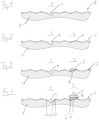
- Figures 1 to 8 Individual steps of the method according to the invention are shown by way of example using a cross-sectional view of a surface 2 of a component 1.
- the surface 2 of the component 1 is structured and has both depressions and elevations.
- a comparison surface 5 is first determined, the surface structure of which corresponds to the surface structure of the partial surface 3 in the original state and thus in the state to be restored.
- a suitable comparison surface 5 is located directly on the component 1, which also has the damaged area 4.
- a comparison surface 5 it is also possible for a comparison surface 5 to be used on a component (not shown) that is identical to component 1 but not damaged, whereby the comparison surface 5 can be selected at the location on the identical component that is comparable to the partial surface 3.
- a release agent 6 is applied, which can be removed at a later time without leaving any residue ( Figure 2 ).
- a matrix material 7 which can be cured by irradiation with UV light and is transparent when cured is applied to the area of the comparison surface 5 ( Figure 3 ), which can later be removed from surface 2 in the hardened state without leaving any residue or causing any damage.
- the pressing stamp 8 For hardening, pressure is applied to the matrix material 7 using the pressing stamp 8.
- the pressing stamp 8 On the surface facing the matrix material 7, the pressing stamp 8 has a flat UV light source 9 (e.g. made of LED tiles) or a light exit window suitable for an internal UV light source. While the matrix material 7 is pressed onto the surface 2, electromagnetic irradiation with UV light takes place at the same time, so that the matrix material 7 solidifies into a transparent matrix 7 ⁇ (cf. Figure 5 ).
- the damaged area 4 is prepared for repair by - in addition to cleaning the damaged area 4 - enlarging the damaged area 4 by creating a small transverse hole 12, for example by drilling, in such a way that an undercut is created, via which the material ultimately filling the damaged area 4 is secured not only by material bonding in the damaged area 4, but also by form bonding.
- a release agent 10 is again applied, which is intended to prevent the hardenable material 11 subsequently filled into the damaged area 4 from adhering to areas of the surface 2 that are actually not damaged.
- the damaged area 4 including the transverse hole 12 is filled with material 11 that can be cured by electromagnetic radiation in the UV range.
- the material 11 - e.g. an epoxy resin - is selected such that when cured it takes on a color corresponding to the color of the surface 2.
- the previously produced transparent matrix 7' is then removed from the comparison surface 5 and placed on the hardenable material 11. Due to the transparency of the matrix 7', it can be aligned on the partial surface 3 in such a way that the negative form of the comparison surface 5 on its underside corresponds to the negative of the desired later form of the surface 2 in the partial surface 3 ( Figure 6 ). This is important so that the later residual visibility of the repaired damaged area 4 is as low as possible. Any excess material 11" can then exit from the side under the matrix 7' and - thanks to the release agent 10 - be removed without leaving any residue.
- the die 7' is then pressed onto the material 11 using the previously used pressing die 8 ( Figure 7 ), whereby it is pressed against the surface in the damaged area 4.
- the same contact pressure is exerted on the matrix 7 ⁇ as in the Figure 4
- the UV-curable material 11' is converted into cured material 11 ⁇ by means of electromagnetic radiation emanating from the UV light source 9 and passing through the transparent matrix 7 ⁇ .
- the pressing stamp 8 and the die 7 ⁇ can be removed and the surface 2 of the component 1 is repaired in the partial area 3 with the original damaged area 4 ( Figure 8 ). If necessary, the hardened material 11' can then be further processed with a top coat in order to achieve, for example, a gloss adapted to the remaining surface 2.
Landscapes
- Engineering & Computer Science (AREA)
- Mechanical Engineering (AREA)
- Physics & Mathematics (AREA)
- Health & Medical Sciences (AREA)
- Electromagnetism (AREA)
- Toxicology (AREA)
- Oral & Maxillofacial Surgery (AREA)
- Thermal Sciences (AREA)
- Application Of Or Painting With Fluid Materials (AREA)
- Heating, Cooling, Or Curing Plastics Or The Like In General (AREA)
Description
- Die Erfindung betrifft ein Verfahren zur Instandsetzung von strukturierten Oberflächen eines Bauteils.
- Bei industriell hergestellten Bauteilen können solche Oberflächen, die im Verwendungszustand einem Nutzer zugewandt sind, oberflächlich strukturiert sein, um so dem Nutzer einen gewünschten optischen und/oder haptischen Eindruck zu vermitteln. Insbesondere ist es möglich, durch strukturierte Oberflächen zusammen mit geeigneter Farbgebung den Eindruck eines anderen Materials als das tatsächlich für das Bauteil verwendete Material zu erzeugen. So lassen sich bspw. Holz- oder Steinoberflächen durch Kunststoffe besonders naturgetreu nachempfinden, wenn die Holzmaserung bzw. die Steinrauheit auf der Oberfläche des Bauteils nachgebildet ist. Beispiele für entsprechende Bauteile mit strukturierten Oberflächen sind sog. Designfußbodenbeläge aus Polyvinylchlorid (PVC), die Stein-, Fließen- oder Holzoptik aufweisen können, Küchenarbeitsplatten aus Kunstharz mit Steinoptik oder Kunststofffurniere, wie sie bei Bauteilen für die Innenausstattung von Flugzeugen verwendet werden, die eine Holzoptik mitsamt entsprechender Maserung aufweisen.
- Kommt es zu Beschädigungen der strukturierten Oberflächen eines Bauteils, bei dem ein Teil der strukturierten Oberfläche ausgelöst ist, bspw. aufgrund eines Abplatzens der Oberflächenschicht infolge eines Stoßes, besteht regelmäßig der Wunsch, die Oberfläche des Bauteils wieder so instand zu setzen, dass keine oder nur eine geringe Restsichtbarkeit der reparierten Stelle vorhanden ist. Dies gilt insbesondere für solche Bauteiloberflächen, bei denen ein Austausch des gesamten Bauteils nicht oder nur sehr aufwendig möglich ist.
- Eine Instandsetzung strukturierter Oberflächen mit einer geringen Restsichtbarkeit im derzeitigen Stand der Technik ist praktisch nur in sehr aufwendiger, handwerklich anspruchsvoller Handarbeit möglich, die folglich sehr kostenintensiv ist.
- Das Dokument
US5246642 A1 stellt den nächstliegenden Stand der Technik dar und offenbart ein Verfahren zur Reparatur von strukturierten Oberflächen, insbesondere von Fiberglas-Schiffshüllen. - Die im Stand der Technik ebenfalls angewandten Prägetechnik, bei der ein in die Fehlstelle einer Oberfläche eingefülltes Material mithilfe eines Prägestempels mit einer Oberflächenstrukturierung versehen und während der Anlage des Prägestempels ausgehärtet wird, eignet sich - wenn überhaupt - nur für richtungsunabhängig, kleinteilige, zufällige Oberflächenstrukturen. Insbesondere bei richtungsabhängigen Oberflächenstrukturen - wie bspw. der Imitation einer Holzmaserung - treten jedoch regelmäßig Fehlprägungen auf, sodass die so reparierte Fehlstelle dauerhaft und deutlich sichtbar bleibt. Außerdem
- sind die für ein solches Reparaturverfahren verwendbaren Materialien nicht für jeden Anwendungszweck geeignet, da sie bspw. nicht ausreichend thermobeständig sind oder die Brandschutzanforderungen nicht erfüllen.
- Aufgabe der vorliegenden Erfindung ist es ein Verfahren zur Instandsetzung von strukturierten Oberflächen eines Bauteils zu schaffen, bei dem die Nachteile aus dem Stand der Technik nicht mehr oder nur noch im verminderten Umfang auftreten. Gelöst wird diese Aufgabe durch ein Verfahren gemäß dem Hauptanspruch. Vorteilhafte Weiterbildungen sind Gegenstand der abhängigen Ansprüche.
- Demnach betrifft die Erfindung ein Verfahren zur Instandsetzung von strukturierten Oberflächen eines Bauteils mit einer Schadstelle umfassend eine Materialauslösung in einer Teilfläche der Oberfläche, mit den Schritten:
- a) Ermitteln einer Vergleichsfläche zur Teilfläche mit wenigstens vergleichbarer Oberflächenstruktur;
- b) Aufbringen von aushärtbarem und wenigstens im ausgehärteten Zustand transparenten Matrizenmaterial auf die Vergleichsfläche;
- c) Während das Matrizenmaterial an die Vergleichsfläche mit einem Anpressdruck angedrückt wird: Aushärten des Matrizenmaterials zu einer von der Vergleichsfläche rückstandsfrei ablösbaren, transparenten Matrize mit der Negativform der Oberflächenstruktur der Vergleichsfläche;
- d) Auffüllen der Schadstelle der Teilfläche mit elektromagnetischer Bestrahlung aushärtbarem Material;
- e) Auflegen der Matrize auf das aushärtbare Material in der Schadstelle in einer Ausrichtung der Negativform der transparenten Matrize entsprechend der gewünschten Oberflächenstruktur an der Schadstelle;
- f) Während die Matrize auf die Schadstelle mit einem Anpressdruck angedrückt wird: Bestrahlen des aushärtbarem Materials mit elektromagnetischer Bestrahlung durch die transparente Matrize bis das Material ausgehärtet ist; und
- g) Rückstandsfreies Entfernen der Matrize von dem ausgehärteten Material an der Schadstelle.
- Das erfindungsgemäße Verfahren ermöglicht die Instandsetzung von strukturierten Oberflächen eines Bauteils, bei der ein Teil des die Oberfläche des Bauteils bildenden Materials ausgelöst ist. Bei einer entsprechenden Schadstelle kann es sich bspw. um Abplatzung, Stoßbeschädigungen oder tiefe Kratzer handeln. Es hat sich gezeigt, dass eine gemäß dem erfindungsgemäßen Verfahren reparierten Schadstelle im Hinblick auf die Oberflächenstruktur regelmäßig kaum sichtbar ist und die auch bei Bedarf erhöhten Anforderungen, bspw. hinsichtlich thermischer oder mechanischer Belastungen oder dem Brandschutz, gerecht werden kann. Beide Vorteile lassen sich durch die erfindungsgemäß vorgesehene Verwendung einer transparenten Matrize zur Ausformung der Struktur auf der Oberfläche im Bereich der Schadstelle realisieren: Aufgrund der Transparenz der Matrize kann diese zum einen bei ihrer Verwendung genau ausgerichtet werden, sodass Fehlprägungen effektiv vermieden werden können, zum anderen ist es aufgrund der Transparenz möglich, mit elektromagnetischer Bestrahlung aushärtbares Material zur Auffüllung der Schadstelle zu verwenden, welches durch die Matrize hindurch zum Aushärten geeignet bestrahlt werden kann.
- Um die Restsichtbarkeit einer instandgesetzten Schadstelle bestmöglich zu reduzieren, ist erfindungsgemäß außerdem vorgesehen, die für die spätere Instandsetzung verwendete Matrize für die instand zu setzende Schadstelle anhand einer Vergleichsfläche - also einer Fläche, die auch in Hinblick auf die Oberflächenstruktur der Teilfläche mit der Schadstelle vergleichbar, vorzugsweise identisch ist - erstellt wird, um so eine bestmögliche Anpassung der Oberflächenstruktur im Bereich der Schadstelle zu erreichen. Die Vergleichsfläche kann dabei auf demselben Bauteil zu finden sein, an dem sich auch die instand zu setzende Schadstelle befindet. Dies gilt insbesondere für sich wiederholende Oberflächenstrukturen. Alternativ ist es auch möglich, die Vergleichsfläche auf einem beschädigungsfreien Bauteil aufzufinden, welches zu dem instand zu setzenden Bauteil identisch ist. In diesem Fall kann die Vergleichsfläche auf dem beschädigungsfreien Bauteil identisch zur die Schadstelle aufweisenden Teilfläche gewählt werden. In andere Worten kann die Matrize also an genau der Stelle des beschädigungsfreien Bauteils hergestellt werden, an der sich bei dem instand zu setzenden Bauteil die Schadstelle wiederfindet. Insbesondere bei industriell in Serie hergestellten Bauteilen ist eine solche Vorgehensweise möglich.
- Nach dem Ermitteln einer geeigneten Vergleichsfläche wird aushärtbares und wenigstens im ausgehärteten Zustand transparentes Matrizenmaterial auf die gesamte Vergleichsfläche aufgebracht. Bspw. kann es sich beim Matrizenmaterial um transparentes Harz handeln. Bei dem Harz kann es sich bspw. um ein Epoxid-Harz, ein Acryl-Harz oder ein Polyurethan-Harz handeln. Wesentlich ist lediglich, dass das Harz im ausgehärteten Zustand transparent und außerdem ausreichen formstabil ist, um später formgebend für das aushärtbare Material zu sein. Um das spätere rückstandsfreie Ablösen der ausgehärteten Matrize sicher zu gewährleisten, kann bei Bedarf vor dem Aufbringen des Matrizenmaterials ein geeignetes Trennmittel auf die Vergleichsfläche aufgebracht werden.
- Das aushärtbare Matrizenmaterial wird dann mit einem vorgegebenen oder frei gewählten Anpressdruck an die Vergleichsfläche angedrückt und dann ausgehärtet. Das Aushärten kann in Abhängigkeit der Materialeigenschaften des Matrizenmaterials erfolgen und bei Bedarf bspw. thermisch oder durch elektromagnetische Bestrahlung, z. B. durch (UV-)Licht, angeregt werden. Auch ist möglich, dass das Matrizenmaterial aufgrund einer chemischen Reaktion, bspw. von zwei kurz vor Anwendung vermischten Komponenten, aushärtet.
- Nach erfolgtem Aushärten liegt eine rückstandsfrei ablösbare, transparente Matrize mit der Negativform der Oberflächenstruktur der Vergleichsfläche vor.
- Nach oder parallel zur Erstellung der transparenten Matrize wird die eigentliche Schadstelle in der Teilfläche des instand zu setzenden Bauteils mit Material aufgefüllt, welches durch elektromagnetische Strahlung, also insbesondere sichtbares Licht oder UV-Strahlung, ausgehärtet werden kann. Dabei kann die Schadstelle vor dem Auffüllen mit aushärtbarem Material bei Bedarf vergrößert werden, um die Kontaktfläche zwischen dem fraglichen Material und dem Bauteil zu vergrößern. Auch ist es möglich, bei Bedarf einen Hinterschnitt einzubringen, sodass die spätere Verbindung zwischen dem Material und dem Bauteil nicht nur einen Stoffschluss, sondern auch einen Formschluss umfasst.
- Bei dem aushärtbaren Material kann es sich bevorzugt um Harz, bspw. auf Basis von Epoxid, Acrylat oder Polyurethane, handeln. Das Harz kann dabei so gewählt werden, dass es im ausgehärteten Zustand die gewünschten oder vorgeschriebenen Eigenschaften, bspw. hinsichtlich thermischer oder mechanischer Belastungen oder dem Brandschutz, aufweist. Selbstverständlich ist bevorzugt, dass der Farbton des aushärtbaren Materials entsprechend dem Farbton der Oberfläche an der Schadstelle gewählt ist. Dabei ist insbesondere der Farbton des Materials im ausgehärteten Zustand relevant, um eine möglichst geringe Restsichtbarkeit der instandgesetzten Schadstelle zu erreichen.
- Nach Auffüllen der Schadstelle der Teilfläche mit elektromagnetischer Bestrahlung aushärtbarem Material wird anschließend die zuvor erstellte Matrize auf das aushärtbare Material in der Schadstelle in einer Ausrichtung der Negativform der transparenten Matrize entsprechend der gewünschten Oberflächenstruktur an der Schadstelle aufgelegt. Da die Matrize gemäß dem erfindungsgemäßen Verfahren transparent ist, kann die korrekte Ausrichtung der Matrize unmittelbar überprüft werden.
- Die korrekte Ausrichtung in allen drei Achsen ist dabei wesentlich, um die Restsichtbarkeit einer instandgesetzten Schadstelle soweit wie möglich zu reduzieren.
- Die Matrize wird dann auf die Schadstelle mit einem Anpressdruck angedrückt. Dabei ist Anpressdruck vorzugsweise gleich dem Anpressdruck beim Aushärten des Matrizenmaterials zur Erstellung der Matrize. Zum Anpressen kann bspw. auf den Anpressstempel, der bereits beim Aushärten des Matrizenmaterials verwendet wurde, zurückgegriffen werden.
- Ist die Matrize in ihrem Umriss nicht an den Umriss der Schadstelle, bspw. durch entsprechende Nachbearbeitung, angepasst, sodass ggf. überschüssiges aushärtbares Material aus der Schadstelle seitlich an der Matrize vorbei austreten kann, kann die Schadstelle und/oder die Matrize mit einem Auslass für überschüssiges aushärtbares Material versehen werden. Indem ggf. überschüssiges Material austreten kann, ist gewährleistet, dass die spätere Oberfläche im Bereich der Schadstelle mit der umliegenden Teilfläche bündig ist.
- Um zu vermeiden, dass evtl. austretendes Material auf der die Schadstelle umgebenden Teilfläche anhaftet, kann vor Auffüllen der Schadstelle mit aushärtbarem Material die Teilfläche um die Schadstelle mit einem Trennmittel versehen werden.
- Wird die Matrize wie beschrieben in der zuvor überprüften Lage an das aushärtbare Material angedrückt, kann es durch die transparente Matrize hindurch elektromagnetisch, bspw. mit Licht im sichtbaren und/oder UV-Bereich, in einer für das Aushärten geeigneten Wellenlänge bestrahlt werden, bis es vollständig ausgehärtet ist.
- Wird anschließend die Matrize von dem ausgehärteten Material an der Schadstelle rückstandsfrei entfernt, ist die Instandsetzung der strukturierten Oberfläche in vielen Fällen bereits vollständig abgeschlossen. Lediglich in Fällen, in denen bspw. ein besonderer Oberflächenglanz erforderlich ist, um die Restsichtbarkeit weiter zu reduzieren, kann das ausgehärtete Material nach Entfernen der Matrize bei Bedarf mit einem Überzugslack nachbearbeitet werden.
- Es hat sich gezeigt, dass mit dem erfindungsgemäßen Verfahren strukturierten Oberflächen eines Bauteils mit einer Schadstelle umfassend eine Materialauslösung in einer Teilfläche der Oberfläche effizient und kostengünstig instand gesetzt werden können, ohne dass die reparierte Schadstelle im Nachhinein noch unmittelbar erkennbar ist.
- Die Erfindung wird nun anhand eines Ausführungsbeispiels unter Bezugnahme auf die beigefügten Zeichnungen beispielhaft beschrieben. Es zeigen:
- Figuren 1-8:
- schematische Darstellung einzelner Zwischenschritte des erfindungsgemäßen Verfahrens.
- In
Figuren 1 bis 8 sind exemplarisch einzelne Schritte des erfindungsgemäßen Verfahrens anhand einer im Schnitt dargestellten Oberfläche 2 eines Bauteils 1 gezeigt. Die Oberfläche 2 des Bauteils 1 ist strukturiert und weist sowohl Vertiefungen als auch Erhebungen auf. - Im in
Figur 1 gezeigten Ausgangszustand befindet sich in einer Teilfläche 3 der Oberfläche 2 eine Schadstelle 4, in der aufgrund eines Stoßes mit einem spitzen Gegenstand eine Materialauslösung vorliegt. - Um die strukturierte Oberfläche 2 wieder instand zu setzen, wird zunächst eine Vergleichsfläche 5 ermittelt, deren Oberflächenstruktur mit der Oberflächenstruktur der Teilfläche 3 im Original- und somit im wiederherzustellenden Zustand übereinstimmt. Im vorliegenden Beispiel befindet sich eine geeignete Vergleichsfläche 5 unmittelbar auf dem Bauteil 1, welches auch die Schadstelle 4 aufweist. Es ist aber auch möglich, dass eine Vergleichsfläche 5 auf einem zum Bauteil 1 identischen, jedoch nicht beschädigten Bauteil (nicht dargestellt) verwendet wird, wobei die Vergleichsfläche 5 an der zur Teilfläche 3 vergleichbaren Stelle auf dem identischen Bauteil gewählt werden kann.
- Im Bereich der Vergleichsfläche 5 wird ein Trennmittel 6 aufgebracht, welches zu einem späteren Zeitpunkt wieder rückstandslos entfernt werden kann (
Figur 2 ). - Anschließend wird im Bereich der Vergleichsfläche 5 ein durch Bestrahlung mit UV-Licht aushärtbares und im ausgehärteten Zustand transparentes Matrizenmaterial 7 aufgebracht (
Figur 3 ), welches sich später im ausgehärteten Zustand rückstands- und zerstörungsfrei von der Oberfläche 2 ablösen lässt. - Zum Aushärten wird auf das Matrizenmaterial 7 mithilfe des Anpressstempels 8 ein Anpressdruck ausgeübt. An der dem Matrizenmaterial 7 zugewandten Fläche weist der Anpressstempel 8 dabei eine flächige (bspw. aus LED-Kacheln gebildete) UV-Lichtquelle 9 oder ein für eine innen liegende UV-Lichtquelle geeignetes Lichtaustrittsfenster auf. Während das Matrizenmaterial 7 also an die Oberfläche 2 angedrückt wird, erfolgt gleichzeitig eine elektromagnetische Bestrahlung mit UV-Licht, sodass das Matrizenmaterial 7 zu einer transparenten Matrize 7` erstarrt (vgl.
Figur 5 ). - Parallel dazu wird die Schadstelle 4 zur Instandsetzung vorbereitet, indem - neben einer Reinigung der Schadstelle 4 - die Schadstelle 4 durch die Schaffung eines kleinen Querloches 12 bspw. durch Bohren derart vergrößert wird, dass ein Hinterschnitt entsteht, über den das die Schadstelle 4 letztendlich auffüllende Material nicht nur per Stoffschluss in der Schadstelle 4, sondern auch per Formschluss gesichert wird.
- In dem Bereich der Teilfläche 3 um die eigentliche Schadstelle, wird erneut ein Trennmittel 10 aufgebracht, über welches verhindert werden soll, dass das nachfolgend in die Schadstelle 4 eingefüllte aushärtbare Material 11 in Bereichen der Oberfläche 2 anhaftet, die tatsächlich nicht beschädigt sind.
- Wie in
Figur 5 gezeigt, wird die Schadstelle 4 inkl. des Querloches 12 mit durch elektromagnetische Bestrahlung im UV-Bereich aushärtbarem Material 11 aufgefüllt. Das Material 11 - bspw. ein Epoxidharz - ist dabei so gewählt, dass es im ausgehärteten Zustand einen Farbton entsprechend dem Farbton der Oberfläche 2 annimmt. - Anschließend wird die zuvor hergestellte transparente Matrize 7' von der Vergleichsfläche 5 gelöst und auf das aushärtbare Material 11 aufgelegt. Aufgrund der Transparenz der Matrize 7` kann diese derart auf der Teilfläche 3 ausgerichtet werden, dass die Negativform der Vergleichsfläche 5 auf ihrer Unterseite dem Negativ der gewünschten späteren Form der Oberfläche 2 in der Teilfläche 3 entspricht (
Figur 6 ). Dies ist wesentlich, damit die spätere Restsichtbarkeit der instandgesetzten Schadstelle 4 so gering wie möglich ist. Evtl. überschüssiges Material 11" kann dabei seitlich unter der Matrize 7` austreten und - aufgrund des Trennmittels 10 - rückstandsfrei entfernt werden. - Anschließend wird die Matrize 7' mit dem bereits zuvor verwendeten Anpressstempels 8 auf das Material 11 gedrückt (
Figur 7 ), wodurch dieses an die Oberfläche in der Schadstelle 4 angedrückt wird. Dabei wird derselbe Anpressdruck auf die Matrize 7` ausgeübt, wie bei dem inFigur 4 gezeigten Schritt. Währenddessen wird das UV-aushärtbare Material 11' mithilfe von der UV-Lichtquelle 9 ausgehenden und durch die transparente Matrize 7` hindurchtretender elektromagnetischer Strahlung zu ausgehärtetem Material 11`. - Nach vollständigem Aushärten des Materials 11' kann der Anpressstempels 8 und die Matrize 7` entfernt werden und die Oberfläche 2 des Bauteils 1 ist in der Teilfläche 3 mit der ursprünglichen Schadstelle 4 instandgesetzt (
Figur 8 ). Sofern erforderlich, kann das ausgehärtete Material 11' anschließend noch mit einem Überzugslack nachbearbeitet werden, um bspw. einen an die übrige Oberfläche 2 angepassten Glanz zu erreichen.
Claims (8)
- Verfahren zur Instandsetzung von strukturierten Oberflächen (2) eines Bauteils (1) mit einer Schadstelle (4) umfassend eine Materialauslösung in einer Teilfläche (3) der Oberfläche (2), mit den Schritten:a) Ermitteln einer Vergleichsfläche (5) zur Teilfläche (3) mit wenigstens vergleichbarer Oberflächenstruktur;b) Aufbringen von aushärtbarem und wenigstens im ausgehärteten Zustand transparenten Matrizenmaterial (7) auf die Vergleichsfläche (5);c) Während das Matrizenmaterial (7) an die Vergleichsfläche (5) mit einem Anpressdruck angedrückt wird: Aushärten des Matrizenmaterials (7) zu einer von der Vergleichsfläche (5) rückstandsfrei ablösbaren, transparenten Matrize (7') mit der Negativform der Oberflächenstruktur der Vergleichsfläche (5);d) Auffüllen der Schadstelle (4) der Teilfläche (3) mit elektromagnetischer Bestrahlung aushärtbarem Material (11) ;e) Auflegen der Matrize (7') auf das aushärtbare Material (11) in der Schadstelle (4) in einer Ausrichtung der Negativform der transparenten Matrize (7') entsprechend der gewünschten Oberflächenstruktur an der Schadstelle (4) ;f) Während die Matrize (7') auf die Schadstelle (4) mit einem Anpressdruck angedrückt wird: Bestrahlen des aushärtbaren Materials (11) mit elektromagnetischer Bestrahlung durch die transparente Matrize (7') bis das Material (11) ausgehärtet ist; undg) Rückstandsfreies Entfernen der Matrize (7') von dem ausgehärteten Material (11`) an der Schadstelle (4),wobei der Anpressdruck in den Schritten c) und f) gleich ist.
- Verfahren nach Anspruch 1,
dadurch gekennzeichnet, dass
die Vergleichsfläche (5) auf dem Bauteil (1) mit der instandzusetzenden Schadstelle (4) oder auf einem identischen, nicht beschädigtem Bauteil gewählt wird. - Verfahren nach einem der vorhergehenden Ansprüche,
dadurch gekennzeichnet, dass
die Schadstelle (4) und/oder die Matrize (7') mit einem Auslass für überschüssiges aushärtbares Material (11) versehen ist. - Verfahren nach einem der vorhergehenden Ansprüche,
dadurch gekennzeichnet, dass
die Schadstelle (4) vor Auffüllen mit aushärtbarem Material (11) durch Materialabtrag vergrößert wird. - Verfahren nach einem der vorhergehenden Ansprüche,
dadurch gekennzeichnet, dass
vor Auffüllen der Schadstelle (4) mit aushärtbarem Material (11) die Teilfläche (3) um die Schadstelle (4) mit einem Trennmittel (10) zur Vermeidung des Anhaften des aushärtbaren Materials (11) daran versehen wird. - Verfahren nach einem der vorhergehenden Ansprüche,
dadurch gekennzeichnet, dass
das aushärtbare Material (11) ein, vorzugsweise durch UV-Licht, aushärtbares Harz ist. - Verfahren nach einem der vorhergehenden Ansprüche,
dadurch gekennzeichnet, dass
der Farbton des aushärtbaren Materials (11) entsprechend dem Farbton der Oberfläche (2) an der Schadstelle (4) gewählt ist. - Verfahren nach einem der vorhergehenden Ansprüche,
dadurch gekennzeichnet, dass
das ausgehärtete Material (11`) nach Entfernen der Matrize (7') mit einem Überzugslack nachbearbeitet wird.
Applications Claiming Priority (2)
| Application Number | Priority Date | Filing Date | Title |
|---|---|---|---|
| DE102019122639.2A DE102019122639A1 (de) | 2019-08-22 | 2019-08-22 | Verfahren zur Instandsetzung von strukturierten Oberflächen |
| PCT/EP2020/073170 WO2021032771A1 (de) | 2019-08-22 | 2020-08-19 | Verfahren zur instandsetzung von strukturierten oberflächen |
Publications (2)
| Publication Number | Publication Date |
|---|---|
| EP4017715A1 EP4017715A1 (de) | 2022-06-29 |
| EP4017715B1 true EP4017715B1 (de) | 2024-08-07 |
Family
ID=72178522
Family Applications (1)
| Application Number | Title | Priority Date | Filing Date |
|---|---|---|---|
| EP20760430.7A Active EP4017715B1 (de) | 2019-08-22 | 2020-08-19 | Verfahren zur instandsetzung von strukturierten oberflächen |
Country Status (6)
| Country | Link |
|---|---|
| US (1) | US12115743B2 (de) |
| EP (1) | EP4017715B1 (de) |
| CN (1) | CN114585502A (de) |
| CA (1) | CA3148551A1 (de) |
| DE (1) | DE102019122639A1 (de) |
| WO (1) | WO2021032771A1 (de) |
Families Citing this family (1)
| Publication number | Priority date | Publication date | Assignee | Title |
|---|---|---|---|---|
| CN116673689A (zh) * | 2023-05-30 | 2023-09-01 | 华能海南发电股份有限公司东方电厂 | 对异形部件损伤区域修复的方法 |
Family Cites Families (16)
| Publication number | Priority date | Publication date | Assignee | Title |
|---|---|---|---|---|
| GB1386691A (en) * | 1972-04-10 | 1975-03-12 | Vinylize Systems Europ Ltd | Processes for repairing damaged sheet materials |
| US4086113A (en) * | 1976-08-11 | 1978-04-25 | Cataffo Herman R | Method and means for repairing damaged vinyl sheets |
| US5462702A (en) * | 1992-02-04 | 1995-10-31 | Slaughter, Jr.; Gibbs M. | Method for resurfacing fiberglass boat hulls |
| US5626802A (en) * | 1992-02-04 | 1997-05-06 | Slaughter, Jr.; Gibbs M. | Apparatus and method for resurfacing fiberglass boat hulls and other surfaces |
| US5246642A (en) | 1992-02-04 | 1993-09-21 | Slaughter Jr Gibbs M | Method for resurfacing fiberglass boat hulls |
| US5399373A (en) * | 1993-09-02 | 1995-03-21 | Mrozinski; John B. | Processes for repairing articles having wood appearance formed from synthetic resins |
| US6685971B2 (en) | 2001-06-28 | 2004-02-03 | Rongxiang Xu | Method and composition for repairing and promoting regeneration of mucosal tissue in the gastrointestinal tract |
| JP4611669B2 (ja) * | 2004-06-17 | 2011-01-12 | 株式会社ハウステック | 微細凹凸を設けた成形品の補修方法 |
| EP1683627A1 (de) * | 2005-01-25 | 2006-07-26 | Saab Ab | Verfahren und Vorrichtung zum Reparieren eines Verbundgegenstandes |
| CN103785988B (zh) | 2012-11-02 | 2016-09-21 | 深圳市百安百科技有限公司 | 设备和零件缺损还原修复的方法 |
| US9688032B2 (en) | 2013-07-01 | 2017-06-27 | GM Global Technology Operations LLC | Thermoplastic component repair |
| CN107110190A (zh) * | 2014-12-24 | 2017-08-29 | 3M创新有限公司 | 填充已填充的密封帽中空隙的方法 |
| US10695993B2 (en) * | 2016-01-15 | 2020-06-30 | GM Global Technology Operations LLC | In-situ polymerization of polyamides for composite part repair |
| US10589477B2 (en) * | 2016-05-02 | 2020-03-17 | GM Global Technology Operations LLC | Cosmetic repair of a thermoplastic carbon fiber composite |
| US11084233B2 (en) | 2016-06-09 | 2021-08-10 | Bridgestone Corporation | Tire repair method |
| CA3038249A1 (en) * | 2016-09-27 | 2018-04-05 | Bombardier Inc. | Method for repairing a composite stringer with a composite repair cap |
-
2019
- 2019-08-22 DE DE102019122639.2A patent/DE102019122639A1/de not_active Ceased
-
2020
- 2020-08-19 US US17/636,907 patent/US12115743B2/en active Active
- 2020-08-19 CN CN202080073717.2A patent/CN114585502A/zh active Pending
- 2020-08-19 CA CA3148551A patent/CA3148551A1/en active Pending
- 2020-08-19 WO PCT/EP2020/073170 patent/WO2021032771A1/de not_active Ceased
- 2020-08-19 EP EP20760430.7A patent/EP4017715B1/de active Active
Also Published As
| Publication number | Publication date |
|---|---|
| CA3148551A1 (en) | 2021-02-25 |
| CN114585502A (zh) | 2022-06-03 |
| DE102019122639A1 (de) | 2021-02-25 |
| EP4017715A1 (de) | 2022-06-29 |
| US20220355557A1 (en) | 2022-11-10 |
| US12115743B2 (en) | 2024-10-15 |
| WO2021032771A1 (de) | 2021-02-25 |
Similar Documents
| Publication | Publication Date | Title |
|---|---|---|
| EP1239975B1 (de) | Verfahren und vorrichtung zur oberflächenbeschichtung eines innenausbauteiles für kraftfahrzeuge | |
| DE102004022606A1 (de) | Verfahren zur Herstellung eines dreidimensionalen Objekts mit verbesserter Trennung ausgehärteter Materialschichten von einer Bauebene | |
| EP2857221A1 (de) | Paneel mit supermatter Oberfläche | |
| DE102017101981A1 (de) | Verfahren zum Herstellen eines Dekores | |
| EP2050514B1 (de) | Verfahren und Vorrichtung zum Herstellen einer strukturierten Oberfläche einer lackierten Werkstoffplatte | |
| EP3613573A1 (de) | Verkleidungsbauteil zum verkleiden eines innenraums eines personentransportmittels sowie verfahren zum herstellen eines derartigen verkleidungsbauteils | |
| EP1916080A2 (de) | Verfahren zur Formgestaltung von Betonsteinen und/oder Betonplatten | |
| DE102020103127A1 (de) | Reparatursystem und verfahren zur reparatur eines substrats | |
| DE102016120421A1 (de) | Verfahren zum Herstellen eines Formteils insbesondere eines als Formteil ausgebildeten Dekorteils und/oder Verkleidungsteils für einen Fahrzeuginnenraum | |
| EP4017715B1 (de) | Verfahren zur instandsetzung von strukturierten oberflächen | |
| DE69923150T2 (de) | Verfahren zur Reparatur einer Fahrzeugkarosserie und Blech zur Durchführung des Verfahrens | |
| DE69318507T2 (de) | Verfahren zur Ausführung von sichtbaren Zuschlagstoffen in Betongegenständen | |
| DE4214335A1 (de) | Verfahren zum Herstellen eines Leichtbauteiles in Platten- oder Quaderform | |
| DE102009041928B4 (de) | Verfahren zur Oberflächenglättung und Vorrichtung zur Flächenkaschierung | |
| EP3892388B1 (de) | Verfahren und vorrichtung zur herstellung einer strukturierten oberfläche eines plattenförmigen materials | |
| DE2721696A1 (de) | Verfahren zur ausbesserung schadhafter platten und vorrichtung zur durchfuehrung des verfahrens | |
| DE102017100691A1 (de) | Dekorteil und Verfahren zur Herstellung eines Dekorteils | |
| DE102019119479B4 (de) | Verfahren zur Herstellung eines Isolierpaneels | |
| DE102022116423B4 (de) | Presswerkzeug und Verfahren zur Herstellung eines Presswerkzeugs | |
| DE3347061C1 (de) | Freitragende Verbundplatte fuer Doppelboeden,Decken oder dergleichen | |
| AT411281B (de) | Verfahren zur sanierung eines bauwerks | |
| DE1220586B (de) | Stempel zum Praegen von Kunststoffoberflaechen mit Holzcharakter und Verfahren zum Herstellen dieses Stempels | |
| DE102013209179A1 (de) | Methode zur Schäftreparatur von Bauteilen | |
| DE102009005805A1 (de) | Verfahren zur Herstellung eines Bauteils als Bauwerkstoff | |
| EP4360848A1 (de) | Verfahren zum aufprägen eines musters auf einen körper, körper und giessanordnung |
Legal Events
| Date | Code | Title | Description |
|---|---|---|---|
| STAA | Information on the status of an ep patent application or granted ep patent |
Free format text: STATUS: UNKNOWN |
|
| STAA | Information on the status of an ep patent application or granted ep patent |
Free format text: STATUS: THE INTERNATIONAL PUBLICATION HAS BEEN MADE |
|
| PUAI | Public reference made under article 153(3) epc to a published international application that has entered the european phase |
Free format text: ORIGINAL CODE: 0009012 |
|
| STAA | Information on the status of an ep patent application or granted ep patent |
Free format text: STATUS: REQUEST FOR EXAMINATION WAS MADE |
|
| 17P | Request for examination filed |
Effective date: 20220302 |
|
| AK | Designated contracting states |
Kind code of ref document: A1 Designated state(s): AL AT BE BG CH CY CZ DE DK EE ES FI FR GB GR HR HU IE IS IT LI LT LU LV MC MK MT NL NO PL PT RO RS SE SI SK SM TR |
|
| DAV | Request for validation of the european patent (deleted) | ||
| DAX | Request for extension of the european patent (deleted) | ||
| P01 | Opt-out of the competence of the unified patent court (upc) registered |
Effective date: 20230516 |
|
| GRAP | Despatch of communication of intention to grant a patent |
Free format text: ORIGINAL CODE: EPIDOSNIGR1 |
|
| STAA | Information on the status of an ep patent application or granted ep patent |
Free format text: STATUS: GRANT OF PATENT IS INTENDED |
|
| INTG | Intention to grant announced |
Effective date: 20240516 |
|
| GRAS | Grant fee paid |
Free format text: ORIGINAL CODE: EPIDOSNIGR3 |
|
| GRAA | (expected) grant |
Free format text: ORIGINAL CODE: 0009210 |
|
| STAA | Information on the status of an ep patent application or granted ep patent |
Free format text: STATUS: THE PATENT HAS BEEN GRANTED |
|
| AK | Designated contracting states |
Kind code of ref document: B1 Designated state(s): AL AT BE BG CH CY CZ DE DK EE ES FI FR GB GR HR HU IE IS IT LI LT LU LV MC MK MT NL NO PL PT RO RS SE SI SK SM TR |
|
| REG | Reference to a national code |
Ref country code: GB Ref legal event code: FG4D Free format text: NOT ENGLISH |
|
| REG | Reference to a national code |
Ref country code: CH Ref legal event code: EP |
|
| REG | Reference to a national code |
Ref country code: IE Ref legal event code: FG4D Free format text: LANGUAGE OF EP DOCUMENT: GERMAN |
|
| REG | Reference to a national code |
Ref country code: DE Ref legal event code: R096 Ref document number: 502020008815 Country of ref document: DE |
|
| REG | Reference to a national code |
Ref country code: NL Ref legal event code: FP |
|
| REG | Reference to a national code |
Ref country code: LT Ref legal event code: MG9D |
|
| PG25 | Lapsed in a contracting state [announced via postgrant information from national office to epo] |
Ref country code: NO Free format text: LAPSE BECAUSE OF FAILURE TO SUBMIT A TRANSLATION OF THE DESCRIPTION OR TO PAY THE FEE WITHIN THE PRESCRIBED TIME-LIMIT Effective date: 20241107 |
|
| PG25 | Lapsed in a contracting state [announced via postgrant information from national office to epo] |
Ref country code: GR Free format text: LAPSE BECAUSE OF FAILURE TO SUBMIT A TRANSLATION OF THE DESCRIPTION OR TO PAY THE FEE WITHIN THE PRESCRIBED TIME-LIMIT Effective date: 20241108 Ref country code: PL Free format text: LAPSE BECAUSE OF FAILURE TO SUBMIT A TRANSLATION OF THE DESCRIPTION OR TO PAY THE FEE WITHIN THE PRESCRIBED TIME-LIMIT Effective date: 20240807 Ref country code: PT Free format text: LAPSE BECAUSE OF FAILURE TO SUBMIT A TRANSLATION OF THE DESCRIPTION OR TO PAY THE FEE WITHIN THE PRESCRIBED TIME-LIMIT Effective date: 20241209 Ref country code: FI Free format text: LAPSE BECAUSE OF FAILURE TO SUBMIT A TRANSLATION OF THE DESCRIPTION OR TO PAY THE FEE WITHIN THE PRESCRIBED TIME-LIMIT Effective date: 20240807 |
|
| PG25 | Lapsed in a contracting state [announced via postgrant information from national office to epo] |
Ref country code: BG Free format text: LAPSE BECAUSE OF FAILURE TO SUBMIT A TRANSLATION OF THE DESCRIPTION OR TO PAY THE FEE WITHIN THE PRESCRIBED TIME-LIMIT Effective date: 20240807 |
|
| PG25 | Lapsed in a contracting state [announced via postgrant information from national office to epo] |
Ref country code: LV Free format text: LAPSE BECAUSE OF FAILURE TO SUBMIT A TRANSLATION OF THE DESCRIPTION OR TO PAY THE FEE WITHIN THE PRESCRIBED TIME-LIMIT Effective date: 20240807 |
|
| PG25 | Lapsed in a contracting state [announced via postgrant information from national office to epo] |
Ref country code: IS Free format text: LAPSE BECAUSE OF FAILURE TO SUBMIT A TRANSLATION OF THE DESCRIPTION OR TO PAY THE FEE WITHIN THE PRESCRIBED TIME-LIMIT Effective date: 20241207 |
|
| PG25 | Lapsed in a contracting state [announced via postgrant information from national office to epo] |
Ref country code: HR Free format text: LAPSE BECAUSE OF FAILURE TO SUBMIT A TRANSLATION OF THE DESCRIPTION OR TO PAY THE FEE WITHIN THE PRESCRIBED TIME-LIMIT Effective date: 20240807 |
|
| PG25 | Lapsed in a contracting state [announced via postgrant information from national office to epo] |
Ref country code: RS Free format text: LAPSE BECAUSE OF FAILURE TO SUBMIT A TRANSLATION OF THE DESCRIPTION OR TO PAY THE FEE WITHIN THE PRESCRIBED TIME-LIMIT Effective date: 20241107 Ref country code: ES Free format text: LAPSE BECAUSE OF FAILURE TO SUBMIT A TRANSLATION OF THE DESCRIPTION OR TO PAY THE FEE WITHIN THE PRESCRIBED TIME-LIMIT Effective date: 20240807 |
|
| PG25 | Lapsed in a contracting state [announced via postgrant information from national office to epo] |
Ref country code: RS Free format text: LAPSE BECAUSE OF FAILURE TO SUBMIT A TRANSLATION OF THE DESCRIPTION OR TO PAY THE FEE WITHIN THE PRESCRIBED TIME-LIMIT Effective date: 20241107 Ref country code: PT Free format text: LAPSE BECAUSE OF FAILURE TO SUBMIT A TRANSLATION OF THE DESCRIPTION OR TO PAY THE FEE WITHIN THE PRESCRIBED TIME-LIMIT Effective date: 20241209 Ref country code: PL Free format text: LAPSE BECAUSE OF FAILURE TO SUBMIT A TRANSLATION OF THE DESCRIPTION OR TO PAY THE FEE WITHIN THE PRESCRIBED TIME-LIMIT Effective date: 20240807 Ref country code: NO Free format text: LAPSE BECAUSE OF FAILURE TO SUBMIT A TRANSLATION OF THE DESCRIPTION OR TO PAY THE FEE WITHIN THE PRESCRIBED TIME-LIMIT Effective date: 20241107 Ref country code: LV Free format text: LAPSE BECAUSE OF FAILURE TO SUBMIT A TRANSLATION OF THE DESCRIPTION OR TO PAY THE FEE WITHIN THE PRESCRIBED TIME-LIMIT Effective date: 20240807 Ref country code: IS Free format text: LAPSE BECAUSE OF FAILURE TO SUBMIT A TRANSLATION OF THE DESCRIPTION OR TO PAY THE FEE WITHIN THE PRESCRIBED TIME-LIMIT Effective date: 20241207 Ref country code: HR Free format text: LAPSE BECAUSE OF FAILURE TO SUBMIT A TRANSLATION OF THE DESCRIPTION OR TO PAY THE FEE WITHIN THE PRESCRIBED TIME-LIMIT Effective date: 20240807 Ref country code: GR Free format text: LAPSE BECAUSE OF FAILURE TO SUBMIT A TRANSLATION OF THE DESCRIPTION OR TO PAY THE FEE WITHIN THE PRESCRIBED TIME-LIMIT Effective date: 20241108 Ref country code: FI Free format text: LAPSE BECAUSE OF FAILURE TO SUBMIT A TRANSLATION OF THE DESCRIPTION OR TO PAY THE FEE WITHIN THE PRESCRIBED TIME-LIMIT Effective date: 20240807 Ref country code: ES Free format text: LAPSE BECAUSE OF FAILURE TO SUBMIT A TRANSLATION OF THE DESCRIPTION OR TO PAY THE FEE WITHIN THE PRESCRIBED TIME-LIMIT Effective date: 20240807 Ref country code: BG Free format text: LAPSE BECAUSE OF FAILURE TO SUBMIT A TRANSLATION OF THE DESCRIPTION OR TO PAY THE FEE WITHIN THE PRESCRIBED TIME-LIMIT Effective date: 20240807 |
|
| PG25 | Lapsed in a contracting state [announced via postgrant information from national office to epo] |
Ref country code: SM Free format text: LAPSE BECAUSE OF FAILURE TO SUBMIT A TRANSLATION OF THE DESCRIPTION OR TO PAY THE FEE WITHIN THE PRESCRIBED TIME-LIMIT Effective date: 20240807 Ref country code: DK Free format text: LAPSE BECAUSE OF FAILURE TO SUBMIT A TRANSLATION OF THE DESCRIPTION OR TO PAY THE FEE WITHIN THE PRESCRIBED TIME-LIMIT Effective date: 20240807 |
|
| PG25 | Lapsed in a contracting state [announced via postgrant information from national office to epo] |
Ref country code: LU Free format text: LAPSE BECAUSE OF NON-PAYMENT OF DUE FEES Effective date: 20240819 |
|
| PG25 | Lapsed in a contracting state [announced via postgrant information from national office to epo] |
Ref country code: EE Free format text: LAPSE BECAUSE OF FAILURE TO SUBMIT A TRANSLATION OF THE DESCRIPTION OR TO PAY THE FEE WITHIN THE PRESCRIBED TIME-LIMIT Effective date: 20240807 |
|
| PG25 | Lapsed in a contracting state [announced via postgrant information from national office to epo] |
Ref country code: CZ Free format text: LAPSE BECAUSE OF FAILURE TO SUBMIT A TRANSLATION OF THE DESCRIPTION OR TO PAY THE FEE WITHIN THE PRESCRIBED TIME-LIMIT Effective date: 20240807 |
|
| PG25 | Lapsed in a contracting state [announced via postgrant information from national office to epo] |
Ref country code: SK Free format text: LAPSE BECAUSE OF FAILURE TO SUBMIT A TRANSLATION OF THE DESCRIPTION OR TO PAY THE FEE WITHIN THE PRESCRIBED TIME-LIMIT Effective date: 20240807 |
|
| REG | Reference to a national code |
Ref country code: DE Ref legal event code: R097 Ref document number: 502020008815 Country of ref document: DE |
|
| PLBE | No opposition filed within time limit |
Free format text: ORIGINAL CODE: 0009261 |
|
| STAA | Information on the status of an ep patent application or granted ep patent |
Free format text: STATUS: NO OPPOSITION FILED WITHIN TIME LIMIT |
|
| REG | Reference to a national code |
Ref country code: BE Ref legal event code: MM Effective date: 20240831 |
|
| PG25 | Lapsed in a contracting state [announced via postgrant information from national office to epo] |
Ref country code: MC Free format text: LAPSE BECAUSE OF FAILURE TO SUBMIT A TRANSLATION OF THE DESCRIPTION OR TO PAY THE FEE WITHIN THE PRESCRIBED TIME-LIMIT Effective date: 20240807 |
|
| PG25 | Lapsed in a contracting state [announced via postgrant information from national office to epo] |
Ref country code: BE Free format text: LAPSE BECAUSE OF NON-PAYMENT OF DUE FEES Effective date: 20240831 |
|
| 26N | No opposition filed |
Effective date: 20250508 |
|
| PG25 | Lapsed in a contracting state [announced via postgrant information from national office to epo] |
Ref country code: IE Free format text: LAPSE BECAUSE OF NON-PAYMENT OF DUE FEES Effective date: 20240819 |
|
| PG25 | Lapsed in a contracting state [announced via postgrant information from national office to epo] |
Ref country code: SE Free format text: LAPSE BECAUSE OF FAILURE TO SUBMIT A TRANSLATION OF THE DESCRIPTION OR TO PAY THE FEE WITHIN THE PRESCRIBED TIME-LIMIT Effective date: 20240807 |
|
| PGFP | Annual fee paid to national office [announced via postgrant information from national office to epo] |
Ref country code: NL Payment date: 20250821 Year of fee payment: 6 |
|
| PGFP | Annual fee paid to national office [announced via postgrant information from national office to epo] |
Ref country code: DE Payment date: 20250819 Year of fee payment: 6 |
|
| PGFP | Annual fee paid to national office [announced via postgrant information from national office to epo] |
Ref country code: GB Payment date: 20250818 Year of fee payment: 6 |
|
| PGFP | Annual fee paid to national office [announced via postgrant information from national office to epo] |
Ref country code: AT Payment date: 20250819 Year of fee payment: 6 Ref country code: FR Payment date: 20250821 Year of fee payment: 6 |
|
| PGFP | Annual fee paid to national office [announced via postgrant information from national office to epo] |
Ref country code: CH Payment date: 20250901 Year of fee payment: 6 |
|
| PG25 | Lapsed in a contracting state [announced via postgrant information from national office to epo] |
Ref country code: RO Free format text: LAPSE BECAUSE OF FAILURE TO SUBMIT A TRANSLATION OF THE DESCRIPTION OR TO PAY THE FEE WITHIN THE PRESCRIBED TIME-LIMIT Effective date: 20240807 |