EP4016727B1 - Antenne und elektronische vorrichtung - Google Patents
Antenne und elektronische vorrichtung Download PDFInfo
- Publication number
- EP4016727B1 EP4016727B1 EP20856523.4A EP20856523A EP4016727B1 EP 4016727 B1 EP4016727 B1 EP 4016727B1 EP 20856523 A EP20856523 A EP 20856523A EP 4016727 B1 EP4016727 B1 EP 4016727B1
- Authority
- EP
- European Patent Office
- Prior art keywords
- antenna
- edge
- wavelength
- antenna body
- electronic device
- Prior art date
- Legal status (The legal status is an assumption and is not a legal conclusion. Google has not performed a legal analysis and makes no representation as to the accuracy of the status listed.)
- Active
Links
Images







Classifications
-
- H—ELECTRICITY
- H01—ELECTRIC ELEMENTS
- H01Q—ANTENNAS, i.e. RADIO AERIALS
- H01Q1/00—Details of, or arrangements associated with, antennas
- H01Q1/36—Structural form of radiating elements, e.g. cone, spiral, umbrella; Particular materials used therewith
-
- H—ELECTRICITY
- H01—ELECTRIC ELEMENTS
- H01Q—ANTENNAS, i.e. RADIO AERIALS
- H01Q1/00—Details of, or arrangements associated with, antennas
- H01Q1/48—Earthing means; Earth screens; Counterpoises
-
- H—ELECTRICITY
- H01—ELECTRIC ELEMENTS
- H01Q—ANTENNAS, i.e. RADIO AERIALS
- H01Q1/00—Details of, or arrangements associated with, antennas
- H01Q1/12—Supports; Mounting means
- H01Q1/22—Supports; Mounting means by structural association with other equipment or articles
- H01Q1/24—Supports; Mounting means by structural association with other equipment or articles with receiving set
- H01Q1/241—Supports; Mounting means by structural association with other equipment or articles with receiving set used in mobile communications, e.g. GSM
- H01Q1/242—Supports; Mounting means by structural association with other equipment or articles with receiving set used in mobile communications, e.g. GSM specially adapted for hand-held use
-
- H—ELECTRICITY
- H01—ELECTRIC ELEMENTS
- H01Q—ANTENNAS, i.e. RADIO AERIALS
- H01Q1/00—Details of, or arrangements associated with, antennas
- H01Q1/12—Supports; Mounting means
- H01Q1/22—Supports; Mounting means by structural association with other equipment or articles
- H01Q1/24—Supports; Mounting means by structural association with other equipment or articles with receiving set
- H01Q1/241—Supports; Mounting means by structural association with other equipment or articles with receiving set used in mobile communications, e.g. GSM
- H01Q1/242—Supports; Mounting means by structural association with other equipment or articles with receiving set used in mobile communications, e.g. GSM specially adapted for hand-held use
- H01Q1/243—Supports; Mounting means by structural association with other equipment or articles with receiving set used in mobile communications, e.g. GSM specially adapted for hand-held use with built-in antennas
-
- H—ELECTRICITY
- H01—ELECTRIC ELEMENTS
- H01Q—ANTENNAS, i.e. RADIO AERIALS
- H01Q1/00—Details of, or arrangements associated with, antennas
- H01Q1/36—Structural form of radiating elements, e.g. cone, spiral, umbrella; Particular materials used therewith
- H01Q1/38—Structural form of radiating elements, e.g. cone, spiral, umbrella; Particular materials used therewith formed by a conductive layer on an insulating support
-
- H—ELECTRICITY
- H01—ELECTRIC ELEMENTS
- H01Q—ANTENNAS, i.e. RADIO AERIALS
- H01Q1/00—Details of, or arrangements associated with, antennas
- H01Q1/44—Details of, or arrangements associated with, antennas using equipment having another main function to serve additionally as an antenna, e.g. means for giving an antenna an aesthetic aspect
- H01Q1/46—Electric supply lines or communication lines
-
- H—ELECTRICITY
- H01—ELECTRIC ELEMENTS
- H01Q—ANTENNAS, i.e. RADIO AERIALS
- H01Q1/00—Details of, or arrangements associated with, antennas
- H01Q1/50—Structural association of antennas with earthing switches, lead-in devices or lightning protectors
-
- H—ELECTRICITY
- H01—ELECTRIC ELEMENTS
- H01Q—ANTENNAS, i.e. RADIO AERIALS
- H01Q25/00—Antennas or antenna systems providing at least two radiating patterns
- H01Q25/04—Multimode antennas
-
- H—ELECTRICITY
- H01—ELECTRIC ELEMENTS
- H01Q—ANTENNAS, i.e. RADIO AERIALS
- H01Q5/00—Arrangements for simultaneous operation of antennas on two or more different wavebands, e.g. dual-band or multi-band arrangements
- H01Q5/10—Resonant antennas
-
- H—ELECTRICITY
- H01—ELECTRIC ELEMENTS
- H01Q—ANTENNAS, i.e. RADIO AERIALS
- H01Q5/00—Arrangements for simultaneous operation of antennas on two or more different wavebands, e.g. dual-band or multi-band arrangements
- H01Q5/20—Arrangements for simultaneous operation of antennas on two or more different wavebands, e.g. dual-band or multi-band arrangements characterised by the operating wavebands
- H01Q5/28—Arrangements for establishing polarisation or beam width over two or more different wavebands
-
- H—ELECTRICITY
- H01—ELECTRIC ELEMENTS
- H01Q—ANTENNAS, i.e. RADIO AERIALS
- H01Q5/00—Arrangements for simultaneous operation of antennas on two or more different wavebands, e.g. dual-band or multi-band arrangements
- H01Q5/30—Arrangements for providing operation on different wavebands
- H01Q5/307—Individual or coupled radiating elements, each element being fed in an unspecified way
- H01Q5/314—Individual or coupled radiating elements, each element being fed in an unspecified way using frequency dependent circuits or components, e.g. trap circuits or capacitors
- H01Q5/328—Individual or coupled radiating elements, each element being fed in an unspecified way using frequency dependent circuits or components, e.g. trap circuits or capacitors between a radiating element and ground
-
- H—ELECTRICITY
- H01—ELECTRIC ELEMENTS
- H01Q—ANTENNAS, i.e. RADIO AERIALS
- H01Q5/00—Arrangements for simultaneous operation of antennas on two or more different wavebands, e.g. dual-band or multi-band arrangements
- H01Q5/30—Arrangements for providing operation on different wavebands
- H01Q5/307—Individual or coupled radiating elements, each element being fed in an unspecified way
- H01Q5/342—Individual or coupled radiating elements, each element being fed in an unspecified way for different propagation modes
- H01Q5/357—Individual or coupled radiating elements, each element being fed in an unspecified way for different propagation modes using a single feed point
-
- H—ELECTRICITY
- H01—ELECTRIC ELEMENTS
- H01Q—ANTENNAS, i.e. RADIO AERIALS
- H01Q9/00—Electrically-short antennas having dimensions not more than twice the operating wavelength and consisting of conductive active radiating elements
- H01Q9/04—Resonant antennas
- H01Q9/06—Details
-
- H—ELECTRICITY
- H01—ELECTRIC ELEMENTS
- H01Q—ANTENNAS, i.e. RADIO AERIALS
- H01Q9/00—Electrically-short antennas having dimensions not more than twice the operating wavelength and consisting of conductive active radiating elements
- H01Q9/04—Resonant antennas
- H01Q9/30—Resonant antennas with feed to end of elongated active element, e.g. unipole
- H01Q9/42—Resonant antennas with feed to end of elongated active element, e.g. unipole with folded element, the folded parts being spaced apart a small fraction of the operating wavelength
Definitions
- This application relates to the field of communications technologies, and in particular, to an antenna and an electronic device that includes the antenna.
- a through-slot in metal is usually used to implement a communication function.
- a plurality of spaced slots are disposed on a conductive frame, and a part between adjacent slots forms an antenna body of an antenna.
- a slot is usually disposed on two opposite edges of a frame of the electronic device, and therefore an antenna mainly generates horizontal mode excitation or vertical mode excitation. Consequently, the horizontal mode excitation and the vertical mode excitation are not balanced.
- the slot on the frame is easily blocked. In this case, the horizontal mode excitation or the vertical mode excitation of the antenna is weakened, causing a death grip.
- EP3451636A1 describes a mobile terminal that includes a metal frame including a base unit and a side unit, a main substrate located on a rear surface of the base unit, a display unit seated on a front surface of the base unit, and feed lines extending from the main substrate, connected to the side unit and supplying power to the side unit.
- the side unit includes a first conductive member including a first part and a second part, a second conductive member including a third part and a fourth part, a third conductive member located between the first and second conductive members, a first slit provided between the first and third conductive members and a second slit provided between the second and third conductive, and a length of the second part is two or more times a length of the first part.
- US2019/260126A1 describes an electronic device including a conductive housing and an antenna.
- the antenna includes an arm formed from a first segment of the housing. A gap separates the first segment from a second segment.
- Respective first and second slots separate an antenna ground from the first and second segments.
- the antenna has a first positive antenna feed terminal on the first segment and a second positive antenna feed terminal on the second segment.
- a transmission line includes a signal conductor having a first branch coupled to the first positive antenna feed terminal and a second branch coupled to the second positive antenna feed terminal.
- a switch is interposed on the second branch for switching the antenna between a first mode in which the second slot is directly fed and a second mode in which the second segment is indirectly fed by the first segment.
- US10389010B2 describes an antenna structure including a metallic member, a feed portion, a ground portion and a radiating portion.
- AU2019100180A4 describes a device including a display and a housing. The housing surrounds the display and has four corners defining portions of an exterior surface of the device. The housing includes a first housing segment defining at least part of a first corner of the four corners and configured to operate as an antenna.
- This application provides an antenna and an electronic device, to resolve a problem that horizontal mode excitation and vertical mode excitation of an antenna are not balanced, so that the antenna still has relatively good antenna radiation performance in a handheld state.
- the invention is defined in the appended claims. Any embodiments described herein that fall outside of the scope of the claims are included for illustrative purposes only.
- this application provides an antenna.
- the antenna includes an L-shaped antenna body.
- the antenna body includes a first section and a second section that intersects with the first section.
- the antenna body includes a feed point and a grounding point that are disposed with an interval.
- the feed point is configured to connect to a radio frequency front end.
- the grounding point is used for grounding.
- the antenna body includes a first end and a second end that are away from each other.
- the first end is an end that is of the first section and that is far away from the second section.
- the second end is an end that is of the second section and that is far away from the first section.
- An electrical length between the feed point and the first end is greater than an electrical length between the feed point and the second end.
- the antenna body generates resonance of quarter of a first wavelength between the feed point and the first end, and the antenna body generates resonance of half of a second wavelength between the first end and the second end.
- the first wavelength is greater than the second wavelength.
- the antenna may be of a frame antenna (namely, an antenna whose antenna body is a frame of an electronic device), an antenna form of a flexible printed circuit (Flexible Printed Circuit, FPC), an antenna form of a laser direct structuring (Laser-Direct-structuring, LDS), or a microstrip disk antenna (Microstrip Disk Antenna, MDA), or the like.
- FPC Flexible Printed Circuit
- LDS laser direct structuring
- MDA microstrip disk antenna
- the antenna body may be of a linear strip structure, and during use, the antenna body is bent to form the L-shaped antenna body.
- the antenna body generates the resonance of quarter of the first wavelength between the feed point and the first end.
- the electrical length between the feed point and the first end is approximately quarter of the first wavelength, so that the antenna body can generate the resonance of quarter of the first wavelength between the feed point and the first end.
- the antenna body generates the resonance of half of the second wavelength between the first end and the second end.
- an electrical length between the first end and the second end is approximately half of the second wavelength, so that the antenna body can generate the resonance of half of the second wavelength between the first end and the second end.
- the first wavelength and the second wavelength are operating wavelengths of signals whose radiation frequencies fall within a same frequency band (for example, B28, B5, or B8) in an LTE standard.
- the first end is an end that is of the first section and that is far away from the second section.
- the first section is located in a horizontal direction or a vertical direction, that is, horizontal mode excitation or vertical mode excitation can be generated based on the resonance that is of quarter of the first wavelength and that is of the antenna.
- the resonance of half of the second wavelength is formed between the first end and the second end, and the antenna body is L-shaped, and therefore mode excitation in a direction perpendicular to the first section and mode excitation in a direction perpendicular to the second section can be generated.
- horizontal mode excitation and vertical mode excitation can be generated, which can assist in enhancing the mode excitation generated based on the resonance of quarter of the first wavelength, so that horizontal mode excitation and vertical mode excitation of the antenna can be relatively balanced. Therefore, the antenna still has relatively good antenna radiation performance in a handheld state.
- the antenna body can generate both the resonance of quarter of the first wavelength and the resonance of half of the second wavelength, and the mode excitation generated based on the resonance of quarter of the first wavelength and mode excitation in the other direction can be enhanced by using the resonance of half of the second wavelength, so that the horizontal mode excitation and the vertical mode excitation of the antenna are relatively balanced.
- the mode excitation means that port excitation is added to the antenna to enable the antenna to generate a different mode.
- the mode excitation is represented by different distribution of characteristic currents generated by excitation on the antenna.
- the mode excitation in a direction perpendicular to the side on which the first end is located is generated based on the resonance that is of quarter of the first wavelength and that is of the antenna, that is, a main flow direction of a characteristic current generated after excitation is added to the antenna ground is perpendicular to the direction of the side on which the first end is located.
- the direction of the side on which the first end is located is the horizontal direction, vertical mode excitation is mainly generated.
- the mode excitation in a direction perpendicular to the first section and the mode excitation in a direction perpendicular to the second section are generated based on the resonance that is of half of the second wavelength and that is of the antenna, that is, a main flow direction of a characteristic current generated after excitation is added to the antenna ground is perpendicular to the direction of the side on which the first end is located and a direction of a side on which the second end is located.
- the first wavelength is greater than the second wavelength, that is, a frequency of the resonance generated between the feed point and the first end is less than a frequency of the resonance generated between the first end and the second end, to avoid generating an efficiency pit when the resonance of quarter of the first wavelength and the resonance of half of the second wavelength are at a same operating frequency band, so that the antenna can have good radiation performance at the operating frequency band.
- a difference between the frequency of the resonance generated between the feed point and the first end and the frequency of the resonance generated between the first end and the second end ranges from 50 MHz to 200 MHz, to implement better compatibility between the resonance of quarter of the first wavelength and the resonance of half of the second wavelength. Therefore, the antenna can have good radiation performance both in free space and in the handheld state.
- the first connection point may be alternatively located on a side that is of the feed point and the grounding point and that is far away from the first end, to change the electrical length between the feed point and the second end and the electrical length between the first end and the second end, so as to change the operating frequency of the resonance of half of the second wavelength.
- the antenna includes a second switching circuit
- a second connection point is further disposed on the antenna body, the feed point and the grounding point are located between the first connection point and the second connection point, one end of the second switching circuit connects to the second connection point, and the other end is grounded, and the second switching circuit is configured to change the electrical length between the feed point and the second end.
- the second switching circuit connects to the second connection point, that is, the second switching circuit connects to the antenna body through the second connection point, to change the electrical length between the feed point and the second end.
- the first switching circuit changes the electrical length between the feed point and the first end, to change the operating frequency of the resonance of quarter of the first wavelength.
- the second switching circuit cooperates with the first switching circuit, to change an electrical length (namely, the electrical length between the first end and the second end) of the antenna body, so as to change the operating frequency of the resonance of half of the second wavelength.
- a position of the first switching circuit and a position of the second switching circuit may be interchanged.
- the first switching circuit includes a first switch and a plurality of different first tuning elements that are grounded, and the first switch connects to the different first tuning elements through switching, to change the electrical length between the feed point and the first end.
- the first switch connects to different first tuning elements through switching, so that different first tuning elements connect to the antenna body.
- the different first tuning elements may be tuning elements of different types, for example, may be capacitors, inductors, or resistors.
- the different first tuning elements may be tuning elements that are of a same type and that differ in specification and size. For example, all the tuning elements are inductors, but the tuning elements have different inductance values.
- Different first tuning elements connect to the antenna body, to change the electrical length between the first end and the second end and the electrical length between the feed point and the first end that are of the antenna body, so as to adjust the operating frequencies of the resonance of quarter of the first wavelength and the resonance of half of the second wavelength that are generated by the antenna body.
- the second switch when the first switch connects to the different first tuning elements through switching, the second switch connects, through switching, to the second tuning element corresponding to the first tuning element that connects to the first switch, so that sizes of the first tuning element and the second tuning element that connect to the antenna body are changed, to change the electrical length between the feed point and the first end and the electrical length between the first end and the second end, so as to adjust the operating frequencies of the resonance of quarter of the first wavelength and the resonance of half of the second wavelength that are generated by the antenna body.
- the second tuning element that connects to the second switch corresponds to the first tuning element that connects to the first switch, and therefore the difference between the operating frequencies of the resonance of quarter of the first wavelength and the resonance of half of the second wavelength that are generated by the antenna body always range from 50 MHz to 200 MHz, to implement better compatibility between the resonance of quarter of the first wavelength and the resonance of half of the second wavelength. Therefore, the antenna can have good radiation performance both in the free space and in the handheld state.
- the first switch includes a plurality of first fixed ends and a first movable end that connects to the plurality of first fixed ends through switching, the first movable end connects to the first connection point, and each first fixed end connects to one first tuning element; and the second switch includes a plurality of second fixed ends and a second movable end that connects to the plurality of second fixed ends through switching, the second movable end connects to the second connection point, and each second fixed end connects to one second tuning element.
- the first movable end connects to different first fixed ends through switching, so that first tuning elements that connect to the different first fixed ends connect to the antenna body, and the second movable end connects to different second fixed ends through switching, so that second tuning elements that connect to the different second fixed ends connect to the antenna body.
- the first switch may be a single-pole multi-throw switch or a multi-pole multi-throw switch.
- the first switch When the first switch is a single-pole multi-throw switch, there is one first movable end, and the first movable end connects to the plurality of first fixed ends through switching.
- the first switch When the first switch is a multi-pole multi-throw switch, there are a plurality of first movable ends.
- a quantity of first movable ends is the same as a quantity of first fixed ends, and a plurality of first movable ends are in a one-to-one correspondence with a plurality of first fixed ends. Each first movable end can connect to or be disconnected from a first fixed end corresponding to the first movable end.
- the first tuning element or the second tuning element is obtained with any one or more of a capacitor, an inductor, and a resistor connected in parallel or connected in series.
- a third tuning element is connected between the grounding point and a grounding position of the grounding point, and the third tuning element is configured to adjust an electrical length of the antenna body.
- the third tuning element is connected between the grounding point and the grounding position, so that the electrical length between the first end and the second end and the electrical length between the feed point and the first end are changed, to adjust the resonance generated between the first end and the second end of the antenna body and the resonance generated between the feed point and the first end, so as to obtain a required resonance mode (for example, the resonance of quarter of the first wavelength and the resonance of half of the second wavelength in some embodiments of this application).
- a length of a first edge is greater than a length of a second edge, and a distance between a first slot and the second edge is greater than a distance between a second slot and the first edge.
- the distance between the first slot and the second edge is greater than the distance between the second slot and the first edge.
- the antenna body includes the first section and the second section that intersect with each other, the first section is a section between the first slot on the first edge and the second edge, and the second section is a section between the second slot on the second edge and the first edge.
- the second section that is of a relatively short length and that is of the antenna body is located on the second edge that is of a relatively short length and that is of a frame
- the first section that is of a relatively long length and that is of the antenna body is located on the first edge that is of a relatively long length and that is of the frame, and therefore more L-shaped antennas can be further arranged on the frame, to implement a relatively proper antenna arrangement on the frame.
- the feed point is located on the first edge.
- a length of the first section of the antenna body is greater than a length of the second section of the antenna body, and therefore that the feed point is located on the first edge means that the antenna body is located on the first section.
- the length of the first section of the antenna body is greater than the length of the second section of the antenna body, and therefore in some embodiments, a physical length between the feed point and the first end is greater than a physical length between the feed point and the second end.
- this application provides an electronic device.
- the electronic device includes a conductive frame, a radio frequency front end, and the antenna.
- the frame includes a first edge and a second edge that intersects with the first edge.
- a first slot is disposed on the first edge, and a second slot is disposed on the second edge.
- a part that is of the frame and that is located between the first slot and the second slot forms an antenna body of the antenna.
- a section that is of the frame and that is between the first slot and the second edge is a first section of the antenna body, and a section that is of the frame and that is between the second slot and the first edge is a second section of the antenna body.
- the radio frequency front end connects to a feed point of the antenna body, and is configured to feed a radio frequency signal into the antenna body or receive a radio frequency signal transmitted from the antenna body.
- the first edge of the electronic device is in a vertical direction, and the second edge is in a horizontal direction.
- the first edge of the electronic device is in a horizontal direction, and the second edge is in a vertical direction.
- the section that is of the frame and that is between the first slot and the second edge is the first section of the antenna body
- the section that is of the frame and that is between the second slot and the first edge is the second section of the antenna body
- excitation in the horizontal direction or excitation in the vertical direction can be generated based on resonance that is of quarter of a first wavelength and that is of the antenna
- excitation in the horizontal direction and excitation in the vertical direction can be generated based on resonance that is of half of a second wavelength and that is of the antenna, so that both horizontal mode excitation and vertical mode excitation of the antenna are relatively strong, and the horizontal mode excitation and the vertical mode excitation of the antenna are relatively balanced.
- the antenna can have relatively good radiation performance regardless of whether the electronic device that includes the antenna is in free space (FS) or a handheld state.
- the part that is of the frame and that is between the first slot and the second slot is used as the antenna body, and therefore a size occupied by the antenna can be reduced, a structure of the electronic device can be simplified, and a manufacturing process can be simplified.
- the first edge of the electronic device is in a horizontal direction, and the second edge is a vertical direction.
- the first edge of the electronic device is in the vertical direction, and the second edge is the horizontal direction.
- the first edge of the electronic device is in the horizontal direction, and the second edge is the vertical direction.
- the first section of the antenna is disposed abut to the first edge
- the second section of the antenna is disposed abut to the second edge
- excitation in the horizontal direction or excitation in the vertical direction can be generated based on resonance that is of quarter of a first wavelength and that is of the antenna
- excitation in the horizontal direction and excitation in the vertical direction can be generated based on resonance that is of the second wavelength in a half wavelength mode and that is of the antenna, so that both horizontal mode excitation and vertical mode excitation of the antenna are relatively strong, and the horizontal mode excitation and the vertical mode excitation of the antenna are relatively balanced. Therefore, the antenna can have relatively good radiation performance regardless of whether the electronic device that includes the antenna is in free space (FS) or a handheld state.
- FS free space
- This application provides an electronic device, and the electronic device includes an antenna for communicating with the outside.
- the antenna can achieve a relatively good working effect, to avoid impact on signal transmission of the antenna when the electronic device is held by a hand, and in particular, to avoid impact on transmission of a low-frequency (low band, LB) signal of the antenna when the electronic device is held by a hand.
- a frequency of the low-frequency signal of the antenna usually ranges from 699 MHz to 960 MHz.
- the electronic device may be a portable electronic apparatus or another appropriate electronic apparatus.
- the electronic device may be a notebook computer, a tablet computer, a relatively small device such as a mobile phone, a watch, an accessory device, or another wearable or micro device, a cellular phone, or a media player.
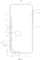
- An extension direction of the second edge 12 is a horizontal direction (an X direction shown in the figure), and an extension direction of the first edge 11 is a vertical direction (a Y direction shown in the figure).
- a length of the first edge 11 is greater than a length of the second edge 12.
- the extension direction of the first edge 11 and the extension direction of the second edge 12 may be changed, and the length of the first edge 11 and the length of the second edge 12 may also be changed. This is not specifically limited herein.
- the extension direction of the first edge 11 may be the horizontal direction
- the extension direction of the second edge 12 may be the vertical direction.
- the length of the first edge 11 may be less than the length of the second edge 12.
- the frame 10 may be made of a conductive material such as metal, or may be made of a non-conductive material such as plastic or resin.
- the display 20 is configured to display an image, a video, and the like.
- the display 20 may be a flexible display or a rigid display.
- the display 20 may be an organic light-emitting diode (organic light-emitting diode, OLED) display, an active-matrix organic light-emitting diode (active-matrix organic light-emitting diode, AMOLED) display, a mini organic light-emitting diode (mini organic light-emitting diode) display, a micro light-emitting diode (micro organic light-emitting diode) display, a micro organic light-emitting diode (micro organic light-emitting diode) display, a quantum dot light-emitting diode (quantum dot light emitting diodes, QLED) display, or a liquid crystal display (Liquid Crystal Display, LCD).
- OLED organic light-emitting diode
- AMOLED active-matrix organic light
- the electronic device 100 further includes an antenna 40 and a radio frequency front end 50.
- the antenna 40 includes an antenna body 41.
- the antenna body 41 is configured to radiate a radio frequency signal to the outside or receive a radio frequency signal from the outside, so that the electronic device 100 can communicate with the outside by using the antenna body 41.
- the radio frequency front end 50 connects to the antenna body 41, and is configured to feed a radio frequency signal into the antenna body 41 or receive an external radio frequency signal received by the antenna body 41.
- the radio frequency front end 50 includes a transmit channel and a receive channel.
- the transmit channel includes components such as a power amplifier and a filter.
- the antenna body 41 is of an L-shaped structure, and includes a first section 411 and a second section 412 that intersects with the first section 411.
- An end that is of the first section 411 and that is far away from the second section 412 is a first end A
- an end that is of the second section 412 and that is far away from the first section 411 is a second end B.
- the first end A and the second end B may be interchanged.
- the end that is of the second section 412 and that is far away from the first section 411 is the first end A
- the end that is of the first section 411 and that is far away from the second section 412 is the second end B.
- the antenna body 41 includes a feed point 413 and a grounding point 414 that are disposed with an interval.
- the grounding point 414 may be located between the feed point 413 and the first end A, or may be located between the feed point 413 and the second end B.
- the feed point 413 is configured to electrically connect to the radio frequency front end 50, so that a signal generated by the radio frequency front end 50 can be transmitted to the antenna body 41 through the feed point 413, and transmitted to the outside through the antenna body 41. Alternatively, the external signal received by the antenna body 41 is transmitted to the radio frequency front end 50 through the feed point 413.
- the feed point 413 in this application is not an actual point, and a position at which the radio frequency front end 50 connects to the antenna body 41 is the feed point 413 in this application.
- the grounding point 414 is grounded, and an electrical length of the antenna body 41 can be adjusted by adjusting a position of the grounding point 414. A resonance frequency of the antenna body 41 can be changed if the electrical length is changed.
- the grounding point 414 is grounded by using a grounding member such as a grounding pin or a grounding wire. One end of the grounding member connects to the grounding point 414 of the antenna body 41, and the other end is grounded, so that the grounding point 414 is grounded. It should be noted that the grounding point 414 in this application is not an actual point, and a position at which the grounding member such as the grounding pin or the grounding wire connects to the antenna body 41 is the grounding point 414.
- the electrical length of the antenna body 41 in this application may be measured in a plurality of manners.
- the electrical length of the antenna body 41 may be measured by using a passive test method. Specifically, the antenna is manufactured into a jig, each of the first end A and the second end B of the antenna body 41 is sealed with a copper sheet, and changes of return loss diagrams of the antenna measured at different moments are observed, to determine an electrical length, of the antenna body 41, between the first end A and the second end B and an electrical length between the feed point 413 and the first end A or the second end B.
- FIG. 3 is a schematic diagram of an internal structure of the electronic device 100 shown in FIG. 1 .
- the electronic device 100 further includes a middle frame 30.
- the display 20 is stacked with the middle frame 30, and the frame 10 is disposed around the middle frame 30.
- the middle frame 30 is made of a conductive material (for example, a metal material) such as metal, and the middle frame 30 is grounded.
- the frame 10 is made of a conductive material, at least a part of the frame 10 may electrically connect to the middle frame 30, to ground the frame 10 by using the middle frame 30.
- the electronic device 100 may not include the middle frame 30, and the frame 10 may connect to another grounding position by using a grounding member, to implement grounding.
- the frame 10 is made of a metal material, and some sections of the frame 10 can be used as the antenna body 41, to reduce space occupied by the antenna 40.
- a first slot 111 is disposed on one first edge 11
- a second slot 121 is disposed on a second edge 12
- the frame 10 between the first slot 111 and the second slot 121 forms the antenna body 41 in this embodiment.
- a part that is of the first edge 11 and that is between the first slot 111 and the second edge 12 is the first section 411 of the antenna body 41
- a part that is of the second edge 12 and that is between the second slot 121 and the first edge 11 is the second section 412 of the antenna body 41.
- the antenna body 41 is electrically isolated from a part other than the antenna body 41 on the frame 10 by using the first slot 111 and the second slot 121. In addition, there is a gap 42 between the antenna body 41 and the middle frame 30, to ensure a good clearance environment for the antenna body 41, so that the antenna 40 has a good signal transmission function.
- the part other than the antenna body 41 on the frame 10 may connect to the middle frame 30, and may be integrally formed with the middle frame 30.
- the part other than the antenna body 41 on the frame 10 is used as an antenna body of another antenna (for example, a Wi-Fi antenna or a GPS antenna) of the electronic device, there is also a gap 42 between the part other than the antenna body on the frame 10 and the middle frame 30, to ensure a good clearance environment for the antenna.
- another antenna for example, a Wi-Fi antenna or a GPS antenna
- the antenna body 41 includes the first end A and the second end B.
- an end face of the first end A faces the first slot 111
- an end face of the second end B faces the second slot 121.
- the first end A is located in the vertical direction of the electronic device 100
- the second end B is located in the horizontal direction of the electronic device 100. It may be understood that when the extension direction of the first edge 11 of the antenna body 41 is the horizontal direction, and the extension direction of the second edge 12 is the vertical direction, the first end A whose end face faces the first slot 111 is located in the horizontal direction, and the second end B whose end face faces the second slot 121 is disposed in the vertical direction.
- a distance between the first slot 111 and the second edge 12 and a distance between the second slot 121 and the first edge 11 are not specifically limited.
- the distance between the first slot 111 and the second edge 12 or the distance between the second slot 121 and the first edge 11 is greater than 90 mm, to avoid, to some extent, a case in which the first slot 111 or the second slot 121 is held when the electronic device is held by a hand. Therefore, the antenna 40 can still have relatively good radiation performance in a handheld state.
- the length of the first edge 11 is greater than the length of the second edge 12, and the distance between the first slot 111 and the second edge 12 is greater than the distance between the second slot 121 and the first edge, that is, a length of the first section 411 is greater than a length of the second section 412.
- the second section 412 that is of a relatively short length and that is of the antenna body 41 is located on the second edge 12 that is of a relatively short length and that is of the frame 10
- the first section 411 that is of a relatively long length and that is of the antenna body 41 is located on the first edge 11 that is of a relatively long length and that is of the frame 10, and therefore more L-shaped antennas can be further arranged on the frame 10, to implement a relatively proper antenna arrangement on the frame 10.
- the first slot 111 and the second slot 121 may be filled with a dielectric material, to further enhance an electrical isolation effect between the antenna body 41 and a part other than the antenna body 41 on the frame 10.
- the frame 10 of the electronic device 100 when the frame 10 of the electronic device 100 is made of a non-conductive material, the frame 10 cannot be used as the antenna body 41.
- a difference between this embodiment and the embodiment shown in FIG. 3 lies in that the antenna body 41 is located in the electronic device 100.
- the antenna body 41 is disposed abut to the frame 10, to minimize a size occupied by the antenna 40 and enable the antenna 40 to be closer to the outside of the electronic device 100, so as to implement a better signal transmission effect.
- the antenna body 41 is disposed abut to the frame 10 means that the antenna body 41 may be disposed in close contact with the frame 10, or may be disposed close to the frame 10, that is, there can be a small gap between the antenna body 41 and the frame 10.
- the first slot 111 and the second slot 121 do not need to be disposed on the frame 10, and a radio frequency signal output or received by the antenna body 41 can be transmitted through the frame 10, to prevent the frame 10 from restricting signal transmission of the antenna 40.
- the antenna body 41 connects to the middle frame 30 by using a grounding pin 44.
- the middle frame 30 is grounded, and therefore the grounding point 414 is grounded by using the grounding pin 44.
- one end of the grounding pin 44 connects to the antenna body 41, and the other end connects to the middle frame 30.
- a position at which the grounding pin 44 connects to the antenna body 41 is the grounding point 414 of the antenna body 41.
- the antenna body 41 connects to the radio frequency front end 50 by using a feed pin 43.
- one end of the feed pin 43 connects to the antenna body 41, and the other end connects to the radio frequency front end 50.
- a position at which the feed pin 43 connects to the antenna body 41 is the feed point 413 of the antenna body 41.
- the antenna body 41 may connect to the middle frame 30 by using another structure such as a connection lead, or may connect to the radio frequency front end 50 by using another structure such as a connection lead. This is not specifically limited herein.
- an electrical length between the feed point 413 and the first end A is greater than an electrical length between the feed point 413 and the second end B, and the electrical length between the feed point 413 and the first end A is approximately quarter of a first wavelength, so that resonance of quarter of the first wavelength can be generated in a section between the feed point 413 and the first end A of the antenna body 41.
- the first wavelength is an operating wavelength of the resonance of quarter of the first wavelength. For example, in the embodiment shown in FIG.
- the electrical length between the feed point 413 and the first end A is greater than the electrical length between the feed point 413 and the second end B, and therefore it is set that a section (namely, the section between the feed point 413 and the first end A) of a relatively long electrical length is of approximately quarter of the first wavelength, to generate the resonance of quarter of the first wavelength, so that the resonance of quarter of the first wavelength can have a relatively large radiation aperture. Therefore, the antenna 40 has relatively good radiation performance.
- the feed point 413 may be disposed at any position of the antenna body 41. Specifically, a position of the feed point 413 or a position of the first end A may be correspondingly changed based on a specific actual situation of the electronic device 100, to control a direction in which mode excitation is to be generated. For example, when the electronic device 100 shown in FIG. 3 is designed with a narrow chin structure, there is relatively small clearance space on a bottom edge (an edge that extends in a direction of an X axis in FIG. 3 ) of the electronic device 100. When there is a relatively good clearance environment on a side edge (an edge that extends in the Y direction in FIG.
- the first edge 11 of the frame 10 may be disposed at a position on the side edge of the electronic device, so that the extension direction of the first edge 11 is the Y direction, and the first end A is located in the vertical direction, to obtain horizontal mode excitation.
- the first edge 11 of the frame 10 may be disposed at a position on the bottom edge of the electronic device, so that the extension direction of the first edge 11 is the X direction, and the first end A is located in the horizontal direction, to obtain vertical mode excitation.
- the extension direction of the first edge 11 is the Y direction, and the first end A is located in the vertical direction.
- the feed point 413 is located in the first section 411 of the antenna body 41.
- the length of the first section 411 of the antenna body 41 is greater than the length of the second section 412, and therefore when the feed point 413 is disposed in the first section 411, a physical length between the feed point 413 and the first end A is usually greater than a physical length between the feed point 413 and the second end B.
- a case in which the electrical length between the feed point 413 and the first end A is greater than the electrical length between the feed point 413 and the second end B and the resonance of quarter of the first wavelength can be generated between the feed point 413 and the first end A can be implemented by connecting only a tuning element with a relatively small specification or without connecting a tuning element between the feed point 413 and the first end A. In this way, manufacturing costs can be reduced.
- the electrical length between the first end A and the second end B is approximately half of a second wavelength
- the antenna body 41 can generate resonance of half of the second wavelength between the first end A and the second end B.
- the second wavelength is a wavelength of the resonance that is of half of the second wavelength and that is formed between the first end A and the second end B.
- the first wavelength and the second wavelength are operating wavelengths of signals whose radiation frequencies fall within a same frequency band (for example, B28, B5, or B8) in an LTE standard.
- the antenna body 41 is L-shaped, and therefore mode excitation in a direction perpendicular to the first section 411 and mode excitation in a direction perpendicular to the second section 412 can be generated, that is, horizontal mode excitation and vertical mode excitation can be generated, which can assist in enhancing the mode excitation generated based on the resonance of quarter of the first wavelength, so that horizontal mode excitation and vertical mode excitation of the antenna 40 can be relatively strong, that is, both the horizontal mode excitation and the vertical mode excitation of the antenna can be relatively balanced. Therefore, the antenna 40 still has relatively good antenna radiation performance in the handheld state.
- the antenna body 41 can generate both the resonance of quarter of the first wavelength and the resonance of half of the second wavelength, and the mode excitation generated based on the resonance of quarter of the first wavelength can be enhanced by using the resonance of half of the second wavelength, so that the horizontal mode excitation and the vertical mode excitation of the antenna 40 are relatively balanced. Therefore, the antenna 40 can have relatively good radiation performance regardless of whether the electronic device 100 is in free space (FS) or in the handheld state.
- FS free space
- horizontal mode excitation is generated based on the resonance of quarter of the first wavelength
- horizontal mode excitation and vertical mode excitation are generated based on the resonance of half of the second wavelength, so that when the electronic device 100 is in the free space, both the horizontal mode excitation and the vertical mode excitation are relatively strong. Therefore, the antenna 40 has relatively good radiation performance.
- holding of the first edge 11 of the electronic device 100 partially affects a magnitude of mode excitation of the electronic device 100 in the horizontal direction, but does not affect intensity of vertical mode excitation. Therefore, the antenna 40 still has good radiation performance.
- the antenna 40 still has good radiation performance.
- the resonance of quarter of the first wavelength and the resonance of half of the second wavelength are generated.
- the first wavelength is greater than the second wavelength, that is, a frequency of the resonance of quarter of the first wavelength is less than a frequency of the resonance of half of the second wavelength, to avoid generating an efficiency pit at a same operating frequency band (for example, a frequency band B28, B5, or B8), so that the antenna 40 can have good radiation performance at the operating frequency band.
- a same operating frequency band for example, a frequency band B28, B5, or B8
- a difference between the frequency of the resonance generated between the feed point and the first end and the frequency of the resonance generated between the first end and the second end ranges from 50 MHz to 200 MHz, to implement better compatibility between the resonance of quarter of the first wavelength and the resonance of half of the second wavelength. Therefore, the antenna can have good radiation performance both in the free space and in the handheld state.
- the difference between the frequency of the resonance of quarter of the first wavelength and the frequency of the resonance of half of the second wavelength may range from 50 MHz to 150 MHz.
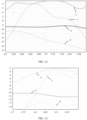
- FIG. 6 is a diagram of curves of a return loss coefficient (S11) of the antenna 40 of the electronic device 100 shown in FIG. 3 in different statuses (including the free space, a beside head and hand left side mode, and a beside head and hand right side mode).
- the first end A is located on the first edge 11 of the frame 10, and the first edge 11 is located in the vertical direction.
- a horizontal coordinate is a frequency (unit: GHz)
- a vertical coordinate is the return loss coefficient (unit: dB).
- a curve a represents a curve diagram of the return loss coefficient of the antenna 40 that exists when the electronic device 100 is in the free space.
- Curves b and c are curve diagrams of the return loss coefficient of the antenna 40 that exists when the electronic device 100 is held by a hand and the electronic device 100 is held in the portrait mode (a handheld state shown in FIG. 5 ).
- the curve b represents a curve diagram of the return loss coefficient of the antenna 40 that exists when the electronic device 100 is in the beside head and hand left side mode (namely, a mode in which the electronic device 100 is held by a left hand and is close to a left side of the face).
- the curve c represents a curve diagram of the return loss coefficient of the antenna 40 that exists when the electronic device 100 is in the beside head and hand right side mode (namely, a mode in which the electronic device 100 is held by a right hand and is close to a right side of the face).
- FIG. 7 is a simulation diagram of a current and radiation direction existing when the antenna 40 of the electronic device 100 shown in FIG. 3 is in the free space.
- FIG. 8 is a diagram of radiation efficiency of the antenna 40 of an example structure of the electronic device 100 shown in FIG. 3 .
- a horizontal coordinate is a frequency (unit: GHz)
- a vertical coordinate is the radiation efficiency (unit: dB).
- a curve a represents a curve diagram of radiation efficiency of the antenna 40 that exists when the electronic device 100 is in the free space.
- a curve b represents a curve diagram of radiation efficiency of the antenna 40 that exists when the electronic device 100 is in the beside head and hand left side mode (namely, a mode in which the electronic device 100 is held by the left hand and is close to the left side of the face).
- a curve c represents a curve diagram of radiation efficiency of the antenna 40 that exists when the electronic device 100 is in the beside head and hand right side mode (namely, a mode in which the electronic device 100 is held by the right hand and is close to the
- the antenna 40 has two antenna modes in the free space, and therefore the antenna 40 has relatively high bandwidth.
- directivity patterns of the two antenna modes are complementary in specific space, so that the antenna 40 can have relatively good radiation efficiency in each direction, and a case in which the antenna 40 encounters a death grip when the electronic device 100 is held by a hand is avoided.
- a directivity pattern obtained after complementation is oblique, and therefore there is no problem of death grip.
- FIG. 6 and FIG. 8 it may be further learned from FIG. 6 and FIG. 8 that in both the beside head and hand left side mode and the beside head and hand right side mode, radiation performance of the antenna 40 is slightly reduced, but the antenna 40 does not encounter a death grip.
- FIG. 9 is another diagram of a curve of a return loss coefficient (S11) of the antenna 40 of an example structure of the electronic device 100 according to this application.
- the first end A of the antenna 40 represented in FIG. 9 is located on the second edge 12 of the frame 10 of the electronic device 100.
- a horizontal coordinate is a frequency (unit: GHz)
- a vertical coordinate is the return loss coefficient (unit: dB).
- a curve a represents a curve diagram of the return loss coefficient of the antenna 40 that exists when the electronic device 100 is in the free space.
- Curves b and c are curve diagrams of the return loss coefficient of the antenna 40 that exists when the electronic device 100 is held by a hand and the electronic device 100 is in the portrait mode.
- the curve b represents a curve diagram of the return loss coefficient of the antenna 40 that exists when the electronic device 100 is in the beside head and hand left side mode (namely, a mode in which the electronic device 100 is held by a left hand and is close to a left side of the face).
- the curve c represents a curve diagram of the return loss coefficient of the antenna 40 that exists when the electronic device 100 is in the beside head and hand right side mode (namely, a mode in which the electronic device 100 is held by a right hand and is close to a right side of the face).
- FIG. 10 is a diagram of system efficiency of the antenna 40 represented in FIG. 9 .
- a horizontal coordinate is a frequency (unit: GHz)
- a vertical coordinate is radiation efficiency (unit: dB).
- the antenna 40 when the first end A is located on the second edge 12 of the frame 10, the antenna 40 has two antenna modes in the free space, and therefore the antenna 40 has relatively high bandwidth.
- the antenna 40 in both the beside head and hand left side mode and the beside head and hand right side mode, radiation performance of the antenna 40 is slightly reduced, but the antenna 40 does not encounter a death grip.
- the antenna 40 there is a reduction in the radiation efficiency of the antenna 40 when the radiation efficiency in the beside head and hand mode (including the beside head and hand left side mode or the beside head and hand right side mode) is compared with that in the free space, but the antenna 40 still has relatively good radiation efficiency.
- FIG. 12 is a diagram of system efficiency and radiation efficiency existing when the antenna 40 of an example structure of the electronic device 100 shown in FIG. 3 is in the free space and the handheld state.
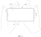
- the electronic device When the electronic device is held by a hand, the electronic device is in a landscape mode shown in FIG. 11 . In this case, the second edge 12 of the electronic device 100 is held by a hand.
- a horizontal coordinate is a frequency (unit: GHz)
- a vertical coordinate is efficiency (unit: dB).
- a curve a represents a curve diagram of radiation efficiency of the antenna 40 that exists when the electronic device 100 is in the free space.
- a curve b represents a curve diagram of radiation efficiency of the antenna 40 that exists when the electronic device 100 is in the landscape mode and the second edge 12 of the electronic device 100 is held by a hand.
- a curve c represents a curve diagram of system efficiency of the antenna 40 that exists when the electronic device 100 is in the free space.
- a curve d represents a curve diagram of system efficiency of the antenna 40 that exists when the electronic device 100 is in the landscape mode and the second edge 12 of the electronic device 100 is held by a hand. It may be learned from the curves c and d that when the electronic device 100 is in the landscape mode, the antenna 40 does not encounter a death grip when the two opposite second edges 12 of the electronic device 100 are held by a hand.
- FIG. 13 is a diagram of system efficiency and radiation efficiency of the antenna 40 of the electronic device 100 shown in FIG. 3 in different statuses.
- a horizontal coordinate is a frequency (unit: GHz), and a vertical coordinate is efficiency (unit: dB).
- a curve a represents a curve diagram of radiation efficiency of the antenna 40 that exists when the electronic device 100 is in the free space.
- a curve b represents a curve diagram of radiation efficiency of the antenna 40 that exists when the electronic device 100 is held by a hand and the first slot 111 and the second slot 121 of the frame 10 are blocked.
- a curve c represents a curve diagram of system efficiency of the antenna 40 that exists when the electronic device 100 is in the free space.
- a curve d represents a curve diagram of system efficiency of the antenna 40 that exists when the electronic device 100 is held by a hand and the first slot 111 and the second slot 121 of the frame 10 are blocked. It may be learned from the curves c and d that when the electronic device 100 is held by a hand and the first slot 111 and the second slot 121 of the frame 10 are blocked, the antenna 40 does not encounter a death grip.
- the third tuning element 45 is connected between the grounding point 414 and the grounding position, to change the electrical length, of the antenna body 41, between the first end A and the second end B and the electrical length, of the antenna body 41, between the feed point 413 and the first end A or the second end B, so as to adjust an operating frequency of an antenna mode generated based on resonance of the antenna body 41.
- the grounding position is a position at which the grounding pin 44 connects to one end of the middle frame 30.
- the antenna 40 further includes at least one switching circuit.
- the antenna 40 switches to different operating frequency bands by using the switching circuit, so that the antenna 40 can implement communication at a plurality of different operating frequency bands.
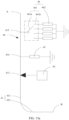
- FIG. 15a is a schematic diagram of a structure of the antenna 40 according to some other embodiments of this application. A difference between the antenna 40 in the embodiment shown in FIG. 15a and that in the embodiment shown in FIG. 3 lies in that the antenna 40 further includes a first switching circuit 46.
- a first connection point 415 is disposed on the antenna body 41, and the first connection point 415 is located on a side that is of the feed point 413 and the grounding point 414 and that is far away from the first end A or on a side that is of the feed point 413 and the grounding point 414 and that is far away from the second end B. It should be noted that in this application, the first connection point 415 is not an actual point, and a position at which the first switching circuit 46 connects to the antenna body 41 is the first connection point 415.
- the first switching circuit 46 includes a first switch 461 and at least one grounded first tuning element 462.
- the first tuning element 462 may be a capacitive element or an inductive element, or may be obtained with capacitive or inductive elements connected in parallel or connected in series. At least one means one or more.
- the capacitive or inductive elements connected in parallel or in series mean that the first tuning element 462 may be obtained with a plurality of capacitive elements disposed in parallel or disposed in series, may be obtained with a plurality of inductive elements connected in parallel or connected in series, or may be obtained with a capacitive element and an inductive element connected in parallel or connected in series.
- One end of the first switch 461 connects to the first connection point 415, and the other end may connect to different first tuning elements 462 through switching, to connect different first tuning elements 462 (which may be first tuning elements 462 of different types, or may be first tuning elements 462 that are of a same type and that differ in specification and size) to the antenna body 41.
- the first connection point 415 is located on the side that is of the feed point 413 and the grounding point 414 and that is far away from the second end B, to change the electrical length between the feed point 413 and the first end A and the electrical length (the electrical length between the first end A and the second end B) of the antenna body 41, so as to change the frequency of the resonance of quarter of the first wavelength and the frequency of the resonance of half of the second wavelength, so that the antenna 40 can cover different operating frequency bands.
- the first switch 461 may be various types of switches.
- the first switch 461 may be a physical switch such as a single-pole single-throw switch, a single-pole multi-throw switch, or a multi-pole multi-throw switch, or may be a switchable interface such as a mobile industry processor interface (Mobile Industry Processor Interface, MIPI) or a general-purpose input/output (General-purpose input/output, GPIO) interface.
- the first switch 461 includes a first movable end 461a and a plurality of first fixed ends 461b.
- different first tuning elements 462 connect to the antenna body 41, to adjust the electrical length of the antenna body 41, so as to change the frequency of the resonance of quarter of the first wavelength and the frequency of the resonance of half of the second wavelength.
- the first switch 461 may include one or more first movable ends 461a.
- the first switch 461 is a single-pole multi-throw switch, that is, the first switch 461 includes a plurality of first fixed ends 461b.
- Each first fixed end 461b connects to one first tuning element 462, and different first fixed ends 461b connect to different first tuning elements 462 (which may differ in type or specification and size).
- the electrical length between the feed point 413 and the first end A is changed, and therefore the frequency of the resonance that is of quarter of the first wavelength and that is generated between the feed point 413 and the first end A is changed.
- the electrical length between the first end A and the second end B is changed, and therefore the frequency of the resonance that is of half of the second wavelength and that is of the antenna 40 is changed.
- FIG. 15b is another schematic diagram of a structure of the antenna 40 according to this application.
- the first switch 461 is a multi-pole multi-throw switch, and a quantity of first movable ends 461a is the same as a quantity of first fixed ends 461b.
- One end of each of the four first movable ends 461a connects to the first connection point 415, and the other end connects to or is disconnected from a first fixed end 461b corresponding to the first movable end 461a.
- first tuning elements 462 that connect to the antenna body 41 can be controlled, to change the electrical length between the feed point 413 and the first end A of the antenna body 41 and the overall electrical length between the first end A and the second end B, so as to change the frequency of the resonance of quarter of the first wavelength and the frequency of the resonance of half of the second wavelength.
- first tuning elements 462 connect to the antenna body 41, and the two first tuning elements 462 are disposed in parallel.
- FIG. 16 is a schematic diagram of a structure of the antenna 40 according to some other embodiments of this application.
- the antenna 40 further includes a second switching circuit 47.
- a second connection point 416 is disposed on the antenna body 41, and the second switching circuit 47 connects to the second connection point 416.
- the second connection point 416 is not an actual point, and a position at which the second switching circuit 47 connects to the antenna body 41 is the second connection point 416.
- the feed point 413 and the grounding point 414 are located between the first connection point 415 and the second connection point 416.
- the second switching circuit 47 is of a structure similar to that of the first switching circuit 46, and includes a second switch 471 and a plurality of second tuning elements 472.
- the second switch 471 may connect to different second tuning elements 472 through switching.
- the first switching circuit 46 cooperates with the second switching circuit 47, to change the operating frequency of the resonance of quarter of the first wavelength and the operating frequency of the resonance of half of the second wavelength.
- switching is performed for the first switch 461 of the first switching circuit 46, so that different first tuning elements 462 connect to the antenna body 41, and the second switch 471 of the second switching circuit 47 connects to different second tuning elements 472 through switching, to change the electrical length between the feed point 413 and the first end A or the second end B and the electrical length between the first end A and the second end B, so as to change the operating frequency of the resonance of quarter of the first wavelength and the operating frequency of the resonance of half of the second wavelength.
- the antenna 40 can cover more operating frequency bands.
- the second switch 471 may also be a physical switch such as a single-pole single-throw switch, a single-pole multi-throw switch, or a multi-pole multi-throw switch, or may be a switchable interface such as a mobile industry processor interface (Mobile Industry Processor Interface, MIPI) or a general-purpose input/output (General-purpose input/output, GPIO) interface.
- the second switch 471 is a single-pole multi-throw switch, and includes a second movable end 471a and a plurality of second fixed ends 471b. One end of each second tuning element 472 correspondingly connects to one second fixed end 471b, and the other end is grounded. One end of the second movable end 471a connects to the second connection point 416, and the other end may connect to different second tuning elements 472 through switching.
- second tuning elements 472 that connect to the second fixed ends 471b of the second switching circuit 47 are in a one-to-one correspondence with first tuning elements 462 that connect to the first fixed ends 461b of the first switching circuit 46.
- the second switch 471 connects, through switching, to a second tuning element 472 corresponding to the first tuning element 462 that connects to the first switch 461, to correspondingly adjust the electrical length of each section of the antenna 40, so that the electrical length between the feed point 413 and the first end A can always be greater than the electrical length between the feed point 413 and the second end B, and it is ensured that the operating frequency of the resonance of quarter of the first wavelength is less than the frequency of the resonance of half of the second wavelength, and the difference between the frequency of the resonance of quarter of the first wavelength and the frequency of the resonance of half of the second wavelength ranges from 50 MHz to 200 MHz.
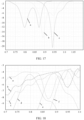
- FIG. 17 and FIG. 18 are respectively a diagram of a return loss and a diagram of system efficiency and radiation efficiency that exist when the first movable end 461a of the first switch 461 of the antenna 40 shown in FIG. 16 separately connects to three different first tuning elements 462 through switching and the second switch 471 switch correspondingly connects, through switching, to second tuning elements 472 corresponding to the first tuning elements 462 that connect to the first switch 461.
- a horizontal coordinate is a frequency (unit: GHz)
- a vertical coordinate is a return loss coefficient (unit: dB).
- a horizontal coordinate is a frequency (unit: GHz)
- a vertical coordinate is efficiency (unit: dB).
- curves a, b, and c respectively represent curve diagrams of radiation efficiency that are generated by the antenna 40 at the antenna frequency bands B28 (from 703 MHz to 803 MHz), B5 (from 824 MHz to 894 MHz), and B8 (from 880 MHz to 960 MHz) when the electronic device 100 is in the free space
- curves d, e, and f respectively represent curve diagrams of system efficiency that are generated by the antenna 40 at the antenna frequency bands B28, B5, and B8. It may be learned from FIG. 18 that at bandwidth of 80 MHz of each of different operating frequency bands (including B28, B5, and B8), efficiency of the antenna 40 is less than -6 dB, and therefore the antenna 40 has good radiation performance.
- the first switch 461 of the first switching circuit 46 and the second switching circuit 47 is a single-pole four-throw switch, so that the antenna 40 can cover four different operating frequencies. It may be understood that based on an actual requirement, the antenna 40 can cover more operating frequency bands by increasing a quantity of switching circuits, by using different first switches 461 and second switches 471, or the like.
- the first switch 461 of the first switching circuit 46 and the second switching circuit 47 is a multi-pole four-throw switch, so that the antenna 40 can cover 24 operating frequencies.
Landscapes
- Engineering & Computer Science (AREA)
- Computer Networks & Wireless Communication (AREA)
- Support Of Aerials (AREA)
- Waveguide Aerials (AREA)
- Details Of Aerials (AREA)
Claims (15)
- Antenne (40), umfassend einen L-förmigen Antennenkörper (41), wobei der Antennenkörper (41) einen ersten Abschnitt (411) und einen zweiten Abschnitt (412), der sich mit dem ersten Abschnitt (411) schneidet, umfasst, der Antennenkörper (41) einen Speisepunkt (413) und einen Erdungspunkt (414), die mit einem Abstand angeordnet sind, umfasst, der Speisepunkt (413) dazu konfiguriert ist, sich mit einem Hochfrequenz-Frontend (50) zu verbinden, und die Antenne (40) ferner ein Abstimmelement (45), das zwischen dem Erdungspunkt (414) und einer Erdungsposition des Erdungspunkts (414) verbunden ist, umfasst, und das Abstimmelement (45) dazu konfiguriert ist, eine elektrische Länge des Antennenkörpers (41) einzustellen;der Antennenkörper (41) ein erstes Ende (A) und ein zweites Ende (B), die voneinander entfernt sind, umfasst, das erste Ende (A) ein Ende ist, das zu dem ersten Abschnitt (411) gehört und das weit von dem zweiten Abschnitt (412) entfernt ist, das zweite Ende (B) ein Ende ist, das zu dem zweiten Abschnitt (412) gehört und das weit von dem ersten Abschnitt (411) entfernt ist, eine elektrische Länge zwischen dem Speisepunkt (413) und dem ersten Ende (A) größer als eine elektrische Länge zwischen dem Speisepunkt (413) und dem zweiten Ende (B) ist, und wobeider Antennenkörper (41) dazu konfiguriert ist, eine Resonanz von einem Viertel einer ersten Wellenlänge zwischen dem Speisepunkt (413) und dem ersten Ende (A) zu erzeugen, der Antennenkörper (41) dazu konfiguriert ist, eine Resonanz von einer Hälfte einer zweiten Wellenlänge zwischen dem ersten Ende (A) und dem zweiten Ende (B) zu erzeugen, und die erste Wellenlänge größer als die zweite Wellenlänge ist;wobei eine Differenz zwischen einer Resonanzfrequenz der ersten Wellenlänge und einer Resonanzfrequenz der zweiten Wellenlänge im Bereich von 50 MHz bis 200 MHz liegt.
- Antenne nach Anspruch 1, wobei die Antenne einen ersten Schaltkreis umfasst, ein erster Verbindungspunkt an dem Antennenkörper angeordnet ist, sich der erste Verbindungspunkt auf einer Seite, die zu dem Speisepunkt und dem Erdungspunkt gehört und weit von dem zweiten Ende entfernt ist, befindet, sich ein Ende des ersten Schaltkreises mit dem ersten Verbindungspunkt verbindet und das andere Ende geerdet ist und der erste Schaltkreis dazu konfiguriert ist, die elektrische Länge zwischen dem Speisepunkt und dem ersten Ende zu ändern.
- Antenne nach Anspruch 2, wobei die Antenne einen zweiten Schaltkreis umfasst, ein zweiter Verbindungspunkt ferner an dem Antennenkörper angeordnet ist, sich der Speisepunkt und der Erdungspunkt zwischen dem ersten Verbindungspunkt und dem zweiten Verbindungspunkt befinden, sich ein Ende des zweiten Schaltkreises mit dem zweiten Verbindungspunkt verbindet und das andere Ende geerdet ist und der zweite Schaltkreis dazu konfiguriert ist, die elektrische Länge zwischen dem Speisepunkt und dem zweiten Ende zu ändern.
- Antenne nach Anspruch 2 oder 3, wobei der erste Schaltkreis einen ersten Schalter und eine Vielzahl von verschiedenen ersten Abstimmelementen, die geerdet sind, umfasst und sich der erste Schalter durch Schalten mit den verschiedenen ersten Abstimmelementen verbindet, um die elektrische Länge zwischen dem Speisepunkt und dem ersten Ende zu ändern.
- Antenne nach Anspruch 3, wobei der erste Schaltkreis einen ersten Schalter und eine Vielzahl von verschiedenen ersten Abstimmelementen, die geerdet sind, umfasst, der zweite Schaltkreis einen zweiten Schalter und eine Vielzahl von verschiedenen zweiten Abstimmelementen, die geerdet sind, umfasst, die Vielzahl von ersten Abstimmelementen in einer Einszu-eins-Entsprechung mit der Vielzahl von zweiten Abstimmelementen steht, und, wenn sich der erste Schalter durch Schalten mit den verschiedenen ersten Abstimmelementen verbindet, sich der zweite Schalter durch Schalten mit einem zweiten Abstimmelement, das einem ersten Abstimmelement entspricht, das sich mit dem ersten Schalter verbindet, verbindet.
- Antenne nach Anspruch 5, wobei der erste Schalter eine Vielzahl von ersten festen Enden und ein erstes bewegliches Ende, das sich durch Schalten mit der Vielzahl von ersten festen Enden verbindet, umfasst, sich das erste bewegliche Ende mit dem ersten Verbindungspunkt verbindet und sich jedes erste feste Ende mit einem ersten Abstimmelement verbindet; und
der zweite Schalter eine Vielzahl von zweiten festen Enden und ein zweites bewegliches Ende, das sich durch Schalten mit der Vielzahl von zweiten festen Enden verbindet, umfasst, sich das zweite bewegliche Ende mit dem zweiten Verbindungspunkt verbindet und sich jedes zweite feste Ende mit einem zweiten Abstimmelement verbindet. - Antenne nach Anspruch 5 oder 6, wobei jedes der Vielzahl von ersten Abstimmelementen oder jedes der Vielzahl von zweiten Abstimmelementen eines oder mehrere von Folgendem umfasst: einen Kondensator, eine Induktivität und einen Widerstand, die parallel geschaltet oder in Reihe geschaltet sind.
- Antenne nach einem der Ansprüche 1 bis 7, wobei das Abstimmelement (45) einen Kondensator oder eine Induktivität umfasst oder einen Kondensator und eine Induktivität umfasst, die parallel angeordnet oder in Reihe angeordnet sind.
- Antenne nach einem der Ansprüche 1 bis 8, wobei die Differenz zwischen der Resonanzfrequenz der ersten Wellenlänge und der Resonanzfrequenz der zweiten Wellenlänge im Bereich von 50 MHz bis 150 MHz liegt.
- Antenne nach einem der Ansprüche 1 bis 9, wobei eine physikalische Länge zwischen dem Speisepunkt (413) und dem ersten Ende (A) größer als eine physikalische Länge zwischen dem Speisepunkt (413) und dem zweiten Ende (B) ist.
- Antenne nach einem der Ansprüche 1 bis 10, wobei die Modusanregung, die basierend auf der Resonanz von einem Viertel der ersten Wellenlänge erzeugt wurde, durch die Resonanz von einer Hälfte der zweiten Wellenlänge verstärkt wird.
- Elektronische Vorrichtung, umfassend einen leitfähigen Rahmen, ein Hochfrequenz-Frontend und die Antenne nach einem der Ansprüche 1 bis 11, wobei der Rahmen eine erste Kante und eine zweite Kante, welche die erste Kante schneidet, umfasst, ein erster Schlitz an der ersten Kante angeordnet ist, ein zweiter Schlitz an der zweiten Kante angeordnet ist, ein Teil, der zu dem Rahmen gehört und sich zwischen dem ersten Schlitz und dem zweiten Schlitz befindet, den L-förmigen Antennenkörper der Antenne bildet, ein Abschnitt, der zu dem Rahmen gehört und sich zwischen dem ersten Schlitz und der zweiten Kante befindet, ein erster Abschnitt des Antennenkörpers ist, und ein Abschnitt, der zu dem Rahmen gehört und sich zwischen dem zweiten Schlitz und der ersten Kante befindet, ein zweiter Abschnitt des Antennenkörpers ist; und
sich das Hochfrequenz-Frontend mit dem Speisepunkt des Antennenkörpers verbindet und dazu konfiguriert ist, ein Hochfrequenzsignal in den Antennenkörper einzuspeisen oder ein Hochfrequenzsignal, das von dem Antennenkörper übertragen wurde, zu empfangen. - Elektronische Vorrichtung nach Anspruch 12, wobei eine Länge einer ersten Kante größer als eine Länge einer zweiten Kante ist und ein Abstand zwischen einem ersten Schlitz und der zweiten Kante größer als ein Abstand zwischen einem zweiten Schlitz und der ersten Kante ist.
- Elektronische Vorrichtung nach Anspruch 12 oder 13, wobei der Abstand zwischen dem ersten Schlitz und der zweiten Kante größer als oder gleich 90 mm ist.
- Elektronische Vorrichtung nach einem der Ansprüche 12 bis 14, wobei sich der Speisepunkt an der ersten Kante befindet.
Priority Applications (1)
| Application Number | Priority Date | Filing Date | Title |
|---|---|---|---|
| EP24209531.3A EP4528927A3 (de) | 2019-08-23 | 2020-08-07 | Antenne und elektronische vorrichtung |
Applications Claiming Priority (2)
| Application Number | Priority Date | Filing Date | Title |
|---|---|---|---|
| CN201910794483.XA CN112421211B (zh) | 2019-08-23 | 2019-08-23 | 天线及电子设备 |
| PCT/CN2020/107867 WO2021036753A1 (zh) | 2019-08-23 | 2020-08-07 | 天线及电子设备 |
Related Child Applications (1)
| Application Number | Title | Priority Date | Filing Date |
|---|---|---|---|
| EP24209531.3A Division EP4528927A3 (de) | 2019-08-23 | 2020-08-07 | Antenne und elektronische vorrichtung |
Publications (3)
| Publication Number | Publication Date |
|---|---|
| EP4016727A1 EP4016727A1 (de) | 2022-06-22 |
| EP4016727A4 EP4016727A4 (de) | 2022-10-05 |
| EP4016727B1 true EP4016727B1 (de) | 2024-11-27 |
Family
ID=74685021
Family Applications (2)
| Application Number | Title | Priority Date | Filing Date |
|---|---|---|---|
| EP20856523.4A Active EP4016727B1 (de) | 2019-08-23 | 2020-08-07 | Antenne und elektronische vorrichtung |
| EP24209531.3A Pending EP4528927A3 (de) | 2019-08-23 | 2020-08-07 | Antenne und elektronische vorrichtung |
Family Applications After (1)
| Application Number | Title | Priority Date | Filing Date |
|---|---|---|---|
| EP24209531.3A Pending EP4528927A3 (de) | 2019-08-23 | 2020-08-07 | Antenne und elektronische vorrichtung |
Country Status (8)
| Country | Link |
|---|---|
| US (1) | US12212052B2 (de) |
| EP (2) | EP4016727B1 (de) |
| JP (1) | JP7336589B2 (de) |
| KR (1) | KR102659469B1 (de) |
| CN (4) | CN112421211B (de) |
| BR (1) | BR112022003337B1 (de) |
| ES (1) | ES2998862T3 (de) |
| WO (1) | WO2021036753A1 (de) |
Families Citing this family (15)
| Publication number | Priority date | Publication date | Assignee | Title |
|---|---|---|---|---|
| CN116995414A (zh) | 2020-05-27 | 2023-11-03 | 华为技术有限公司 | 电子设备 |
| CN115117602B (zh) * | 2021-03-23 | 2023-08-29 | 北京小米移动软件有限公司 | 一种天线模组和终端设备 |
| CN113314828B (zh) * | 2021-05-27 | 2023-09-01 | 维沃移动通信有限公司 | 电子设备 |
| CN113422619B (zh) * | 2021-06-18 | 2022-05-27 | 安徽安努奇科技有限公司 | 一种调谐电路及通讯设备 |
| CN115810898A (zh) * | 2021-09-14 | 2023-03-17 | 北京小米移动软件有限公司 | 天线结构和电子设备 |
| CN114122693B (zh) * | 2021-11-24 | 2024-01-02 | Oppo广东移动通信有限公司 | 天线装置和电子设备 |
| CN114464984B (zh) * | 2022-03-04 | 2025-01-10 | Oppo广东移动通信有限公司 | 一种天线装置及电子设备 |
| CN116780162A (zh) * | 2022-03-10 | 2023-09-19 | Oppo广东移动通信有限公司 | 天线组件、双频宽带天线和电子设备 |
| CN116130947A (zh) * | 2022-09-09 | 2023-05-16 | 华为技术有限公司 | 天线装置和电子设备 |
| CN118232015A (zh) * | 2022-12-19 | 2024-06-21 | 华为技术有限公司 | 天线和具有所述天线的电子设备 |
| CN118867666A (zh) * | 2023-04-28 | 2024-10-29 | 华为技术有限公司 | 一种电子设备 |
| CN119447822A (zh) * | 2023-07-31 | 2025-02-14 | Oppo广东移动通信有限公司 | 电子设备 |
| CN119542718B (zh) * | 2023-08-29 | 2025-11-11 | Oppo广东移动通信有限公司 | 电子设备 |
| CN120601123A (zh) * | 2024-03-04 | 2025-09-05 | 华为技术有限公司 | 一种天线结构及移动终端 |
| CN119155142B (zh) * | 2024-09-20 | 2025-09-12 | 香港中文大学(深圳) | 六维可移动天线基站的信道估计方法及相关设备 |
Family Cites Families (53)
| Publication number | Priority date | Publication date | Assignee | Title |
|---|---|---|---|---|
| US6362787B1 (en) * | 1999-04-26 | 2002-03-26 | Andrew Corporation | Lightning protection for an active antenna using patch/microstrip elements |
| DE10050902A1 (de) | 2000-10-13 | 2002-04-25 | Alcatel Sa | Antennenanordnung für Mobiltelefone |
| TWI237419B (en) * | 2003-11-13 | 2005-08-01 | Hitachi Ltd | Antenna, method for manufacturing the same and portable radio terminal employing it |
| US7193565B2 (en) * | 2004-06-05 | 2007-03-20 | Skycross, Inc. | Meanderline coupled quadband antenna for wireless handsets |
| JP4707495B2 (ja) * | 2005-08-09 | 2011-06-22 | 株式会社東芝 | アンテナ装置および無線装置 |
| KR100830568B1 (ko) | 2005-08-18 | 2008-05-21 | 노키아 코포레이션 | 셀룰러 통신 단말기용 안테나 장치 |
| US7688273B2 (en) * | 2007-04-20 | 2010-03-30 | Skycross, Inc. | Multimode antenna structure |
| KR101727303B1 (ko) * | 2009-05-26 | 2017-04-14 | 스카이크로스 인코포레이티드 | 통신 장치에서 근거리 방사 및 전자파 흡수율값을 감소시키는 방법 |
| US8477069B2 (en) * | 2009-08-21 | 2013-07-02 | Mediatek Inc,. | Portable electronic device and antenna thereof |
| CN102013568A (zh) * | 2010-12-01 | 2011-04-13 | 惠州Tcl移动通信有限公司 | 一种四频段的内置天线及其移动通信终端 |
| CN102576932A (zh) * | 2011-10-28 | 2012-07-11 | 华为终端有限公司 | 一种天线和终端 |
| CN102544774B (zh) * | 2012-02-23 | 2014-05-07 | 上海安费诺永亿通讯电子有限公司 | 一种多模谐振天线系统 |
| TWI539676B (zh) | 2013-09-03 | 2016-06-21 | 宏碁股份有限公司 | 通訊裝置 |
| US9786994B1 (en) * | 2014-03-20 | 2017-10-10 | Amazon Technologies, Inc. | Co-located, multi-element antenna structure |
| EP3035442B1 (de) * | 2014-03-28 | 2018-09-19 | Huawei Device (Dongguan) Co., Ltd. | Antenne und mobiles endgerät |
| US10270170B2 (en) * | 2014-04-15 | 2019-04-23 | QuantalRF AG | Compound loop antenna system with isolation frequency agility |
| JP2016220169A (ja) | 2015-05-26 | 2016-12-22 | 京セラ株式会社 | チューナブルアンテナ |
| KR102306080B1 (ko) * | 2015-08-13 | 2021-09-30 | 삼성전자주식회사 | 안테나 장치 및 안테나 장치를 포함하는 전자 장치 |
| EP3386030B1 (de) | 2015-12-31 | 2022-08-10 | Huawei Technologies Co., Ltd. | Antennenvorrichtung und endgerät |
| CN107204511B (zh) * | 2016-03-16 | 2019-02-12 | 北京小米移动软件有限公司 | 一种分集天线 |
| CN107275753B (zh) * | 2016-04-08 | 2020-06-19 | 北京小米移动软件有限公司 | 终端的天线 |
| JP6623956B2 (ja) | 2016-07-06 | 2019-12-25 | 株式会社Soken | アンテナ装置 |
| US10389010B2 (en) * | 2016-07-21 | 2019-08-20 | Chiun Mai Communication Systems, Inc. | Antenna structure and wireless communication device using same |
| CN108140948B (zh) | 2016-08-12 | 2020-05-08 | 华为技术有限公司 | 一种通信设备 |
| US10511083B2 (en) | 2016-09-22 | 2019-12-17 | Apple Inc. | Antennas having symmetrical switching architecture |
| KR102586064B1 (ko) | 2017-02-16 | 2023-10-05 | 엘에스엠트론 주식회사 | 안테나 장치 |
| CN106876897A (zh) * | 2017-02-28 | 2017-06-20 | 北京小米移动软件有限公司 | 移动终端及其金属后壳 |
| CN107437661B (zh) * | 2017-04-21 | 2021-07-09 | 瑞声科技(新加坡)有限公司 | 天线及移动终端 |
| JP6953807B2 (ja) | 2017-06-06 | 2021-10-27 | 株式会社Soken | アンテナ装置 |
| CN107181045B (zh) * | 2017-06-19 | 2024-02-20 | 上海传英信息技术有限公司 | 一种移动终端的天线及具有该天线的移动终端 |
| EP3451636B1 (de) * | 2017-08-30 | 2025-09-17 | LG Electronics Inc. | Mobiles endgerät |
| US10700416B2 (en) * | 2017-08-30 | 2020-06-30 | Lg Electronics Inc. | Mobile terminal |
| US10804617B2 (en) * | 2017-09-11 | 2020-10-13 | Apple Inc. | Electronic devices having shared antenna structures and split return paths |
| WO2019090690A1 (zh) | 2017-11-10 | 2019-05-16 | 华为技术有限公司 | 一种移动终端的天线及移动终端 |
| CN108183332A (zh) * | 2017-12-25 | 2018-06-19 | 重庆宝力优特科技有限公司 | 一种金属边框手机天线、控制系统及通讯终端 |
| CN107959103A (zh) * | 2017-12-28 | 2018-04-24 | 上海传英信息技术有限公司 | 一种移动终端的天线及具有该天线的移动终端 |
| CN108336483B (zh) * | 2018-02-02 | 2021-03-02 | Oppo广东移动通信有限公司 | 天线组件、电子设备及天线切换方法 |
| US10833410B2 (en) * | 2018-02-22 | 2020-11-10 | Apple Inc. | Electronic device antennas having multiple signal feed terminals |
| CN108631040A (zh) | 2018-03-28 | 2018-10-09 | 广东欧珀移动通信有限公司 | 电子装置 |
| CN208284641U (zh) | 2018-05-07 | 2018-12-25 | 华勤通讯技术有限公司 | 一种终端设备 |
| CN108808221B (zh) * | 2018-06-19 | 2021-05-04 | 深圳市万普拉斯科技有限公司 | 天线系统及移动终端 |
| CN208622935U (zh) * | 2018-06-20 | 2019-03-19 | 深圳鼎智通讯股份有限公司 | 一种环形缝隙可重构的全金属天线 |
| CN108879116B (zh) * | 2018-06-25 | 2021-06-18 | 维沃移动通信有限公司 | 一种天线系统及终端 |
| CN109149086B (zh) * | 2018-08-03 | 2020-07-07 | 瑞声科技(南京)有限公司 | 天线系统及移动终端 |
| CN109149072B (zh) * | 2018-08-20 | 2020-11-17 | 瑞声科技(新加坡)有限公司 | 天线模组及移动终端 |
| US11258163B2 (en) | 2018-08-30 | 2022-02-22 | Apple Inc. | Housing and antenna architecture for mobile device |
| CN109462016A (zh) * | 2018-09-29 | 2019-03-12 | Oppo广东移动通信有限公司 | 天线装置及电子设备 |
| CN209169370U (zh) | 2018-11-30 | 2019-07-26 | 维沃移动通信有限公司 | 一种终端设备 |
| CN109687151B (zh) * | 2018-12-26 | 2021-12-14 | 维沃移动通信有限公司 | 一种天线结构及移动终端 |
| CN109687111B (zh) * | 2018-12-29 | 2021-03-12 | 维沃移动通信有限公司 | 一种天线结构及通信终端 |
| CN111628298B (zh) | 2019-02-27 | 2022-03-11 | 华为技术有限公司 | 共体天线及电子设备 |
| US10886617B2 (en) | 2019-02-28 | 2021-01-05 | Apple Inc. | Electronic devices with probe-fed dielectric resonator antennas |
| CN110649371B (zh) | 2019-09-27 | 2021-03-16 | 西南交通大学 | 天线及其移动终端设备 |
-
2019
- 2019-08-23 CN CN201910794483.XA patent/CN112421211B/zh active Active
- 2019-08-23 CN CN202210051461.6A patent/CN114447583B/zh active Active
-
2020
- 2020-08-07 EP EP20856523.4A patent/EP4016727B1/de active Active
- 2020-08-07 ES ES20856523T patent/ES2998862T3/es active Active
- 2020-08-07 WO PCT/CN2020/107867 patent/WO2021036753A1/zh not_active Ceased
- 2020-08-07 CN CN202080058796.XA patent/CN114258612B/zh active Active
- 2020-08-07 CN CN202510126311.0A patent/CN119764803A/zh active Pending
- 2020-08-07 JP JP2022512425A patent/JP7336589B2/ja active Active
- 2020-08-07 US US17/637,370 patent/US12212052B2/en active Active
- 2020-08-07 BR BR112022003337-0A patent/BR112022003337B1/pt active IP Right Grant
- 2020-08-07 KR KR1020227007982A patent/KR102659469B1/ko active Active
- 2020-08-07 EP EP24209531.3A patent/EP4528927A3/de active Pending
Also Published As
| Publication number | Publication date |
|---|---|
| CN114447583B (zh) | 2023-09-01 |
| JP2022545894A (ja) | 2022-11-01 |
| BR112022003337A2 (pt) | 2022-05-24 |
| CN114258612B (zh) | 2025-02-21 |
| KR102659469B1 (ko) | 2024-04-19 |
| EP4528927A3 (de) | 2025-04-30 |
| CN112421211B (zh) | 2022-01-14 |
| CN119764803A (zh) | 2025-04-04 |
| ES2998862T3 (en) | 2025-02-21 |
| EP4016727A1 (de) | 2022-06-22 |
| WO2021036753A1 (zh) | 2021-03-04 |
| CN114447583A (zh) | 2022-05-06 |
| CN112421211A (zh) | 2021-02-26 |
| CN114258612A (zh) | 2022-03-29 |
| BR112022003337B1 (pt) | 2024-02-27 |
| JP7336589B2 (ja) | 2023-08-31 |
| KR20220041929A (ko) | 2022-04-01 |
| US20220278446A1 (en) | 2022-09-01 |
| EP4016727A4 (de) | 2022-10-05 |
| US12212052B2 (en) | 2025-01-28 |
| EP4528927A2 (de) | 2025-03-26 |
Similar Documents
| Publication | Publication Date | Title |
|---|---|---|
| US12212052B2 (en) | Antenna and electronic device | |
| US10910698B2 (en) | Mobile device and antenna structure | |
| US10542130B1 (en) | Mobile device | |
| US11145958B2 (en) | Mobile device and manufacturing method thereof | |
| US12294158B2 (en) | Electronic device | |
| TWI784634B (zh) | 天線結構 | |
| US10236558B2 (en) | LTE full-band cellphone antenna structure | |
| US7317901B2 (en) | Slotted multiple band antenna | |
| EP2763240A1 (de) | Antennenanordnung | |
| US20260024913A1 (en) | Antenna Apparatus and Electronic Device | |
| US9306274B2 (en) | Antenna device and antenna mounting method | |
| US11063349B2 (en) | Mobile device | |
| JP6825429B2 (ja) | マルチバンドアンテナ及び無線通信装置 | |
| US11322826B2 (en) | Antenna structure | |
| HK40066360B (zh) | 天线及电子设备 | |
| HK40066360A (zh) | 天线及电子设备 | |
| CN115706316A (zh) | 天线结构 |
Legal Events
| Date | Code | Title | Description |
|---|---|---|---|
| STAA | Information on the status of an ep patent application or granted ep patent |
Free format text: STATUS: THE INTERNATIONAL PUBLICATION HAS BEEN MADE |
|
| PUAI | Public reference made under article 153(3) epc to a published international application that has entered the european phase |
Free format text: ORIGINAL CODE: 0009012 |
|
| STAA | Information on the status of an ep patent application or granted ep patent |
Free format text: STATUS: REQUEST FOR EXAMINATION WAS MADE |
|
| 17P | Request for examination filed |
Effective date: 20220318 |
|
| AK | Designated contracting states |
Kind code of ref document: A1 Designated state(s): AL AT BE BG CH CY CZ DE DK EE ES FI FR GB GR HR HU IE IS IT LI LT LU LV MC MK MT NL NO PL PT RO RS SE SI SK SM TR |
|
| REG | Reference to a national code |
Ref country code: DE Ref legal event code: R079 Free format text: PREVIOUS MAIN CLASS: H01Q0001220000 Ipc: H01Q0001240000 Ref document number: 602020042230 Country of ref document: DE |
|
| A4 | Supplementary search report drawn up and despatched |
Effective date: 20220907 |
|
| RIC1 | Information provided on ipc code assigned before grant |
Ipc: H01Q 1/48 20060101ALI20220901BHEP Ipc: H01Q 9/42 20060101ALI20220901BHEP Ipc: H01Q 5/357 20150101ALI20220901BHEP Ipc: H01Q 5/328 20150101ALI20220901BHEP Ipc: H01Q 1/24 20060101AFI20220901BHEP |
|
| DAV | Request for validation of the european patent (deleted) | ||
| DAX | Request for extension of the european patent (deleted) | ||
| STAA | Information on the status of an ep patent application or granted ep patent |
Free format text: STATUS: EXAMINATION IS IN PROGRESS |
|
| 17Q | First examination report despatched |
Effective date: 20230630 |
|
| GRAP | Despatch of communication of intention to grant a patent |
Free format text: ORIGINAL CODE: EPIDOSNIGR1 |
|
| STAA | Information on the status of an ep patent application or granted ep patent |
Free format text: STATUS: GRANT OF PATENT IS INTENDED |
|
| INTG | Intention to grant announced |
Effective date: 20240709 |
|
| GRAS | Grant fee paid |
Free format text: ORIGINAL CODE: EPIDOSNIGR3 |
|
| GRAA | (expected) grant |
Free format text: ORIGINAL CODE: 0009210 |
|
| STAA | Information on the status of an ep patent application or granted ep patent |
Free format text: STATUS: THE PATENT HAS BEEN GRANTED |
|
| AK | Designated contracting states |
Kind code of ref document: B1 Designated state(s): AL AT BE BG CH CY CZ DE DK EE ES FI FR GB GR HR HU IE IS IT LI LT LU LV MC MK MT NL NO PL PT RO RS SE SI SK SM TR |
|
| REG | Reference to a national code |
Ref country code: GB Ref legal event code: FG4D |
|
| REG | Reference to a national code |
Ref country code: CH Ref legal event code: EP |
|
| REG | Reference to a national code |
Ref country code: IE Ref legal event code: FG4D |
|
| REG | Reference to a national code |
Ref country code: DE Ref legal event code: R096 Ref document number: 602020042230 Country of ref document: DE |
|
| REG | Reference to a national code |
Ref country code: NL Ref legal event code: FP |
|
| REG | Reference to a national code |
Ref country code: ES Ref legal event code: FG2A Ref document number: 2998862 Country of ref document: ES Kind code of ref document: T3 Effective date: 20250221 |
|
| REG | Reference to a national code |
Ref country code: LT Ref legal event code: MG9D |
|
| PG25 | Lapsed in a contracting state [announced via postgrant information from national office to epo] |
Ref country code: HR Free format text: LAPSE BECAUSE OF FAILURE TO SUBMIT A TRANSLATION OF THE DESCRIPTION OR TO PAY THE FEE WITHIN THE PRESCRIBED TIME-LIMIT Effective date: 20241127 Ref country code: PT Free format text: LAPSE BECAUSE OF FAILURE TO SUBMIT A TRANSLATION OF THE DESCRIPTION OR TO PAY THE FEE WITHIN THE PRESCRIBED TIME-LIMIT Effective date: 20250327 Ref country code: IS Free format text: LAPSE BECAUSE OF FAILURE TO SUBMIT A TRANSLATION OF THE DESCRIPTION OR TO PAY THE FEE WITHIN THE PRESCRIBED TIME-LIMIT Effective date: 20250327 |
|
| PG25 | Lapsed in a contracting state [announced via postgrant information from national office to epo] |
Ref country code: FI Free format text: LAPSE BECAUSE OF FAILURE TO SUBMIT A TRANSLATION OF THE DESCRIPTION OR TO PAY THE FEE WITHIN THE PRESCRIBED TIME-LIMIT Effective date: 20241127 |
|
| REG | Reference to a national code |
Ref country code: AT Ref legal event code: MK05 Ref document number: 1746645 Country of ref document: AT Kind code of ref document: T Effective date: 20241127 |
|
| PG25 | Lapsed in a contracting state [announced via postgrant information from national office to epo] |
Ref country code: BG Free format text: LAPSE BECAUSE OF FAILURE TO SUBMIT A TRANSLATION OF THE DESCRIPTION OR TO PAY THE FEE WITHIN THE PRESCRIBED TIME-LIMIT Effective date: 20241127 |
|
| PG25 | Lapsed in a contracting state [announced via postgrant information from national office to epo] |
Ref country code: NO Free format text: LAPSE BECAUSE OF FAILURE TO SUBMIT A TRANSLATION OF THE DESCRIPTION OR TO PAY THE FEE WITHIN THE PRESCRIBED TIME-LIMIT Effective date: 20250227 |
|
| PG25 | Lapsed in a contracting state [announced via postgrant information from national office to epo] |
Ref country code: GR Free format text: LAPSE BECAUSE OF FAILURE TO SUBMIT A TRANSLATION OF THE DESCRIPTION OR TO PAY THE FEE WITHIN THE PRESCRIBED TIME-LIMIT Effective date: 20250228 Ref country code: LV Free format text: LAPSE BECAUSE OF FAILURE TO SUBMIT A TRANSLATION OF THE DESCRIPTION OR TO PAY THE FEE WITHIN THE PRESCRIBED TIME-LIMIT Effective date: 20241127 Ref country code: AT Free format text: LAPSE BECAUSE OF FAILURE TO SUBMIT A TRANSLATION OF THE DESCRIPTION OR TO PAY THE FEE WITHIN THE PRESCRIBED TIME-LIMIT Effective date: 20241127 |
|
| PG25 | Lapsed in a contracting state [announced via postgrant information from national office to epo] |
Ref country code: PL Free format text: LAPSE BECAUSE OF FAILURE TO SUBMIT A TRANSLATION OF THE DESCRIPTION OR TO PAY THE FEE WITHIN THE PRESCRIBED TIME-LIMIT Effective date: 20241127 |
|
| PG25 | Lapsed in a contracting state [announced via postgrant information from national office to epo] |
Ref country code: RS Free format text: LAPSE BECAUSE OF FAILURE TO SUBMIT A TRANSLATION OF THE DESCRIPTION OR TO PAY THE FEE WITHIN THE PRESCRIBED TIME-LIMIT Effective date: 20250227 |
|
| PG25 | Lapsed in a contracting state [announced via postgrant information from national office to epo] |
Ref country code: SM Free format text: LAPSE BECAUSE OF FAILURE TO SUBMIT A TRANSLATION OF THE DESCRIPTION OR TO PAY THE FEE WITHIN THE PRESCRIBED TIME-LIMIT Effective date: 20241127 |
|
| PG25 | Lapsed in a contracting state [announced via postgrant information from national office to epo] |
Ref country code: DK Free format text: LAPSE BECAUSE OF FAILURE TO SUBMIT A TRANSLATION OF THE DESCRIPTION OR TO PAY THE FEE WITHIN THE PRESCRIBED TIME-LIMIT Effective date: 20241127 |
|
| PG25 | Lapsed in a contracting state [announced via postgrant information from national office to epo] |
Ref country code: EE Free format text: LAPSE BECAUSE OF FAILURE TO SUBMIT A TRANSLATION OF THE DESCRIPTION OR TO PAY THE FEE WITHIN THE PRESCRIBED TIME-LIMIT Effective date: 20241127 |
|
| PG25 | Lapsed in a contracting state [announced via postgrant information from national office to epo] |
Ref country code: RO Free format text: LAPSE BECAUSE OF FAILURE TO SUBMIT A TRANSLATION OF THE DESCRIPTION OR TO PAY THE FEE WITHIN THE PRESCRIBED TIME-LIMIT Effective date: 20241127 |
|
| PG25 | Lapsed in a contracting state [announced via postgrant information from national office to epo] |
Ref country code: SK Free format text: LAPSE BECAUSE OF FAILURE TO SUBMIT A TRANSLATION OF THE DESCRIPTION OR TO PAY THE FEE WITHIN THE PRESCRIBED TIME-LIMIT Effective date: 20241127 |
|
| PG25 | Lapsed in a contracting state [announced via postgrant information from national office to epo] |
Ref country code: CZ Free format text: LAPSE BECAUSE OF FAILURE TO SUBMIT A TRANSLATION OF THE DESCRIPTION OR TO PAY THE FEE WITHIN THE PRESCRIBED TIME-LIMIT Effective date: 20241127 |
|
| PGFP | Annual fee paid to national office [announced via postgrant information from national office to epo] |
Ref country code: NL Payment date: 20250704 Year of fee payment: 6 |
|
| REG | Reference to a national code |
Ref country code: DE Ref legal event code: R097 Ref document number: 602020042230 Country of ref document: DE |
|
| PG25 | Lapsed in a contracting state [announced via postgrant information from national office to epo] |
Ref country code: SE Free format text: LAPSE BECAUSE OF FAILURE TO SUBMIT A TRANSLATION OF THE DESCRIPTION OR TO PAY THE FEE WITHIN THE PRESCRIBED TIME-LIMIT Effective date: 20241127 |
|
| PLBE | No opposition filed within time limit |
Free format text: ORIGINAL CODE: 0009261 |
|
| STAA | Information on the status of an ep patent application or granted ep patent |
Free format text: STATUS: NO OPPOSITION FILED WITHIN TIME LIMIT |
|
| REG | Reference to a national code |
Ref country code: CH Ref legal event code: L10 Free format text: ST27 STATUS EVENT CODE: U-0-0-L10-L00 (AS PROVIDED BY THE NATIONAL OFFICE) Effective date: 20251008 |
|
| PGFP | Annual fee paid to national office [announced via postgrant information from national office to epo] |
Ref country code: ES Payment date: 20250909 Year of fee payment: 6 |
|
| PGFP | Annual fee paid to national office [announced via postgrant information from national office to epo] |
Ref country code: DE Payment date: 20250702 Year of fee payment: 6 |
|
| PGFP | Annual fee paid to national office [announced via postgrant information from national office to epo] |
Ref country code: IT Payment date: 20250722 Year of fee payment: 6 |
|
| PGFP | Annual fee paid to national office [announced via postgrant information from national office to epo] |
Ref country code: GB Payment date: 20250703 Year of fee payment: 6 |
|
| PGFP | Annual fee paid to national office [announced via postgrant information from national office to epo] |
Ref country code: FR Payment date: 20250703 Year of fee payment: 6 |
|
| 26N | No opposition filed |
Effective date: 20250828 |
|
| REG | Reference to a national code |
Ref country code: CH Ref legal event code: H13 Free format text: ST27 STATUS EVENT CODE: U-0-0-H10-H13 (AS PROVIDED BY THE NATIONAL OFFICE) Effective date: 20260324 |
|
| PG25 | Lapsed in a contracting state [announced via postgrant information from national office to epo] |
Ref country code: MC Free format text: LAPSE BECAUSE OF FAILURE TO SUBMIT A TRANSLATION OF THE DESCRIPTION OR TO PAY THE FEE WITHIN THE PRESCRIBED TIME-LIMIT Effective date: 20241127 |
|
| PG25 | Lapsed in a contracting state [announced via postgrant information from national office to epo] |
Ref country code: LU Free format text: LAPSE BECAUSE OF NON-PAYMENT OF DUE FEES Effective date: 20250807 |
|
| PG25 | Lapsed in a contracting state [announced via postgrant information from national office to epo] |
Ref country code: CH Free format text: LAPSE BECAUSE OF NON-PAYMENT OF DUE FEES Effective date: 20250831 |