EP4016715A1 - Bloc-batterie et son procédé de commande - Google Patents
Bloc-batterie et son procédé de commande Download PDFInfo
- Publication number
- EP4016715A1 EP4016715A1 EP21193976.4A EP21193976A EP4016715A1 EP 4016715 A1 EP4016715 A1 EP 4016715A1 EP 21193976 A EP21193976 A EP 21193976A EP 4016715 A1 EP4016715 A1 EP 4016715A1
- Authority
- EP
- European Patent Office
- Prior art keywords
- battery
- battery module
- fastening
- fastening part
- module assembly
- Prior art date
- Legal status (The legal status is an assumption and is not a legal conclusion. Google has not performed a legal analysis and makes no representation as to the accuracy of the status listed.)
- Pending
Links
- 238000000034 method Methods 0.000 title claims description 22
- 238000004519 manufacturing process Methods 0.000 title claims description 17
- 239000000463 material Substances 0.000 claims description 5
- 239000002184 metal Substances 0.000 claims description 3
- 230000008961 swelling Effects 0.000 description 6
- 230000000712 assembly Effects 0.000 description 4
- 238000000429 assembly Methods 0.000 description 4
- 230000000694 effects Effects 0.000 description 3
- 238000009434 installation Methods 0.000 description 3
- CURLTUGMZLYLDI-UHFFFAOYSA-N Carbon dioxide Chemical compound O=C=O CURLTUGMZLYLDI-UHFFFAOYSA-N 0.000 description 2
- 238000002485 combustion reaction Methods 0.000 description 2
- 238000004146 energy storage Methods 0.000 description 2
- 230000014509 gene expression Effects 0.000 description 2
- 238000003780 insertion Methods 0.000 description 2
- 230000037431 insertion Effects 0.000 description 2
- 238000003475 lamination Methods 0.000 description 2
- 239000007769 metal material Substances 0.000 description 2
- 238000004806 packaging method and process Methods 0.000 description 2
- 230000035515 penetration Effects 0.000 description 2
- 239000004033 plastic Substances 0.000 description 2
- 229920003023 plastic Polymers 0.000 description 2
- 238000010521 absorption reaction Methods 0.000 description 1
- 238000007792 addition Methods 0.000 description 1
- 229910002092 carbon dioxide Inorganic materials 0.000 description 1
- 239000001569 carbon dioxide Substances 0.000 description 1
- 230000006835 compression Effects 0.000 description 1
- 238000007906 compression Methods 0.000 description 1
- 239000002803 fossil fuel Substances 0.000 description 1
- 239000012943 hotmelt Substances 0.000 description 1
- 238000002347 injection Methods 0.000 description 1
- 239000007924 injection Substances 0.000 description 1
- 239000012774 insulation material Substances 0.000 description 1
- 238000005304 joining Methods 0.000 description 1
- 238000010030 laminating Methods 0.000 description 1
- 238000012986 modification Methods 0.000 description 1
- 230000004048 modification Effects 0.000 description 1
- 230000001105 regulatory effect Effects 0.000 description 1
- 238000006467 substitution reaction Methods 0.000 description 1
Images


Classifications
-
- H—ELECTRICITY
- H01—ELECTRIC ELEMENTS
- H01M—PROCESSES OR MEANS, e.g. BATTERIES, FOR THE DIRECT CONVERSION OF CHEMICAL ENERGY INTO ELECTRICAL ENERGY
- H01M50/00—Constructional details or processes of manufacture of the non-active parts of electrochemical cells other than fuel cells, e.g. hybrid cells
- H01M50/20—Mountings; Secondary casings or frames; Racks, modules or packs; Suspension devices; Shock absorbers; Transport or carrying devices; Holders
- H01M50/262—Mountings; Secondary casings or frames; Racks, modules or packs; Suspension devices; Shock absorbers; Transport or carrying devices; Holders with fastening means, e.g. locks
- H01M50/264—Mountings; Secondary casings or frames; Racks, modules or packs; Suspension devices; Shock absorbers; Transport or carrying devices; Holders with fastening means, e.g. locks for cells or batteries, e.g. straps, tie rods or peripheral frames
-
- H—ELECTRICITY
- H01—ELECTRIC ELEMENTS
- H01M—PROCESSES OR MEANS, e.g. BATTERIES, FOR THE DIRECT CONVERSION OF CHEMICAL ENERGY INTO ELECTRICAL ENERGY
- H01M50/00—Constructional details or processes of manufacture of the non-active parts of electrochemical cells other than fuel cells, e.g. hybrid cells
- H01M50/20—Mountings; Secondary casings or frames; Racks, modules or packs; Suspension devices; Shock absorbers; Transport or carrying devices; Holders
- H01M50/262—Mountings; Secondary casings or frames; Racks, modules or packs; Suspension devices; Shock absorbers; Transport or carrying devices; Holders with fastening means, e.g. locks
-
- B—PERFORMING OPERATIONS; TRANSPORTING
- B60—VEHICLES IN GENERAL
- B60L—PROPULSION OF ELECTRICALLY-PROPELLED VEHICLES; SUPPLYING ELECTRIC POWER FOR AUXILIARY EQUIPMENT OF ELECTRICALLY-PROPELLED VEHICLES; ELECTRODYNAMIC BRAKE SYSTEMS FOR VEHICLES IN GENERAL; MAGNETIC SUSPENSION OR LEVITATION FOR VEHICLES; MONITORING OPERATING VARIABLES OF ELECTRICALLY-PROPELLED VEHICLES; ELECTRIC SAFETY DEVICES FOR ELECTRICALLY-PROPELLED VEHICLES
- B60L50/00—Electric propulsion with power supplied within the vehicle
- B60L50/50—Electric propulsion with power supplied within the vehicle using propulsion power supplied by batteries or fuel cells
- B60L50/60—Electric propulsion with power supplied within the vehicle using propulsion power supplied by batteries or fuel cells using power supplied by batteries
- B60L50/64—Constructional details of batteries specially adapted for electric vehicles
-
- B—PERFORMING OPERATIONS; TRANSPORTING
- B60—VEHICLES IN GENERAL
- B60L—PROPULSION OF ELECTRICALLY-PROPELLED VEHICLES; SUPPLYING ELECTRIC POWER FOR AUXILIARY EQUIPMENT OF ELECTRICALLY-PROPELLED VEHICLES; ELECTRODYNAMIC BRAKE SYSTEMS FOR VEHICLES IN GENERAL; MAGNETIC SUSPENSION OR LEVITATION FOR VEHICLES; MONITORING OPERATING VARIABLES OF ELECTRICALLY-PROPELLED VEHICLES; ELECTRIC SAFETY DEVICES FOR ELECTRICALLY-PROPELLED VEHICLES
- B60L50/00—Electric propulsion with power supplied within the vehicle
- B60L50/50—Electric propulsion with power supplied within the vehicle using propulsion power supplied by batteries or fuel cells
- B60L50/60—Electric propulsion with power supplied within the vehicle using propulsion power supplied by batteries or fuel cells using power supplied by batteries
- B60L50/66—Arrangements of batteries
-
- F—MECHANICAL ENGINEERING; LIGHTING; HEATING; WEAPONS; BLASTING
- F16—ENGINEERING ELEMENTS AND UNITS; GENERAL MEASURES FOR PRODUCING AND MAINTAINING EFFECTIVE FUNCTIONING OF MACHINES OR INSTALLATIONS; THERMAL INSULATION IN GENERAL
- F16B—DEVICES FOR FASTENING OR SECURING CONSTRUCTIONAL ELEMENTS OR MACHINE PARTS TOGETHER, e.g. NAILS, BOLTS, CIRCLIPS, CLAMPS, CLIPS OR WEDGES; JOINTS OR JOINTING
- F16B35/00—Screw-bolts; Stay-bolts; Screw-threaded studs; Screws; Set screws
- F16B35/04—Screw-bolts; Stay-bolts; Screw-threaded studs; Screws; Set screws with specially-shaped head or shaft in order to fix the bolt on or in an object
- F16B35/041—Specially-shaped shafts
-
- F—MECHANICAL ENGINEERING; LIGHTING; HEATING; WEAPONS; BLASTING
- F16—ENGINEERING ELEMENTS AND UNITS; GENERAL MEASURES FOR PRODUCING AND MAINTAINING EFFECTIVE FUNCTIONING OF MACHINES OR INSTALLATIONS; THERMAL INSULATION IN GENERAL
- F16B—DEVICES FOR FASTENING OR SECURING CONSTRUCTIONAL ELEMENTS OR MACHINE PARTS TOGETHER, e.g. NAILS, BOLTS, CIRCLIPS, CLAMPS, CLIPS OR WEDGES; JOINTS OR JOINTING
- F16B37/00—Nuts or like thread-engaging members
- F16B37/04—Devices for fastening nuts to surfaces, e.g. sheets, plates
-
- H—ELECTRICITY
- H01—ELECTRIC ELEMENTS
- H01M—PROCESSES OR MEANS, e.g. BATTERIES, FOR THE DIRECT CONVERSION OF CHEMICAL ENERGY INTO ELECTRICAL ENERGY
- H01M50/00—Constructional details or processes of manufacture of the non-active parts of electrochemical cells other than fuel cells, e.g. hybrid cells
- H01M50/20—Mountings; Secondary casings or frames; Racks, modules or packs; Suspension devices; Shock absorbers; Transport or carrying devices; Holders
- H01M50/202—Casings or frames around the primary casing of a single cell or a single battery
-
- H—ELECTRICITY
- H01—ELECTRIC ELEMENTS
- H01M—PROCESSES OR MEANS, e.g. BATTERIES, FOR THE DIRECT CONVERSION OF CHEMICAL ENERGY INTO ELECTRICAL ENERGY
- H01M50/00—Constructional details or processes of manufacture of the non-active parts of electrochemical cells other than fuel cells, e.g. hybrid cells
- H01M50/20—Mountings; Secondary casings or frames; Racks, modules or packs; Suspension devices; Shock absorbers; Transport or carrying devices; Holders
- H01M50/204—Racks, modules or packs for multiple batteries or multiple cells
- H01M50/207—Racks, modules or packs for multiple batteries or multiple cells characterised by their shape
- H01M50/211—Racks, modules or packs for multiple batteries or multiple cells characterised by their shape adapted for pouch cells
-
- H—ELECTRICITY
- H01—ELECTRIC ELEMENTS
- H01M—PROCESSES OR MEANS, e.g. BATTERIES, FOR THE DIRECT CONVERSION OF CHEMICAL ENERGY INTO ELECTRICAL ENERGY
- H01M50/00—Constructional details or processes of manufacture of the non-active parts of electrochemical cells other than fuel cells, e.g. hybrid cells
- H01M50/20—Mountings; Secondary casings or frames; Racks, modules or packs; Suspension devices; Shock absorbers; Transport or carrying devices; Holders
- H01M50/244—Secondary casings; Racks; Suspension devices; Carrying devices; Holders characterised by their mounting method
-
- H—ELECTRICITY
- H01—ELECTRIC ELEMENTS
- H01M—PROCESSES OR MEANS, e.g. BATTERIES, FOR THE DIRECT CONVERSION OF CHEMICAL ENERGY INTO ELECTRICAL ENERGY
- H01M50/00—Constructional details or processes of manufacture of the non-active parts of electrochemical cells other than fuel cells, e.g. hybrid cells
- H01M50/20—Mountings; Secondary casings or frames; Racks, modules or packs; Suspension devices; Shock absorbers; Transport or carrying devices; Holders
- H01M50/249—Mountings; Secondary casings or frames; Racks, modules or packs; Suspension devices; Shock absorbers; Transport or carrying devices; Holders specially adapted for aircraft or vehicles, e.g. cars or trains
-
- H—ELECTRICITY
- H01—ELECTRIC ELEMENTS
- H01M—PROCESSES OR MEANS, e.g. BATTERIES, FOR THE DIRECT CONVERSION OF CHEMICAL ENERGY INTO ELECTRICAL ENERGY
- H01M50/00—Constructional details or processes of manufacture of the non-active parts of electrochemical cells other than fuel cells, e.g. hybrid cells
- H01M50/20—Mountings; Secondary casings or frames; Racks, modules or packs; Suspension devices; Shock absorbers; Transport or carrying devices; Holders
- H01M50/258—Modular batteries; Casings provided with means for assembling
-
- H—ELECTRICITY
- H01—ELECTRIC ELEMENTS
- H01M—PROCESSES OR MEANS, e.g. BATTERIES, FOR THE DIRECT CONVERSION OF CHEMICAL ENERGY INTO ELECTRICAL ENERGY
- H01M50/00—Constructional details or processes of manufacture of the non-active parts of electrochemical cells other than fuel cells, e.g. hybrid cells
- H01M50/20—Mountings; Secondary casings or frames; Racks, modules or packs; Suspension devices; Shock absorbers; Transport or carrying devices; Holders
- H01M50/271—Lids or covers for the racks or secondary casings
-
- H—ELECTRICITY
- H01—ELECTRIC ELEMENTS
- H01M—PROCESSES OR MEANS, e.g. BATTERIES, FOR THE DIRECT CONVERSION OF CHEMICAL ENERGY INTO ELECTRICAL ENERGY
- H01M50/00—Constructional details or processes of manufacture of the non-active parts of electrochemical cells other than fuel cells, e.g. hybrid cells
- H01M50/20—Mountings; Secondary casings or frames; Racks, modules or packs; Suspension devices; Shock absorbers; Transport or carrying devices; Holders
- H01M50/289—Mountings; Secondary casings or frames; Racks, modules or packs; Suspension devices; Shock absorbers; Transport or carrying devices; Holders characterised by spacing elements or positioning means within frames, racks or packs
-
- H—ELECTRICITY
- H01—ELECTRIC ELEMENTS
- H01M—PROCESSES OR MEANS, e.g. BATTERIES, FOR THE DIRECT CONVERSION OF CHEMICAL ENERGY INTO ELECTRICAL ENERGY
- H01M2200/00—Safety devices for primary or secondary batteries
- H01M2200/20—Pressure-sensitive devices
Definitions
- the present disclosure relates to a battery pack including a battery module and a method for manufacturing the battery pack.
- the performance of the electric car greatly depends on the capacity and performance of the battery corresponding to an energy storage device for storing electric energy provided to a driving motor.
- a vehicle battery which stores the electric energy supplied to the motor so as to generate the driving power of the vehicle, not only should have excellent electrical-side characteristics, such as excellent charge/discharge performance and long use lifespan, but also should provide the high-level mechanical-side performance capable of being robust against a harsh vehicle driving environment, such as high temperature and high vibration.
- the present disclosure provides a battery pack, which can efficiently dispose a battery module and can provide an improved battery performance and excellent process efficiency, and a method for manufacturing the battery pack.
- a battery pack includes: a battery module assembly including a plurality of battery modules, each battery module of the plurality of battery modules including a laminated structure including a plurality of laminated battery cells and a cover disposed in front or at the rear of the laminated structure and configured to cover the laminated structure; and a case in which the battery module assembly is seated, wherein the cover includes a cover surface facing the laminated structure, and a first fastening part and a second fastening part formed to project more than a side surface of the laminated structure from the cover surface to both sides thereof in a direction in which the battery cells are laminated, and wherein a first battery module and a second battery module of the plurality of battery modules in the battery module assembly are arranged adjacent to each another in the direction in which the battery cells are laminated, the first fastening part of the first battery module in an arranged state and the second fastening part of the second battery module overlap each other in a height direction, and the first fastening part of the first battery module and
- the first fastening part and the second fastening part may include through-holes penetrated in an up/down direction, respectively, and through-holes formed in the first fastening part of the first battery module and the second fastening part of the second battery module may be disposed side-by-side in the height direction.
- an upper end of the first fastening part and a lower end of the second fastening part may have a substantially equal height.
- an insert nut may be disposed in the fastening part located in a lower position between the first fastening part and the second fastening part.
- the battery pack may further include a fastening member inserted into the through-holes disposed side-by-side and configured to fasten the first and second battery modules to each other.
- the fastening member may be a hollow bolt having a through-hole formed in a center part thereof in a fastening direction of the bolt.
- the battery pack may further include a hollow bolt inserted into the through-holes disposed side-by-side and configured to be combined with the insert nut through the metal bush, and including a through-hole formed in a center part thereof in a fastening direction of the bolt.
- a bush of a metal or rubber material may be disposed in the through-hole located in the fastening part that disposed in a higher position among the first fastening part and the second fastening part.
- the cover may further include an extension structure part connected from the cover surface to the first fastening part and to the second fastening part, and the extension structure part may be formed of a lattice structure including a hollow therein.
- the extension structure part may have a structure obliquely extending from a center part of the cover surface to the first fastening part and the second fastening part, and an empty space may be formed between the first fastening part and the second fastening part.
- the case may include a plurality of first members disposed side-by-side while extending in a first direction on a lower panel and on an upper surface of the lower panel, and a plurality of second members disposed side-by-side in a second direction vertical to the first direction, and the battery module assembly may be fastened to the two adjacent first members.
- the battery pack may further include a hollow bolt inserted into the through-holes disposed side-by-side, configured to fasten the neighboring battery modules to each other and including a through-hole formed in a center part thereof in a fastening direction of the bolt, and a bolt inserted into a through-hole formed in the hollow bolt and configured to fasten the battery module assembly to the first member.
- the first member may have a fastening hole in an area in which the bolt is fastened, and a pop nut inserted into the fastening hole so as to be combined with the bolt may be further included.
- the battery pack may further include a shoulder bolt configured to fasten, to the first member, the fastening part which is one of the first fastening part and the second fastening part, and spaced apart at a predetermined interval from an upper surface of the first member without being fastened to the fastening part of the neighboring battery module, and including a shoulder part having a length that corresponds to the interval from a lower end of a head and is not inserted into a fastening hole formed in the first member.
- a shoulder bolt configured to fasten, to the first member, the fastening part which is one of the first fastening part and the second fastening part, and spaced apart at a predetermined interval from an upper surface of the first member without being fastened to the fastening part of the neighboring battery module, and including a shoulder part having a length that corresponds to the interval from a lower end of a head and is not inserted into a fastening hole formed in the first member.
- the battery pack may further include a shoulder bolt inserted into the outermost fastening part of the battery module assembly spaced apart at a predetermined interval from the upper surface of the first member, configured to fasten the outermost fastening part to the first member, and including a shoulder part that is not inserted into the fastening hole formed in the first member by a length corresponding to the interval from the lower end of the head.
- the first member may have a fastening hole in an area in which the shoulder bolt is fastened, and a pop nut inserted into the fastening hole so as to be combined with the bolt may be further included.
- the battery module assembly may be disposed so that the second member faces vertically to the direction in which the battery cells are laminated, and a case end plate configured to provide a pressure to a surface facing the battery module assembly may be further included.
- the case end plate may include a first surface facing the battery module assembly and a second surface bent opposite to a direction in which the battery module assembly is located from the first surface, and the second surface may be fastened to an upper surface of the second member.
- a side end part of the first surface may be fastened to the first member together with the outermost fastening part of the battery module assembly.
- a method for manufacturing a battery pack includes: preparing a plurality of battery modules, each battery module including a laminated structure including a plurality of laminated battery cells and a cover disposed in front or at the rear of the laminated structure and configured to cover the laminated structure; producing a battery module assembly including the plurality of battery modules by arranging the plurality of battery modules so that the plurality of battery modules are adjacent to one another in a direction in which the battery cells are laminated, arranging a first fastening part of one of the two neighboring battery modules and a second fastening part of the other of the two neighboring battery modules so that the first fastening part and the second fastening part overlap each other in a height direction, and mutually fastening the first fastening part and the second fastening part of the different battery modules overlapping each other; and seating the battery module assembly in a case.
- the case may include a plurality of first members disposed side-by-side on a lower panel and an upper surface of the lower panel and extending in a first direction, and a plurality of second members disposed side-by-side in a second direction vertical to the first direction, and the seating may include fastening the mutually fastened first fastening part and second fastening parts to the two adjacent first members.
- the battery module assembly may be disposed so that the second member faces vertically to the direction in which the battery cells are laminated, and the method may further include installing, between the second member and the battery module assembly, a case end plate configured to provide a pressure to a surface facing the battery module assembly.
- the battery pack and the method for manufacturing the battery pack it is possible to easily produce the battery module assembly through fastening between the battery modules by applying the fastening structure using the fastening parts formed on the front and rear covers of the battery module.
- the battery pack and the method for manufacturing the battery pack since seating and fastening of the case can be performed in the unit of the produced battery module assembly, spatial utility for the battery pack packaging can be improved, and the battery pack can be advantageously standardized and publicized.
- the fastening part is formed to fasten the battery modules in the direction in which the battery cells are laminated in the battery module. Therefore, the surface pressure performance can be improved through a close contact structure between the battery modules in the battery assembly, and the surface pressure performance can be improved even in the unit of the battery assembly through additional installation of the case end plate in the case.
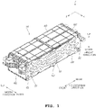
- FIG. 1 is a perspective view of a battery module included in a battery pack according to one form of the present disclosure, when viewed from the top
- FIG. 2 is a perspective view of the battery module illustrated in FIG. 1 , when viewed from the bottom
- FIG. 3 is an exploded perspective view of the battery module illustrated in FIG. 1 .
- a surface direction in which an upper cover 40 is installed is expressed as upward and a surface direction facing the upward direction is expressed as downward, and a direction corresponding to the distance between a surface on which the upper cover 40 is installed and a surface facing the surface is expressed as a height direction.
- Such expressions may follow a typical object size expression scheme, and the width direction, the length direction, and the height direction may have mutual orthogonal relationships.
- the battery module 10 applied to a battery pack may be configured to include the plurality of battery cells 110 mutually laminated in the width direction, the pair of end plates 20 being in surface contact with both ends of a laminated structure 100 in the width direction, respectively, in which the plurality of battery cells 110 are laminated, a pair of busbar assemblies 30 disposed at both ends in the length direction of the structure 100 in which the plurality of battery cells 110 having electrodes mutually joined are laminated, the upper cover 40 configured to cover an upper part of the structure 100, in which the plurality of battery cells 110 are laminated, in the height direction, a first clamp 51 extending in the width direction from an upper part of the upper cover 40 and having both ends joined to the pair of end plates 20, respectively, and a second clamp 52 extending in the width direction from a lower part of the structure 100 in which the plurality of battery cells 110 are laminated and having both ends joined to the two end plates 20, respectively.
- the battery module according to one form of the present disclosure may include front and rear covers 60 configured to cover the structure 100, in which the battery cells 110 are laminated, in the length direction from the outsides of the busbar assemblies 30, respectively.
- the battery cell 110 may be implemented in the form of a pouch having electrodes at both ends thereof in the length direction, and one battery cell laminated structure 100 may be formed by laminating the plurality of battery cells 110 in the width direction.
- a surface pressure pad having compression elasticity may be provided between the battery cells 110 to maintain a constant surface pressure and to absorb expansion of the battery cells 110 during swelling of the battery cells 110, and a double-sided tape or a hot melt may be interposed between the battery cells 110 for joining between the battery cells 110.
- the pair of end plates 20 may be disposed to come in surface contact with surfaces located at both ends in the lamination direction of the battery cell laminated structure 100, that is, exposed surfaces of the outermost battery cell among the plurality of battery cells 110 forming the laminated structure 100.
- the pair of end plates 20 are elements which are mutually maintained at a constant interval, inhibit the deformation in the battery module through their own stiffness in case that swelling of the battery cells 110 occurs, and uniformly maintain the surface pressure between the laminated battery cells 110. Accordingly, the end plates 20 should have stiffness enough to inhibit the deformation in the battery module while maintaining the surface contact with the battery cells 110, and an additional means for uniform surface pressure may be provided in the end plates 20.
- the busbar assembly 30 may include busbars disposed in front and at the rear of the battery cell laminated structure 100 and configured to form an electrical connection between electrodes of the battery cells 110 disposed in front and at the rear of the laminated structure.
- the busbar assembly 30 may include the busbars of a metal material, joined to the electrodes of the battery cells 110, in an injection structure of an insulation material like plastics, and may be provided with a connector having pins connected to the busbars, so that the voltages of the battery cells 110 may be externally detected.
- the busbar provided in the busbar assembly 30 may have an extension part extending for connection with another external battery cell module or terminal, and the extension part may be exposed through the front and rear covers 60.
- the first clamp 51 and the second clamp 52 may extend in the width direction from upper and lower parts of the laminated structure 100, and both ends thereof are joined to the pair of end plates 20, so that the distance between the two end plates 20 may be maintained constantly.
- the first clamp 51 and the second clamp 52 are joined in the center parts in the length direction of the two end plates 20, respectively, the first clamp 51 and the second clamp 52 restrain the center parts in the length direction of the two end plates 20 during the swelling of the battery cell 110, and thus can inhibit the battery module 10 from swelling.
- the front and rear covers 60 can cover the surfaces corresponding to the front and the rear of the laminated structure 100 in the length direction of the battery cell laminated structure 100.
- the front and rear covers 60 are installed in symmetrical positions of the battery module 10 and have substantially the same configuration, and thus they are denoted by the same reference numeral.
- the front and rear covers 60 may include through-holes for exposing the elements that should be exposed out of the battery module (e.g., the extension parts of the busbars that should be exposed for an external electrical connection and the connectors having pins electrically connected to the busbars) among the elements provided in the busbar assemblies 30.
- FIG. 4 is a view illustrating in more detail a portion in which the front cover or rear cover is assembled to the battery module illustrated in FIG. 1 .
- each of the front and rear covers 60 of the battery module may include a cover surface 601 facing the front and rear surfaces of the laminated structure 100, and a first fastening part 61 and a second fastening part 62 respectively projecting from both ends in the width direction of the cover surface 601 more than both sides of the laminated structure 100.
- the first fastening part 61 and the second fastening part are elements provided to fasten a battery module to another adjacent battery module in case of configuring the battery pack, and the fastening part 61 may include a through-hole 611 penetrated in an up/down direction, and an insert nut 612 provided inside the through-hole 611, the fastening part 62 may include a through-hole 621 penetrated in an up/down direction and a bush 622 provided inside the through-hole 621.
- each of the front and rear covers 60 may include a seat part 67 projecting forward or rearward from the cover surface 601 and configured to expose an extension part 32 of the busbar, installed in the busbar assembly 30 inside the battery module 10, out of the battery module 10 and seat the extension part 32 therein, and a connector hole 68 formed in the cover surface 601 and configured to expose a connector 35, installed on the busbar assembly 30, to an outside.
- each of the front and rear covers 60 may include an extension structure part L connected from the cover surface 601 to the projecting fastening parts 61, 62, and the extension structure part L may be formed of a lattice structure having a hollow. If an impact is applied to the battery module 10, the extension structure part L may absorb the impact to secure stiffness.
- the extension structure part L may have a shape obliquely extending from the center part of the cover surface 601 to the respective fastening parts 61, 62 at a height corresponding to the two fastening parts 61, 62.
- each of the front and rear covers 60 may come in contact with the end plate 20.
- Side parts of the end plates 20, a second cover and a third cover 30 may be mutually combined through a bolt 21.
- the bolt 21 may be combined with both ends of one long nut disposed inside the cover 60.
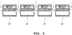
- FIG. 5 is a front view explaining the concept of configuring a battery module assembly through mutual fastening of battery modules according to one form of the present disclosure
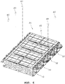
- FIG. 6 is a perspective view illustrating a battery module assembly configured through fastening of a plurality of battery modules according to one form of the present disclosure
- FIG. 7 is a plan view of the battery module assembly illustrated in FIG. 6 .
- a battery pack according to one form of the present disclosure may be produced in a manner that a battery module assembly, which is a structure formed by fastening a predetermined number of battery modules 10 to one another, is first produced, and then the produced battery module assembly is mounted into a mounting area of a pre-prepared case.
- a battery module assembly 80 may be produced by aligning and mutually fastening a plurality of battery modules 10 (four battery modules in an example illustrated in FIGS. 5 to 7 ) in a lateral direction (direction in which the battery cells are laminated in the battery module).
- alignment of the battery modules in the lateral direction means alignment of the battery modules in a direction in which battery cells are laminated in the battery modules. This is to make the surface pressure act even between the battery modules during swelling of the battery cells.
- the fastening parts 61, 62 of the neighboring modules may be disposed to overlap each other in an up/down direction, and the through-holes of the respective fastening parts may be disposed side by side in an up/down direction, so that one fastening member 65 may be inserted into the through-holes disposed side by side.
- the first fastening part 61 and the second fastening part 62 which are formed on the cover 60 of the battery module 10, are formed to have a height difference H so that the fastening parts of the neighboring battery modules can be disposed side-by-side.
- the height of a lower end of one fastening part 62 is substantially equal to the height of an upper end of the other fastening part 61 so that the fastening parts of the two battery modules, which are disposed to overlap each other, contact each other in an up/down direction.
- FIG. 8 is a view illustrating an example of a fastening member used for fastening between battery modules when manufacturing a battery module assembly of a battery pack according to one form of the present disclosure.
- a hollow bolt 65 having a hollow may be used for fastening between the battery modules.
- the hollow bolt 65 is a bolt including a through-hole formed in the center part in a bolt fastening direction, and is a bolt produced to be able to install other members through the through-hole.
- the hollow bolt 35 will be able to be used for the purpose of fixing the battery module assembly itself to the case of the battery pack through insertion of an additional bolt into the through-hole of the hollow bolt 35. That is, the hollow bolt 35 may be used to mutually fasten the battery modules, and the battery module assembly is able to be fixed to the case through penetration of the additional bolt into the through-hole of the hollow bolt. According to the structure using the hollow bolt 35, the battery module fastening and the battery assembly case fastening can be performed together in one fastening space without separately providing a space for the fastening between the battery modules and the fastening of the case of the battery assembly, and thus the spatial utility can be improved.
- FIG. 9 is a plan view of a battery pack according to one form of the present disclosure
- FIG. 10 is a perspective view illustrating a state in which a battery module assembly is fastened to a lower case in a battery pack according to one form of the present disclosure.
- a battery pack 90 may include a case 900 including a lower panel 910, a vertical member 920 and horizontal members 930 dividing an upper surface of the lower panel 910 into a plurality of area, and side members 940 disposed at a border part; and a battery module assembly 80 seated on the upper surface of the lower panel 910 of the case 900 and fixed to be fastened to the horizontal member 930.
- the battery pack 90 may be produced by first producing the battery module assembly 80 through fastening of a predetermined number of battery modules 10 and by seating, fastening, and fixing the produced battery module assembly 80 into the case 900.
- the fastening part which is used to perform the fastening between the battery modules in the battery module assembly, may also be used to fasten the battery module assembly into the case.
- the battery module assembly 80 may be seated on the case so that the fastening parts of the respective battery modules 10 are disposed on the horizontal members 930, and the vertical member 920 and the side members 940 are aligned in a direction parallel to the lamination surface of the laminated battery cells.
- the several members 920, 930, 940 may be used as a means for providing the stiffness of the battery case itself and fastening the battery module assembly 80 at the same time. Further, the members 920, 930, 940 may provide paths through which wirings necessary in the battery pack pass.
- the battery module assembly 80 in the process of producing the battery module assembly 80, may be fastened to the case 900 using the first fastening part 61 and the second fastening part 62 that mutually fasten the battery modules 10.
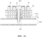
- FIG. 11 is a cross-sectional view illustrating in more detail a fastening structure between a battery module assembly and a case according to one form of the present disclosure, and illustrates a cross-section of areas corresponding to the reference numeral "A" illustrated in FIG. 10 .
- A denotes a fastening part in which two battery modules are mutually fastened in the battery module assembly 80.
- the reference numeral "B” of FIG. 10 illustrates a fastening part located at the outermost part of the battery module assembly 80, and corresponds to the second fastening part 62 located in a relatively higher position than the position of the first fastening part 61.
- the hollow bolt 65 may be fastened to the overlapping through-holes, and thus the two battery modules may be mutually fastened. That is, the fastening may be formed in a manner that the hollow bolt 65 is combined with the insert nut 612 inside the through-hole located on the lower part through penetration of the bush 622 inside the through-hole located on the upper part. As the fastening between the battery modules 10 is formed by the hollow bolt 65 as described above, the battery module assembly can be produced.
- the bush 622 may be made of a metal material in order to inhibit the cover mainly made of a plastic material from being damaged by a fastening force.
- the bush 622 may be made of a rubber material to inhibit the damage of the fastening structure or the occurrence of noise through absorption of an external vibration applied in a state where the battery modules 10 are mutually fastened.
- the battery module assembly including the plurality of battery modules 10 mutually fastened by the hollow bolt 65 may be fastened by the horizontal members 930 of the case 900 and may be seated on the case.
- a fastening hole into which a fastening member can be inserted may be formed on the horizontal member 930, and a pop nut 901 may be inserted into the fastening hole.
- the battery module assembly 80 including the plurality of battery modules 10 can be seated and mounted on the case.
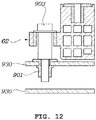
- FIG. 12 is a cross-sectional view illustrating in more detail a fastening structure between a battery module assembly and a case according to one form of the present disclosure, and illustrates a cross-section of areas corresponding to a reference numeral "B" illustrated in FIG. 10 .
- the fastening parts formed on both sides of the cover 60 of the battery module have different heights, and if the fastening part (first fastening part 61) having a relatively low height is mounted in a state where the fastening part comes in contact with the horizontal members 930, one (second fastening part 62) of the fastening parts located in the outermost position of the battery module assembly becomes spaced apart from the upper surface of the horizontal member 930 at a predetermined interval.
- a shoulder bolt 903 may be applied to the outermost fastening part located to be spaced apart from the upper surface of the horizontal member 930 at the predetermined interval.
- the shoulder bolt 903 is a bolt capable of constantly configuring the interval between a head part of the bolt and the fastening part. That is, in one form of the present disclosure, it is possible to apply the shoulder bolt 903 including a shoulder part that is not inserted into the fastening hole as long as the distance from the lower end of the head to the fastening part 62 and the upper surface of the horizontal member 930. Of course, the pop nut 901 for fastening of the shoulder bolt 903 may be inserted into the fastening hole.
- an additional end plate may be provided so as to improve the surface pressure characteristic during a cell swelling through applying of the pressure to the seated battery module assembly.
- FIG. 13 is a perspective view explaining the concept of installing a case end module of a battery pack according to one form of the present disclosure
- FIG. 14 is a perspective view illustrating in more detail the state in which the case end module of FIG. 13 is installed.
- case end modules 950 may be installed to face the battery module assembly vertically to a direction in which the battery modules in the battery module assembly are aligned, that is, a direction in which the battery cells in the battery module are laminated. That is, the case end plates 950 may be disposed in line with the side surface of the battery module assembly and may be disposed to face the side surface of the battery module assembly.
- the case end plate 950 may have a first surface disposed to face the side surface of the battery module assembly and a second surface bent opposite to a direction, in which the battery module assembly is located, from the first surface.
- the second surface may be fastened to the upper surface of the vertical member 920', and the first surface may be fastened to the horizontal member 930.
- the vertical member 920' may be a member, which is installed in line with the vertical member 920 illustrated in FIG. 9 , but is formed with a height lower than the height of the vertical member 920 between the two horizontal members 930.
- FIG. 15 is a view illustrating a cross-section of a second surface of the case end module illustrated in FIG. 14 fastened to a vertical member.
- the second surface of the case end module 950 may be fastened to the upper part of the vertical member 920' by a bolt 904.
- the pop nut 901 may be inserted into the fastening hole of the upper surface of the vertical member 920' to which the bolt 904 is fastened.
- FIG. 16 is a view illustrating a cross-section of a first surface of the case end module illustrated in FIG. 14 fastened to a horizontal member.
- the side end part of the first surface of the case end plate 950 may be fastened to the horizontal member 930 together with the outermost fastening part of the battery module assembly.
- the side end part of the case end module 950 may be bent and disposed in line with the fastening part 61 of the battery module assembly, and the guide pin 905 may be commonly inserted into the fastening hole formed on the side end part of the first surface of the case end plate 950, the through-hole of the fastening part 61, and the fastening hole of the horizontal member to perform location regulation.
- a screw thread for fastening may be formed at the lower end and the upper end of the guide pin 930, and a taper structure, which is widened as going to its lower part, may be formed in the center part of the guide pin 930, thereby an excessive insertion can be regulated.
- the case end plate 950 and the battery module assembly may be fixed to the horizontal member 930.
- FIGS. 14 and 15 illustrate an example in which the second surface of the case end plate 950 is fixed to a separate vertical member, it may also be connected to another configuration capable of substantially serving as the vertical member provided in the case as another example.
- any member that is disposed in a vertical direction and is formed in the vertical direction capable of forming a fastening hole, such as an extruded material provided in the side of the case may be used to fasten the second surface of the case end plate 950.
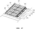
- FIG. 17 is a perspective view illustrating a state in which a fastening structure for vehicle attachment is applied in a state in which a battery module assembly is seated in a case in a battery pack according to one form of the present disclosure.
- an extension structure part L formed on the front and rear covers 60 of the battery module applied to the battery pack may have a shape obliquely extending from the center part of the cover surface 601 to the respective fastening parts 61, 62 at the height corresponding to the two fastening parts 61, 62. Since the extension structure part L having such a shape is formed, an empty space S may be formed between the two fastening parts 61, 62. This empty space S may be used to install therein a fastening structure for mutually fastening the battery and the vehicle or to pass therethrough various wirings connected to the battery modules.
- the present disclosure is not limited to such a structure in which the covers 60 having substantially the same structure are disposed both in front and in the rear of the battery modules. That is, in another form of the present disclosure, a cover having the above-described shape and fastening structure may be disposed only in front or in the rear of the battery modules 10, and a cover having a completely different structure may be disposed in the other of the front or the rear of the battery modules.
- the present disclosure also provides a method for manufacturing a battery pack.
- the method for manufacturing a battery pack according to one form of the present disclosure may include first producing a battery module assembly 80 by mutually fastening the battery module 10 as described above and combining the produced battery module assembly 80 with a case. Such steps have been described in detail through the accompanying drawings.
- the method for manufacturing a battery pack it is possible to fix the battery module assembly into the member 930 of the case 900 by applying the overlapping fastening parts 61 and 62 combining the battery modules with one another in the battery module assembly as additional fastening members, and after installing the battery module assembly, it is possible to provide the surface pressure in the unit of a battery module assembly by additionally installing the case end plate.
- the battery pack and the manufacturing method thereof according to various forms of the present disclosure, it is possible to easily produce the battery module assembly through fastening between the battery modules by applying the fastening structure using the fastening parts formed on the front and rear covers of the battery module in the battery assembly.
- the seating and fastening of the case can be performed in the unit of the produced battery module assembly, spatial utility for packaging of the battery pack can be improved, and the battery pack can be advantageously standardized and publicized.
- the fastening part is formed to fasten the battery modules in the direction in which the battery cells are laminated in the battery module, the surface pressure performance can be improved through a close contact structure between the battery modules in the battery assembly, and the surface pressure performance can be improved even in the unit of the battery assembly through additional installation of the case end plate in the case.
Landscapes
- Chemical & Material Sciences (AREA)
- Chemical Kinetics & Catalysis (AREA)
- Electrochemistry (AREA)
- General Chemical & Material Sciences (AREA)
- Engineering & Computer Science (AREA)
- General Engineering & Computer Science (AREA)
- Mechanical Engineering (AREA)
- Life Sciences & Earth Sciences (AREA)
- Sustainable Development (AREA)
- Sustainable Energy (AREA)
- Power Engineering (AREA)
- Transportation (AREA)
- Aviation & Aerospace Engineering (AREA)
- Battery Mounting, Suspending (AREA)
Applications Claiming Priority (1)
| Application Number | Priority Date | Filing Date | Title |
|---|---|---|---|
| KR1020200175421A KR20220085396A (ko) | 2020-12-15 | 2020-12-15 | 배터리 팩 및 이 배터리 팩의 제조 방법 |
Publications (1)
| Publication Number | Publication Date |
|---|---|
| EP4016715A1 true EP4016715A1 (fr) | 2022-06-22 |
Family
ID=77563966
Family Applications (1)
| Application Number | Title | Priority Date | Filing Date |
|---|---|---|---|
| EP21193976.4A Pending EP4016715A1 (fr) | 2020-12-15 | 2021-08-31 | Bloc-batterie et son procédé de commande |
Country Status (4)
| Country | Link |
|---|---|
| US (1) | US20220190430A1 (fr) |
| EP (1) | EP4016715A1 (fr) |
| KR (1) | KR20220085396A (fr) |
| CN (1) | CN114639905A (fr) |
Families Citing this family (4)
| Publication number | Priority date | Publication date | Assignee | Title |
|---|---|---|---|---|
| KR20220026384A (ko) * | 2020-08-25 | 2022-03-04 | 현대자동차주식회사 | 배터리가 결합된 차체 |
| KR20230067150A (ko) * | 2021-11-09 | 2023-05-16 | 현대자동차주식회사 | 차량의 배터리팩 케이스 |
| WO2024117690A1 (fr) * | 2022-12-02 | 2024-06-06 | 주식회사 엘지에너지솔루션 | Bloc-batterie |
| EP4425670A1 (fr) * | 2022-12-23 | 2024-09-04 | LG Energy Solution, Ltd. | Bloc-batterie |
Citations (3)
| Publication number | Priority date | Publication date | Assignee | Title |
|---|---|---|---|---|
| EP2339664A1 (fr) * | 2009-12-23 | 2011-06-29 | SB LiMotive Co., Ltd. | Bloc-batterie |
| EP3567650A1 (fr) * | 2017-04-07 | 2019-11-13 | LG Chem, Ltd. | Bloc-batterie ayant une structure de module de batterie extensible |
| US20200176747A1 (en) * | 2017-07-28 | 2020-06-04 | Panasonic Intellectual Property Management Co., Ltd. | Linked battery module and linked battery pack |
Family Cites Families (11)
| Publication number | Priority date | Publication date | Assignee | Title |
|---|---|---|---|---|
| JP2008282639A (ja) * | 2007-05-10 | 2008-11-20 | Calsonic Kansei Corp | バッテリ構造 |
| KR101637266B1 (ko) | 2010-12-06 | 2016-07-07 | 현대자동차 주식회사 | 전기 자동차의 배터리팩 지지 구조 |
| JP5513445B2 (ja) * | 2011-06-08 | 2014-06-04 | 本田技研工業株式会社 | 車両用電源装置 |
| JP2014120346A (ja) * | 2012-12-17 | 2014-06-30 | Denso Corp | 組電池 |
| US10329008B2 (en) * | 2016-06-24 | 2019-06-25 | The Boeing Company | Fluid-tight mechanical fastening system and associated structural assembly |
| CN114583369A (zh) * | 2016-11-09 | 2022-06-03 | Cps 科技控股有限公司 | 电池包 |
| KR102255495B1 (ko) * | 2017-07-18 | 2021-05-24 | 주식회사 엘지에너지솔루션 | 배터리 모듈, 이를 포함하는 배터리 팩 및 자동차 |
| KR102575355B1 (ko) | 2018-04-26 | 2023-09-07 | 현대자동차주식회사 | 차량용 배터리 케이스 |
| KR102378374B1 (ko) * | 2018-06-18 | 2022-03-25 | 주식회사 엘지에너지솔루션 | 버스바를 구비한 배터리 모듈 및 배터리 팩 |
| DE102019111769A1 (de) * | 2019-05-07 | 2020-11-12 | Dr. Ing. H.C. F. Porsche Aktiengesellschaft | Batteriemodul einer Hochvolt-Batterie für ein Elektrofahrzeug |
| WO2021015461A1 (fr) * | 2019-07-19 | 2021-01-28 | 주식회사 엘지화학 | Module de batterie et bloc-batterie le comprenant |
-
2020
- 2020-12-15 KR KR1020200175421A patent/KR20220085396A/ko unknown
-
2021
- 2021-08-20 US US17/407,721 patent/US20220190430A1/en active Pending
- 2021-08-31 EP EP21193976.4A patent/EP4016715A1/fr active Pending
- 2021-09-29 CN CN202111154265.3A patent/CN114639905A/zh active Pending
Patent Citations (3)
| Publication number | Priority date | Publication date | Assignee | Title |
|---|---|---|---|---|
| EP2339664A1 (fr) * | 2009-12-23 | 2011-06-29 | SB LiMotive Co., Ltd. | Bloc-batterie |
| EP3567650A1 (fr) * | 2017-04-07 | 2019-11-13 | LG Chem, Ltd. | Bloc-batterie ayant une structure de module de batterie extensible |
| US20200176747A1 (en) * | 2017-07-28 | 2020-06-04 | Panasonic Intellectual Property Management Co., Ltd. | Linked battery module and linked battery pack |
Also Published As
| Publication number | Publication date |
|---|---|
| CN114639905A (zh) | 2022-06-17 |
| US20220190430A1 (en) | 2022-06-16 |
| KR20220085396A (ko) | 2022-06-22 |
Similar Documents
| Publication | Publication Date | Title |
|---|---|---|
| EP4016715A1 (fr) | Bloc-batterie et son procédé de commande | |
| KR20220052183A (ko) | 배터리 모듈 및 이를 포함하는 배터리 팩 | |
| JP7037007B2 (ja) | 拡張型バッテリーモジュール構造を有するバッテリーパック | |
| KR101326196B1 (ko) | 콤팩트한 구조의 전지팩 | |
| KR101909215B1 (ko) | 전지 서브 모듈 캐리어, 전지 서브 모듈, 전지 시스템 및 자동차 | |
| JP6109314B2 (ja) | バスバーアセンブリを含む電池モジュール及びそれを含む電池パック | |
| KR100921346B1 (ko) | 중대형 전지모듈 및 전지모듈 어셈블리 | |
| KR102250204B1 (ko) | 배터리 모듈, 이러한 배터리 모듈을 포함하는 배터리 팩 및 이러한 배터리 팩을 포함하는 자동차 | |
| KR20130122323A (ko) | 배터리 팩 및 이를 포함하는 배터리 모듈 | |
| KR102492310B1 (ko) | 커버 구조물을 포함하는 배터리 팩 및 전자 디바이스 및 자동차 | |
| KR20200064761A (ko) | 배터리 모듈을 포함하는 배터리 팩 | |
| US11817602B2 (en) | Battery module and battery pack including the same | |
| CN103299451B (zh) | 包括多个棱柱形的蓄能单元的蓄能模块和蓄能模块的端板的制造方法 | |
| KR20220041470A (ko) | 배터리 모듈 및 이를 포함하는 배터리 팩 | |
| KR20070104692A (ko) | 중대형 전지모듈 제조용 프레임 부재 | |
| JP2024095749A (ja) | 電池パック及び電気自動車 | |
| KR20220052184A (ko) | 배터리 모듈 및 이를 포함하는 배터리 팩 | |
| KR20220012038A (ko) | 배터리 팩 및 이를 포함하는 자동차 | |
| KR20210036132A (ko) | 전지팩 및 그 제조 방법 | |
| KR20220045353A (ko) | 배터리 모듈 | |
| KR20220052182A (ko) | 배터리 모듈의 제조 방법 | |
| KR102634392B1 (ko) | 연료 전지 스택 모듈 | |
| JP6973180B2 (ja) | 電池パック | |
| KR101859684B1 (ko) | 버스 바 어셈블리를 포함하는 전지모듈 및 이를 포함하는 전지팩 | |
| JP5452204B2 (ja) | 電池モジュール |
Legal Events
| Date | Code | Title | Description |
|---|---|---|---|
| PUAI | Public reference made under article 153(3) epc to a published international application that has entered the european phase |
Free format text: ORIGINAL CODE: 0009012 |
|
| STAA | Information on the status of an ep patent application or granted ep patent |
Free format text: STATUS: THE APPLICATION HAS BEEN PUBLISHED |
|
| AK | Designated contracting states |
Kind code of ref document: A1 Designated state(s): AL AT BE BG CH CY CZ DE DK EE ES FI FR GB GR HR HU IE IS IT LI LT LU LV MC MK MT NL NO PL PT RO RS SE SI SK SM TR |
|
| STAA | Information on the status of an ep patent application or granted ep patent |
Free format text: STATUS: REQUEST FOR EXAMINATION WAS MADE |
|
| 17P | Request for examination filed |
Effective date: 20221215 |
|
| RBV | Designated contracting states (corrected) |
Designated state(s): AL AT BE BG CH CY CZ DE DK EE ES FI FR GB GR HR HU IE IS IT LI LT LU LV MC MK MT NL NO PL PT RO RS SE SI SK SM TR |
|
| P01 | Opt-out of the competence of the unified patent court (upc) registered |
Effective date: 20230504 |