EP4016189B1 - Image forming apparatus - Google Patents
Image forming apparatus Download PDFInfo
- Publication number
- EP4016189B1 EP4016189B1 EP21213042.1A EP21213042A EP4016189B1 EP 4016189 B1 EP4016189 B1 EP 4016189B1 EP 21213042 A EP21213042 A EP 21213042A EP 4016189 B1 EP4016189 B1 EP 4016189B1
- Authority
- EP
- European Patent Office
- Prior art keywords
- chart
- recording material
- secondary transfer
- image
- voltage
- Prior art date
- Legal status (The legal status is an assumption and is not a legal conclusion. Google has not performed a legal analysis and makes no representation as to the accuracy of the status listed.)
- Active
Links
Images


Classifications
-
- G—PHYSICS
- G03—PHOTOGRAPHY; CINEMATOGRAPHY; ANALOGOUS TECHNIQUES USING WAVES OTHER THAN OPTICAL WAVES; ELECTROGRAPHY; HOLOGRAPHY
- G03G—ELECTROGRAPHY; ELECTROPHOTOGRAPHY; MAGNETOGRAPHY
- G03G15/00—Apparatus for electrographic processes using a charge pattern
- G03G15/14—Apparatus for electrographic processes using a charge pattern for transferring a pattern to a second base
- G03G15/16—Apparatus for electrographic processes using a charge pattern for transferring a pattern to a second base of a toner pattern, e.g. a powder pattern, e.g. magnetic transfer
- G03G15/1665—Apparatus for electrographic processes using a charge pattern for transferring a pattern to a second base of a toner pattern, e.g. a powder pattern, e.g. magnetic transfer by introducing the second base in the nip formed by the recording member and at least one transfer member, e.g. in combination with bias or heat
-
- G—PHYSICS
- G03—PHOTOGRAPHY; CINEMATOGRAPHY; ANALOGOUS TECHNIQUES USING WAVES OTHER THAN OPTICAL WAVES; ELECTROGRAPHY; HOLOGRAPHY
- G03G—ELECTROGRAPHY; ELECTROPHOTOGRAPHY; MAGNETOGRAPHY
- G03G15/00—Apparatus for electrographic processes using a charge pattern
- G03G15/50—Machine control of apparatus for electrographic processes using a charge pattern, e.g. regulating differents parts of the machine, multimode copiers, microprocessor control
- G03G15/5054—Machine control of apparatus for electrographic processes using a charge pattern, e.g. regulating differents parts of the machine, multimode copiers, microprocessor control by measuring the characteristics of an intermediate image carrying member or the characteristics of an image on an intermediate image carrying member, e.g. intermediate transfer belt or drum, conveyor belt
-
- G—PHYSICS
- G03—PHOTOGRAPHY; CINEMATOGRAPHY; ANALOGOUS TECHNIQUES USING WAVES OTHER THAN OPTICAL WAVES; ELECTROGRAPHY; HOLOGRAPHY
- G03G—ELECTROGRAPHY; ELECTROPHOTOGRAPHY; MAGNETOGRAPHY
- G03G15/00—Apparatus for electrographic processes using a charge pattern
- G03G15/01—Apparatus for electrographic processes using a charge pattern for producing multicoloured copies
- G03G15/0142—Structure of complete machines
- G03G15/0178—Structure of complete machines using more than one reusable electrographic recording member, e.g. one for every monocolour image
- G03G15/0189—Structure of complete machines using more than one reusable electrographic recording member, e.g. one for every monocolour image primary transfer to an intermediate transfer belt
-
- G—PHYSICS
- G03—PHOTOGRAPHY; CINEMATOGRAPHY; ANALOGOUS TECHNIQUES USING WAVES OTHER THAN OPTICAL WAVES; ELECTROGRAPHY; HOLOGRAPHY
- G03G—ELECTROGRAPHY; ELECTROPHOTOGRAPHY; MAGNETOGRAPHY
- G03G15/00—Apparatus for electrographic processes using a charge pattern
- G03G15/02—Apparatus for electrographic processes using a charge pattern for laying down a uniform charge, e.g. for sensitising; Corona discharge devices
- G03G15/0266—Arrangements for controlling the amount of charge
-
- G—PHYSICS
- G03—PHOTOGRAPHY; CINEMATOGRAPHY; ANALOGOUS TECHNIQUES USING WAVES OTHER THAN OPTICAL WAVES; ELECTROGRAPHY; HOLOGRAPHY
- G03G—ELECTROGRAPHY; ELECTROPHOTOGRAPHY; MAGNETOGRAPHY
- G03G15/00—Apparatus for electrographic processes using a charge pattern
- G03G15/14—Apparatus for electrographic processes using a charge pattern for transferring a pattern to a second base
- G03G15/16—Apparatus for electrographic processes using a charge pattern for transferring a pattern to a second base of a toner pattern, e.g. a powder pattern, e.g. magnetic transfer
- G03G15/1605—Apparatus for electrographic processes using a charge pattern for transferring a pattern to a second base of a toner pattern, e.g. a powder pattern, e.g. magnetic transfer using at least one intermediate support
-
- G—PHYSICS
- G03—PHOTOGRAPHY; CINEMATOGRAPHY; ANALOGOUS TECHNIQUES USING WAVES OTHER THAN OPTICAL WAVES; ELECTROGRAPHY; HOLOGRAPHY
- G03G—ELECTROGRAPHY; ELECTROPHOTOGRAPHY; MAGNETOGRAPHY
- G03G15/00—Apparatus for electrographic processes using a charge pattern
- G03G15/14—Apparatus for electrographic processes using a charge pattern for transferring a pattern to a second base
- G03G15/16—Apparatus for electrographic processes using a charge pattern for transferring a pattern to a second base of a toner pattern, e.g. a powder pattern, e.g. magnetic transfer
- G03G15/163—Apparatus for electrographic processes using a charge pattern for transferring a pattern to a second base of a toner pattern, e.g. a powder pattern, e.g. magnetic transfer using the force produced by an electrostatic transfer field formed between the second base and the electrographic recording member, e.g. transfer through an air gap
- G03G15/1635—Apparatus for electrographic processes using a charge pattern for transferring a pattern to a second base of a toner pattern, e.g. a powder pattern, e.g. magnetic transfer using the force produced by an electrostatic transfer field formed between the second base and the electrographic recording member, e.g. transfer through an air gap the field being produced by laying down an electrostatic charge behind the base or the recording member, e.g. by a corona device
- G03G15/1645—Arrangements for controlling the amount of charge
-
- G—PHYSICS
- G03—PHOTOGRAPHY; CINEMATOGRAPHY; ANALOGOUS TECHNIQUES USING WAVES OTHER THAN OPTICAL WAVES; ELECTROGRAPHY; HOLOGRAPHY
- G03G—ELECTROGRAPHY; ELECTROPHOTOGRAPHY; MAGNETOGRAPHY
- G03G15/00—Apparatus for electrographic processes using a charge pattern
- G03G15/14—Apparatus for electrographic processes using a charge pattern for transferring a pattern to a second base
- G03G15/16—Apparatus for electrographic processes using a charge pattern for transferring a pattern to a second base of a toner pattern, e.g. a powder pattern, e.g. magnetic transfer
- G03G15/1665—Apparatus for electrographic processes using a charge pattern for transferring a pattern to a second base of a toner pattern, e.g. a powder pattern, e.g. magnetic transfer by introducing the second base in the nip formed by the recording member and at least one transfer member, e.g. in combination with bias or heat
- G03G15/167—Apparatus for electrographic processes using a charge pattern for transferring a pattern to a second base of a toner pattern, e.g. a powder pattern, e.g. magnetic transfer by introducing the second base in the nip formed by the recording member and at least one transfer member, e.g. in combination with bias or heat at least one of the recording member or the transfer member being rotatable during the transfer
- G03G15/1675—Apparatus for electrographic processes using a charge pattern for transferring a pattern to a second base of a toner pattern, e.g. a powder pattern, e.g. magnetic transfer by introducing the second base in the nip formed by the recording member and at least one transfer member, e.g. in combination with bias or heat at least one of the recording member or the transfer member being rotatable during the transfer with means for controlling the bias applied in the transfer nip
-
- G—PHYSICS
- G03—PHOTOGRAPHY; CINEMATOGRAPHY; ANALOGOUS TECHNIQUES USING WAVES OTHER THAN OPTICAL WAVES; ELECTROGRAPHY; HOLOGRAPHY
- G03G—ELECTROGRAPHY; ELECTROPHOTOGRAPHY; MAGNETOGRAPHY
- G03G15/00—Apparatus for electrographic processes using a charge pattern
- G03G15/50—Machine control of apparatus for electrographic processes using a charge pattern, e.g. regulating differents parts of the machine, multimode copiers, microprocessor control
- G03G15/5033—Machine control of apparatus for electrographic processes using a charge pattern, e.g. regulating differents parts of the machine, multimode copiers, microprocessor control by measuring the photoconductor characteristics, e.g. temperature, or the characteristics of an image on the photoconductor
- G03G15/5041—Detecting a toner image, e.g. density, toner coverage, using a test patch
-
- G—PHYSICS
- G03—PHOTOGRAPHY; CINEMATOGRAPHY; ANALOGOUS TECHNIQUES USING WAVES OTHER THAN OPTICAL WAVES; ELECTROGRAPHY; HOLOGRAPHY
- G03G—ELECTROGRAPHY; ELECTROPHOTOGRAPHY; MAGNETOGRAPHY
- G03G15/00—Apparatus for electrographic processes using a charge pattern
- G03G15/50—Machine control of apparatus for electrographic processes using a charge pattern, e.g. regulating differents parts of the machine, multimode copiers, microprocessor control
- G03G15/5062—Machine control of apparatus for electrographic processes using a charge pattern, e.g. regulating differents parts of the machine, multimode copiers, microprocessor control by measuring the characteristics of an image on the copy material
-
- G—PHYSICS
- G03—PHOTOGRAPHY; CINEMATOGRAPHY; ANALOGOUS TECHNIQUES USING WAVES OTHER THAN OPTICAL WAVES; ELECTROGRAPHY; HOLOGRAPHY
- G03G—ELECTROGRAPHY; ELECTROPHOTOGRAPHY; MAGNETOGRAPHY
- G03G15/00—Apparatus for electrographic processes using a charge pattern
- G03G15/65—Apparatus which relate to the handling of copy material
- G03G15/6588—Apparatus which relate to the handling of copy material characterised by the copy material, e.g. postcards, large copies, multi-layered materials, coloured sheet material
- G03G15/6594—Apparatus which relate to the handling of copy material characterised by the copy material, e.g. postcards, large copies, multi-layered materials, coloured sheet material characterised by the format or the thickness, e.g. endless forms
-
- G—PHYSICS
- G03—PHOTOGRAPHY; CINEMATOGRAPHY; ANALOGOUS TECHNIQUES USING WAVES OTHER THAN OPTICAL WAVES; ELECTROGRAPHY; HOLOGRAPHY
- G03G—ELECTROGRAPHY; ELECTROPHOTOGRAPHY; MAGNETOGRAPHY
- G03G2215/00—Apparatus for electrophotographic processes
- G03G2215/00362—Apparatus for electrophotographic processes relating to the copy medium handling
- G03G2215/00443—Copy medium
- G03G2215/00451—Paper
- G03G2215/00464—Non-standard format
- G03G2215/00468—Large sized, e.g. technical plans
-
- G—PHYSICS
- G03—PHOTOGRAPHY; CINEMATOGRAPHY; ANALOGOUS TECHNIQUES USING WAVES OTHER THAN OPTICAL WAVES; ELECTROGRAPHY; HOLOGRAPHY
- G03G—ELECTROGRAPHY; ELECTROPHOTOGRAPHY; MAGNETOGRAPHY
- G03G2215/00—Apparatus for electrophotographic processes
- G03G2215/00362—Apparatus for electrophotographic processes relating to the copy medium handling
- G03G2215/00535—Stable handling of copy medium
- G03G2215/00556—Control of copy medium feeding
- G03G2215/00569—Calibration, test runs, test prints
-
- G—PHYSICS
- G03—PHOTOGRAPHY; CINEMATOGRAPHY; ANALOGOUS TECHNIQUES USING WAVES OTHER THAN OPTICAL WAVES; ELECTROGRAPHY; HOLOGRAPHY
- G03G—ELECTROGRAPHY; ELECTROPHOTOGRAPHY; MAGNETOGRAPHY
- G03G2215/00—Apparatus for electrophotographic processes
- G03G2215/00362—Apparatus for electrophotographic processes relating to the copy medium handling
- G03G2215/00535—Stable handling of copy medium
- G03G2215/00556—Control of copy medium feeding
- G03G2215/00578—Composite print mode
- G03G2215/00582—Plural adjacent images on one side
-
- G—PHYSICS
- G03—PHOTOGRAPHY; CINEMATOGRAPHY; ANALOGOUS TECHNIQUES USING WAVES OTHER THAN OPTICAL WAVES; ELECTROGRAPHY; HOLOGRAPHY
- G03G—ELECTROGRAPHY; ELECTROPHOTOGRAPHY; MAGNETOGRAPHY
- G03G2215/00—Apparatus for electrophotographic processes
- G03G2215/00362—Apparatus for electrophotographic processes relating to the copy medium handling
- G03G2215/00535—Stable handling of copy medium
- G03G2215/00717—Detection of physical properties
- G03G2215/00734—Detection of physical properties of sheet size
-
- G—PHYSICS
- G03—PHOTOGRAPHY; CINEMATOGRAPHY; ANALOGOUS TECHNIQUES USING WAVES OTHER THAN OPTICAL WAVES; ELECTROGRAPHY; HOLOGRAPHY
- G03G—ELECTROGRAPHY; ELECTROPHOTOGRAPHY; MAGNETOGRAPHY
- G03G2215/00—Apparatus for electrophotographic processes
- G03G2215/00362—Apparatus for electrophotographic processes relating to the copy medium handling
- G03G2215/00535—Stable handling of copy medium
- G03G2215/00717—Detection of physical properties
- G03G2215/00763—Detection of physical properties of sheet resistivity
-
- G—PHYSICS
- G03—PHOTOGRAPHY; CINEMATOGRAPHY; ANALOGOUS TECHNIQUES USING WAVES OTHER THAN OPTICAL WAVES; ELECTROGRAPHY; HOLOGRAPHY
- G03G—ELECTROGRAPHY; ELECTROPHOTOGRAPHY; MAGNETOGRAPHY
- G03G2215/00—Apparatus for electrophotographic processes
- G03G2215/00362—Apparatus for electrophotographic processes relating to the copy medium handling
- G03G2215/00535—Stable handling of copy medium
- G03G2215/00717—Detection of physical properties
- G03G2215/00776—Detection of physical properties of humidity or moisture influencing copy sheet handling
Definitions
- the present disclosure relates to an image forming apparatus such as a copier, a printer, or a facsimile apparatus that uses an electrophotographic system and an electrostatic recording system.
- Image forming apparatuses that use the electrophotographic system have conventionally included an intermediate transfer system image forming apparatus that primarily transfers a toner image formed on an image bearing member such as a photosensitive drum, onto an intermediate transfer member such as an intermediate transfer belt, and then secondarily transfers the toner image onto a recording material from the surface of the intermediate transfer member.
- the primary transfer is performed by applying a primary transfer voltage to a primary transfer portion at which the image bearing member and the intermediate transfer member contact.
- the secondary transfer is performed by applying a secondary transfer voltage to a secondary transfer portion at which the intermediate transfer member and a secondary transfer member contact, when a recording material passes through the secondary transfer portion.
- a secondary transfer voltage For obtaining a high-quality image product, it is necessary to set an appropriate value as a secondary transfer voltage to be applied when a toner image on the intermediate transfer member is electrostatically and secondarily transferred onto the recording material.
- the secondary transfer voltage is not enough for a charge amount of toner on the intermediate transfer member, a desired image density sometimes fails to be obtained due to insufficient toner transfer onto the recording material.
- the secondary transfer voltage is too high, electric discharge occurs at the secondary transfer portion, and the charging polarity of toner on the intermediate transfer member is reversed by the electric discharge. This sometimes causes a "white spot" in which a toner image on the intermediate transfer member partially fails to be transferred.
- a charge amount necessary for secondarily transferring toner on the intermediate transfer member onto a recording material variously fluctuates depending on the size of the recording material and an area ratio of a toner image.
- the secondary transfer voltage to be supplied to the secondary transfer portion is often applied as a constant voltage by outputting a fixed voltage corresponding to a predetermined current density. This is because, in this case, a transfer current corresponding to a predetermined voltage can be ensured in an important portion at which a toner image is to be transferred, irrespective of current flowing on the outside of the recording material or flowing in a portion on the recording material on which a toner image does not exist.
- the secondary transfer voltage can be determined based on a transfer portion divided voltage corresponding to an electric resistance of the secondary transfer portion that has been detected in a preliminary rotation process executed before image formation, and a recording material divided voltage corresponding to the preset type of a recording material.
- an appropriate secondary transfer voltage can be set in accordance with an environmental variation, a usage history of a transfer member, and the type of the recording material.
- a preset default recording material divided voltage sometimes causes excess or deficiency in the secondary transfer voltage.
- an image forming apparatus is provided with an adjustment mode in which a set voltage of a transfer voltage can be adjusted in accordance with a recording material to be actually used in image formation.
- Japanese Patent Application Laid-Open No. 2013-37185 discusses an image forming apparatus including an adjustment mode for adjusting a set voltage of a secondary transfer voltage.
- this adjustment mode a chart including a plurality of patches (test images) formed on one recording material is output while a secondary transfer voltage is being switched for each patch.
- the chart is read by a reading device provided in the image forming apparatus, and the density of each patch is detected. Then, an optimum secondary transfer voltage condition is selected in accordance with the detection result.
- the size of a chart desired to be formed in one adjustment sometimes becomes larger in consideration of the formation of a sufficient number of patches, the detection accuracy of the density of each patch, and the easiness of determination to be made by an operator.
- two charts are sometimes formed in the case of using a recording material with a small size such as an A4 size or a letter (LTR) size.
- US 2020/285176 A1 discloses an image forming apparatus which includes an image bearing member, a transfer member, a voltage source, a sensor configured to detect a current value or a voltage value, an image detecting portion, and a controller capable of executing an operation in a mode for setting a transfer voltage to be applied to the transfer member, on the basis of a result of detection of a test chart formed on a test recording material.
- the controller sets the transfer voltage on the basis of a first detection result acquired by the sensor under application of a voltage to the transfer member when the recording material is absent in the transfer portion and a second detection result acquired by the sensor under application of the test voltages to the transfer member when the test recording material is present in said transfer portion during the operation in the mode.
- aspects of the present disclosure provide an image forming apparatus that can enhance usability by reducing the number of times a chart is placed on a reading device.
- the invention is set out in the appended set of claims and relates to the third exemplary embodiment.
- the first and second exemplary embodiments are not covered by the claimed invention and are present for illustration purposes.
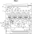
- Fig. 1 is a schematic cross-sectional view of an image forming apparatus 1 according to a first exemplary embodiment.
- the image forming apparatus 1 according to the present exemplary embodiment is a tandem-type multifunction peripheral (including functions of a copier, a printer, and a facsimile apparatus) that employs an intermediate transfer system and can form a full-color image using an electrophotographic system.
- the image forming apparatus 1 includes an apparatus main body 10, a reading device 80, a feeding unit 90, an image formation unit 40, a discharge unit 48, a control unit 30, and an operation unit 70.
- a temperature sensor 71 ( Fig. 2 ) that can detect an internal temperature
- a humidity sensor 72 ( Fig. 2 ) that can detect an internal humidity are provided inside the apparatus main body 10.
- the image forming apparatus 1 can form a full-color (four-color) image onto a recording material (sheet, transfer material, or recording medium) S in accordance with image information (image signal) from the reading device 80 or an external device (external apparatus) 200 ( Fig. 2 ).
- Examples of the external device 200 include a host device such as a personal computer, a digital camera, and a smartphone.
- the recording material S is a recording material onto which a toner image is to be formed. Specific examples include plain paper, a synthetic resin sheet to be substituted for plain paper, thick paper, and an overhead projector sheet.
- the image formation unit 40 can form an image onto the recording material S fed from the feeding unit (feeding device) 90, based on image information.
- the image formation unit 40 includes image forming units 50y, 50m, 50c, and 50k, toner bottles 41y, 41m, 41c, and 41k, exposure devices 42y, 42m, 42c, and 42k, an intermediate transfer unit 44, a secondary transfer device 45, and a fixing unit 46.
- the image forming units 50y, 50m, 50c, and 50k respectively form yellow (Y), magenta (M), cyan (C), and black (K) images.
- the image forming apparatus 1 can also form a monochrome image such as a black image, or a multicolored image using a desired single image forming unit 50 or several image forming units 50.
- the image forming unit 50 includes the following components. First of all, the image forming unit 50 includes a photosensitive drum 51 being a drum-shaped (cylindrical) photosensitive member (electrophotographic photosensitive member) serving as an image bearing member. The image forming unit 50 further includes a charging roller 52 being a roller-shaped charging member serving as a charging unit. The image forming unit 50 further includes a development device 20 serving as a development unit. The image forming unit 50 further includes a preexposure device 54 serving as a charge removal unit. The image forming unit 50 further includes a drum cleaning device 55 serving as a photosensitive member cleaning unit. The image forming unit 50 forms a toner image onto an intermediate transfer belt 44b to be described below. The image forming units 50 are integrally formed as a process cartridge, and detachably attached to the apparatus main body 10.
- the image forming units 50 are integrally formed as a process cartridge, and detachably attached to the apparatus main body 10.
- the photosensitive drum 51 can move (rotate) while bearing an electrostatic image (electrostatic latent image) or a toner image.
- the photosensitive drum 51 is a negatively-charged organic photo conductor (OPC) having an outer diameter of 30 mm.
- OPC organic photo conductor
- the photosensitive drum 51 includes an aluminum cylinder serving as a base member, and surface layers formed on the surface of the aluminum cylinder.
- the photosensitive drum 51 includes three layers as the surface layers. The three layers include an undercoat layer, a photocharge generation layer, and a charge transport layer that are applied and stacked in this order on the base member.
- the photosensitive drum 51 is rotationally driven by a motor (not illustrated) serving as a drive unit, in a direction (counterclockwise direction) indicated by an arrow in Fig. 1 , at a predetermined process speed (circumferential speed).
- the surface of the rotating photosensitive drum 51 is uniformly charged by the charging roller 52 to a predetermined potential of a predetermined polarity (negative polarity in the present exemplary embodiment).
- the charging roller 52 is a rubber roller that contacts the surface of the photosensitive drum 51 and that is driven to rotate in accordance with the rotation of the photosensitive drum 51.
- a charging power source 73 ( Fig. 2 ) is connected to the charging roller 52.
- the charging power source 73 applies a predetermined charging voltage (charging bias) to the charging roller 52 in a charging process.
- the charged surface of the photosensitive drum 51 is subjected to scanning exposure performed by the exposure device 42 based on image information, and an electrostatic image is formed on the photosensitive drum 51.
- the exposure device 42 is a laser scanner.
- the exposure device 42 emits laser light in accordance with image information of decomposition color output from the control unit 30, and performs scanning exposure of the surface (outer circumferential surface) of the photosensitive drum 51.
- the electrostatic image formed on the photosensitive drum 51 is developed (visualized) by being supplied with toner by the development device 20, and a toner image is formed on the photosensitive drum 51.
- the development device 20 stores two-component developer containing nonmagnetic toner particles (toner) and magnetic carrier particles (carrier) as developer. Toner is supplied to the development device 20 from the toner bottle 41.
- the development device 20 includes a development sleeve 24.
- the development sleeve 24 is formed of a nonmagnetic material such as aluminum or nonmagnetic stainless (aluminum in the present exemplary embodiment).
- a magnet roller being a roller-shaped magnet is arranged inside the development sleeve 24 with being fixed in such a manner as not to rotate with respect to the main body (development container) of the development device 20.
- the development sleeve 24 bears developer and conveys the developer to a development region facing the photosensitive drum 51.
- a development power source 74 ( Fig. 2 ) is connected to the development sleeve 24.
- the development power source 74 applies a predetermined development voltage (development bias) to the development sleeve 24 in a development process.
- toner charged to a polarity same (negative polarity in the present exemplary embodiment) as a charging polarity of the photosensitive drum 51 adheres to an exposed portion (image portion) on the photosensitive drum 51 of which an absolute value of a potential declines by being exposed after being uniformly charged (reverse development).
- a regular charging polarity of toner being a charging polarity of toner in development is a negative polarity.
- the intermediate transfer unit 44 is arranged to face the four photosensitive drums 51y, 51m, 51c, and 51k.
- the intermediate transfer unit 44 includes the intermediate transfer belt 44b being an endless belt serving as an intermediate transfer member.
- the intermediate transfer belt 44b is stretched with predetermined tension by being winded around a drive roller 44a, a driven roller 44d, and a secondary transfer inner roller 45a that serve as a plurality of tension rollers (support rollers).
- the intermediate transfer belt 44b can move (rotate) while bearing a toner image.
- the drive roller 44a is rotationally driven by a motor (not illustrated) serving as a drive unit.
- the driven roller 44d is a tension roller that controls the tension of the intermediate transfer belt 44b to be constant.
- the driven roller 44d adds force for pushing the intermediate transfer belt 44b from the inner circumferential side to the outer circumferential side by an urging force of a tension spring (not illustrated) being a urging member serving as an urging unit.
- tension spring (not illustrated) being a urging member serving as an urging unit.
- tension of about 2 to 5kg is applied in a conveyance direction of the intermediate transfer belt 44b.
- the secondary transfer inner roller 45a constitutes the secondary transfer device 45 as described below.
- primary transfer rollers 47y, 47m, 47c, and 47k each being a roller-shaped primary transfer member serving as a primary transfer unit are arranged to face the respective photosensitive drums 51y, 51m, 51c, and 51k.
- the primary transfer roller 47 nips the intermediate transfer belt 44b with the photosensitive drum 51.
- the primary transfer roller 47 thereby contacts the photosensitive drum 51 via the intermediate transfer belt 44b, and a primary transfer portion (primary transfer nip) N1 at which the photosensitive drum 51 and the intermediate transfer belt 44b contact is formed.
- the toner image formed on the photosensitive drum 51 is primarily transferred onto the rotating intermediate transfer belt 44b at the primary transfer portion N1.
- a primary transfer power source 75 ( Fig. 2 ) is connected to the primary transfer roller 47.
- the primary transfer power source 75 applies a primary transfer voltage (primary transfer bias) being a direct-current voltage with a reverse polarity (positive polarity in the present exemplary embodiment) to a regular charging polarity of toner, to the primary transfer roller 47 in a primary transfer process.
- a primary transfer voltage primary transfer bias
- yellow, magenta, cyan, and black toner images formed on the respective photosensitive drums 51y, 51m, 51c, and 51k are sequentially primarily transferred onto the intermediate transfer belt 44b in an overlapped manner.
- a voltage detection sensor 75a that detects an output voltage, and a current detection sensor 75b that detects an output current are connected to the primary transfer power source 75 ( Fig. 2 ).
- the primary transfer power sources 75y, 75m, 75c, and 75k are provided for the respective primary transfer rollers 47y, 47m, 47c, and 47k, and primary transfer voltages to be applied to the primary transfer rollers 47y, 47m, 47c, and 47k can be individually controlled.
- the primary transfer roller 47 includes an elastic layer made of ionic conductive foamed rubber (nitrile rubber(NBR)), and a metal core.
- An outer diameter of the primary transfer roller 47 is 15 to 20 mm, for example.
- a roller having an electric resistance value of 1 ⁇ 10 5 to 1 ⁇ 10 8 ⁇ (measured in N/N (23°C, 50%RH), 2 kV applied) can be desirably used.
- the intermediate transfer belt 44b is an endless belt having a three-layered structure including a base layer, an elastic layer, and a surface layer in this order from the inner circumferential side to the outer circumferential side.
- the material of the base layer a material obtained by mixing an appropriate amount of carbon black as antistat into resin such as polyimide or polycarbonate, or various types of rubber can be desirably used.
- the thickness of the base layer is 0.05 to 0.15 mm, for example.
- an elastic material of the elastic layer a material obtained by mixing an appropriate amount of an ionic conductor into various types of rubber such as urethane rubber or silicone rubber can be desirably used.
- the thickness of the elastic layer is 0.1 to 0.500 mm, for example.
- resin such as fluorine resin can be desirably used.
- the surface layer reduces toner adherence onto the surface of the intermediate transfer belt 44b, and causes toner to be easily transferred onto the recording material S at a secondary transfer portion N2 to be described below.
- the thickness of the surface layer is 0.0002 to 0.020 mm, for example.
- the surface layer uses, as a base material, a resin material of one type such as polyurethane, polyester, or epoxy resin, or materials of two or more types among elastic materials such as elastic rubber, elastomer, and butyl rubber.
- the surface layer is formed by dispersing one type or two or more types of powder or particles of fluorine resin and the like, or the particles with varied particle dimeters, for example, in the base material as a material for reducing surface energy and increasing lubricity.
- the intermediate transfer belt 44b has a volume resistivity of 5 ⁇ 10 8 to 1 ⁇ 10 14 ⁇ cm (23°C, 50%RH), and a hardness of 60 to 85° (23°C, 50%RH) measured by MD1.
- a static friction coefficient of the intermediate transfer belt 44b is 0.15 to 0.6 (23°C, 50%RH, measured by type94i manufactured by HEIDON).
- the intermediate transfer belt 44b has a three-layered structure.
- the intermediate transfer belt 44b may have a single-layered structure including a material equivalent to the above-described material of the base layer, for example.
- a secondary transfer outer roller 45b being a roller-shaped secondary transfer member serving as a secondary transfer unit that constitutes the secondary transfer device 45 together with the secondary transfer inner roller 45a is arranged.
- the secondary transfer outer roller 45b nips the intermediate transfer belt 44b with the secondary transfer inner roller 45a.
- the secondary transfer outer roller 45b thereby contacts the secondary transfer inner roller 45a via the intermediate transfer belt 44b, and the secondary transfer portion (secondary transfer nip) N2 at which the intermediate transfer belt 44b and the secondary transfer outer roller 45b contact is formed.
- a toner image formed on the intermediate transfer belt 44b is secondarily transferred onto the recording material S conveyed with being nipped by the intermediate transfer belt 44b and the secondary transfer outer roller 45b.
- a secondary transfer voltage (secondary transfer bias) is applied to the secondary transfer outer roller 45b in a secondary transfer process.
- the secondary transfer device 45 includes the secondary transfer inner roller 45a serving as a counter member, and the secondary transfer outer roller 45b serving as a secondary transfer member.
- the secondary transfer inner roller 45a is arranged to face the secondary transfer outer roller 45b via the intermediate transfer belt 44b.
- a secondary transfer power source 76 ( Fig. 2 ) serving as a voltage application unit (application unit) is connected to the secondary transfer outer roller 45b.
- the secondary transfer power source 76 applies a secondary transfer voltage (secondary transfer bias) being a direct-current voltage with a reverse polarity (positive polarity in the present exemplary embodiment) to a regular charging polarity of toner, to the secondary transfer outer roller 45b in a secondary transfer process.
- a voltage detection sensor 76a that detects an output voltage, and a current detection sensor 76b that detects an output current are connected to the secondary transfer power source 76 ( Fig. 2 ).
- the metal core of the secondary transfer inner roller 45a is connected to a ground potential.
- the secondary transfer inner roller 45a is electrically grounded (connected to a ground). Then, when the recording material S is supplied to the secondary transfer portion N2, a secondary transfer voltage that is under constant voltage control and has a reverse polarity to a regular charging polarity of toner is applied to the secondary transfer outer roller 45b.
- a secondary transfer voltage of 1 to 7 kV is applied, and a current of 40 to 120 ⁇ A flows, so that a toner image on the intermediate transfer belt 44b is secondarily transferred onto the recording material S.
- a secondary transfer voltage is applied to the secondary transfer portion N2
- the present disclosure is not limited to this configuration.
- a secondary transfer voltage may be applied to the secondary transfer portion N2.
- the secondary transfer outer roller 45b includes an elastic layer made of ionic conductive foamed rubber (NBR), and a metal core.
- An outer diameter of the secondary transfer outer roller 45b is 20 to 25 mm, for example.
- a roller having an electric resistance value of 1 ⁇ 10 5 to 1 ⁇ 10 8 ⁇ (measured in N/N (23°C, 50%RH), 2 kV applied) can be desirably used.
- the recording material S is fed from the feeding unit 90. More specifically, the recording materials S are stacked and stored in a recording material cassette 91 serving as a recording material storage unit.
- the recording material S stored in the recording material cassette 91 is fed to a conveyance path 93 by a feed roller 92 serving as a feeding member.
- the recording material S fed to the conveyance path 93 is conveyed to a registration roller pair 43 serving as a conveyance member, by a conveyance roller pair 94 serving as a conveyance member.
- the skew of the recording material S is corrected by the registration roller pair 43, and the recording material S is supplied to the secondary transfer portion N2 in synchronization with a toner image on the intermediate transfer belt 44b.
- the feeding unit 90 includes the recording material cassette 91, the feed roller 92, the conveyance path 93, and the conveyance roller pair 94.
- the recording material S on which the toner image is transferred is conveyed to the fixing unit (fixing device) 46.
- the fixing unit 46 includes a fixing roller 46a and a pressure roller 46b.
- the fixing roller 46a includes a built-in heater serving as a heating unit.
- the recording material S bearing an unfixed toner image is conveyed with being nipped between the fixing roller 46a and the pressure roller 46b. Heat and pressure are thereby applied to the recording material S.
- the toner image is accordingly fixed (melt, bonded) onto the recording material S.
- a temperature (fixing temperature) of the fixing roller 46a is detected by a fixing temperature sensor 77 ( Fig. 2 ).
- the recording material S onto which the toner image is fixed is conveyed on a discharge path 48a by a discharge roller pair 48b serving as a conveyance member, discharged (output) from a discharge port 48c, and stacked on a discharge tray 48d provided on the outside of the apparatus main body 10.
- the discharge unit (discharge device) 48 includes the discharge path 48a, the discharge roller pair 48b, the discharge port 48c, and the discharge tray 48d.
- the image forming apparatus 1 can execute two-sided image formation (two-sided print, automatic two-sided printing) of forming images on both surfaces of the recording material S.
- a reversing conveyance path 12 for reversing the recording material S having the first surface on which a toner image has been fixed, and supplying the recording material S again to the secondary transfer portion N2 is provided between the fixing unit 46 and the discharge port 48c.
- the recording material S having the first surface on which a toner image has been fixed is guided to the reversing conveyance path 12.
- the conveyance direction of the recording material S is reversed by a switchback roller pair 13 provided on the reversing conveyance path 12, and the recording material S is guided to a two-sided conveyance path 14.
- a two-sided conveyance unit (two-sided conveyance device) 11 includes the reversing conveyance path 12, the switchback roller pair 13, the two-sided conveyance path 14, and the re-conveyance roller pair 15. By the operation of the two-sided conveyance unit 11, images can be formed on both surfaces of one recording material S.
- the charge on the surface of the photosensitive drum 51 having been subjected to primary transfer is removed by the preexposure device 54.
- An adherent such as toner (primary transfer residual toner) remaining on the photosensitive drum 51 without being transferred onto the intermediate transfer belt 44b in the primary transfer process is removed from the surface of the photosensitive drum 51 and collected by the drum cleaning device 55.
- the drum cleaning device 55 scrapes off the adherent from the surface of the rotating photosensitive drum 51 using a cleaning blade serving as a cleaning member that contacts the surface of the photosensitive drum 51, and stores the adherent into a cleaning container.
- the cleaning blade is brought into contact with the surface of the photosensitive drum 51 by predetermined pressing force in such a manner that its leading end on a free end side is oriented in a counter direction for facing an upstream side in the rotation direction of the photosensitive drum 51.
- the intermediate transfer unit 44 includes a belt cleaning device 60 serving as an intermediate transfer member cleaning unit. An adherent such as toner (secondary transfer residual toner) remaining on the intermediate transfer belt 44b without being transferred onto the recording material S in the secondary transfer process is removed from the surface of the intermediate transfer belt 44b and collected by the belt cleaning device 60.
- the reading device 80 serving as a reading unit (reading unit) is arranged in an upper part of the apparatus main body 10.
- the reading device 80 includes an automatic document conveyance device (automatic document feeder (ADF)) 81 serving as a document conveyance unit (document conveyance unit), a platen glass 82, an optical system 84 including a light source 83, mirrors 84a, and an image forming lens 84b, and a reading element 85 such as a charge-coupled device (CCD) image sensor.
- ADF automatic document feeder
- CCD charge-coupled device
- the reading device 80 can sequentially read images on a document (the recording material S on which images are formed) arranged on the platen glass 82, by the reading element 85 via the optical system 84 while performing scanning exposure using the movable light source 83.
- the reading device 80 sequentially illuminates documents arranged on the platen glass 82, with light from the moving light source 83, and sequentially forms optical images onto the reading element 85 via the optical system 84 based on reflected light from the documents.
- the reading element 85 can thereby read the images on the documents at a predefined dot density.
- the platen glass 82 forms a reading surface supporting the recording material S in such a manner that the reading device 80 can read the recording material S.
- the reading device 80 can sequentially read images on documents conveyed by the automatic document conveyance device 81, by the reading element 85 via the optical system 84 by sequentially exposing the documents using the light source 83 in accordance with the conveyance of the documents.
- the reading device 80 sequentially illuminates documents passing through a predetermined reading position on the platen glass 82, with light from the light source 83, and sequentially forms optical images onto the reading element 85 via the optical system 84 based on reflected light from the documents.
- the reading element 85 can thereby read the images on the documents at a predefined dot density.
- the automatic document conveyance device 81 automatically conveys documents one by one in a separated state in such a manner as to cause the documents to pass through the above-described reading position of the reading device 80.
- the automatic document conveyance device 81 forms a conveyance device that sequentially conveys the recording materials S in such a manner that the reading device 80 can read the recording materials S.
- the reading device 80 optically reads an image on the recording material S placed on the platen glass 82 or conveyed by the automatic document conveyance device 81, and converts the read image into an electric signal.
- the reading device 80 can arrange, on the platen glass 82, one recording material S having a large size such as an A3 size, or two recording materials S having a small size such as an A4 size, side by side.
- the reading device 80 can continuously convey a plurality of recording materials S having an A3 size or an A4 size, for example, that is stacked on a document stacking portion of the automatic document conveyance device 81, to the above-described reading position.
- the automatic document conveyance device 81 can automatically read images on both surfaces of the recording material S.
- an image on a document read by the reading device 80 is transmitted to an image processing unit of the control unit 30 as three-color image data corresponding to red (R), green (G), blue (B) (8 bits for each color), for example.
- predetermined image processing is executed as necessary on the image data of the document, and the image data is converted into image data of four colors including yellow, magenta, cyan, and black. Examples of the above-described image processing include shading correction, positional shift correction, brightness/color space conversion, gamma correction, frame deletion, and color/moving edition.
- Image data corresponding to four colors including yellow, magenta, cyan, and black are sequentially transmitted to the respective exposure devices 42y, 42m, 42c, and 42k, and the above-described image exposure is performed in accordance with the image data.
- the reading device 80 is also used for reading patches on a chart (acquiring density information (luminance information)) in an adjustment mode as described in detail below.
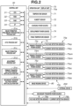
- Fig. 2 is a block diagram schematically illustrating a configuration of a control system of the image forming apparatus 1 according to the present exemplary embodiment.
- the control unit 30 is formed by a computer.
- the control unit 30 includes, for example, a central processing unit (CPU) 31 serving as a calculation control unit, a read-only memory (ROM) 32 serving as a storage unit and storing a program for controlling each component, a random access memory (RAM) 33 serving as a storage unit and temporarily storing data, and an input-output circuit (interface (I/F)) 34 that inputs and outputs a signal from and to the outside.
- CPU central processing unit
- ROM read-only memory
- RAM random access memory
- I/F input-output circuit
- the CPU 31 is a microprocessor that governs the entire control of the image forming apparatus 1, and predominantly constitutes a system controller. Via the input-output circuit 34, the CPU 31 is connected to the feeding unit 90, the image formation unit 40, the discharge unit 48, and the operation unit 70, and exchanges signals with these components and controls operations of these components.
- the ROM 32 stores an image formation control sequence for forming an image onto the recording material S.
- the charging power source 73, the development power source 74, the primary transfer power source 75, and the secondary transfer power source 76 are connected to the control unit 30, and these components are controlled in accordance with signals from the control unit 30.
- the temperature sensor 71, the humidity sensor 72, the voltage detection sensor 75a and the current detection sensor 75b of the primary transfer power source 75, the voltage detection sensor 76a and the current detection sensor 76b of the secondary transfer power source 76, and the fixing temperature sensor 77 are also connected to the control unit 30. A signal detected by each sensor is input to the control unit 30.
- the operation unit 70 includes an input unit such as an operation button that serves as an input unit, and a display unit 70a including a liquid crystal panel that serves as a display unit.
- the display unit 70a is formed as a touch panel, and also has a function as an input unit.
- an operator such as a user or a service staff can execute a job (to be described below).
- the control unit 30 operates various devices of the image forming apparatus 1 upon receiving signals from the operation unit 70.
- the image forming apparatus 1 can also execute a job based on an image formation signal (image data, control command) from the external device 200 such as a personal computer.
- the control unit 30 includes an image formation preliminary preparation process unit 31a, an active transfer voltage control (ATVC) process unit 31b, an image formation process unit 31c, and an adjustment process unit 31d.
- the control unit 30 further includes a primary transfer voltage storage unit/calculation unit 31e and a secondary transfer voltage storage unit/calculation unit 31f. These process units and the storage units/calculation units may be provided as a part of the CPU 31 or the RAM 33.
- the control unit 30 (more specifically, the image formation process unit 31c) can execute a job as described above.
- the control unit 30 (more specifically, the ATVC process unit 31b) can execute ATVC (setting mode) of a primary transfer portion and a secondary transfer portion.
- the ATVC will be described in detail below.
- the control unit 30 (more specifically, the adjustment process unit 31d) can execute an adjustment mode for adjusting a set voltage of a secondary transfer voltage. The adjustment mode will be described in detail below.
- the image forming apparatus 1 executes a job (image output operation, print job) being a series of operations of forming images onto one or a plurality of recording materials S and outputting the recording materials S that is started in accordance with one start instruction.
- a job generally includes an image forming process, a preliminary rotation process, a sheet-to-sheet interval process in the case of forming images onto a plurality of recording materials S, and a post rotation process.
- the image forming process corresponds to a period for forming an electrostatic image forming a toner image, and performing primary transfer and secondary transfer of the toner image, of an image to actually be output by being formed on the recording material S.
- An image forming state (image forming period) refers to this period.
- the timing of the image forming state varies depending on the positions at which these processes including the formation of an electrostatic image, the formation of a toner image, and the primary transfer and secondary transfer of the toner image are performed.
- the preliminary rotation process corresponds to a period for performing a preparation operation prior to the image forming process, and corresponds to a period from the input of a start instruction until an image actually starts to be formed.
- the sheet-to-sheet interval process corresponds to a period corresponding to an interval between the recording material S and the recording material S in continuously performing image formation onto a plurality of recording materials S (continuous image formation).
- the post rotation process corresponds to a period for performing an arrangement operation (preparation operation) subsequent to the image forming process.
- a non-image forming state corresponds to a period other than the image forming state, and includes the above-described preliminary rotation process, the sheet-to-sheet interval process, and the post rotation process.
- the non-image forming state further includes a preliminary multiple rotation process being a preparation operation to be performed when the power of the image forming apparatus 1 is turned on or when the image forming apparatus 1 recovers from a sleep state.
- FIG. 3 is flowchart schematically illustrating a procedure of control of a secondary transfer voltage according to the present exemplary embodiment.
- the control of a secondary transfer voltage generally includes constant voltage control and constant current control. In the present exemplary embodiment, constant voltage control is used.
- the control unit 30 (the image formation preliminary preparation process unit 31a) starts an operation of a job upon acquiring job information from the operation unit 70 or the external device 200.
- the job information includes image information designated by an operator, and information regarding the recording material S.
- the information regarding the recording material S may include a size (width, length) of the recording material S on which an image is to be formed, information (thickness, grammage, etc.) related to the thickness of the recording material S, and information related to a surface property of the recording material S such as information indicating whether the recording material S is coated paper.
- the information regarding the recording material S includes information regarding the size of the recording material S, and information regarding a category (so-called paper type category) of the recording material S such as "thin paper, plain paper, thick paper, and so on" that is related to the thickness of the recording material S.
- a category so-called paper type category
- the information regarding the recording material S encompasses arbitrary information that can identify the recording material S, such as an attribute (so-called paper type category) that is based on general features, including plain paper, high-quality paper, glazed paper, gloss paper, coated paper, embossed paper, thick paper, and thin paper, a numerical value or a numerical value range of grammage, thickness, size, and rigidity, or brand (including a manufacturer, product name, product number).
- the recording materials S can be classified by a type identified based on the information regarding the recording material S.
- the information regarding the recording material S may be included in information regarding a print mode designating an operation setting of the image forming apparatus 1, such as "plain paper mode” and "thick paper mode", or may be substituted by information regarding a print mode.
- the control unit 30 writes the job information into the RAM 33.
- step S103 the control unit 30 acquires environment information detected by the temperature sensor 71 and the humidity sensor 72.
- the ROM 32 stores information indicating a correlative relationship between environment information and a target current Itarget for transferring a toner image on the intermediate transfer belt 44b onto the recording material S.
- the control unit 30 (the secondary transfer voltage storage unit/calculation unit 31f) obtains a target current Itarget suitable for the environment from the above-described information indicating a relationship between the environment information and the target current Itarget.
- step S104 the control unit 30 writes the target current Itarget into the RAM 33 (or the secondary transfer voltage storage unit/calculation unit 31f).
- the target current Itarget is changed in accordance with the environment information because a charge amount of toner varies depending on the environment.
- the above-described information indicating a relationship between the environment information and the target current Itarget is information preliminarily obtained by an experiment.
- step S105 the control unit 30 (the ATVC process unit 31b) acquires information regarding an electric resistance of the secondary transfer portion N2 by ATVC before a toner image on the intermediate transfer belt 44b, and the recording material S onto which a toner image is to be transferred reach the secondary transfer portion N2.
- predetermined voltages at plurality of levels are supplied from the secondary transfer power source 76 to the secondary transfer outer roller 45b.
- the current detection sensor 76b detecting current values obtained when the predetermined voltages are supplied, a relationship between voltage and current (voltage and current characteristics) as illustrated in Fig. 4 is acquired.
- the control unit 30 writes the information indicating a relationship between voltage and current, into the RAM 33 (or the secondary transfer voltage storage unit/calculation unit 31f).
- the relationship between voltage and current changes in accordance with an electric resistance of the secondary transfer portion N2.
- current changes as represented by a second-order or higher-order polynomial expression (quadratic expression in the present exemplary embodiment) of voltage without changing linearly with respect to (being proportional to) voltage.
- step S106 the control unit 30 (the secondary transfer voltage storage unit/calculation unit 31f) obtains a value of a voltage to be applied to the secondary transfer outer roller 45b from the secondary transfer power source 76.
- the control unit 30 obtains a value of a voltage Vb necessary for flowing the target current Itarget in a state in which the recording material S does not exist at the secondary transfer portion N2.
- the voltage Vb corresponds to a secondary transfer portion divided voltage (transfer voltage corresponding to an electric resistance of the secondary transfer portion N2). As illustrated in Fig.
- the ROM 32 stores information for obtaining a recording material divided voltage (transfer voltage corresponding to an electric resistance of the recording material S) Vp.
- the information is set as table data indicating a relationship between a water amount of atmosphere and the recording material divided voltage Vp for each group of grammages of the recording material S (corresponding to paper type category).
- the control unit 30 can obtain a water amount of atmosphere based on the environment information (temperature and humidity) detected by the temperature sensor 71 and the humidity sensor 72.
- the control unit 30 (the secondary transfer voltage storage unit/calculation unit 31f) obtains the recording material divided voltage Vp from the above-described table data based on the job information acquired in step S101, and the environment information acquired in step S103.
- the control unit 30 obtains an adjustment amount ⁇ V in accordance with the adjustment value.
- the adjustment amount ⁇ V is stored in the RAM 33 (or the secondary transfer voltage storage unit/calculation unit 31f).
- the table data for obtaining the recording material divided voltage Vp that is illustrated in Fig. 5 is data preliminarily obtained by an experiment.
- the recording material divided voltage Vp also changes in accordance with the surface property of the recording material S aside from information (thickness, grammage, etc.) related to the thickness of the recording material S.
- the above-described table data may be set in such a manner that the recording material divided voltage Vp also changes in accordance with information related to the surface property of the recording material S.
- information related to the thickness of the recording material S is included in the job information acquired in step S101.
- the image forming apparatus 1 may be provided with a measurement unit that detects a thickness of the recording material S or a surface property of the recording material S, and the recording material divided voltage Vp may be obtained based on information obtained by the measurement unit.
- step S107 the control unit 30 (the image formation process unit 31c) causes image formation to be executed, and causes secondary transfer to be performed by feeding the recording material S to the secondary transfer portion N2 and applying the secondary transfer voltage Vtr determined as described above.
- step S108 the control unit 30 (the image formation process unit 31c) repeats the processing in step S107 until all the images of the job are transferred onto the recording material S and the output ends.
- ATVC similar to the above-described control is performed on the primary transfer portion N1 during a period from the start of the job until a toner image is conveyed to the primary transfer portion N1, but the detailed description will be omitted.
- a water amount or an electric resistance value of the recording material S sometimes differ significantly from that of a standard recording material S.
- optimum transfer sometimes fails to be performed by a set voltage of a secondary transfer voltage that is set using a preset default recording material divided voltage Vp as described above.
- the secondary transfer voltage is to be initially set to a voltage required for transferring toner on the intermediate transfer belt 44b onto the recording material S.
- the secondary transfer voltage is to be suppressed to a voltage at which abnormal electric discharge does not occur.
- an electric resistance is sometimes higher than a value expected as a standard value.
- a set voltage of a secondary transfer voltage that is set using the preset default recording material divided voltage Vp sometimes becomes insufficient as a voltage required for transferring toner on the intermediate transfer belt 44b onto the recording material S.
- an electric resistance is sometimes lower than a value expected as a standard value due to an increased water amount of the recording material S, and electric discharge sometimes easily occurs.
- a set voltage of a secondary transfer voltage that is set using the preset default recording material divided voltage Vp sometimes causes an image defect due to abnormal electric discharge.
- an operator such as a user or a service staff is sometimes demanded to adjust (change) a set voltage of a secondary transfer voltage in job execution to an optimum value by adjusting (changing) the recording material divided voltage Vp in accordance with the recording material S to be actually used in image formation.
- the recording material divided voltage Vp in accordance with the recording material S to be actually used in image formation.
- it is sometimes demanded to select an optimum recording material divided voltage Vp + ⁇ V (adjustment amount) suitable for the recording material S to be actually used in image formation.
- the adjustment is also considered to be performed by the following method.
- the method is a method of determining a set voltage of an optimum secondary transfer voltage (more specifically, the recording material divided voltage Vp + ⁇ V) by an operator outputting images desired to be output, while switching a secondary transfer voltage for one recording material S, and checking the output images. Nevertheless, in this method, because image output and adjustment of a set voltage of a secondary transfer voltage are repeated, in some cases, the number of wasted recording materials S increases, and the adjustment takes time.
- the image forming apparatus 1 includes an adjustment mode for adjusting a set voltage of a secondary transfer voltage.
- the image forming apparatus 1 outputs a chart including a plurality of patches (test images) in representative colors that is formed on the recording material S to be actually used in image formation, while switching a set voltage of a secondary transfer voltage for each patch. Then, based on a reading result of the output chart that is obtained by the reading device 80, a set voltage of an optimum secondary transfer voltage (more specifically, the recording material divided voltage Vp + ⁇ V) can be determined.
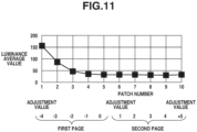
- a recommended adjustment amount ⁇ V of a set voltage of a secondary transfer voltage is presented based on density information (luminance information) of a patch (typically, solid image patch) on the chart.
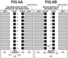
- Figs. 6A and 6B , and Figs. 7A, 7B, 7C, and 7D are schematic diagrams of a chart 100 according to the present exemplary embodiment.
- charts are broadly divided into two types of charts 100 illustrated in Figs. 6A and 6B , and Figs. 7A, 7B, 7C, and 7D , and in the adjustment mode, the two types of charts 100 are output in accordance with the size of the recording material S to be used.
- Figs. 6A and 6B illustrate the chart 100 to be output in a case where a length in the conveyance direction of the recording material S is 420 to 487 mm.
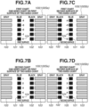
- Figs. 7A, 7B, 7C, and 7D illustrate the chart 100 to be output in a case where a length in the conveyance direction of the recording material S is 210 to 419 mm.
- charts can be output onto both surfaces of the recording material S also in the adjustment mode in such a manner that secondary transfer voltages to be applied in secondary transfer onto the front surface (the first surface) and the rear surface (the second surface) in two-sided image formation can be individually adjusted.
- Figs. 6A and 6B , and Figs. 7A, 7B, 7C, and 7D illustrate a chart (hereinafter, will also be referred to as a "one-sided chart”) to be formed on one surface of the recording material S, and a chart (hereinafter, will also be referred to as a "two-sided chart”) to be formed on both surfaces of the recording material S.
- the two-sided chart is formed by two-sided image formation using the above-described two-sided conveyance unit 11.
- the size of the recording material S is indicated by a recording material width (main scanning direction length) ⁇ a recording material length (sub scanning direction length).
- the recording material width is a length in a direction (width direction) substantially orthogonal to the conveyance direction of the recording material S in passing through the secondary transfer portion N2.
- the recording material length is a length in a direction substantially parallel to the conveyance direction of the recording material S in passing through the secondary transfer portion N2.
- Figs. 6A and 6B illustrate charts (hereinafter, will also be referred to as "large charts") 100L (100La and 100Lb) for large-sized recording materials that are to be output in a case where the recording material S having a large size such as an A3 size (297 mm ⁇ 420 mm) or Ledger (about 280 mm ⁇ 432 mm) is used.
- Fig. 6A illustrates the large chart 100La output as a one-sided chart, or output as the first surface of a two-sided chart.
- Fig. 6B illustrates the large chart 100Lb output as the second surface of a two-sided chart.
- Figs. 7A, 7B, 7C, and 7D illustrate charts (hereinafter, will also be referred to as "small charts") 100S (100Sa and 100Sb) for small-sized recording materials that are to be output in a case where the recording material S having a small size such as A4 landscape (297 mm ⁇ 210 mm) or letter landscape (about 280 mm ⁇ 216 mm) is used.
- Figs. 7A and 7B respectively illustrate the small chart 100Sa output as the first one-sided chart or the first surface of the first two-sided chart, and the small chart 100Sa output as the second one-sided chart or the first surface of the second two-sided chart.
- Figs. 7C and 7D respectively illustrate the small chart 100Sb output as the second surface of the first two-sided chart, and the small chart 100Sb output as the second surface of the second two-sided chart.
- a square shape can be employed as the shape of patches.
- the colors of patches can be determined depending on an image defect desired to be checked and the easiness of check. For example, in a case where a secondary transfer voltage is increased from a low value, a lower limit value of a secondary transfer voltage can be determined based on a voltage value at which patches in secondary colors such as red, green, and blue can be appropriately transferred.
- an upper limit value of a secondary transfer voltage can be determined based on a voltage value at which an image defect occurs in halftone patches due to a high secondary transfer voltage.
- the chart 100 includes patch sets each including one blue sold patch 101, one black sold patch 102, and two halftone patches 103 arrayed side by side in a width direction.
- eleven patch sets each including the width-direction-arrayed patches 101 to 103 are arrayed in the conveyance direction.
- the large charts 100S in Figs. 7A, 7B, 7C, and 7D ten patch sets each including the width-direction-arrayed patches 101 to 103 are arrayed in the conveyance direction.
- the halftone patches 103 are gray (black halftone) patches. Solid images are images having the highest density level.
- a halftone image is an image with a toner application amount of 10 to 80% when a toner application amount of a solid image is 100%, for example.
- patch identification information 104 for identifying the setting of a secondary transfer voltage applied to each patch set is provided in association with a corresponding set of the patches 101 to 103.
- the patch identification information 104 may be a value corresponding to an adjustment value of a secondary transfer voltage to be described below.
- front/rear identification information 105 indicating at least one of the front surface (the first surface) or the rear surface (the second surface) of the recording material S may be provided on at least one of the front surface (the first surface) or the rear surface (the second surface) of the recording material S.
- the patches desirably have sizes that enable the operator to easily determine the existence or non-existence of an image defect. If the sizes of patches are small, it tends to become difficult to determine the transferability of the blue sold patch 101 and the black sold patch 102.
- the size of patches is desirably set to a size equal to or larger than a size of 10 mm ⁇ 10 mm, and more desirably set to a size equal to or larger than a size of 25 mm ⁇ 25 mm.
- a width in the conveyance direction of the halftone patch 103 is set to a width which is the same as the widths in the conveyance direction of the blue sold patch 101 and the black sold patch 102.
- An interval between patch sets each including patches 101 to 103 that are arrayed in the conveyance direction is only required to be set in such a manner that a secondary transfer voltage can be switched.
- the blue sold patches 101 and the black sold patches 102 are squares (one side is substantially parallel to the width direction) each having a size of 25.7 mm ⁇ 25.7 mm.
- the halftone patches 103 at both ends in the width direction each have a width in the conveyance direction of 25.7 mm, and extend up to the ends of the chart 100 in the width direction.
- an interval in the conveyance direction between patch sets each including the patches 101 to 103 is set to 9.5 mm.
- patch sets each including the patches 101 to 103 that are formed on the chart 100 are sequentially transferred from the upstream side toward the downstream side in the conveyance direction of the recording material S in forming the chart 100, using a plurality of secondary transfer voltages (test voltages) varied to have sequentially increasing absolute values.
- the patch sets each including the patches 101 to 103 that are formed on the chart 100 may be sequentially transferred from the upstream side toward the downstream side in the conveyance direction of the recording material S in forming the chart 100, using a plurality of secondary transfer voltages (test voltages) varied to have sequentially decreasing absolute values.
- no patch is formed near the leading end and the posterior end in the conveyance direction of the recording material S (for example, a range of about 20 to 30 mm inward from the edge end) for the following reason. More specifically, out of the ends in the conveyance direction of the recording material S, an image defect sometimes occurs only at the leading end or the posterior end in the conveyance direction, without occurring at the ends in the width direction. In this case, it sometimes becomes difficult to determine whether an image defect has occurred due to an allocated secondary transfer voltage.
- the largest size of the recording material S that can be used in the image forming apparatus 1 according to the present exemplary embodiment is a size of 13 inches (about 330 mm) ⁇ 19.2 inches (about 487 mm).
- the large charts 100L illustrated in Figs. 6A and 6B correspond to the recording material S having the largest size.
- the size of the recording material S is equal to or smaller than the size of 13 inches ⁇ 19.2 inches, and equal to or larger than the A3 size (297 mm ⁇ 420 mm)
- a chart corresponding to image data extracted from image data of the large chart 100L illustrated in Fig. 6A or 6B in accordance with the size of the recording material S is output.
- image data is extracted in accordance with the size of the recording material S with reference to the leading end center. More specifically, image data is extracted in a state in which the leading end in the conveyance direction of the recording material S and the leading end (upper end in Figs. 6A and 6B ) in the conveyance direction of the large chart 100L are aligned, and the center in the width direction of the recording material S and the center in the width direction of the large chart 100L are aligned. In the present exemplary embodiment, image data is extracted in such a manner that margins of 2.5 mm are provided at the ends (in the present exemplary embodiment, both ends in the width direction and both ends in the conveyance direction).
- the large chart 100L is output onto the recording material S having the A3 size (297 mm ⁇ 420 mm)
- image data corresponding to the range of 292 mm ⁇ 415 mm is extracted while providing a margin of 2.5 mm at each end.
- the large chart 100L corresponding to the image data is output onto the recording material S having the A3 size (297 mm ⁇ 420 mm), with respect to the leading end center.
- the size in the width direction of the halftone patches 103 at the ends in the width direction becomes smaller.
- a margin at a posterior end in the conveyance direction becomes smaller.
- eleven patch sets corresponding to -5 to 0 to +5 are arranged on the large chart 100L.
- the eleven patch sets each including the patches 101 to 103 are arranged within the range with a length in the conveyance direction of 387 mm in such a manner as to fall within a length in the conveyance direction of 415 mm that is set in a case where the size of the recording material S is the A3 size.
- the small charts 100S illustrated in Figs. 7A, 7B, 7C, and 7D are output.
- the small charts 100S illustrated in Figs. 7A, 7B, 7C, and 7D correspond to a size from an A5 size (vertical feed) to a size smaller than the A3 size (297 mm ⁇ 420 mm) (i.e., length of 210 to 419 mm in the conveyance direction).
- ten patch sets in total including five sets corresponding to -4 to 0 on the first chart, and five sets corresponding to +1 to +5 on the second chart are arranged on the small chart 100S.
- the size of image data of the small chart 100S is 13 inches ⁇ 210 mm.
- the size in the width direction is adjusted by reducing the size of the halftone patches 103 in the width direction in accordance with the size of the recording material S.
- the size in the conveyance direction is set in such a manner that five patch sets fall within a length in the conveyance direction of 167 mm, and a margin at the posterior end becomes longer in accordance with the length of 210 to 419 mm in the conveyance direction of the recording material S.
- the blue sold patches 101 and the black sold patches 102 on the front surface (the first surface) and the rear surface (the second surface) of the two-sided chart are arranged in such a manner as not to overlap each other on the front and rear surfaces of the recording material S.
- a patch interval in the width direction is set to 5.4 mm. This is for suppressing a variation in detection result of patch density on the second surface due to the influence of patch density on the first surface, and for more accurately adjusting a secondary transfer voltage on the second surface.
- the chart 100 can be output using a recording material S with an arbitrary size (free size) by the operator designating a size by inputting the size from the operation unit 70 or the external device 200, for example.
- Fig. 8 is a flowchart schematically illustrating a procedure in the adjustment mode according to the present exemplary embodiment.
- Figs. 9A, 9B, and 9C are schematic diagrams illustrating an example of a setting screen of an adjustment mode. The description will be given of an example case where an operator executes the adjustment mode by inputting an instruction from the operation unit 70 of the image forming apparatus 1. The description will be given of an example case where density information (luminance information) of a patch is read in a state in which the recording material S including the formed chart 100 is placed by the operator on the platen glass 82 (original platen glass) of the reading device 80. For the sake of simplicity, a recording material on which a chart is formed will be sometimes simply referred to as a "chart".
- the control unit 30 displays a setting screen 300 of an adjustment mode as illustrated in Fig. 9A , on the display unit 70a of the operation unit 70.
- the setting screen 300 includes a voltage setting unit 301 for setting an adjustment value of a secondary transfer voltage for the front surface (the first surface) and the rear surface (the second surface) of the recording material S.
- the setting screen 300 further includes an output surface selection unit 302 for selecting whether to output the chart 100 onto one surface or both surfaces of the recording material S.
- the setting screen 300 further includes an output instruction unit (chart output button) 303 for issuing an output instruction of the chart 100.
- the setting screen 300 further includes a determination unit (OK button) 304 for determining the setting, and a cancel button 305 for cancelling the change of the setting.
- the setting screen 300 further includes a message display unit 306 for displaying various messages regarding the adjustment mode.
- a start button 307 provided in the operation unit 70 adjacently to the display unit 70a functions as an input unit for inputting a reading start instruction of the chart 100 to the reading device 80.
- a display (button) functioning as the input unit may be provided on the above-described setting screen 300 displayed on the display unit 70a.
- a secondary transfer voltage (more specifically, the recording material divided voltage Vp) is set to a specified value (table value) preset for the currently-selected recording material S.
- the secondary transfer voltage may be set to a value currently-set for the currently-selected recording material S.
- a center voltage value (value corresponding to the patch set of 0 on the chart 100) of secondary transfer voltages in outputting the chart 100 is set to the value.
- the secondary transfer voltage is adjusted by an adjustment amount ⁇ V of 150 V for each level of an adjustment value.
- a center voltage value of secondary transfer voltages in outputting the chart 100 is set to the value.
- the chart output button 303 being operated after an adjustment value is selected, the chart 100 is output with the selected center voltage value.
- the OK button 304 being operated after an adjustment value is selected, the adjustment value of a secondary transfer voltage is determined.
- the control unit 30 acquires information regarding a setting such as a center voltage value that has been input in the operation unit 70 via the setting screen 300, and stores the information into a storage unit (the RAM 33, the secondary transfer voltage storage unit/calculation unit 31f, etc.) as necessary.
- step S201 the control unit 30 displays the setting screen 300 of the adjustment mode on the display unit 70a.
- the control unit 30 displays the setting screen 300 on the display unit 70a.
- the control unit 30 acquires the information regarding the recording material S that has been input by the operator on the input screen, and adjusts a secondary transfer voltage in association with the information regarding the recording material S.
- the information regarding the recording material S may be acquired in the following manner. If the recording material cassette 91 storing the recording material S to be used in the adjustment mode is selected, information preset in association with the recording material cassette 91 may be acquired.
- step S202 the control unit 30 acquires a setting of a center voltage value of secondary transfer voltages in outputting the chart 100, and a setting indicating whether to output a one-sided chart or a two-sided chart, which have been input by the operator on the setting screen 300.
- step S203 the control unit 30 acquires a signal indicating that the operator has operated the chart output button 303 on the setting screen 300.
- step S204 the control unit 30 acquires a second-order or higher-order polynomial expression (quadratic expression in the present exemplary embodiment) of a relationship between voltage and current that corresponds to an electric resistance of the secondary transfer portion N2, by an operation similar to the above-described ATVC, precedential to the output of the chart 100.
- step S205 the control unit 30 sets a secondary transfer voltage (test voltage) based on the acquired information regarding the relationship between voltage and current, and information regarding the center voltage value set on the setting screen 300, and performs control to output the chart 100.
- the control unit 30 performs control to output a predetermined chart 100 suitable for the size of the recording material S, by adjusting image data of the chart 100 as described above, and changing a secondary transfer voltage every 150 V.
- a secondary transfer voltage test voltage
- step S206 the control unit 30 determines whether the reading device 80 can read the chart 100, based on whether the size of the recording material S used for outputting the chart 100 is a size readable by the reading device 80.
- the processing proceeds to step S220.
- the control unit 30 can display a message for prompting the operator to manually adjust a secondary transfer voltage, in the message display unit 306 ( Fig. 9A ) of the setting screen 300 as illustrated in Fig. 9B , for example.
- step S220 In a case where the size of the recording material S used for outputting the chart 100 is a size unreadable by the reading device 80, in step S220, a secondary transfer voltage can be manually adjusted by inputting an adjustment value in the voltage setting unit 301 ( Fig. 9A ) of the setting screen 300.
- the control unit 30 determines in step S206 that reading is executable (YES in step S206)
- the processing proceeds to step S207.
- step S207 the control unit 30 waits for a reading start instruction of the chart 100 to be input by the operator operating the start button 307 in the operation unit 70.
- the control unit 30 can display a message for prompting the operator to set the charts 100 on the reading device 80, in the message display unit 306 ( Fig.
- Fig. 9C illustrates an example case where the small charts 100S are output.
- the control unit 30 can present a candidate of a desirable setting of a secondary transfer voltage based on a reading result of the chart 100 that is obtained by the reading device 80.
- the control unit 30 advances the processing to step S220.
- step S207 if the control unit 30 acquires a reading start signal for issuing a reading start instruction of the chart 100, from the operation unit 70, the processing proceeds to step S208.
- step S208 the control unit 30 determines whether the size of the recording material S used for outputting the chart 100 is a large size. In a case where the control unit 30 determines in step S208 that the size of the recording material S is a large size such as the A3 size (297 mm ⁇ 420 mm) or Ledger (about 280 mm ⁇ 432 mm) (YES in step S208), the processing proceeds to step S209.
- step S209 the control unit 30 determines whether a one-sided chart has been output or a two-sided chart has been output. In a case where the control unit 30 determines in step S209 that a one-sided chart has been output (YES in step S209), the processing proceeds to step S210. In step S210, only one surface of the recording material S is read by the reading device 80. In a case where the control unit 30 determines in step S209 that a two-sided chart has been output (NO in step S209), the processing proceeds to step S211. In step S211, first of all, the front surface (the first surface) of the recording material S is read by the reading device 80.
- step S212 the rear surface (the second surface) of the recording material S is read.
- one large chart 100L on which eleven patch sets corresponding to -5 to 0 to +5 are formed, which has been set on the reading device 80 is read in accordance with one reading start signal.
- step S208 determines in step S208 that the size of the recording material S is a small size such as A4 landscape (297 mm ⁇ 210 mm) or letter landscape (about 280 mm ⁇ 216 mm)
- the processing proceeds to step S213.
- step S213 the control unit 30 determines whether a one-sided chart has been output or a two-sided chart has been output.
- step S214 only one surfaces of two recording materials S are simultaneously read by the reading device 80.
- step S213 In a case where the control unit 30 determines in step S213 that a two-sided chart has been output (NO in step S213), the processing proceeds to step S215.
- step S215 first of all, the front surfaces (the first surfaces) of the two recording materials S are simultaneously read by the reading device 80. After that, if the control unit 30 acquires a reading start signal again from the operation unit 70, in step S216, the rear surfaces (the second surfaces) of the two recording materials S are simultaneously read.
- the first small chart 100S on which five patch sets corresponding to -4 to 0 are formed, and the second small chart 100S on which five patch sets corresponding to +1 to +5 are formed, which have been simultaneously set on the reading device 80 are read in accordance with one reading start signal.
- the above-described one reading start signal is input to the control unit 30 by the operator operating the start button 307 serving as an input unit. Nevertheless, the present disclosure is not limited to this configuration.
- the reading device 80 can include a sensor detecting that a document is arranged on the reading surface, or detecting that a document is placed on the document stacking portion of the automatic document conveyance device 81, and automatically start the reading of the document in accordance with a detection result obtained by the sensor.
- the above-described one reading start signal may be input to the control unit 30 from the above-described sensor serving as an input unit.
- step S217 the control unit 30 determines a reading error for determining whether the chart 100 has failed to be properly read by the reading device 80.
- the description is given of an example case where the chart 100 placed on the platen glass 82 is read.
- a reading error can be determined in a case where any trouble occurs in the conveyance of the chart 100 that is performed by the automatic document conveyance device 81.
- the control unit 30 determines in step S217 that no reading error has been detected (NO in step S217)
- the processing proceeds to step S218.
- step S218 the control unit 30 performs processing of determining an adjustment value of a secondary transfer voltage. The processing of determining an adjustment value of a secondary transfer voltage will be described below.
- the control unit 30 determines in step S217 that a reading error has detected (YES in step S217), the processing returns to step S207, and the control unit 30 determines again whether to use the reading device 80.
- step S219 the control unit 30 displays the adjustment value determined in step S218, in the voltage setting unit 301 of the setting screen 300.
- the adjustment value indicates a candidate of a desirable setting of a secondary transfer voltage.
- the operator can determine whether the adjustment value displayed on the setting screen 300 is suitable. In a case where the operator does not change the adjustment value displayed on the setting screen 300, the operator operates the OK button 304 on the setting screen 300 without making any change.
- the operator in a case where the operator changes (manually adjusts) the adjustment value displayed on the setting screen 300, the operator inputs an adjustment value desired to be set, into the voltage setting unit 301 of the setting screen 300, and operates the OK button 304 on the setting screen 300.
- step S220 the control unit 30 determines whether the adjustment value has been changed. Then, in a case where the control unit 30 acquires a signal indicating that the OK button 304 has been operated without the adjustment value being changed (NO in step S220), the processing proceeds to step S221.
- step S221 the control unit 30 stores the adjustment value determined in step S218, into the RAM 33 (or the secondary transfer voltage storage unit/calculation unit 31f).
- step S222 the control unit 30 stores the adjustment value input by the operator, into the RAM 33 (or the secondary transfer voltage storage unit/calculation unit 31f). In the above-described manner, the adjustment mode ends.
- Fig. 10 is a flowchart schematically illustrating an example of a procedure of the processing.
- the description will be given of an example case where two small charts 100S being one-sided charts are read by the reading device 80.
- the description will be given of an example case where luminance data of the blue sold patch 101 is used as density information (luminance information) of a patch for determining an adjustment value of a secondary transfer voltage.
- luminance data of the blue sold patch 101 is used as density information (luminance information) of a patch for determining an adjustment value of a secondary transfer voltage.
- the description will be given assuming that the above-described adjustment values -4 to 0 to +5 respectively correspond to patch numbers 1 to 10.
- step S301 the control unit 30 acquires RGB luminance data (8 bits) of each blue sold patch read from the two small charts 100S set on the reading device 80 by the operator, and stored in the RAM 33.
- information indicating a relationship between a patch number (voltage level, adjustment value) and a luminance average value of a patch as illustrated in Fig. 11 is acquired.
- step S304 the control unit 30 extracts patch numbers N to N+3 (luminance stable region) having the smallest standard deviation Lave_stdev(n) of luminance average values.
- step S305 the control unit 30 selects the largest patch number among patch numbers having the recording material divided voltage Vp + ⁇ V (absolute value) that is determined from an adjustment value corresponding to each patch number extracted in step S304 and is equal to or smaller than a predetermined upper limit value.
- the control unit 30 selects an adjustment value having the smallest luminance average value (largest density) of the blue sold patch 101 without the recording material divided voltage Vp + ⁇ V exceeding the upper limit value.
- the above-described upper limit value is preset in accordance with a paper type category of the recording material S, for example, from the perspective of the prevention of an image defect caused by a too high secondary transfer voltage.
- the control unit 30 determines an adjustment value corresponding to the patch number selected in step S305, as a candidate of a desirable setting of a secondary transfer voltage, and stores the adjustment value into the RAM 33.
- an adjustment value corresponding to a patch number 4 for example, where a decline in luminance average value (increase in density) stops in Fig. 11 is determined as a candidate.
- the processing of determining adjustment values for the first surface and the second surface of the recording material S based on the reading results of the first surface and the second surface of each of the two small charts 100S being two-sided charts is similar to the above-described processing.
- the processing of determining an adjustment value based on a reading result of one large chart 100L (one-sided chart or both surfaces of two-sided chart) is also similar to the above-described processing except that the number of patch sets is different.
- the color of patches of which luminance data is to be acquired is not limited to blue. Aside from blue patches, red patches or green patches may be used, or monochrome solid patches of Y, M, C, or K may be used. Alternatively, halftone luminance data may be acquired.
- an adjustment amount of a secondary transfer voltage is determined based on patches in the luminance stable region that have been extracted by sequentially obtaining standard deviations of patch luminance data every group of a plurality of patch numbers.
- a method of determining an adjustment amount of a secondary transfer voltage is not limited to this method.
- an adjustment amount of a secondary transfer voltage may be determined by sequentially obtaining a luminance difference between patches with neighboring patch numbers, and extracting patches in the luminance stable region that have the luminance difference equal to or smaller than a predetermined value.
- the image forming apparatus 1 includes the image bearing member 51 bearing a toner image, the intermediate transfer member 44b onto which the toner image is primarily transferred from the image bearing member 51, the transfer member 45b forming the transfer portion N2 at which the toner image is secondarily transferred from the intermediate transfer member 44b onto the recording material S, the application unit 76 applying a voltage to the transfer member 45b, the discharge unit 48 discharging the recording material S including an image formed by fixing the toner image transferred at the transfer portion N2, the reading device 80 that can read density information of an image on a recording material set by an operator, and the control unit 30 that can execute an adjustment mode for adjusting a secondary transfer voltage to be applied to the transfer member 45b by the application unit 76 in secondary transfer, by discharging, from the discharge unit 48, the recording material S on which a chart is formed by sequentially transferring a plurality of test images by applying a plurality of test voltages to the transfer member 45b by the application unit 76.
- the control unit 30 can discharge, from the discharge unit 48, a first recording material on which a first chart is formed, and a second recording material on which a second chart is formed, read using the reading device 80 density information of test images on the first and the second recording materials that are simultaneously set on the reading device 80 by the operator, and output information regarding an adjustment amount of a secondary transfer voltage based on the density information of test images on the first and second charts that has been acquired from a reading result obtained by the reading device 80.
- the reading device 80 may include the reading surface 82 supporting the simultaneously-set first and second recording materials in such a manner that the reading device 80 can execute reading.
- the reading device 80 may also include the conveyance device 81 sequentially conveying the simultaneously-set first and second recording materials in such a manner that the reading device 80 can execute reading.
- the image forming apparatus 1 may include the two-sided conveyance unit 11 conveying, for transferring a toner image onto the second surface of a recording material S having the first surface including a fixed toner image, the recording material S to the transfer portion N2, when forming images onto both surfaces of the recording material S.
- the first recording material having the first surface including a formed first chart and the second surface including a formed third chart, and the second recording material having the first surface including a formed second chart and the second surface including a formed fourth chart can be discharged from the discharge unit 48.
- control unit 30 can output information regarding an adjustment amount of a secondary transfer voltage to be applied when an image is to be formed on the first surface of the recording material S, based on density information of test images on the first and second charts that has been acquired from a reading result obtained by the reading device 80, and output information regarding an adjustment amount of a secondary transfer voltage to be applied when an image is to be formed on the second surface of the recording material S, based on density information of test images on the third and fourth charts that has been acquired from a reading result obtained by the reading device 80.
- the first chart may include a plurality of test images sequentially transferred from the upstream side toward the downstream side in the conveyance direction of the first recording material in forming the first chart, using a plurality of test voltages having absolute values varied to sequentially increase
- the second chart may include a plurality of test images sequentially transferred from the upstream side toward the downstream side in the conveyance direction of the second recording material in forming the second chart, using a plurality of test voltages having absolute values varied to sequentially increase from an absolute value larger than the largest absolute value among absolute values of the plurality of test voltages used in forming the first chart.
- the first chart may include a plurality of test images sequentially transferred from the upstream side toward the downstream side in the conveyance direction of the first recording material in forming the first chart, using a plurality of test voltages having absolute values varied to sequentially decrease
- the second chart includes a plurality of test images sequentially transferred from the upstream side toward the downstream side in the conveyance direction of the second recording material in forming the second chart, using a plurality of test voltages having absolute values varied to sequentially decrease from an absolute value smaller than the smallest absolute value among absolute values of the plurality of test voltages used in forming the first chart.
- the control unit 30 can output the above-described information regarding an adjustment amount to the display unit 70a provided in the image forming apparatus 1, or a display unit of the external device 200 connected to the image forming apparatus 1, and display the information regarding the adjustment amount on the display unit.
- the control unit 30 can output the above-described information regarding an adjustment amount to the storage unit 33 provided in the image forming apparatus 1, and store the information regarding the adjustment amount into the storage unit 33.
- the control unit 30 can discharge, from the discharge unit 48, one recording material that has a size larger than the respective sizes of the above-described first and second recording materials, and includes a chart formed by transferring a plurality of test images, and adjust a secondary transfer voltage based on a reading result of density information of test images on the one recording material that is obtained by the reading device 80.
- a basic configuration and operations of an image forming apparatus according to the present exemplary embodiment are the same as those of the image forming apparatus according to the first exemplary embodiment.
- the components having functions or configurations same as or corresponding to those of the image forming apparatus according to the first exemplary embodiment are assigned reference numerals same as those in the first exemplary embodiment, and detailed description will be omitted.
- the chart 100 In the adjustment mode, in consideration of reduction in adjustment time and stability, it is desirable to output the chart 100 onto which patches are transferred while switching a secondary transfer voltage (test voltage) sequentially from a small absolute value to a large absolute value, or from a large absolute value to a small absolute value. Then, assuming that patches are arrayed in a predetermined order from the leading end side toward the posterior end side in a scan direction of the chart 100, for example, processing of obtaining an adjustment amount of a secondary transfer voltage by associating density information of patches read in this order, and information regarding a secondary transfer voltage (test voltage) is performed.
- a secondary transfer voltage test voltage
- a standard deviation of luminance average values corresponding to the respective patch numbers that are assumed to be acquired in accordance with a predetermined switch order of a secondary transfer voltage (test voltage) is obtained.
- Fig. 12A illustrates a relationship between a patch number (voltage level, adjustment value) of the blue sold patch 101 and a luminance average value of a patch that is obtained in a case where the two small charts 100S being one-sided charts are read by the reading device 80.
- the description will be given assuming that the above-described adjustment values -4 to 0 to +5 respectively correspond to patch numbers 1 to 10.
- the size of the recording material S used for outputting the chart 100 is a small size such as A4 landscape (297 mm ⁇ 210 mm) or letter landscape (about 280 mm ⁇ 216 mm)
- patches with patch numbers 1 to 5 are formed on the first small chart 100S
- patches with patch numbers 6 to 10 are formed on the second small chart 100S.
- the control unit 30 can acquire information regarding a relationship between a patch number and a luminance average value as illustrated in Fig. 12A .
- the above-described predetermined method is, for example, a predetermined arrangement order of the two small charts 100S on the platen glass 82 of the reading device 80 (for example, arranging the first chart on the left and the second chart on the right in such a manner that a plurality of patches is arrayed similarly to those on the large chart 100L).
- the above-described predetermined method is, for example, an overlap order of the two small charts 100S on the document stacking portion of the automatic document conveyance device 81 (for example, overlapping the first chart on the second chart).
- the above-described predetermined method is a conveyance order of the two small charts 100S in the automatic document conveyance device 81 (for example, initially conveying the first chart and then conveying the second chart later).
- the control unit 30 acquires information regarding a relationship between a patch number and a luminance average value as illustrated in Fig. 12B .
- the control unit 30 determines that a method of setting the two small charts 100S on the reading device 80 is not correct. Then, the control unit 30 performs processing of counterchanging a group of luminance data of patch numbers 1 to 5, and a group of luminance data of patch numbers 6 to 10 that are acquired from the reading device 80 and stored in the RAM 33.
- FIG. 13 is a flowchart schematically illustrating an example of a procedure of the processing.
- the processing illustrated in Fig. 13 is executed as processing in step S218 in the procedure of the adjustment mode that is illustrated in Fig. 8 , and has been described in the first exemplary embodiment.
- the description will be given of an example case where one-sided charts are read.
- the description will be given of an example case where an arrangement order on the reading device 80 of the two small charts 100S being one-sided charts is reverse, or a conveyance order of the two small charts 100S in the automatic document conveyance device 81 is reverse.
- the description will be given of an example case where luminance data of the blue sold patch 101 is used as density information (luminance information) of a patch for determining an adjustment value of a secondary transfer voltage.
- step S403 the control unit 30 calculates a luminance difference (difference between luminance average values) between patches with neighboring patch numbers based on the luminance average value stored into the RAM 33 in step S402.
- step S404 the control unit 30 determines whether the recording material S used for outputting the chart 100 is a small size. In a case where the control unit 30 determines in step S404 that the size of the recording material S used for outputting the chart 100 is a small size such as A4 landscape (297 mm ⁇ 210 mm) or letter landscape (about 280 mm ⁇ 216 mm) (YES in step S404), the processing proceeds to step S405.
- A4 landscape 297 mm ⁇ 210 mm
- letter landscape about 280 mm ⁇ 216 mm
- step S405 the control unit 30 determines whether the luminance difference between patches with the patch number 5 and the patch number 6 that has been calculated in step S403 is smaller than a predetermined threshold value.
- the predetermined threshold value is preset to a value corresponding to a measurement variation value of luminance values obtained by the reading device 80 in a case where the two small charts 100S are correctly set on the reading device 80 by the predetermined method, for example, and is stored in the ROM 32.
- the processing proceeds to step S406.
- step S406 the control unit 30 determines an adjustment value of a secondary transfer voltage using the luminance average value of each patch that has been stored into the RAM 33 in step S402.
- the processing in step S406 may be the same as the processing in steps S303 to S306 of Fig. 10 , which has been described in the first exemplary embodiment, for example.
- step S405 determines in step S405 that the luminance difference is not smaller than the predetermined threshold value (i.e., equal to or larger than the predetermined threshold value) (NO in step S405), the processing proceeds to step S407.
- the predetermined threshold value i.e., equal to or larger than the predetermined threshold value
- step S407 the control unit 30 counterchanges data corresponding to the patch numbers 1 to 5 on the first small chart 100S, and data corresponding to the patch numbers 6 to 10 on the second small chart 100S, in data of the luminance average value of each patch that has been stored into the RAM 33 in step S402.
- association between the luminance data acquired in step S401 and a patch number may be optimized, and a luminance average value may be calculated using the optimized luminance data.
- association between a patch number and luminance data is optimized by correcting an arrangement order of luminance data in such a manner that each patch number correctly corresponds to a secondary transfer voltage (test voltage).
- the control unit 30 determines an adjustment value of a secondary transfer voltage using a luminance average value of each patch of which association with a patch number has been optimized in step S407.
- the processing in step S406 may be the same as the processing in steps S303 to S306 of Fig. 10 , which has been described in the first exemplary embodiment, for example.
- step S404 determines in step S404 that the size of the recording material S used for outputting the chart 100 is a large size such as the A3 size (297 mm ⁇ 420 mm) or Ledger (about 280 mm ⁇ 432 mm) (NO in step S404), the processing proceeds to step S406.
- the color of patches of which luminance data is to be acquired is not limited to blue. Aside from blue patches, red patches or green patches may be used, or monochrome solid patches of Y, M, C, or K may be used. Alternatively, halftone luminance data may be acquired.
- the case where the charts 100 fail to be correctly set on the reading device 80 by the predetermined method includes the following case.
- the case includes a case where an arrangement order or a reading order of at least one of a plurality of charts 100 is not correct, a case where an arrangement orientation of at least one of a plurality of charts 100 is not correct, a case where a placed surface of at least one of a plurality of charts 100 is not correct, or a combination of these.
- the case includes a case where an arrangement order or a reading order of the first and second charts 100 is reverse (corresponding to the above-described example), a case where an arrangement orientation of at least one of the first and second charts 100 is reverse, a case where a placed surface of at least one of the first and second charts 100 (arrangement order or reading order of the first surface and the second surface) is reverse, or a combination of these.
- a threshold value corresponding to each of these cases as the above-described predetermined threshold value, in any case, association between a patch number and luminance data can be optimized by correcting an arrangement order of luminance data.
- a setting method is correct, using density information of the most up stream patch in the conveyance direction of the first chart 100, and the most down stream patch in the conveyance direction of the second chart 100.
- a setting method is not correct, in a case where a difference between density information of the most down stream patch of the first chart, and density information of the most up stream patch of the second chart is equal to or larger than a predetermined threshold value.
- a predetermined threshold value In contrast to this, referring to Fig.
- a setting method is not correct, in a case where a difference between density information of the most up stream patch of the first chart, and density information of the most down stream patch of the second chart is smaller than a predetermined threshold value. It is only required to use density information of patches with which it is easier to determine whether a setting method is correct in each of the above-described cases where a setting method is not correct.
- the determination is not limited to determination made based on a difference in density information between patches, and the determination can also be made by an arbitrary comparison method such as a difference in density information including a comparison for determining larger density information, or a ratio between pieces of density information. Pieces of density information of a plurality of patches of each of a plurality of charts 100 may be used.
- Whether a set method of each chart 100 is correct may be determined based on density information of at least one patch in a corresponding chart 100.
- a luminance average value increases as a patch number increases, in contrast to the transition illustrated in Fig. 12A .
- Such transition in luminance average value can be obtained from, for example, pieces of density information of a plurality of patches in each chart 100 (for example, a standard deviation or a difference in density information is sequentially obtained, or obtained from a difference in density information between the most up stream and the most down stream patches). Then, it can be determined whether an arrangement orientation of each chart 100 is correct, based on the result.
- the control unit 30 determines which chart of the first chart and the second chart a result read by the reading device 80 corresponds to, based on a reading result obtained by the reading device 80, and outputs information regarding an adjustment amount of a secondary transfer voltage based on a reading result obtained by the reading device 80 and the obtained determination result.
- the control unit 30 performs processing for outputting information regarding an adjustment amount of a secondary transfer voltage, by associating density information of a plurality of test images acquired from the reading device 80, and information indicating a plurality of test voltages in such a manner that density information of each test image corresponds to a test voltage applied when a corresponding test image is transferred.
- control unit 30 can perform processing of optimizing association between density information of a plurality of test images that is acquired from the reading device 80 in a case where the first and the second recording materials fail to be set on the reading device 80 by the operator by a predefined predetermined method, and a plurality of test voltages in such a manner that density information of each test image corresponds to a test voltage applied when a corresponding test image is transferred, based on density information of at least one test image of a plurality of test images read from one recording material S of the first and second recording materials, and density information of at least one test image of a plurality of test images read from a different recording material S of the first and second recording materials.
- the control unit 30 performs the above-described optimization processing based on first density information acquired from the reading device 80, which is density information of the most down stream test image in the conveyance direction of the first recording material in forming the first chart, in a case where the first and second recording materials are set on the reading device 80 by the operator by the above-described predetermined method, and based on second density information acquired from the reading device 80, which is density information of the most up stream test image in the conveyance direction of the second recording material in forming the second chart, in a case where the first and second recording materials are set on the reading device 80 by the operator by a predetermined method.
- control unit 30 performs the above-described optimization processing in a case where a difference between a density indicated by the first density information, and a density indicated by the second density information is equal to or larger than a predetermined threshold value.
- the optimization processing may include processing of counterchanging density information acquired from the reading device 80 as density information of a test image of the first chart, and a density information acquired from the reading device 80 as density information of a test image of a second chart.
- Identification information indicating at least one of the first surface or the second surface is formed on the first and second recording materials
- the control unit 30 may determine whether density information of a test image acquired from the reading device 80 is density information of a test image on the first surface of the recording material or density information of a test image on the second surface of the recording material, based on the identification information read by the reading device 80.
- an effect similar to that of the first exemplary embodiment can be obtained, and it is possible to prevent a trouble caused by a mistake in an arrangement order or a reading order of the charts 100 that is made when the adjustment mode is executed using the recording material S with a small size.
- a basic configuration and operations of an image forming apparatus according to the present exemplary embodiment are the same as those of the image forming apparatus according to the first exemplary embodiment.
- the components having functions or configurations same as or corresponding to those of the image forming apparatus according to the first exemplary embodiment are assigned reference numerals same as those in the first exemplary embodiment, and detailed description will be omitted.
- a reading order (page) of a chart and the arrangement (orientation) of a chart are determined. Nevertheless, in a case where a change in density between patches is small, a processing result might become inappropriate. Because it is difficult to determine the first surface or the second surface of a two-sided chart based only on density information of a patch, a processing result might become inappropriate, or an instruction to a user might become complicated.
- the arrangement of a chart and a reading order of a chart are optimized based on identification information of a chart read by the reading device 80.
- Figs. 14A and 14B , and Figs. 15A, 15B, 15C, and 15D are schematic diagrams of the charts 100 according to the present exemplary embodiment.
- a posterior end identification patch 501 for determining the arrangement of the chart 100, and a page determination patch 502 for determining a reading order of the chart 100 are formed on the chart 100.
- Figs. 14A and 14B illustrate the large charts 100L on which the posterior end identification patch 501 and the page determination patch 502 are formed.
- Fig. 14A illustrates the large chart 100La output as a one-sided chart, or output as the first surface of a two-sided chart
- Fig. 14B illustrates the large chart 100Lb output as the second surface of a two-sided chart.
- Figs. 15A, 15B, 15C, and 15D illustrate the small charts 100S on which the posterior end identification patch 501 and the page determination patch 502 are formed.
- Fig. 15A illustrates the small chart 100Sa output as the first one-sided chart or the first surface of the first two-sided chart.
- FIG. 15B illustrates the small chart 100Sa output as the second one-sided chart or the first surface of the second two-sided chart.
- Fig. 15C illustrates the small chart 100Sb output as the second surface of the first two-sided chart.
- Fig. 15D illustrates the small chart 100Sb output as the second surface of the second two-sided chart.
- a black belt being a belt-like image formed using black toner and extending in the main scanning direction is formed as the posterior end identification patch 501.
- the orientation (arrangement) of the chart 100 can be corrected based on the position of the posterior end identification patch 501 in the image read by the reading device 80.
- the page determination patch 502 arranged adjacently to the posterior end identification patch 501 in the main scanning direction is formed.
- a page (reading order) of the chart 100 is identified by the color of the page determination patch 502.
- the page determination patches 502 having different colors are formed on the respective pages of the charts illustrated in Figs. 14A and 14B , and Figs. 15A, 15B, 15C , and 15D .
- Fig. 16 illustrates a correspondence relationship between the color of the page determination patch 502 and each page (page number) of the chart 100 according to the present exemplary embodiment.
- the processing is executed after reading processing of the chart 100 is executed by the reading device 80 in a case where one two-sided large chart, two one-sided small charts, or two two-sided small charts are output, before processing of determining a recommended adjustment value of a secondary transfer voltage.
- step S601 the control unit 30 stores an input image read from the chart 100 set on the reading device 80 by the operator, into the RAM 33.
- step S602 the control unit 30 determines whether the posterior end identification patch 501 is included in a lower part of the read input image.
- the lower part of the input image is a position corresponding to the posterior end in the conveyance direction of the recording material S in forming the chart 100 in a case where the chart 100 is set on the reading device 80 at a regular orientation.
- step S602 determines that the posterior end identification patch 501 is included in a lower part of the input image (YES in step S602)
- the processing proceeds to step S605.
- step S603 the control unit 30 determines whether the posterior end identification patch 501 is included in an upper part of the input image.
- the upper part of the input image is a position corresponding to the posterior end in the conveyance direction of the recording material S in forming the chart 100 in a case where the chart 100 is set on the reading device 80 at a orientation reverse to the regular orientation.
- step S603 the control unit 30 determines that the posterior end identification patch 501 is included in an upper part of the input image (YES in step S603), the processing proceeds to step S604.
- step S604 the control unit 30 rotates the input image by 180 degrees, and stores the rotated image into the RAM 33. Then, the processing proceeds to step S605.
- the control unit 30 optimizes the orientation of the input image stored in the RAM 33, in such a manner as to be the orientation of the chart 100 read at the regular orientation.
- step S603 the control unit 30 determines that the posterior end identification patch 501 is not included in an upper part of the input image (NO in step S603), the control unit 30 determines that the chart 100 set on the reading device 80 is not a chart 100 for adjusting a secondary transfer voltage, and the processing proceeds to step S608.
- step S608 the control unit 30 displays information indicating that an error has occurred, on the operation unit 70 or the display unit of the external device 200, and ends the adjustment mode.
- step S605 the control unit 30 performs pixel scanning of the image including the posterior end identification patch 501 at the lower part that is stored in the RAM 33, from a detected position of the posterior end identification patch 501, and detects the page determination patch 502.
- step S606 the control unit 30 determines the page of the input image based on luminance information (i.e., determination result of color) of the detected page determination patch 502, and corrects the order of the input image as necessary. In other words, the control unit 30 optimizes association between each input image stored in the RAM 33, and a reading order in such a manner as to be a relationship between each chart 100 and a reading order that is set in a case where the chart 100 is read in a regular order.
- step S607 the control unit 30 advances the processing to processing of determining a recommended adjustment value of a secondary transfer voltage, which has been described in the first exemplary embodiment (refer to Fig. 10 ).
- Fig. 18 is an explanatory diagram illustrating an effect of the present exemplary embodiment.
- Fig. 18 illustrates an example case where two two-sided small charts are output and read by the reading device 80.
- Input images listed in (a) of Fig. 18 are input images obtained by rearranging the charts 100 in such a manner that the arrangement (orientation) of the charts 100 and a reading order (page) of the charts 100 become different from the regular arrangement and reading order, and reading the charts 100 by the reading device 80.
- Input images listed in (b) of Fig. 18 are input images obtained by correcting the arrangement of the charts 100 and a reading order of the charts 100 according to the present exemplary embodiment.
- the orientation of the chart 100 and a reading order of the chart 100 can be optimized based on the posterior end identification patch 501 and the page determination patch 502 serving as identification information that are formed on the chart 100.
- the identification information 501 indicating a regular arrangement (orientation) of the chart 100 is formed at the posterior end in the conveyance direction of the recording material S in forming the chart 100, but the present disclosure is not limited to this configuration.
- the identification information 501 indicating a regular arrangement (orientation) of the chart 100 may be formed at the leading end in the conveyance direction of the recording material S in forming the chart 100, or at the end in a direction intersecting with the conveyance direction, for example.
- the identification information 502 indicating a regular reading order (page) of the chart 100 is formed at a position different in the main scanning direction from that of the identification information 501 indicating a regular arrangement (orientation) of the chart 100, and at least partially overlapping the identification information 501 in the sub scanning direction.
- the page determination patch 502 and the posterior end identification patch 501 are formed side by side in the main scanning direction.
- the identification information 502 indicating a regular reading order (page) of the chart 100 may be formed at a position different in the sub scanning direction from that of the identification information 501 indicating a regular arrangement (orientation) of the chart 100 (position at least partially overlapping or different in the main scanning direction), for example.
- the identification information 501 indicating a regular arrangement (orientation) of the chart 100 and the identification information 502 indicating a regular reading order (page) of the chart 100 are separately provided. Nevertheless, the present disclosure is not limited to this configuration.
- the identification information 501 indicating a regular arrangement (orientation) of the chart 100 and the identification information 502 indicating a regular reading order (page) of the chart 100 may be integrally formed.
- a belt-like image similar to the posterior end identification patch 501 in the present exemplary embodiment can be formed in color different for each chart similarly to the page determination patch 502 in the present exemplary embodiment.
- any one of the identification information 501 indicating a regular arrangement (orientation) of the chart 100 and the identification information 502 indicating a regular reading order (page) of the chart 100 can be provided. Also in this case, at least one of the regular arrangement (orientation) of the chart 100 or the regular reading order (page) of the chart 100 can be determined, and an equivalent effect can be obtained.
- the control unit 30 can form the charts 100 on both surfaces of one recording material S as a plurality of surfaces of the recording material S, and discharge the recording material S from the discharge unit 48, or form the charts 100 on one surfaces or both surfaces of a plurality of recording material S as a plurality of surfaces of the recording material S, and discharge the plurality of recording materials S from the discharge unit 48, read density information of test images of the charts 100 on the above-described plurality of surfaces of the recording materials S simultaneously set on the reading device 80 by the operator, using the reading device 80, and output information regarding an adjustment amount of a secondary transfer voltage based on a reading result obtained by the reading device 80.
- the identification information 501 or 502 indicating at least one of a regular orientation of the chart 100 on each of the above-described plurality of surfaces, or a regular reading order of the charts 100 formed on the above-described plurality of surfaces in the reading device 80 is formed on each of the above-described plurality of surfaces.
- the control unit 30 outputs information regarding an adjustment amount of a secondary transfer voltage based on a reading result of density information of test images on the charts 100 on the above-described plurality of surfaces that is obtained by the reading device 80, and a reading result of the identification information 501 or 502 on the above-described plurality of surfaces that is obtained by the reading device 80.
- a secondary transfer voltage is adjusted using an adjustment value corresponding to a predetermined adjustment amount.
- an adjustment amount may be directly set via a setting screen.
- a secondary transfer voltage is adjusted by adjusting a target voltage in applying a secondary transfer voltage in the adjustment mode.
- a secondary transfer voltage can be adjusted by adjusting a target current in applying a secondary transfer voltage in the adjustment mode.
- the present disclosure can also be applied to a case where charts are output by being formed on three or more recording materials.
- the first chart and the second chart in the present disclosure include charts formed on arbitrary two recording materials (first and second recording materials) in a case where charts are output by being formed on three or more recording materials.
- the present disclosure is not limited to a tandem-type image forming apparatus, and can also be applied to an image forming apparatus of another system.
- the image forming apparatus is not limited to a full-color image forming apparatus, and may be a monochrome or monocolor image forming apparatus.
- the present disclosure can be applied to various intended purposes such as a printer, various printing machines, a copier, a FAX, and a multifunction peripheral.
- usability can be enhanced by reducing the number of times a chart is placed on a reading device.
Landscapes
- Physics & Mathematics (AREA)
- General Physics & Mathematics (AREA)
- Engineering & Computer Science (AREA)
- Microelectronics & Electronic Packaging (AREA)
- Plasma & Fusion (AREA)
- Electrostatic Charge, Transfer And Separation In Electrography (AREA)
- Control Or Security For Electrophotography (AREA)
Priority Applications (1)
| Application Number | Priority Date | Filing Date | Title |
|---|---|---|---|
| EP24220155.6A EP4518305A3 (en) | 2020-12-18 | 2021-12-08 | Image forming apparatus |
Applications Claiming Priority (2)
| Application Number | Priority Date | Filing Date | Title |
|---|---|---|---|
| JP2020210847 | 2020-12-18 | ||
| JP2021082768A JP2022097351A (ja) | 2020-12-18 | 2021-05-14 | 画像形成装置 |
Related Child Applications (2)
| Application Number | Title | Priority Date | Filing Date |
|---|---|---|---|
| EP24220155.6A Division EP4518305A3 (en) | 2020-12-18 | 2021-12-08 | Image forming apparatus |
| EP24220155.6A Division-Into EP4518305A3 (en) | 2020-12-18 | 2021-12-08 | Image forming apparatus |
Publications (3)
| Publication Number | Publication Date |
|---|---|
| EP4016189A1 EP4016189A1 (en) | 2022-06-22 |
| EP4016189C0 EP4016189C0 (en) | 2025-02-12 |
| EP4016189B1 true EP4016189B1 (en) | 2025-02-12 |
Family
ID=78824972
Family Applications (2)
| Application Number | Title | Priority Date | Filing Date |
|---|---|---|---|
| EP21213042.1A Active EP4016189B1 (en) | 2020-12-18 | 2021-12-08 | Image forming apparatus |
| EP24220155.6A Pending EP4518305A3 (en) | 2020-12-18 | 2021-12-08 | Image forming apparatus |
Family Applications After (1)
| Application Number | Title | Priority Date | Filing Date |
|---|---|---|---|
| EP24220155.6A Pending EP4518305A3 (en) | 2020-12-18 | 2021-12-08 | Image forming apparatus |
Country Status (4)
| Country | Link |
|---|---|
| US (1) | US11681247B2 (https=) |
| EP (2) | EP4016189B1 (https=) |
| JP (2) | JP2022097351A (https=) |
| CN (1) | CN114647165B (https=) |
Families Citing this family (5)
| Publication number | Priority date | Publication date | Assignee | Title |
|---|---|---|---|---|
| JP2022097351A (ja) | 2020-12-18 | 2022-06-30 | キヤノン株式会社 | 画像形成装置 |
| JP7651354B2 (ja) * | 2021-03-31 | 2025-03-26 | キヤノン株式会社 | 画像形成装置 |
| JP7686451B2 (ja) * | 2021-05-14 | 2025-06-02 | キヤノン株式会社 | 画像形成装置 |
| JP2024163526A (ja) * | 2023-05-12 | 2024-11-22 | 沖電気工業株式会社 | 画像形成装置、画像形成方法及び画像形成プログラム |
| JP2025143808A (ja) * | 2024-03-19 | 2025-10-02 | キヤノン株式会社 | 画像形成装置、画像形成装置の制御方法及びプログラム |
Family Cites Families (23)
| Publication number | Priority date | Publication date | Assignee | Title |
|---|---|---|---|---|
| KR100777462B1 (ko) | 2005-01-19 | 2007-11-21 | 삼성전자주식회사 | 스캐닝장치, 그것을 구비하는 스캐닝시스템 및 스캐닝방법 |
| KR20070075722A (ko) * | 2006-01-16 | 2007-07-24 | 삼성전자주식회사 | 화상형성장치 및 화상형성장치의 화상형성방법 |
| JP2010072235A (ja) * | 2008-09-17 | 2010-04-02 | Konica Minolta Business Technologies Inc | 画像形成装置 |
| JP2010145606A (ja) | 2008-12-17 | 2010-07-01 | Konica Minolta Business Technologies Inc | 画像形成装置およびテスト画像の形成方法 |
| JP5510075B2 (ja) | 2010-05-28 | 2014-06-04 | ブラザー工業株式会社 | 画像読取装置、情報処理装置、プログラム及び読取システム |
| JP5582888B2 (ja) * | 2010-06-29 | 2014-09-03 | キヤノン株式会社 | 画像形成装置 |
| JP2012078795A (ja) * | 2010-10-05 | 2012-04-19 | Toshiba Corp | 画像形成装置 |
| JP5742241B2 (ja) * | 2011-01-20 | 2015-07-01 | 富士ゼロックス株式会社 | 画像形成装置 |
| JP5824951B2 (ja) | 2011-08-08 | 2015-12-02 | 富士ゼロックス株式会社 | 画像形成装置及び画像形成システム |
| JP5895759B2 (ja) | 2012-07-23 | 2016-03-30 | 富士ゼロックス株式会社 | 画像形成装置および試験データ |
| JP2015102839A (ja) * | 2013-11-28 | 2015-06-04 | キヤノンファインテック株式会社 | 画像形成装置 |
| JP6378129B2 (ja) * | 2014-05-30 | 2018-08-22 | キヤノンファインテックニスカ株式会社 | 画像形成装置 |
| JP2016057582A (ja) * | 2014-09-12 | 2016-04-21 | キヤノン株式会社 | 画像形成装置 |
| JP6628540B2 (ja) | 2015-10-06 | 2020-01-08 | キヤノン株式会社 | 画像形成装置 |
| JP7062382B2 (ja) * | 2017-06-30 | 2022-05-06 | キヤノン株式会社 | 設定装置、設定装置の制御方法、及びプログラム |
| KR20190031706A (ko) | 2017-09-18 | 2019-03-27 | 에이치피프린팅코리아 유한회사 | 화상형성장치 및 화상형성방법 |
| JP7171387B2 (ja) | 2018-11-22 | 2022-11-15 | キヤノン株式会社 | 画像形成装置 |
| JP7289674B2 (ja) * | 2019-03-07 | 2023-06-12 | キヤノン株式会社 | 画像形成装置 |
| JP7313897B2 (ja) | 2019-05-09 | 2023-07-25 | キヤノン株式会社 | 画像形成装置 |
| JP2022097351A (ja) | 2020-12-18 | 2022-06-30 | キヤノン株式会社 | 画像形成装置 |
| JP7696739B2 (ja) * | 2021-03-25 | 2025-06-23 | キヤノン株式会社 | 画像形成装置 |
| JP7589089B2 (ja) * | 2021-03-31 | 2024-11-25 | キヤノン株式会社 | 画像形成装置 |
| JP7686451B2 (ja) * | 2021-05-14 | 2025-06-02 | キヤノン株式会社 | 画像形成装置 |
-
2021
- 2021-05-14 JP JP2021082768A patent/JP2022097351A/ja active Pending
- 2021-12-08 EP EP21213042.1A patent/EP4016189B1/en active Active
- 2021-12-08 EP EP24220155.6A patent/EP4518305A3/en active Pending
- 2021-12-08 US US17/545,898 patent/US11681247B2/en active Active
- 2021-12-14 CN CN202111525198.1A patent/CN114647165B/zh active Active
-
2025
- 2025-12-15 JP JP2025251040A patent/JP2026031828A/ja active Pending
Also Published As
| Publication number | Publication date |
|---|---|
| US11681247B2 (en) | 2023-06-20 |
| EP4016189A1 (en) | 2022-06-22 |
| JP2022097351A (ja) | 2022-06-30 |
| EP4518305A3 (en) | 2025-05-14 |
| EP4016189C0 (en) | 2025-02-12 |
| US20220197192A1 (en) | 2022-06-23 |
| EP4518305A2 (en) | 2025-03-05 |
| CN114647165B (zh) | 2025-01-17 |
| CN114647165A (zh) | 2022-06-21 |
| JP2026031828A (ja) | 2026-02-24 |
Similar Documents
| Publication | Publication Date | Title |
|---|---|---|
| CN111665702B (zh) | 图像形成装置 | |
| EP4016189B1 (en) | Image forming apparatus | |
| JP7171387B2 (ja) | 画像形成装置 | |
| JP7696739B2 (ja) | 画像形成装置 | |
| JP2025078857A (ja) | 画像形成装置 | |
| JP7589089B2 (ja) | 画像形成装置 | |
| US11829088B2 (en) | Image forming apparatus using double-sided test chart | |
| US20230418200A1 (en) | Image forming apparatus | |
| JP7669166B2 (ja) | 画像形成装置 | |
| JP7686451B2 (ja) | 画像形成装置 | |
| JP7775024B2 (ja) | 画像形成装置 | |
| US20250013171A1 (en) | Image forming apparatus | |
| JP2025076944A (ja) | 画像形成装置 | |
| JP7651354B2 (ja) | 画像形成装置 | |
| JP2022161752A (ja) | 画像形成装置 | |
| JP2022161753A (ja) | 画像形成装置 | |
| JP2024027750A (ja) | 画像形成装置 | |
| CN118689067A (zh) | 图像形成装置 |
Legal Events
| Date | Code | Title | Description |
|---|---|---|---|
| PUAI | Public reference made under article 153(3) epc to a published international application that has entered the european phase |
Free format text: ORIGINAL CODE: 0009012 |
|
| STAA | Information on the status of an ep patent application or granted ep patent |
Free format text: STATUS: THE APPLICATION HAS BEEN PUBLISHED |
|
| AK | Designated contracting states |
Kind code of ref document: A1 Designated state(s): AL AT BE BG CH CY CZ DE DK EE ES FI FR GB GR HR HU IE IS IT LI LT LU LV MC MK MT NL NO PL PT RO RS SE SI SK SM TR |
|
| STAA | Information on the status of an ep patent application or granted ep patent |
Free format text: STATUS: REQUEST FOR EXAMINATION WAS MADE |
|
| 17P | Request for examination filed |
Effective date: 20221222 |
|
| RBV | Designated contracting states (corrected) |
Designated state(s): AL AT BE BG CH CY CZ DE DK EE ES FI FR GB GR HR HU IE IS IT LI LT LU LV MC MK MT NL NO PL PT RO RS SE SI SK SM TR |
|
| GRAP | Despatch of communication of intention to grant a patent |
Free format text: ORIGINAL CODE: EPIDOSNIGR1 |
|
| STAA | Information on the status of an ep patent application or granted ep patent |
Free format text: STATUS: GRANT OF PATENT IS INTENDED |
|
| RIN1 | Information on inventor provided before grant (corrected) |
Inventor name: KATO, WATARU Inventor name: KOBAYASHI, MASATO |
|
| INTG | Intention to grant announced |
Effective date: 20240816 |
|
| RAP3 | Party data changed (applicant data changed or rights of an application transferred) |
Owner name: CANON KABUSHIKI KAISHA |
|
| GRAS | Grant fee paid |
Free format text: ORIGINAL CODE: EPIDOSNIGR3 |
|
| GRAA | (expected) grant |
Free format text: ORIGINAL CODE: 0009210 |
|
| STAA | Information on the status of an ep patent application or granted ep patent |
Free format text: STATUS: THE PATENT HAS BEEN GRANTED |
|
| AK | Designated contracting states |
Kind code of ref document: B1 Designated state(s): AL AT BE BG CH CY CZ DE DK EE ES FI FR GB GR HR HU IE IS IT LI LT LU LV MC MK MT NL NO PL PT RO RS SE SI SK SM TR |
|
| REG | Reference to a national code |
Ref country code: GB Ref legal event code: FG4D |
|
| REG | Reference to a national code |
Ref country code: CH Ref legal event code: EP |
|
| REG | Reference to a national code |
Ref country code: DE Ref legal event code: R096 Ref document number: 602021025941 Country of ref document: DE |
|
| REG | Reference to a national code |
Ref country code: IE Ref legal event code: FG4D |
|
| U01 | Request for unitary effect filed |
Effective date: 20250310 |
|
| U07 | Unitary effect registered |
Designated state(s): AT BE BG DE DK EE FI FR IT LT LU LV MT NL PT RO SE SI Effective date: 20250318 |
|
| PG25 | Lapsed in a contracting state [announced via postgrant information from national office to epo] |
Ref country code: RS Free format text: LAPSE BECAUSE OF FAILURE TO SUBMIT A TRANSLATION OF THE DESCRIPTION OR TO PAY THE FEE WITHIN THE PRESCRIBED TIME-LIMIT Effective date: 20250512 |
|
| PG25 | Lapsed in a contracting state [announced via postgrant information from national office to epo] |
Ref country code: PL Free format text: LAPSE BECAUSE OF FAILURE TO SUBMIT A TRANSLATION OF THE DESCRIPTION OR TO PAY THE FEE WITHIN THE PRESCRIBED TIME-LIMIT Effective date: 20250212 |
|
| PG25 | Lapsed in a contracting state [announced via postgrant information from national office to epo] |
Ref country code: ES Free format text: LAPSE BECAUSE OF FAILURE TO SUBMIT A TRANSLATION OF THE DESCRIPTION OR TO PAY THE FEE WITHIN THE PRESCRIBED TIME-LIMIT Effective date: 20250212 |
|
| PG25 | Lapsed in a contracting state [announced via postgrant information from national office to epo] |
Ref country code: IS Free format text: LAPSE BECAUSE OF FAILURE TO SUBMIT A TRANSLATION OF THE DESCRIPTION OR TO PAY THE FEE WITHIN THE PRESCRIBED TIME-LIMIT Effective date: 20250612 Ref country code: NO Free format text: LAPSE BECAUSE OF FAILURE TO SUBMIT A TRANSLATION OF THE DESCRIPTION OR TO PAY THE FEE WITHIN THE PRESCRIBED TIME-LIMIT Effective date: 20250512 |
|
| PG25 | Lapsed in a contracting state [announced via postgrant information from national office to epo] |
Ref country code: HR Free format text: LAPSE BECAUSE OF FAILURE TO SUBMIT A TRANSLATION OF THE DESCRIPTION OR TO PAY THE FEE WITHIN THE PRESCRIBED TIME-LIMIT Effective date: 20250212 |
|
| PG25 | Lapsed in a contracting state [announced via postgrant information from national office to epo] |
Ref country code: GR Free format text: LAPSE BECAUSE OF FAILURE TO SUBMIT A TRANSLATION OF THE DESCRIPTION OR TO PAY THE FEE WITHIN THE PRESCRIBED TIME-LIMIT Effective date: 20250513 |
|
| PG25 | Lapsed in a contracting state [announced via postgrant information from national office to epo] |
Ref country code: SM Free format text: LAPSE BECAUSE OF FAILURE TO SUBMIT A TRANSLATION OF THE DESCRIPTION OR TO PAY THE FEE WITHIN THE PRESCRIBED TIME-LIMIT Effective date: 20250212 |
|
| PG25 | Lapsed in a contracting state [announced via postgrant information from national office to epo] |
Ref country code: CZ Free format text: LAPSE BECAUSE OF FAILURE TO SUBMIT A TRANSLATION OF THE DESCRIPTION OR TO PAY THE FEE WITHIN THE PRESCRIBED TIME-LIMIT Effective date: 20250212 |
|
| PG25 | Lapsed in a contracting state [announced via postgrant information from national office to epo] |
Ref country code: SK Free format text: LAPSE BECAUSE OF FAILURE TO SUBMIT A TRANSLATION OF THE DESCRIPTION OR TO PAY THE FEE WITHIN THE PRESCRIBED TIME-LIMIT Effective date: 20250212 |
|
| PLBE | No opposition filed within time limit |
Free format text: ORIGINAL CODE: 0009261 |
|
| STAA | Information on the status of an ep patent application or granted ep patent |
Free format text: STATUS: NO OPPOSITION FILED WITHIN TIME LIMIT |
|
| U20 | Renewal fee for the european patent with unitary effect paid |
Year of fee payment: 5 Effective date: 20251119 |
|
| PGFP | Annual fee paid to national office [announced via postgrant information from national office to epo] |
Ref country code: GB Payment date: 20251119 Year of fee payment: 5 |
|
| 26N | No opposition filed |
Effective date: 20251113 |