EP4015769B1 - Schraubenspindelpumpe - Google Patents
Schraubenspindelpumpe Download PDFInfo
- Publication number
- EP4015769B1 EP4015769B1 EP21189862.2A EP21189862A EP4015769B1 EP 4015769 B1 EP4015769 B1 EP 4015769B1 EP 21189862 A EP21189862 A EP 21189862A EP 4015769 B1 EP4015769 B1 EP 4015769B1
- Authority
- EP
- European Patent Office
- Prior art keywords
- spindle
- drive
- running
- housing
- screw
- Prior art date
- Legal status (The legal status is an assumption and is not a legal conclusion. Google has not performed a legal analysis and makes no representation as to the accuracy of the status listed.)
- Active
Links
Images

Classifications
-
- F—MECHANICAL ENGINEERING; LIGHTING; HEATING; WEAPONS; BLASTING
- F04—POSITIVE - DISPLACEMENT MACHINES FOR LIQUIDS; PUMPS FOR LIQUIDS OR ELASTIC FLUIDS
- F04C—ROTARY-PISTON, OR OSCILLATING-PISTON, POSITIVE-DISPLACEMENT MACHINES FOR LIQUIDS; ROTARY-PISTON, OR OSCILLATING-PISTON, POSITIVE-DISPLACEMENT PUMPS
- F04C2/00—Rotary-piston machines or pumps
- F04C2/08—Rotary-piston machines or pumps of intermeshing-engagement type, i.e. with engagement of co-operating members similar to that of toothed gearing
- F04C2/12—Rotary-piston machines or pumps of intermeshing-engagement type, i.e. with engagement of co-operating members similar to that of toothed gearing of other than internal-axis type
- F04C2/14—Rotary-piston machines or pumps of intermeshing-engagement type, i.e. with engagement of co-operating members similar to that of toothed gearing of other than internal-axis type with toothed rotary pistons
- F04C2/16—Rotary-piston machines or pumps of intermeshing-engagement type, i.e. with engagement of co-operating members similar to that of toothed gearing of other than internal-axis type with toothed rotary pistons with helical teeth, e.g. chevron-shaped, screw type
-
- F—MECHANICAL ENGINEERING; LIGHTING; HEATING; WEAPONS; BLASTING
- F01—MACHINES OR ENGINES IN GENERAL; ENGINE PLANTS IN GENERAL; STEAM ENGINES
- F01C—ROTARY-PISTON OR OSCILLATING-PISTON MACHINES OR ENGINES
- F01C21/00—Component parts, details or accessories not provided for in groups F01C1/00 - F01C20/00
- F01C21/10—Outer members for co-operation with rotary pistons; Casings
- F01C21/104—Stators; Members defining the outer boundaries of the working chamber
- F01C21/108—Stators; Members defining the outer boundaries of the working chamber with an axial surface, e.g. side plates
-
- F—MECHANICAL ENGINEERING; LIGHTING; HEATING; WEAPONS; BLASTING
- F04—POSITIVE - DISPLACEMENT MACHINES FOR LIQUIDS; PUMPS FOR LIQUIDS OR ELASTIC FLUIDS
- F04C—ROTARY-PISTON, OR OSCILLATING-PISTON, POSITIVE-DISPLACEMENT MACHINES FOR LIQUIDS; ROTARY-PISTON, OR OSCILLATING-PISTON, POSITIVE-DISPLACEMENT PUMPS
- F04C15/00—Component parts, details or accessories of machines, pumps or pumping installations, not provided for in groups F04C2/00 - F04C14/00
-
- F—MECHANICAL ENGINEERING; LIGHTING; HEATING; WEAPONS; BLASTING
- F04—POSITIVE - DISPLACEMENT MACHINES FOR LIQUIDS; PUMPS FOR LIQUIDS OR ELASTIC FLUIDS
- F04C—ROTARY-PISTON, OR OSCILLATING-PISTON, POSITIVE-DISPLACEMENT MACHINES FOR LIQUIDS; ROTARY-PISTON, OR OSCILLATING-PISTON, POSITIVE-DISPLACEMENT PUMPS
- F04C15/00—Component parts, details or accessories of machines, pumps or pumping installations, not provided for in groups F04C2/00 - F04C14/00
- F04C15/0003—Sealing arrangements in rotary-piston machines or pumps
- F04C15/0023—Axial sealings for working fluid
-
- F—MECHANICAL ENGINEERING; LIGHTING; HEATING; WEAPONS; BLASTING
- F04—POSITIVE - DISPLACEMENT MACHINES FOR LIQUIDS; PUMPS FOR LIQUIDS OR ELASTIC FLUIDS
- F04C—ROTARY-PISTON, OR OSCILLATING-PISTON, POSITIVE-DISPLACEMENT MACHINES FOR LIQUIDS; ROTARY-PISTON, OR OSCILLATING-PISTON, POSITIVE-DISPLACEMENT PUMPS
- F04C15/00—Component parts, details or accessories of machines, pumps or pumping installations, not provided for in groups F04C2/00 - F04C14/00
- F04C15/0088—Lubrication
-
- F—MECHANICAL ENGINEERING; LIGHTING; HEATING; WEAPONS; BLASTING
- F04—POSITIVE - DISPLACEMENT MACHINES FOR LIQUIDS; PUMPS FOR LIQUIDS OR ELASTIC FLUIDS
- F04C—ROTARY-PISTON, OR OSCILLATING-PISTON, POSITIVE-DISPLACEMENT MACHINES FOR LIQUIDS; ROTARY-PISTON, OR OSCILLATING-PISTON, POSITIVE-DISPLACEMENT PUMPS
- F04C2/00—Rotary-piston machines or pumps
- F04C2/08—Rotary-piston machines or pumps of intermeshing-engagement type, i.e. with engagement of co-operating members similar to that of toothed gearing
- F04C2/12—Rotary-piston machines or pumps of intermeshing-engagement type, i.e. with engagement of co-operating members similar to that of toothed gearing of other than internal-axis type
- F04C2/14—Rotary-piston machines or pumps of intermeshing-engagement type, i.e. with engagement of co-operating members similar to that of toothed gearing of other than internal-axis type with toothed rotary pistons
- F04C2/16—Rotary-piston machines or pumps of intermeshing-engagement type, i.e. with engagement of co-operating members similar to that of toothed gearing of other than internal-axis type with toothed rotary pistons with helical teeth, e.g. chevron-shaped, screw type
- F04C2/165—Rotary-piston machines or pumps of intermeshing-engagement type, i.e. with engagement of co-operating members similar to that of toothed gearing of other than internal-axis type with toothed rotary pistons with helical teeth, e.g. chevron-shaped, screw type having more than two rotary pistons with parallel axes
-
- F—MECHANICAL ENGINEERING; LIGHTING; HEATING; WEAPONS; BLASTING
- F04—POSITIVE - DISPLACEMENT MACHINES FOR LIQUIDS; PUMPS FOR LIQUIDS OR ELASTIC FLUIDS
- F04C—ROTARY-PISTON, OR OSCILLATING-PISTON, POSITIVE-DISPLACEMENT MACHINES FOR LIQUIDS; ROTARY-PISTON, OR OSCILLATING-PISTON, POSITIVE-DISPLACEMENT PUMPS
- F04C2230/00—Manufacture
- F04C2230/60—Assembly methods
- F04C2230/602—Gap; Clearance
-
- F—MECHANICAL ENGINEERING; LIGHTING; HEATING; WEAPONS; BLASTING
- F04—POSITIVE - DISPLACEMENT MACHINES FOR LIQUIDS; PUMPS FOR LIQUIDS OR ELASTIC FLUIDS
- F04C—ROTARY-PISTON, OR OSCILLATING-PISTON, POSITIVE-DISPLACEMENT MACHINES FOR LIQUIDS; ROTARY-PISTON, OR OSCILLATING-PISTON, POSITIVE-DISPLACEMENT PUMPS
- F04C2230/00—Manufacture
- F04C2230/90—Improving properties of machine parts
- F04C2230/91—Coating
-
- F—MECHANICAL ENGINEERING; LIGHTING; HEATING; WEAPONS; BLASTING
- F04—POSITIVE - DISPLACEMENT MACHINES FOR LIQUIDS; PUMPS FOR LIQUIDS OR ELASTIC FLUIDS
- F04C—ROTARY-PISTON, OR OSCILLATING-PISTON, POSITIVE-DISPLACEMENT MACHINES FOR LIQUIDS; ROTARY-PISTON, OR OSCILLATING-PISTON, POSITIVE-DISPLACEMENT PUMPS
- F04C2240/00—Components
- F04C2240/50—Bearings
-
- F—MECHANICAL ENGINEERING; LIGHTING; HEATING; WEAPONS; BLASTING
- F04—POSITIVE - DISPLACEMENT MACHINES FOR LIQUIDS; PUMPS FOR LIQUIDS OR ELASTIC FLUIDS
- F04C—ROTARY-PISTON, OR OSCILLATING-PISTON, POSITIVE-DISPLACEMENT MACHINES FOR LIQUIDS; ROTARY-PISTON, OR OSCILLATING-PISTON, POSITIVE-DISPLACEMENT PUMPS
- F04C2270/00—Control; Monitoring or safety arrangements
- F04C2270/17—Tolerance; Play; Gap
Definitions
- the invention relates to a screw pump, comprising a housing and a drive spindle accommodated therein and at least one running spindle meshing with the drive spindle, each of which has two end faces.
- Screw pumps are used to pump a wide variety of substances, primarily fluid media.
- a screw pump is known to comprise a housing in which the spindle assembly comprising a drive spindle that extends out of the housing and is coupled to a drive motor, optionally with the interposition of a gear, as well as one or more running spindles whose spindle profiles mesh with the spindle profile of the drive spindle and which are driven via the drive spindle.
- the housing in which the spindle assembly is accommodated can be the pump housing, which also closes off to the outside, or a housing designed as an insert in an external housing.
- one or more spindles are axially hydraulically supported.
- a nozzle orifice can be provided adjacent to the end face of the respective spindle. A portion of the fluid to be pumped flows through this orifice against the spindle end face to build up an axial support pressure, which axially supports the respective spindle.
- Screw pumps are increasingly being used in the food and pharmaceutical industries, meaning they are used to pump fluid food or pharmaceutical substances. Working with such substances requires the highest level of hygiene, which is why the The screw pumps used must be cleaned at correspondingly short intervals. Due to the complex design of the screw pump with regard to the fluid flow for axial support of the spindles, which includes corresponding channels, etc., it is necessary to remove and disassemble the screw pump and clean it to ensure that all areas are cleaned. This is because the integration of the additional channels, nozzle orifices, etc., results in a considerable volume that does not participate in the actual pumping process, i.e., it exists as a kind of dead space, but is nevertheless exposed to the fluid.
- the invention is therefore based on the problem of providing an improved screw spindle pump.
- independent claim 1 is provided according to the invention in a screw spindle pump of the type mentioned at the outset.
- each idler spindle is axially assigned a thrust surface, whereby the idler spindle is accommodated with slight axial play to this thrust surface.
- thrust surfaces are therefore located in the actual pump chamber.
- the drive spindle itself is largely hydraulically balanced, which means that no or a negligible axial force acts on the drive spindle due to operational reasons.
- This is achieved by the pressurized, i.e. pressurized, surface of a sealing element that seals the drive spindle to the housing and the pressurized profile surface of the drive spindle profile are essentially the same. Since both surfaces are axially pressurised in different directions, a force balance is established, which means that the drive spindle is hydraulically balanced.
- the idler spindles only experience a slight axial offset in the direction of one or more of the thrust surfaces, resulting from the pump pressure.
- the thrust surface is provided on the suction side or the suction-side end of the idler spindle, since the idler spindle shifts slightly towards the suction side during operation. If the pump is reversible, two thrust surfaces are provided per idler spindle in order to provide a thrust surface on both sides depending on the direction of delivery and thus the direction of movement of the idler spindle. If the drive spindle pump is reversible with regard to the direction of delivery, this offset occurs either towards one or the other thrust surface depending on the direction of operation. The offset is possible due to the small axial play, whereby the axial play can be designed with respect to the resulting maximum offset.
- the respective end face of the idler spindle can run against the respective axial thrust washer, where it is ideally supported by a thin hydraulic lubricant film or, if it runs against the thrust surface, only negligible friction occurs. This means that, despite running against the thrust surface, on the one hand, there is appropriate support and lubrication via the pumped fluid, since the thrust surface is in the pump chamber as described, and on the other hand, there is no wear to accommodate.
- the screw pump according to the invention therefore enables appropriate axial support of the impeller spindles, but does not provide any specific measures for this purpose other than the integration of two thrust washers.
- the only volume through which the fluid to be pumped flows is the pump chamber, which is virtually optimized for dead space.
- This means that the screw pump according to the invention does not have to be disassembled for cleaning, as the cleaning process can be carried out while installed, after which the cleaning fluid can easily flush the pump chamber. This means that so-called "cleaning in place (CIP)" is possible with the screw pump according to the invention.
- CIP cleaning in place
- a thrust surface can be assigned only to the suction-side end face of the impeller spindle or to each impeller spindle.
- a thrust surface can be provided axially adjacent to both end faces of the impeller spindle, with the impeller spindle then being accommodated with axial clearance between the two thrust surfaces.
- the spindle assembly is hydraulically synchronized, meaning it adjusts automatically during operation.
- the axial play between the idler spindle and the axial thrust surfaces can be designed to be correspondingly small, naturally depending on the given size of the screw spindle pump.
- the axial play is preferably between 0.3 mm for small screw spindle pumps and 5.0 mm for very large screw spindle pumps; the play is preferably in the range between 1.0 and 3.0 mm.
- the play is designed with regard to the given axial misalignment of the idler spindles, whereby the specified values represent the total play that the respective idler spindle has between the two thrust washers.
- the thrust surface or each thrust surface can be formed by means of a coating on the housing.
- one or more corresponding housing shoulders are provided on the housing side, forming the basis for the thrust surface, which is realized by means of a coating on the housing shoulder.
- the thrust surface or each thrust surface can also be realized by means of a thrust washer.
- a specific thrust washer is inserted into the housing at a corresponding position. The clearance can be adjusted very precisely using the thickness of the thrust washer.
- Extremely low-wear surfaces are preferably provided as contact surfaces, which means that a correspondingly low-wear material is used.
- Coatings or thrust washers made of a ceramic or carbide material or of a composite material containing a ceramic or carbide material are suitable for this purpose.
- a technical ceramic is generally used, which can optionally be reinforced with glass or carbon fibers.
- a ceramic material or a technical ceramic based on silicon is expediently used, with SiC or Si 3 N 4 being particularly suitable for this, or WC, which material can also be fiber-reinforced if required, as described.
- the use of Cr 2 O 3 is also conceivable.
- a hard metal can be used to form the coating, just as the thrust washer(s) can be made of hard metal or can have hardened surfaces.
- the hardness should be at least 1000 HV.
- the contact surfaces or the coatings or axial discs are therefore not prone to wear, similar to the running spindles made of steel and preferably kolsterized or cold nitrided, which, as described, are ideally supported by the hydrostatic lubricating film on the contact surfaces or coatings or thrust discs.
- each spindle is accommodated in a corresponding spindle bore, which overlaps with a drive spindle bore accommodating the drive spindle, wherein one or both spindle bores are axially limited by one or two axial housing shoulders, on which housing shoulders the respective thrust surface is formed or thrust washer is supported. Accordingly, defined shoulders are provided in the housing, which serve either as carriers for the coating(s) or as axial support points for the thrust washers. Thus, either the coating is applied directly to such a housing shoulder, or a thrust washer rests against such a housing shoulder.
- the axial distance between two housing shoulders can be defined and adjusted very precisely, so that defined geometric relationships are established and the axial play of the respective spindle can also be controlled when using separate Thrust washers can be adjusted precisely by selecting the appropriate thrust washer thickness.
- the drive spindle is hydraulically balanced such that no significant axial force acting on the drive spindle in one direction, which would then in turn lead to a displacement of the idler spindles, acts on the drive spindle.
- the idler spindles which are mounted in a quasi-axially cantilevered manner, are moved slightly axially solely by the pressure building up in the pump housing, utilizing the axial play, as far as the profile engagement allows.
- the drive spindles and the idler spindles are accommodated in a pump chamber which is sealed to one drive side of the drive spindle by a sealing element, preferably a single sealing element that seals between the drive spindle and the housing. This means that the pump chamber is sealed to one side by only one sealing element.
- this sealing element is selected or designed with respect to the dimensions and geometry of the drive spindle such that the axially compressed surface of the sealing element essentially corresponds to the axially compressed surface of the drive spindle or the drive spindle profile.
- This provides axial hydraulic compensation, which has proven particularly advantageous with regard to hydraulic synchronization of the spindle assembly and minimizing the resulting axial idler spindle offset during operation.
- the compressed area of the annular sealing element through which the drive spindle passes ultimately corresponds to its axial annular area facing the pump chamber.
- the compressed area of the drive spindle viewed in the longitudinal direction of the spindle, is made up of several, sometimes sickle-shaped, surface sections of the spindle profile projecting radially from the spindle core, resulting from the engagement of the spindle profile with the two spindle profiles of the idler spindles.
- the difference between the two compressed areas should be a maximum of 10%, preferably a maximum of 5%, and ideally zero, so that only a very small resulting axial force, if any, occurs, which causes neither an axial offset of the drive spindle nor a significant load on the spindle bearing.
- the sealing element itself is preferably a mechanical seal which is arranged on the drive spindle and seals against a corresponding sealing section or sealing seat on the housing.
- the drive spindle itself is expediently mounted radially in the housing on only one side, outside of a pump chamber containing the working and running spindles, from which a section of the drive spindle extends.
- a radial bearing is expediently used for this purpose, with only a single radial bearing being used preferably.
- This can be a single-row or multi-row bearing in the form of a ball, roller, or spherical bearing, etc., i.e. a rolling bearing.
- a useful development of the invention provides that at least the or each spindle bore is lined with a sliding lining, wherein the spindles are arranged with radial clearance relative to the sliding lining. Lining the spindle bores with the sliding lining also serves to reduce any dead space. This is because, during normal operation, no radial movement of the spindles occurs; rather, a thin hydraulic lubricating film forms between the spindle outer surface and the spindle bores or the sliding lining, which also supports the spindle. This, in turn, makes it possible to minimize the radial spindle play via the sliding lining and thus also reduce the dead space accordingly.
- a plastic coating is advantageously used as such a sliding coating, in particular made of a hydrogenated acrylonitrile butadiene rubber (HNBR), chlorotrifluoroethylene, an ethylene-propylene-diene (monomer) rubber (EPDM), polytetrafluoroethylene (PTFE), a perfluoroalkoxy polymer, a fluororubber (FKM) or a perfluororubber (FFKM).
- HNBR hydrogenated acrylonitrile butadiene rubber
- EPDM ethylene-propylene-diene
- PTFE polytetrafluoroethylene
- FKM fluororubber
- FFKM perfluororubber
- the thickness of the sliding lining is preferably adjusted so that the radial clearance is between 0.01 and 1.00 mm, particularly between 0.05 and 0.5 mm. This means that the radial clearance is extremely low, resulting precisely from the fact that no significant radial movement occurs during operation.
- the design of the screw pump with regard to minimizing both axial and radial clearance also has the advantage of significantly increasing the efficiency of the screw pump compared to conventional screw pumps, by up to several tens of percent. This is because the minimal clearances ensure a consistent volume flow across a wide pressure range, with hardly any backflow of the pumped medium occurring due to the minimal gaps. This means that significantly more efficient pumping operation can be achieved, combined with a screw pump design that is extremely advantageous from a hygienic perspective.
- the screw pump is used in particular for conveying critical substances for which the highest level of cleanliness is required.
- the screw pump according to the invention is used for conveying viscous or pasty foodstuffs, pharmaceutical, cosmetic or chemical agents.
- Viscous or pasty foodstuffs can be, for example, dairy products such as cream cheese, cream, quark, butter or yogurt.
- the conveyance of significantly more viscous or pasty foodstuffs such as ketchup, mayonnaise, mustard and the like, horseradish, processed cheese, vegetable oils, liquid egg, dough or fruit puree is also conceivable, as are gelatin, syrup, nut or nougat creams, chocolate, honey, marzipan or other fats or oils.
- pumpable media include liquid soaps, creams, lotions, and similar products.
- Examples in the chemicals sector include liquid detergents, dishwashing liquids, cleaning agents, and even varnishes and similar products. This list is, of course, not exhaustive, but it does show that the viscosity of the pumpable materials extends over an extremely wide range.
- the viscosity of the pumpable substances that the screw spindle pump according to the invention can be used to pump lies in the range between 0.5 and 1 million kg•m -1 •s -1 .
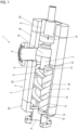
- the Figure 1 shows, partially in section, a screw pump 1 according to the invention, comprising a housing 2, which here consists of four housing parts 2a, 2b, 2c and 2d by way of example.
- the housing is therefore of modular construction.
- a pump chamber 3 is formed inside the housing, with an axial inlet 4 and a radial inlet 5.
- the delivery direction of the screw pump 1 is reversible, i.e., depending on the delivery direction, the inlet 4 can be the suction connection and the inlet 5 the pressure connection, or vice versa.
- an axial inlet 5 and a radial inlet 4 are shown here, the access configuration can also be different, e.g. with two radial inlets, which can also be offset around the longitudinal axis of the housing.
- the housing 2 also has a bearing chamber 6 in which, as will be described below, a drive spindle is mounted.
- the screw spindle pump 1 further comprises a spindle assembly comprising a centrally arranged drive spindle 7 with a drive spindle profile 8 and two laterally adjacent and offset by 180° from one another running spindles 9, each with a running spindle profile 10, wherein the drive spindle profile 8 meshes with the running spindle profiles 10.
- a spindle assembly comprising a centrally arranged drive spindle 7 with a drive spindle profile 8 and two laterally adjacent and offset by 180° from one another running spindles 9, each with a running spindle profile 10, wherein the drive spindle profile 8 meshes with the running spindle profiles 10.
- two running spindles 9 are shown; alternatively, only one running spindle 9 or three running spindles 9 can be provided.
- the drive spindle 7 or the drive spindle profile 8 is received in a corresponding drive spindle bore (not shown in detail here) in the housing 2 or in the housing part 2b, respectively, while the two running spindles 9 are received in corresponding running spindle bores 11 in the housing 2 or in the housing part 2b, respectively.
- the two running spindle bores 11 overlap with the drive spindle bore 9 in a known manner, whereby the bores form a substantial part of the pump chamber 3.
- the two housing parts 2a and 2c have corresponding housing shoulders 12 in the area of the two spindle bores 11, which serve as support surfaces for a thrust washer 13 each, which are axially spaced from one another and each accommodate a spindle 9 between them.
- Each thrust washer 13 forms a thrust surface for the end face of the axially adjacent spindle 9 or has such a thrust surface. They are flat on both sides, thus lying flat against the corresponding housing shoulders 12, just as they run parallel to the corresponding flat end faces of the spindles 9.
- Each spindle 9 is accommodated between the two thrust washers 13 with minimal axial play, depending on the size of the screw spindle pump, between 0.3 - 5.0 mm, in particular between 1.0 - 3.0 mm, and can therefore be slightly axially displaced.
- the maximum axial play is determined by the thickness of the thrust washers 13 used. adjusted so that it can be minimized and the dead space there can be minimized.
- the thrust washers 13 are, for example, washers made of a ceramic material or of a composite material containing a ceramic material, preferably of a technical ceramic.
- each thrust washer 13 can also be made of a carbide material, e.g. WC.
- the use of thrust washers 13 made of hard metal is also conceivable.
- Both the spindles and the housing are made of stainless steel, which is particularly suitable for use in the food industry, the medical, pharmaceutical and chemical industries.
- the drive spindle 7, as the partially sectioned figure shows, is led from the pump chamber 3 into the bearing chamber 6, where it is mounted in the housing 2 via a radial bearing 14, a rolling bearing preferably in the form of a single or multi-row ball bearing or a roller or spherical bearing. This provides the rotary bearing of the drive spindle 7 in a single bearing plane.
- a single such bearing plane is sufficient because, as will be discussed below, the drive spindle 7 is axially hydraulically balanced, meaning that no or only a negligible axial force acts on the drive spindle 7 during pump operation, as well as no or only a negligible radial force resulting from the symmetrical bilateral arrangement of the two running spindles 7, which in turn are hydraulically supported or mounted via a sliding film, both axially and radially, as will be discussed below.
- a single sealing element 15 is provided, which is preferably a radial mechanical seal, which is arranged on the drive spindle 7 and extends towards a corresponding sealing seat in the housing 2. Seals.
- This single spindle seal or sealing level seals the entire pump chamber 3 on this side, i.e., the drive side. This means that the fluid or medium can only flow from inlet 4 to inlet 5 or vice versa; passage to the bearing side or drive side (the actual pump drive is connected to the corresponding end-side impeller spindle connection) is excluded.
- the drive spindle 7 is axially hydraulically balanced so that no or only a completely negligible axial force acts on the drive spindle 7.
- This is achieved by designing the sealing element 15 accordingly with regard to the drive spindle profile 8.
- the design is such that the surface of the sealing element 15 pressurized with the medium, i.e., the surface facing the pump chamber 3, is essentially equal to the axially compressed surface of the work spindle profile 8.
- the axially compressed surface of the work spindle profile 8 viewed in the longitudinal direction of the spindle, results, in a known manner, from the meshing engagement of the work spindle profile 8 with the running spindle profiles 10, from several, partially sickle-shaped surface sections of the work spindle profile 7, which add up to a total surface.
- This total surface area is now almost, or ideally, completely, the same size as the axially compressed annular surface of the sealing element 15 facing the pump chamber. Any surface difference should be a maximum of 10%, preferably a maximum of 5%.
- the pressure acting on the respective surfaces is directed opposite to each other, so that, since both surfaces are subjected to the same pressure, ideally complete pressure equalization results. Consequently, the drive spindle 7 is virtually pressure-free or hydraulically balanced, so that ideally no or only a negligible axial force acts on it.
- the respective spindle bore 11 is provided with a sliding coating 16, which is preferably made of a plastic such as HNBR, EPDM, PTFE, CTFE, PFA, FKM, or FFKM.
- the thickness of the sliding coating 16 is selected such that only minimal radial play results between the respective spindle 9, i.e., its outer surface, and the sliding coating 16. This radial play should be between 0.01 - 1.0 mm, in particular between 0.05 - 0.5 mm. This means that only minimal play is present here, so that any backflow can be minimized, combined with an improvement in efficiency.
- a corresponding medium lubricating film is formed, via which the running spindles 9 are virtually slidingly mounted towards the sliding lining 16, so that here, too, no abrasion occurs.
- the drive spindle 7 is driven by the drive in a known manner; it rotates.
- the profile engagement inevitably causes the running spindles 9 to rotate and the medium to be conveyed accordingly from inlet 4 to inlet 5 or vice versa, i.e. from the suction port to the pressure port, depending on the direction of rotation of the drive spindle 7.
- the two running spindles 9 are minimally axially displaced as described by the build-up of working pressure and the resulting minimal axial play within the profile engagement; they each run against one of the thrust washers 13, where they are preferably slide-mounted via the resulting sliding film from the medium to be conveyed. Due to the minimal gap, there is only extremely low backflow, which leads to improved efficiency.
- a modular housing 2 comprising, for example, three housing parts 2a, 2b, 2c, and 2d.
- a pump chamber 3 is formed inside the housing, with an axial access 4 and a radial access 5.
- the delivery direction of the screw pump 1 is also reversible here.
- the housing 2 also has a bearing chamber 6, in which, as described below, a drive spindle is mounted.
- the screw spindle pump 1 also comprises a spindle package with a central drive spindle 7 with a drive spindle profile 8 and two laterally adjacent running spindles 9 arranged at a 180° angle to one another, each with a running spindle profile 10, wherein the drive spindle profile 8 meshes with the running spindle profiles 10.
- a spindle package with a central drive spindle 7 with a drive spindle profile 8 and two laterally adjacent running spindles 9 arranged at a 180° angle to one another, each with a running spindle profile 10, wherein the drive spindle profile 8 meshes with the running spindle profiles 10.
- two running spindles 9 are shown; alternatively, only one running spindle 9 or three running spindles 9 can be provided.
- the drive spindle 7 is received in a corresponding drive spindle bore in the housing 2, while the two idler spindles 9 are received in corresponding idler spindle bores 11 in the housing 2.
- the two idler spindle bores 11 overlap with the drive spindle bore 9 in a known manner, the bores in turn forming an essential part of the pump chamber 3.
- the two housing parts 2a and 2c have corresponding housing shoulders 12 in the area of the two spindle bores 11.
- the housing shoulders 12 are axially spaced from one another.
- a spindle 9 is accommodated between them.
- Each housing shoulder 12 is provided with a coating 17, which forms a contact surface for the end face of the axially adjacent spindle 9.
- the coating 17 is made of, for example, Si 3 N 4 , SiC, WC or Cr 2 O 3 and is applied directly to the respective housing shoulder 12.
- the end faces of the spindles 9 are flat, i.e., lie flat to or on the corresponding coatings 17 of the housing shoulders 12.
- Each idler spindle 9 is accommodated between the two housing shoulders 12 or the low-wear coatings 17 with minimal axial play, depending on the size of the screw spindle pump, between 0.3 - 5.0 mm, in particular between 1.0 - 3.0 mm, and can therefore be slightly axially displaced.
- the idler spindles 9 also run against the contact surfaces or coatings 17 and are ideally supported there by a hydraulic lubricating film or are slide-mounted. In any case, the coatings are extremely low-wear, as are the idler spindles themselves, ensuring long-term operation.
- the contact surfaces are realized directly on the housing itself by means of the coatings 17.
- the arrangement of the separate contact washers, as in the embodiment according to Fig. 1 is not required here. Nevertheless, the same advantages as in the example according to Fig. 1 described.
- Fig. 2 shown screw pump 1 the example from Fig. 1 , ie that here too a radial bearing 15 is provided for supporting the drive spindle 7, and at least the spindle bores 11 are covered with a sliding coating 16.
- the explanations for the pump from Fig. 1 is therefore referred to, they apply equally to the pump according to Fig. 2 .
- the screw pump according to the invention is clearly designed in a simple manner, as it does not require a device for hydraulic thrust compensation of the impeller spindles 7, which is disadvantageous when conveying foodstuffs or other hygienically sensitive media. Rather, the design of the The screw pump allows for cleaning in the assembled state, since there are no other volumes other than the pump chamber that could contain the fluid to be pumped. This allows for easy flushing of the screw pump in the installed state, i.e., "cleaning in place.” By integrating the thrust washers 13, the permissible axial play of the idler spindles 9 can be minimized. As mentioned, direct disk contact occurs, eliminating any disadvantageous dead space in this pump chamber area.
Landscapes
- Engineering & Computer Science (AREA)
- Mechanical Engineering (AREA)
- General Engineering & Computer Science (AREA)
- Rotary Pumps (AREA)
- Details And Applications Of Rotary Liquid Pumps (AREA)
- Reciprocating Pumps (AREA)
Description
- Die Erfindung betrifft eine Schraubenspindelpumpe, umfassend ein Gehäuse sowie eine darin aufgenommene Antriebsspindel und wenigstens eine mit dieser kämmende Laufspindel, die jeweils zwei endständige Stirnflächen aufweist. Schraubenspindelpumpen kommen zur Förderung unterschiedlichster Stoffe zum Einsatz, primär fluider Medien. Eine Schraubenspindelpumpe umfasst bekanntlich ein Gehäuse, in dem das Spindelpaket umfassend eine Antriebsspindel, die aus dem Gehäuse herausgeführt ist und mit einem Antriebsmotor, gegebenenfalls unter Zwischenschaltung eines Getriebes, gekoppelt ist, sowie eine oder mehrere Laufspindeln, deren Spindelprofile mit dem Spindelprofil der Antriebsspindel kämmen und die über die Antriebsspindel angetrieben werden. Das Gehäuse, in dem das Spindelpaket aufgenommen ist, kann das auch nach außen abschließende Pumpengehäuse sein, oder ein als Einsatz in ein Außengehäuse konzipiertes Gehäuse.
- Üblicherweise wird die eine oder werden die mehreren, zumeist zwei parallel und um 180° versetzt neben der Antriebsspindel angeordneten Laufspindel axial hydraulisch abgestützt, wozu benachbart zur Stirnfläche der jeweiligen Laufspindel eine Düsenblende vorgesehen sein kann, über die gegen die Spindelstirnfläche ein zugeleiteter Anteil des zu fördernden Fluids anströmt, um hierüber einen axialen Stützdruck aufzubauen, über den die jeweilige Laufspindel axial abgestützt wird. Dies bedingt eine entsprechende Ausbildung des Gehäuses, in dem eine entsprechende Fluidzufuhr über geeignete Kanäle vorgesehen werden muss, wie auch die entsprechenden Düsenblenden, die zur Erzeugung des entsprechenden Fluiddrucks auch geometrisch entsprechend konzipiert und ausgelegt werden müsser
- Die Dokumente
US 2 693 762 A ,DE 10 2006 049663 A1 ,US 2011/014079 A1 undDE 78 02 765 U1 offenbaren Schraubenspindelpumpen mit Maßnahmen zwecks Ausgleich und/oder Aufnahme axialer Kräfte. - Zunehmend werden Schraubenspindelpumpen auch im Lebensmittel- und Pharmaziebereich eingesetzt, das heißt, dass mit ihnen entsprechende fluide Lebensmittel oder pharmazeutische Stoffe gefördert werden. Die Arbeit mit solchen Stoffen erfordert ein Höchstmaß an Hygiene, weshalb auch die verwendeten Schraubenspindelpumpen in entsprechend kurzen Intervallen gereinigt werden müssen. Aufgrund der komplexen Ausgestaltung der Schraubenspindelpumpe im Hinblick auf die Fluidführung zur axialen Abstützung der Laufspindeln, die entsprechende Kanäle etc. umfasst, ist es zur Reinigung erforderlich, die Schraubenspindelpumpe auszubauen und zu demontieren und zu reinigen, um sicherzustellen, dass die Reinigung in allen Bereichen erfolgt. Denn aufgrund der Integration der zusätzlichen Kanäle, Düsenblenden etc. ist ein beachtliches Volumen gegeben, das am eigentlichen Förderprozess nicht teilnimmt, also quasi als Totraum vorhanden ist, gleichwohl aber mit dem Fluid beaufschlagt ist.
- Der Erfindung liegt damit das Problem zugrunde, eine verbesserte Schraubenspindelpumpe anzugeben.
- Zur Lösung dieses Problems sind bei einer Schraubenspindelpumpe der eingangs genannten Art erfindungsgemäß die Merkmale des unabhängigen Anspruchs 1 vorgesehen.
- Bei der erfindungsgemäßen Schraubenspindelpumpe ist kein hydraulischer axialer Schubausgleich für die Laufspindeln vorgesehen. Vielmehr ist der oder, wenn z.B. zwei Laufspindeln vorgesehen sind, jeder Laufspindel zumindest an einer Seite axial jeweils eine Anlauffläche zugeordnet, wobei die Laufspindel mit geringem Axialspiel zu dieser Anlauffläche aufgenommen ist. Diese Anlauffläche(en) befinden sich folglich im eigentlichen Pumpenraum. Im Betrieb wird die Antriebsspindel angetrieben. Aufgrund des Profileingriffs bzw. des hydraulischen Drucks rotiert auch die eine oder die beiden Laufspindeln mit der Antriebsspindel, so dass es zur Fluidförderung durch den Pumpenraum kommt. Die Antriebsspindel selbst ist weitgehend hydraulisch ausgeglichen, das heißt, dass betriebsbedingt keine oder eine vernachlässigbare Axialkraft auf die Antriebsspindel wirkt. Dies wird erreicht, indem die bedrückte, also unter Druck stehende Fläche eines die Antriebsspindel zum Gehäuse hin abdichtende Dichtelements und die bedrückte Profilfläche des Antriebsspindelprofils im Wesentlichen gleich sind. Da beide Flächen in unterschiedliche Richtungen axial bedrückt werden, stellt sich somit ein Kräftegleichgewicht ein, was dazu führt, dass die Antriebsspindel hydraulisch ausgeglichen ist. Im Betrieb erfahren die Laufspindeln nur einen aus dem Pumpendruck resultierenden geringen axialen Versatz in Richtung der oder einer der Anlaufflächen. Die Anlauffläche ist, wenn die Pumpe nicht reversierbar ist, an der Saugseite bzw. dem saugseitigen Ende der Laufspindel vorgesehen, da sich die Laufspindel im Betrieb geringfügig zur Saugseite verschiebt. Ist die Pumpe reversierbar, so sind pro Laufspindel zwei Anlaufflächen vorgesehen, um so je nach Förderrichtung und damit Bewegungsrichtung der Laufspindel an beiden Seiten eine Anlauffläche vorzusehen. Ist die Antriebsspindelpumpe hinsichtlich der Förderrichtung reversierbar, so erfolgt also dieser Versatz je nach Arbeitsrichtung entweder zur einen oder zur anderen Anlauffläche hin. Der Versatz ist aufgrund des geringen Axialspiels möglich, wobei das Axialspiel hinsichtlich des sich ergebenden, maximalen Versatzes ausgelegt werden kann. Die jeweilige Stirnfläche der Laufspindel kann im Betrieb gegen die jeweilige axiale Anlaufscheibe laufen, wo sie idealerweise über einen dünnen hydraulischen Schmierfilm gelagert ist oder, wenn sie gegen die Anlauffläche läuft, nur eine vernachlässigbare Reibung gegeben ist. Das heißt, dass es trotz Anlaufens gegen die Anlauffläche einerseits zu einer entsprechenden Lagerung und Schmierung über das zu fördernde Fluid kommt, nachdem wie beschrieben die Anlauffläche im Pumpenraum ist, und andererseits kein Verschleiß zu versorgen ist.
- Die erfindungsgemäße Schraubenspindelpumpe ermöglicht daher einerseits eine entsprechende axiale Abstützung der Laufspindeln, sieht hierfür jedoch keinerlei spezifische Maßnahmen außer die Integration zweier Anlaufscheiben vor. Das einzige Volumen, durch das das zu fördernde Fluid strömt, ist der Pumpenraum, der quasi totraumoptimiert ist. Dies wiederum führt dazu, dass die erfindungsgemäße Schraubenspindelpumpe im Falle einer Reinigung nicht demontiert werden muss, da der Reinigungsvorgang im eingebauten Zustand erfolgen kann, nachdem das Reinigungsfluid ohne Probleme den Pumpenraum entsprechend spülen kann. Das heißt, dass ein sogenanntes "Cleaning in Place (CIP)" mit der erfindungsgemäßen Schraubenspindelpumpe möglich ist.
- Wie bereits beschrieben, kann bei einer nicht reversierbaren Pumpe nur der saugseitigen Stirnfläche der Laufspindel oder jeder Laufspindel eine Anlauffläche zugeordnet sein. Bei einer reversierbaren Pumpe kann axial benachbart zu beiden Stirnflächen der Laufspindel eine Anlauffläche vorgesehen sein, wobei die Laufspindel dann mit axialem Spiel zwischen beiden Anlaufflächen aufgenommen ist.
- Wie beschrieben ist das Spindelpaket hydraulisch synchronisiert, das heißt, es stellt sich im Betrieb selbsttätig ein. Insbesondere ist keine respektive eine vernachlässigbare mechanische Kraftübertragung zwischen der Antriebs- und den Laufspindeln gegeben, resultierend in einem minimalen axialen Versatz der Laufspindeln im Betrieb. Daher kann das axiale Spiel zwischen der Laufspindel und den axialen Anlaufflächen auch entsprechend gering ausgelegt werden, natürlich je nach gegebener Baugröße der Schraubenspindelpumpe. Das axiale Spiel liegt bevorzugt zwischen 0,3 mm bei Schraubenspindelpumpen kleiner Baugröße und 5,0 mm bei Schraubenspindelpumpen sehr großer Baugröße, bevorzugt liegt das Spiel im Bereich zwischen 1,0 - 3,0 mm. Das Spiel wird im Hinblick auf den gegebenen axialen Versatz der Laufspindeln ausgelegt, wobei es sich bei den angegebenen Werten jeweils um das Gesamtspiel handelt, das die jeweilige Laufspindel zwischen beiden Anlaufscheiben hat.
- Hinsichtlich der Realisierung der Anlaufflächen sind verschiedene Möglichkeiten vorgesehen. So kann die oder jede Anlauffläche mittels einer Beschichtung am Gehäuse ausgebildet ist. Hier sind also gehäuseseitig eine oder mehrere entsprechende Gehäuseschultern vorgesehen, die die Basis für die Anlauffläche bilden, welche mittels einer Beschichtung der Gehäuseschulter realisiert ist. Alternativ kann die oder jede Anlauffläche auch mittels einer Anlaufscheibe realisiert ist. Hier wird also zur Realisierung der Anlauffläche eine spezifische Anlaufscheibe in das Gehäuse an eine entsprechende Position eingesetzt. Über die Dicke der Anlaufscheibe kann das Spiel sehr exakt eingestellt werden.
- Als Anlauflächen werden bevorzugt äußerst verschleißarme Flächen vorgesehen, das heißt, dass ein entsprechendes verschleißarmes Material verwendet wird. Hierfür eignen sich Beschichtungen oder Anlaufscheiben aus einem keramischen oder karbidischen Material oder aus einem keramisches oder karbidisches Material enthaltenden Verbundwerkstoff. Das heißt, dass grundsätzlich eine technische Keramik verwendet wird, die gegebenenfalls mit Glas- oder Kohlenstofffasern verstärkt sein kann. Zweckmäßigerweise wird ein keramisches Material respektive eine technische Keramik auf Siliziumbasis verwendet, wobei sich hierfür insbesondere SiC oder Si3N4 eignet, oder WC, welches Material wie beschrieben bei Bedarf auch faserverstärkt sein kann. Denkbar ist auch die Verwendung von Cr2O3. Alternativ kann auch zur Bildung der Beschichtung ein Hartmetall verwendet werden, wie auch die Anlaufscheibe(n) aus Hartmetall sein können bzw. gehärtete Oberflächen aufweisen können. Die Härte sollte wenigstens 1000 HV betragen. Die Anlaufflächen bzw. die Beschichtungen oder Axialscheiben neigen daher nicht zum Verschleiß, ähnlich wie die aus Stahl gefertigten und bevorzugt kolsterisierten oder kaltnitrierten Laufspindeln, die wie beschrieben idealerweise über den hydrostatischen Schmierfilm auf den Anlaufflächen bzw. Beschichtungen oder Anlaufscheiben gleitgelagert sind.
- Die oder jede Laufspindel ist in einer entsprechenden Laufspindelbohrung aufgenommen, die mit einer die Antriebsspindel aufnehmenden Antriebsspindelbohrung überlappt, wobei die eine oder die beiden Laufspindelbohrungen über eine oder zwei axiale Gehäuseschultern axial begrenzt sind, an welcher oder welchen Gehäuseschultern die jeweilige Anlauffläche ausgebildet oder Anlaufscheibe abgestützt ist. Im Gehäuse ist oder sind demzufolge definierte, Schultern vorgesehen, die entweder als Träger für die Beschichtung(en) oder als axiale Stützstellen für die Anlaufscheiben dienen. Entweder ist also auf einer solchen Gehäuseschulter unmittelbar die Beschichtung aufgebracht, oder an einer solchen Gehäuseschulter liegt eine Anlaufscheibe an. Dabei kann der axiale Abstand zweier Gehäuseschultern sehr genau definiert und eingestellt werden, so dass sich definierte geometrische Verhältnisse einstellen und auch das axiale Spiel der jeweilgen Laufspindel bei Verwendung separater Anlaufscheiben durch Wahl der entsprechenden Anlaufscheibendicken entsprechend exakt eingestellt werden kann.
- Wie beschrieben ist die Antriebsspindel hydraulisch ausgeglichen derart, dass keine nennenswerte, die Antriebsspindel in eine Richtung schiebende Axialkraft auf die Antriebsspindel wirkt, die dann wiederum zu einem Verschub der Laufspindeln führen würde. Die quasi axial fliegend gelagerten Laufspindeln werden allein durch den sich im Pumpengehäuse aufbauenden Druck geringfügig unter Ausnutzung des Axialspiels axial bewegt, soweit es der Profileingriff erlaubt. Die Antriebs- und die Laufspindeln sind dabei in einem Pumpenraum aufgenommen, der über ein Dichtelement, bevorzugt ein einzelnes Dichtelement, das zwischen der Antriebsspindel und dem Gehäuse abdichtet, zu einer Antriebsseite der Antriebsspindel hin abgedichtet ist. Das heißt, dass der Pumpenraum zu einer Seite über nur ein Dichtelement abgedichtet ist. Dieses Dichtelement ist nun erfindungsgemäß derart in Bezug auf die Dimension und Geometrie der Antriebsspindel gewählt bzw. ausgelegt, dass die axial bedrückte Fläche des Dichtelements im Wesentlichen der axial bedrückten Fläche der Antriebsspindel respektive des Antriebsspindelprofils entspricht. Hierüber erfolgt der axiale hydraulische Ausgleich, der sich als besonders vorteilhaft erwiesen hat im Hinblick auf eine hydraulische Synchronisierung des Spindelpakets und die Minimierung des sich ergebenden axialen Laufspindelversatzes im Betrieb. Die bedrückte Fläche des von der Antriebsspindel durchsetzten ringförmigen Dichtelements entspricht letztlich seiner axialen, zum Pumpenraum weisenden Ringfläche. Die bedrückte Fläche der Antriebsspindel setzt sich, gesehen in Spindellängsrichtung, wie bekannt durch mehrere, zum Teil auch sichelförmige Flächenabschnitte des vom Spindelkern radial abstehenden Spindelprofils zusammen, resultierend aus dem Eingriff des Spindelprofils in die beiden Spindelprofile der Laufspindeln. Der Unterschied der beiden bedrückten Flächen sollte maximal 10%, vorzugsweise nur maximal 5% betragen, und idealerweise natürlich Null sein, so dass sich, wenn überhaupt, nur eine sehr geringe resultierende Axialkraft einstellt, die weder einen Axialversatz der Antriebsspindel noch eine nennenswerte Belastung der Spindellagerung bewirkt.
- Das Dichtelement selbst ist bevorzugt eine Gleitringdichtung, die an der Antriebsspindel angeordnet ist und zu einem entsprechenden Dichtabschnitt oder Dichtsitz an dem Gehäuse hin abdichtet.
- Die Antriebsspindel selbst ist zweckmäßigerweise nur an einer Seite außerhalb eines die Arbeits- und Laufspindeln aufweisenden Pumpenraums, aus dem die Antriebsspindel mit einem Abschnitt herausgeführt ist, im Gehäuse radial drehgelagert. Hierfür kommt zweckmäßigerweise ein Radiallager zum Einsatz, wobei bevorzugt nur ein einziges Radiallager verwendet wird. Bei diesem kann es sich um ein ein- oder mehrreihiges Lager in Form eines Kugel-, Rollen- oder Tonnenlagers etc., also ein Wälzlager, handeln. Aufgrund des einerseits gegebenen hydraulischen Ausgleichs der Antriebsspindel sowie der Anordnung zweier Laufspindeln, die um 180° versetzt neben der Antriebsspindel angeordnet sind, ist es möglich, nur ein einfaches Radiallager zu verwenden, da dieses aufgrund des entsprechenden Kräfteausgleichs im Betrieb nahezu lastfrei ist.
- Eine zweckmäßige Weiterbildung der Erfindung sieht vor, dass zumindest die oder jede Laufspindelbohrung mit einem Gleitbelag ausgekleidet ist, wobei die Laufspindeln mit radialem Spiel zu dem Gleitbelag angeordnet sind. Auch die Auskleidung der Laufspindelbohrungen mit dem Gleitbelag dient der Reduzierung etwaigen Totraums. Denn im Normalbetrieb kommt es zu keinen Radialbewegungen der Laufspindeln, vielmehr bildet sich zwischen der Spindelmantelfläche und den Laufspindelbohrungen respektive dem Gleitbelag ebenfalls ein dünner hydraulischer Schmierfilm aus, der die Laufspindel lagert. Dies ermöglicht es nun wiederum über den Gleitbelag das radiale Laufspindelspiel entsprechend zu minimieren und auch hierüber den Totraum entsprechend zu reduzieren.
- Als ein solcher Gleitbelag wird zweckmäßigerweise ein Kunststoffbelag verwendet, insbesondere aus einem hydrierten Acrylnitrilbutadien-Kautschuk (HNBR), Chlortrifluorethen, einem Ethylen-Propylen-Dien-(Monomer)-Kautschuk (EPDM), Polytetrafluorethylen (PTFE), einem Perfluoralkoxy-Polymer, einem Fluorkautschuk (FKM) oder einem Perfluorkautschuk (FFKM). Diese Aufzählung ist jedoch nicht abschließend, vielmehr können auch andere geeignete Kunststoffmaterialien, solange sie für den Einsatz im Hinblick auf das zu fördernde Medium geeignet sind, verwendet werden.
- Die Dicke des Gleitbelags wird bevorzugt derart eingestellt, dass das radiale Spiel zwischen 0,01 - 1,00 mm, insbesondere zwischen 0,05 - 0,5 mm beträgt. Das heißt, dass hier ein äußerst geringes Radialspiel gegeben ist, resultierend eben aus dem Umstand, dass es im Betrieb zu keinem nennenswerten Radialbewegen kommt.
- Neben der totraumoptimierten Auslegung der Schraubenspindelpumpe hat die Auslegung der Schraubenspindelpumpe im Hinblick auf die Minimierung des Axialspiels wie auch des Radialspiels ferner den Vorteil, dass sich der Wirkungsgrad der Schraubenspindelpumpe im Vergleich zu bisher üblichen Schraubenspindelpumpen deutlich, bis hin zu mehreren 10 %, erhöhen lässt. Denn es stellt sich aufgrund der minimalen Spiele ein gleichbleibender Volumenstrom über einen weiten Druckbereich ein, wobei es kaum zu einer Rückströmung des geförderten Mediums kommt, da die gegebenen Spalte minimal sind. Das heißt, dass ein deutlich effizienterer Förderbetrieb realisiert werden kann, verbunden mit einer in hygienischer Sicht äußerst vorteilhaften Ausgestaltung der Schraubenspindelpumpe.
- Wie beschrieben dient die Schraubenspindelpumpe insbesondere zur Förderung kritischer Substanzen, bei deren Verarbeitung ein Höchstmaß an Sauberkeit erforderlich ist. Demgemäß wird die erfindungsgemäße Schraubenspindelpumpe zur Förderung zähflüssiger oder pastöser Lebensmittel, pharmazeutischer, kosmetischer oder chemischer Mittel verwendet. Zähflüssige oder pastöse Lebensmittel können beispielsweise Molkereiprodukte wie Frischkäse, Sahne, Rahm, Quark, Butter oder Joghurt sein. Auch die Förderung deutlich viskoserer oder pastöser Lebensmittel wie Ketchup, Mayonnaise, Senf und ähnliches, Meerrettich, Schmelzkäse, Pflanzenöle, Flüssig-Ei, Teig oder Fruchtmus ist denkbar, wie auch von Gelatine, Sirup, Nuss- oder Nougatcremes, Schokolade, Honig, Marzipan oder sonstiger Fette oder Öle. Im pharmazeutischen und kosmetischen Bereich sind als förderbare Medien beispielsweise Flüssigseifen, Cremes oder Lotionen oder ähnliches zu nennen. Im chemischen Bereich sind exemplarisch Flüssigwaschmittel, Spülmittel, Reinigungsmittel, aber auch Lacke oder ähnliches zu nennen. Auch hier ist die Aufzählung natürlich nicht abschließend, zeigt aber, dass die Viskosität der förderbaren Materialien sich über eine extrem große Bandbreite erstreckt. Die Viskosität der förderbaren Stoffe, zu deren Förderung die erfindungsgemäße Schraubenspindelpumpe verwendet werden kann, liegt im Bereich zwischen 0,5 - 1 Million kg•m-1•s-1.
- Weitere Vorteile und Einzelheiten der Erfindung ergeben sich aus dem nachfolgend beschriebenen Ausführungsbeispiel sowie der Zeichnung. Dabei zeigen:
- Fig. 1
- eine Prinzipdarstellung einer erfindungsgemäßen Schraubenspindelpumpe einer ersten Ausführungsform, im Viertelschnitt, und
- Fig. 2
- eine Prinzipdarstellung einer erfindungsgemäßen Schraubenspindelpumpe einer zweiten Ausführungsform, im Viertelschnitt.
- Die
Figur 1 zeigt, teilgeschnitten, eine erfindungsgemäße Schraubenspindelpumpe 1, umfassend ein Gehäuse 2, das hier exemplarisch aus vier Gehäuseteilen 2a, 2b, 2c und 2d besteht. Das Gehäuse ist also modular aufgebaut. Im Gehäuseinneren ist ein Pumpenraum 3 ausgebildet, mit einem axialen Zugang 4 sowie einem radialen Zugang 5. Die Förderrichtung der Schraubenspindelpumpe 1 ist reversierbar, das heißt, dass es sich je nach Förderrichtung bei dem Zugang 4 um den Sauganschluss und bei dem Zugang 5 um den Druckanschluss handeln kann, oder umgekehrt. Wenngleich hier ein axialer Zugang 5 und ein radialer Zugang 4 gezeigt sind, kann die Zugangskonfiguration auch anders sein, z.B. mit zwei radialen Zugängen, die auch um die Gehäuselängsachse versetzt sein können. - Das Gehäuse 2 weist neben dem Druckraum 3 auch einen Lagerraum 6 auf, in dem, wie nachfolgend noch beschrieben wird, die Lagerung einer Antriebsspindel erfolgt.
- Die Schraubenspindelpumpe 1 umfasst des Weiteren ein Spindelpaket, umfassend eine mittig angeordnete Antriebsspindel 7 mit einem Antriebspindelprofil 8 sowie zwei seitlich benachbart und um 180° zueinander versetzt angeordnete Laufspindeln 9 mit jeweils einem Laufspindelprofil 10, wobei das Antriebsspindelprofil 8 mit den Laufspindelprofilen 10 kämmt. Im Beispiel sind zwei Laufspindeln 9 gezeigt, alternativ kann auch nur eine Laufspindel 9 oder drei Laufspindeln 9 vorgesehen sein.
- Die Antriebsspindel 7 respektive das Antriebsspindelprofil 8 ist in einer entsprechenden, hier nicht näher gezeigten Antriebsspindelbohrung im Gehäuse 2 respektive im Gehäuseteil 2b aufgenommen, während die beiden Laufspindeln 9 in entsprechenden Laufspindelbohrungen 11 im Gehäuse 2 respektive im Gehäuseteil 2b aufgenommen sind. Die beiden Laufspindelbohrungen 11 überlappen mit der Antriebsspindelbohrung 9 in bekannter Weise, wobei die Bohrungen einen wesentlichen Teil des Pumpenraums 3 bilden.
- Die beiden Gehäuseteile 2a und 2c weisen im Bereich der beiden Laufspindelbohrungen 11 entsprechende Gehäuseschultern 12 auf, die als Stützflächen für jeweils eine Anlaufscheibe 13 dienen, die axial voneinander beabstandet sind und zwischen sich jeweils eine Laufspindel 9 aufnehmen. Jede Anlaufscheibe 13 bildet eine Anlauffläche für die Stirnfläche der axial benachbarten Laufspindel 9 bzw. weist eine solche Anlauffläche auf. Sie sind an beiden Seiten ebenflächig, liegen also ebenflächig an den entsprechenden Gehäuseschultern 12 an, wie sie auch flächenparallel zu den entsprechenden ebenen Stirnflächen der Laufspindeln 9 verlaufen. Jede Laufspindel 9 ist mit geringem Axialspiel, je nach Baugröße der Schraubenspindelpumpe zwischen 0,3 - 5,0 mm, insbesondere zwischen 1,0 - 3,0 mm, zwischen den beiden Anlaufscheiben 13 aufgenommen, kann also geringfügig axial verschoben werden. Das maximale Axialspiel wird über die Dicke der eingesetzten Anlaufscheiben 13 eingestellt, so dass es minimiert werden kann und der dortige Totraum minimiert werden kann.
- Bei den Anlaufscheiben 13 handelt es sich z.B. um Scheiben aus einem keramischen Material oder aus einem keramisches Material enthaltenden Verbundwerkstoff, bevorzugt aus einer technischen Keramik. Bevorzugt kommt ein Material auf Siliziumbasis, insbesondere SiC oder Si3N4 zum Einsatz. Alternativ kann jede Anlaufscheibe 13 auch aus einem karbidischen Material, z.B. WC sein. Auch der Einsatz von Anlaufscheiben 13 aus Hartmetall ist denkbar. Es handelt sich also um äußerst verschleißarme Anlaufscheiben 13, wobei auch die jeweilige Laufspindel 9, die aus einem entsprechenden, z.B. kolsterisierten oder kaltnitrierten Edelstahl gefertigt ist, entsprechend verschleißfest ist. Sowohl die Spindeln als auch das Gehäuse sind aus einem nichtrostenden Edelstahl gefertigt, der insbesondere für den Einsatz in der Lebensmittelindustrie, der medizinischen, pharmazeutischen und der chemischen Industrie geeignet ist.
- Die Antriebsspindel 7 ist, wie die teilgeschnittene Figur zeigt, aus dem Pumpenraum 3 in den Lagerraum 6 geführt, wo sie über ein Radiallager 14, ein Wälzlager vorzugsweise in Form eines ein- oder mehrreihigen Kugellagers oder eines Rollen- oder Tonnenlagers, im Gehäuse 2 gelagert ist. Hierüber erfolgt also in einer einzigen Lagerebene die Drehlagerung der Antriebsspindel 7. Eine einzige solche Lagerebene ist ausreichend, da, worauf nachfolgend noch eingegangen wird, die Antriebsspindel 7 axial hydraulisch ausgeglichen ist, mithin also keine oder nur eine vernachlässigbare axiale Kraft im Pumpenbetrieb auf die Antriebsspindel 7 wirkt, wie aber auch keine bzw. nur eine vernachlässigbare radiale Kraft, resultierend aus der symmetrischen beidseitigen Anordnung der beiden Laufspindeln 7, die ihrerseits hydraulisch abgestützt respektive über einen Gleitfilm gelagert sind, und zwar sowohl axial als auch radial, worauf nachfolgend noch eingegangen wird.
- Des Weiteren ist ein einziges Dichtelement 15 vorgesehen, bei dem es sich bevorzugt um eine radiale Gleitringdichtung handelt, die an der Antriebsspindel 7 angeordnet ist und zu einem entsprechenden Dichtsitz im Gehäuse 2 hin abdichtet. Über diese eine Spindelabdichtung respektive Dichtungsebene ist der gesamte Pumpenraum 3 zu dieser Seite hin, also zur Antriebsseite hin, abgedichtet. Das heißt, dass das Fluid oder Medium nur vom Zugang 4 zum Zugang 5 respektive umgekehrt strömen kann, ein Durchtritt hin zur Lagerseite respektive Antriebsseite (an dem entsprechenden endseitigen Laufspindelstutzen ist der eigentliche Pumpenantrieb angeschlossen) ist ausgeschlossen.
- Wie beschrieben ist die Antriebsspindel 7 axial hydraulisch ausgeglichen, so dass keine oder nur eine völlig vernachlässigbare Axialkraft auf die Antriebsspindel 7 wirkt. Dies wird erreicht, indem das Dichtelement 15 entsprechend im Hinblick auf das Antriebsspindelprofil 8 ausgelegt wird. Die Auslegung ist derart, dass die mit dem Medium druckbeaufschlagte Fläche des Dichtelements 15, also quasi die zum Pumpenraum 3 hinweisende Fläche, im Wesentlichen gleich der axial bedrückten Fläche des Arbeitsspindelprofils 8 ist. Die axial bedrückte Fläche des Arbeitsspindelprofils 8, in Spindellängsrichtung gesehene, ergibt sich, in bekannter Weise resultierend durch den kämmenden Eingriff des Arbeitsspindelprofils 8 in die Laufspindelprofile 10, durch mehrere, teilweise sichelförmige Flächenabschnitte des Arbeitsspindelprofils 7, die sich zu einer Gesamtfläche aufsummieren. Diese Gesamtfläche ist nun nahezu oder idealerweise komplett gleich groß wie die zum Pumpenraum weisende, axial bedrückte ringförmige Fläche des Dichtelements 15. Ein etwaiger Flächenunterschied sollte maximal 10%, vorzugsweise maximal 5% betragen. Der auf die jeweiligen Flächen wirkende Druck ist jeweils entgegengesetzt zueinander gerichtet, so dass sich, da beide Flächen mit dem gleichen Druck beaufschlagt sind, ein idealerweise vollständiger Druckausgleich ergibt und demzufolge die Antriebsspindel 7 quasi druckfrei respektive hydraulisch ausgeglichen ist, so dass idealerweise keine oder nur eine vernachlässigbare Axialkraft auf sie wirkt.
- Hieraus resultiert, dass damit aber auch auf die beiden Laufspindeln keine mechanische Kraftübertragung von der Antriebsspindel 7 her gegeben ist, da diese im Betrieb axial positionsfest ist. Einzig und allein ein arbeitsdruckbedingter geringer axialer Verschub der Laufspindeln 9 stellt sich ein, was zu einer geringen Axialbewegung der Laufspindeln 9 in den Laufspindelbohrungen 11 führt und zu einem Anlaufen der entsprechenden Stirnfläche der jeweiligen Laufspindel 9 gegen die jeweilige Anlaufscheibe 13. Die beiden gegeneinander laufenden Flächen sind bevorzugt über einen dünnen Schmierfilm des zu fördernden Mediums hydrostatisch gleitgelagert, so dass es in diesem Bereich zu keinem Verschleiß kommt.
- Zur weiteren Minimierung des Totraums und zur Verbesserung des Wirkungsgrades, resultierend aus einer Minimierung des Mediumrückflusses über gegebene Spalte, ist des Weiteren die jeweilige Laufspindelbohrung 11 mit einem Gleitbelag 16 versehen, bei dem es sich bevorzugt um einen Gleitbelag 16 aus einem Kunststoff wie HNBR, EPDM, PTFE, CTFE, PFA, FKM oder FFKM handelt. Die Dicke des Gleitbelags 16 ist derart gewählt, dass sich nur ein minimales Radialspiel zwischen der jeweiligen Laufspindel 9, also ihrer äußeren Mantelfläche, und dem Gleitbelag 16 ergibt, wobei dieses radiale Spiel zwischen 0,01 - 1,0 mm, insbesondere zwischen 0,05 - 0,5 mm, liegen sollte. Das heißt, dass auch hier nur ein minimales Spiel gegeben ist, so dass sich ein etwaiger Rückfluss minimieren lässt, verbunden mit einer Verbesserung des Wirkungsgrades. Auch hier stellt sich quasi ein entsprechender Mediumschmierfilm ein, über den die Laufspindeln 9 zum Gleitbelag 16 hin quasi gleitgelagert sind, so dass es auch hier zu keinem Abrieb kommt.
- Im Betrieb wird in bekannter Weise die Antriebsspindel 7 über den Antrieb angetrieben, sie rotiert. Über den Profileingriff kommt es zwangsläufig zu einer Rotation auch der Laufspindeln 9 und der entsprechenden Förderung des Mediums vom Zugang 4 zum Zugang 5 oder umgekehrt, also vom Sauganschluss zum Druckanschluss, je nach Drehrichtung der Antriebsspindel 7. Beim Anlaufen werden die beiden Laufspindeln 9 wie beschrieben durch den Aufbau des Arbeitsdrucks und resultierend aus dem minimalen Axialspiel innerhalb des Profileingriffs minimal axial verschoben, sie laufen jeweils gegen eine der Anlaufscheiben 13, wo sie bevorzugt über den sich gegebenen Gleitfilm aus dem zu fördernden Medium gleitgelagert sind. Aufgrund der minimalen Spalte stellt sich ein nur äußerst geringer Rückstrom ein, was zur Verbesserung des Wirkungsgrads führt.
- Das Ausführungsbeispiel der Schraubenspindelpumpe 1 gemäß
Fig. 2 entspricht vom Grundaufbau dem ausFig. 1 . Auch hier ist ein modulares Gehäuse 2 umfassend exemplarisch drei Gehäuseteilen 2a, 2b, 2c und 2d vorgesehen. Im Gehäuseinneren ist ein Pumpenraum 3 ausgebildet, mit einem axialen Zugang 4 sowie einem radialen Zugang 5. Die Förderrichtung der Schraubenspindelpumpe 1 ist auch hier reversierbar. Das Gehäuse 2 weist neben dem Druckraum 3 auch einen Lagerraum 6 auf, in dem, wie nachfolgend noch beschrieben wird, die Lagerung einer Antriebsspindel erfolgt. - Die Schraubenspindelpumpe 1 umfasst auch hier ein Spindelpaket mit einer mittigen Antriebsspindel 7 mit einem Antriebspindelprofil 8 sowie zwei seitlich benachbarten und um 180° zueinander versetzt angeordneten Laufspindeln 9 mit jeweils einem Laufspindelprofil 10, wobei das Antriebsspindelprofil 8 mit den Laufspindelprofilen 10 kämmt. Im Beispiel sind zwei Laufspindeln 9 gezeigt, alternativ kann auch nur eine Laufspindel 9 oder drei Laufspindeln 9 vorgesehen sein.
- Die Antriebsspindel 7 ist in einer entsprechenden Antriebsspindelbohrung im Gehäuse 2 aufgenommen, während die beiden Laufspindeln 9 in entsprechenden Laufspindelbohrungen 11 im Gehäuse 2 aufgenommen sind. Die beiden Lauspindelbohrungen 11 überlappen mit der Antriebsspindelbohrung 9 in bekannter Weise, wobei die Bohrungen wiederum einen wesentlichen Teil des Pumpenraums 3 bilden.
- Die beiden Gehäuseteile 2a und 2c weisen im Bereich der beiden Laufspindelbohrungen 11 entsprechende Gehäuseschultern 12 auf. Die Gehäuseschultern 12 sind axial voneinander beabstandet sind. Zwischen ihnen ist jeweils eine Laufspindel 9 aufgenommen. Jede Gehäuseschulter 12 ist mit einer Beschichtung 17 versehen, die eine Anlauffläche für die Stirnfläche der axial benachbarten Laufspindel 9 bildet. Die Beschichtung 17 ist z.B. aus Si3N4, SiC, WC oder Cr2O3 und unmittelbar auf die jeweilige Gehäuseschulter 12 aufgebracht. Die Stirnflächen der Laufspindeln 9 sind ebenflächig, liegen also ebenflächig zu bzw. an den entsprechenden Beschichtungen 17 der Gehäuseschultern 12 an. Jede Laufspindel 9 ist mit geringem Axialspiel, je nach Baugröße der Schraubenspindelpumpe zwischen 0,3 - 5,0 mm, insbesondere zwischen 1,0 - 3,0 mm, zwischen den beiden Gehäuseschultern 12 bzw. den verschleißarmen Beschichtungen 17 aufgenommen, kann also geringfügig axial verschoben werden. Im Betrieb laufen die Laufspindeln 9 auch hier gegen die Anlaufflächen bzw. Beschichtungen 17 und sind idealerweise dort über einen hydraulischen Schmierfilm abgestützt bzw. gleitgelagert. In jedem Fall sind die Beschichtungen äußerst verschleißarm, wie auch die Laufspindeln selbst, so dass ein dauerhafter Betrieb sichergestellt ist.
- Hier werden also die Anlaufflächen mittels der Beschichtungen 17 unmittelbar am Gehäuse selbst realisiert. Die Anordnung der separaten Anlaufscheiben, wie im Ausführungsbeispiel nach
Fig. 1 , ist hier nicht erforderlich. Gleichwohl werden die gleichen Vorteile wie zum Ausführungsbeispiel nachFig. 1 beschrieben erreicht. - Im Übrigen entspricht der Aufbau der in
Fig. 2 gezeigten Schraubenspindelpumpe 1 dem Beispiel ausFig. 1 , d.h., dass auch hier ein Radiallager 15 zur Lagerung der Antriebsspindel 7 vorgesehen ist, wie auch zumindest die Laufspindelbohrungen 11 mit einem Gleitbelag 16 belegt sind. Auf die Ausführungen zur Pumpe ausFig. 1 wird daher verwiesen, sie gelten gleichermaßen für die Pumpe nachFig. 2 . - Für den Fall, dass die Schraubenspindelpumpe 1 nicht reversibel ist, ist pro Laufspindelbohrung 11 nur eine die Anlauffläche bildende Anlaufscheibe 13 bzw. Beschichtung 17 vorgesehen, und zwar am saugseitigen Ende der jeweiligen Laufspindelbohrung, nachdem die Laufspindel 9 sich im Betrieb minimal zur Saugseite hin bewegt.
- Ersichtlich ist die erfindungsgemäße Schraubenspindelpumpe einfach konzipiert, da sie ohne eine Einrichtung zum hydraulischen Schubausgleich der Laufspindeln 7 auskommt, die bei einer Förderung von Lebensmitteln oder anderen hygienisch sensiblen Medien nachteilig ist. Vielmehr erlaubt es die Ausgestaltung der Schraubenspindelpumpe, sie im montierten Zustand reinigen zu können, da außer dem Pumpenraum keine sonstigen Volumina gegeben sind, in denen das zu fördernde Medium enthalten sein kann. Dies ermöglicht eine einfache Spülung der Schraubenspindelpumpe im verbauten Zustand, also ein "Cleaning-in-Place". Durch die Integration der Anlaufscheiben 13 kann das zulässige Axialspiel der Laufspindeln 9 minimiert werden, wobei wie gesagt ein direkter Scheibenanlauf erfolgt, so dass kein nachteiliger Totraum in diesem Pumpenraumbereich gegeben ist.
- Durch die Verwendung dreier Spindeln, nämlich der Antriebsspindel 7 sowie der beiden Laufspindeln 9, wird eine drucksteifere Förderkennlinie ermöglicht, da die Schraubenspindelpumpe 1 über ein sehr dichtes Profil verfügt. Dies ermöglicht Anwendungen mit hoher Dosiergenauigkeit. Durch das dichte Profil ergibt sich auch ein besseres Saugverhalten, resultierend in einer Verbesserung des Wirkungsgrads. Darüber hinaus ist die Schraubenspindelpumpe 1 respektive das Spindelpaket auch hydraulisch synchronisiert, stellt sich also im Betrieb selbsttätig ein, wobei keine mechanische Kraftübertragung zwischen der Antriebsspindel 7 und den Laufspindeln 9 gegeben ist.
Claims (15)
- Schraubenspindelpumpe umfassend wenigstens eine Laufspindel ohne hydraulischem axialem Schubausgleich, umfassend ein Gehäuse (2) mit einem Pumpenraum (3) sowie eine darin aufgenommene Antriebsspindel (7) und die wenigstens eine mit dieser kämmende Laufspindel (9), die jeweils zwei endständige Stirnflächen aufweist, dadurch gekennzeichnet, dass die Antriebsspindel (7) hydraulisch derart ausgeglichen ist, dass im Pumpenbetrieb keine oder nur eine vernachlässigbare Axialkraft auf die Antriebsspindel (7) wirkt, wobei der Pumpenraum (3) über ein an der Antriebsspindel angeordnetes Dichtelement (15) zwischen der Antriebsspindel (7) und dem Gehäuse (2) zu einer Antriebsseite der Antriebsspindel hin abgedichtet ist, wobei die zum Pumpenraum (3) weisende Fläche des Dichtelements (15), die von einem geförderten Medium axial bedrückt wird, im wesentlichen gleich der Größe der von dem Medium axial bedrückten Fläche eines Antriebsspindelprofils (8) ist, welches Antriebsspindelprofil (8) radial von einem Spindelkern absteht, und dass axial benachbart zu wenigstens einer Stirnfläche der Laufspindel (9) eine Anlauffläche (13) vorgesehen ist, wobei die Laufspindel (9) mit axialem Spiel senkrecht zur Anlauffläche (13) und gegen die Anlauffläche (13) verschiebbar aufgenommen ist.
- Schraubenspindelpumpe nach Anspruch 1, dadurch gekennzeichnet, dass axial benachbart zu beiden Stirnflächen der Laufspindel eine Anlauffläche vorgesehen ist, wobei die Laufspindel (9) mit axialem Spiel zwischen beiden Anlaufflächen aufgenommen ist.
- Schraubenspindelpumpe nach Anspruch 1 oder 2, dadurch gekennzeichnet, dass das axiale Spiel zwischen 0,3 - 5,0 mm, insbesondere zwischen 1,0 - 3,0 mm beträgt.
- Schraubenspindelpumpe nach einem der vorangehenden Ansprüche,
dadurch gekennzeichnet, dass die oder jede Anlauffläche mittels einer Beschichtung am Gehäuse ausgebildet ist, oder dass die oder jede Anlauffläche mittels einer Anlaufscheibe realisiert ist. - Schraubenspindelpumpe nach Anspruch 4, dadurch gekennzeichnet, dass die oder jede Beschichtung oder die oder jede Anlaufscheibe aus einem keramischen oder karbidischen Material oder einem Hartmetall oder einem keramisches oder karbidisches Material enthaltenden Verbundwerkstoff besteht.
- Schraubenspindelpumpe nach Anspruch 4 oder 5, dadurch
gekennzeichnet, dass die oder jede Beschichtung oder die oder jede Anlaufscheibe aus einem Material auf Siliziumbasis, insbesondere SiC oder Si3N4, aus WC oder aus Cr2O3 ist. - Schraubenspindelpumpe nach einem der vorangehenden Ansprüche,
dadurch gekennzeichnet, dass die oder jede Laufspindel (9) in einer Laufspindelbohrung (11), die mit einer die Antriebsspindel (7) aufnehmenden Antriebsspindelbohrung überlappen, aufgenommen ist, wobei die Laufspindelbohrungen (11) über eine oder zwei axiale Gehäuseschultern (12) axial begrenzt sind, an welcher oder welchen Gehäuseschultern (12) die Anlauffläche ausgebildet oder die Anlaufscheibe (13) abgestützt ist. - Schraubenspindelpumpe nach einem der vorangehenden Ansprüche,
dadurch gekennzeichnet, dass das Dichtelement (15) eine Gleitringdichtung ist. - Schraubenspindelpumpe nach einem der vorangehenden Ansprüche,
dadurch gekennzeichnet, dass das Dichtelement (15) an der Antriebsspindel (7) angeordnet und zu einem Dichtabschnitt an dem Gehäuse (2) hin abdichtet. - Schraubenspindelpumpe nach einem der vorangehenden Ansprüche,
dadurch gekennzeichnet, dass die Antriebsspindel (7) nur an einer Seite außerhalb eines die Antriebs- und Laufspindeln (7, 9) aufweisenden Pumpenraum (3), aus dem die Antriebsspindel (7) mit einem Abschnitt herausgeführt ist, im Gehäuse (2) radial drehgelagert ist. - Schraubenspindelpumpe nach Anspruch 10, dadurch gekennzeichnet, dass die radiale Drehlagerung über ein, vorzugsweise nur ein, Radiallager (14) realisiert ist.
- Schraubenspindelpumpe nach einem der vorangehenden Ansprüche,
dadurch gekennzeichnet, dass zumindest die oder jede Laufspindelbohrung (11) mit einem Gleitbelag (16) ausgekleidet ist, wobei die Laufspindeln (7) mit radialem Spiel zu dem Gleitbelag (16) angeordnet sind. - Schraubenspindelpumpe nach Anspruch 12, dadurch gekennzeichnet, dass als Gleitbelag (16) ein Kunststoffbelag, insbesondere aus einem hydrierten Acrylnitrilbutadien-Kautschuk, Chlortrifluorethen, einem Ethylen-Propylen-Dien-(Monomer)-Kautschuk, Polytetrafluorethylen, einem Perfluoralkoxy-Polymer, einem Fluorkautschuk oder einem Perfluorkautschuk besteht.
- Schraubenspindelpumpe nach Anspruch 12 oder 13, dadurch
gekennzeichnet, dass das radiale Spiel zwischen 0,01 - 1,0 mm, insbesondere zwischen 0,05 - 0,5 mm beträgt. - Verwendung einer Schraubenspindelpumpe (1) nach einem der vorangehenden Ansprüche zur Förderung zähflüssiger oder pastöser Lebensmittel, pharmazeutischer, kosmetischer oder chemischer Mittel.
Applications Claiming Priority (1)
| Application Number | Priority Date | Filing Date | Title |
|---|---|---|---|
| DE102020133555.5A DE102020133555A1 (de) | 2020-12-15 | 2020-12-15 | Schraubenspindelpumpe |
Publications (2)
| Publication Number | Publication Date |
|---|---|
| EP4015769A1 EP4015769A1 (de) | 2022-06-22 |
| EP4015769B1 true EP4015769B1 (de) | 2025-04-30 |
Family
ID=77226691
Family Applications (1)
| Application Number | Title | Priority Date | Filing Date |
|---|---|---|---|
| EP21189862.2A Active EP4015769B1 (de) | 2020-12-15 | 2021-08-05 | Schraubenspindelpumpe |
Country Status (8)
| Country | Link |
|---|---|
| US (1) | US11486392B2 (de) |
| EP (1) | EP4015769B1 (de) |
| JP (1) | JP7465249B2 (de) |
| CN (1) | CN114635847B (de) |
| DE (1) | DE102020133555A1 (de) |
| ES (1) | ES3035156T3 (de) |
| PL (1) | PL4015769T3 (de) |
| WO (1) | WO2022128503A1 (de) |
Families Citing this family (5)
| Publication number | Priority date | Publication date | Assignee | Title |
|---|---|---|---|---|
| USD940205S1 (en) * | 2019-11-06 | 2022-01-04 | Leistritz Pumpen Gmbh | Pump for liquids |
| DE102021133099A1 (de) * | 2021-12-14 | 2023-06-15 | Leistritz Pumpen Gmbh | Schraubenspindelpumpe |
| FR3136522A1 (fr) * | 2022-06-10 | 2023-12-15 | Illinois Tool Works | Pompe à vis et ses composants |
| US12560167B2 (en) | 2023-06-09 | 2026-02-24 | Illinois Tool Works Inc. | Screw pump and its components |
| US12533995B2 (en) | 2023-08-31 | 2026-01-27 | Illinois Tool Works Inc. | Battery electric vehicle temperature-regulation system |
Citations (1)
| Publication number | Priority date | Publication date | Assignee | Title |
|---|---|---|---|---|
| DE7802765U1 (de) * | 1978-01-31 | 1979-10-31 | Allweiler Ag, 7760 Radolfzell | Schraubenspindelmaschine |
Family Cites Families (34)
| Publication number | Priority date | Publication date | Assignee | Title |
|---|---|---|---|---|
| US2693762A (en) * | 1951-10-25 | 1954-11-09 | Laval Steam Turbine Co | Nonpositive screw pump and motor |
| US2693763A (en) | 1951-10-25 | 1954-11-09 | Laval Steam Turbine Co | Nonpositive screw pump or motor |
| CH469198A (de) * | 1964-03-20 | 1969-02-28 | Svenska Rotor Maskiner Ab | Schraubenradverdichter |
| DE1901759C3 (de) * | 1969-01-15 | 1975-04-30 | Allweiler Ag, 7760 Radolfzell | Einrichtung zum Auffangen des Verzahnungsschubes und des hydraulischen Axialschubes an Spindeln von Schraubenspindelpumpen |
| ES400740A1 (es) * | 1971-03-17 | 1975-01-16 | Lamborghini Oleodinamica | Bomba de engranajes para fluidos. |
| DE2449201A1 (de) * | 1974-10-16 | 1976-04-22 | Allweiler Ag | Schraubenspindelpumpe |
| DE3310701A1 (de) * | 1983-03-24 | 1984-09-27 | Allweiler Ag, 7760 Radolfzell | Schraubenspindelpumpe |
| DE3920900A1 (de) | 1989-06-26 | 1991-01-03 | Allweiler Ag | Schraubenspindelpumpe |
| JP2973531B2 (ja) * | 1991-02-01 | 1999-11-08 | 株式会社日立製作所 | スクリュー圧縮機 |
| RU2030639C1 (ru) | 1992-03-13 | 1995-03-10 | Скрипица Владимир Васильевич | Двухвинтовой насос |
| DE19502173C2 (de) | 1995-01-25 | 1997-07-03 | Leistritz Ag | Schraubenpumpe für drehrichtungsunabhängigen Betrieb |
| EP1467822A1 (de) | 2002-01-23 | 2004-10-20 | Carrier Corporation | Methode zur herstellung von passgenauen formteilen durch abschliff einer überschüssigen beschichtung |
| US6887055B2 (en) * | 2002-10-25 | 2005-05-03 | Mario Antonio Morselli | Positive-displacement rotary pump |
| GB2401401A (en) * | 2003-05-08 | 2004-11-10 | Automotive Motion Tech Ltd | Three rotor screw pump with smaller central rotor |
| JP4105124B2 (ja) | 2004-06-07 | 2008-06-25 | 株式会社カワサキプレシジョンマシナリ | ねじ型機械 |
| DE102006049663A1 (de) | 2006-10-18 | 2008-05-08 | Willy Vogel Ag | Schraubenspindelpumpe mit Scheibenpumpen-Axiallager |
| CN101270767A (zh) * | 2007-03-21 | 2008-09-24 | 张敏 | 自动液压无级变速器 |
| BE1018158A5 (nl) | 2008-05-26 | 2010-06-01 | Atlas Copco Airpower Nv | Vloeistofgeinjecteerd schroefcompressorelement. |
| CN201306277Y (zh) * | 2008-12-05 | 2009-09-09 | 天津泵业机械集团有限公司 | 高粘三螺杆泵 |
| EP2216501A1 (de) * | 2009-02-10 | 2010-08-11 | BP Exploration Operating Company Limited | Pumpe |
| CN201574926U (zh) * | 2009-11-30 | 2010-09-08 | 天津泵业机械集团有限公司 | 经济型三螺杆泵 |
| US8821140B2 (en) * | 2010-04-29 | 2014-09-02 | Dan Paval | Gear pump |
| CN102287368B (zh) * | 2011-09-22 | 2013-07-24 | 黄山工业泵制造有限公司 | 复合平衡型单吸双螺杆泵 |
| FR2981993B1 (fr) | 2011-11-02 | 2017-03-03 | Snecma | Pompe a engrenages a cylindree variable pour turbomachine d'aeronef |
| DE102013102030B3 (de) * | 2013-03-01 | 2014-07-03 | Netzsch Pumpen & Systeme Gmbh | Schraubenspindelpumpe |
| DE102014102390B3 (de) | 2014-02-25 | 2015-03-26 | Leistritz Pumpen Gmbh | Schraubenspindelpumpe |
| DE102015101443B3 (de) * | 2015-02-02 | 2016-05-12 | Leistritz Pumpen Gmbh | Kraftstoffpumpe |
| JP2017036667A (ja) * | 2015-08-06 | 2017-02-16 | 株式会社日本自動車部品総合研究所 | スクリュポンプ |
| DE102017112743B3 (de) * | 2017-06-09 | 2018-10-25 | Leistritz Pumpen Gmbh | Modulares System zur Herstellung einer Schraubenspindelpumpe |
| DE102017210767B4 (de) | 2017-06-27 | 2019-10-17 | Continental Automotive Gmbh | Schraubenspindelpumpe, Kraftstoffförderaggregat und Kraftstofffördereinheit |
| DE102017210770B4 (de) | 2017-06-27 | 2019-10-17 | Continental Automotive Gmbh | Schraubenspindelpumpe, Kraftstoffförderaggregat und Kraftstofffördereinheit |
| DE102017210771B4 (de) | 2017-06-27 | 2019-05-29 | Continental Automotive Gmbh | Schraubenspindelpumpe, Kraftstoffförderaggregat und Kraftstofffördereinheit |
| DE102017121882B3 (de) * | 2017-09-21 | 2019-01-24 | Leistritz Pumpen Gmbh | Schraubenspindelpumpe |
| CN111225697A (zh) * | 2017-10-19 | 2020-06-02 | 赛诺菲 | 医用泵 |
-
2020
- 2020-12-15 DE DE102020133555.5A patent/DE102020133555A1/de not_active Withdrawn
-
2021
- 2021-08-05 EP EP21189862.2A patent/EP4015769B1/de active Active
- 2021-08-05 PL PL21189862.2T patent/PL4015769T3/pl unknown
- 2021-08-05 ES ES21189862T patent/ES3035156T3/es active Active
- 2021-08-10 US US17/398,250 patent/US11486392B2/en active Active
- 2021-09-14 CN CN202111073188.9A patent/CN114635847B/zh active Active
- 2021-11-24 JP JP2021189794A patent/JP7465249B2/ja active Active
- 2021-12-02 WO PCT/EP2021/083940 patent/WO2022128503A1/de not_active Ceased
Patent Citations (1)
| Publication number | Priority date | Publication date | Assignee | Title |
|---|---|---|---|---|
| DE7802765U1 (de) * | 1978-01-31 | 1979-10-31 | Allweiler Ag, 7760 Radolfzell | Schraubenspindelmaschine |
Also Published As
| Publication number | Publication date |
|---|---|
| US20220186726A1 (en) | 2022-06-16 |
| JP2022094929A (ja) | 2022-06-27 |
| CN114635847B (zh) | 2024-06-28 |
| EP4015769A1 (de) | 2022-06-22 |
| US11486392B2 (en) | 2022-11-01 |
| BR102021013276A2 (pt) | 2022-06-28 |
| DE102020133555A1 (de) | 2022-06-15 |
| CN114635847A (zh) | 2022-06-17 |
| JP7465249B2 (ja) | 2024-04-10 |
| WO2022128503A1 (de) | 2022-06-23 |
| ES3035156T3 (en) | 2025-08-29 |
| PL4015769T3 (pl) | 2025-09-15 |
Similar Documents
| Publication | Publication Date | Title |
|---|---|---|
| WO2022128503A1 (de) | Schraubenspindelpumpe | |
| DE3876985T2 (de) | Schraubenrotormaschine. | |
| EP2140142B1 (de) | Zahnradpumpe | |
| DE102020134056B4 (de) | Drehkolbenpumpe | |
| EP2910783A1 (de) | Zweispindelige Schraubenspindelpumpe in einflutiger Bauweise | |
| DE2825616C2 (de) | Lager- und Dichtungsanordnung an den Wellen einer Zahnradpumpe | |
| DE60009577T2 (de) | Dosierpumpe zum fördern von flüssigkeiten | |
| DE2721770A1 (de) | Verdraengerpumpe | |
| EP0558888B1 (de) | Einrichtung zur Verarbeitung von hochviskosem Kautschuk oder thermoplastischem Kunststoff | |
| WO2011117154A2 (de) | Zahnradpumpe | |
| DE102004021216B4 (de) | Hochdruck-Innenzahnradmaschine mit mehrfacher hydrostatischer Lagerung pro Hohlrad | |
| DE1264958B (de) | Zahnradpumpe oder -motor | |
| DE1055365B (de) | Fluessigkeitspumpe mit zwei ineinanderkaemmenden Zahnraedern | |
| DE19502173C2 (de) | Schraubenpumpe für drehrichtungsunabhängigen Betrieb | |
| EP3710704A1 (de) | Pumpenanordnung, insbesondere zur versorgung einer gleitringdichtungsanordnung | |
| DE102012216256A1 (de) | Zahnradmaschine | |
| DE69026945T2 (de) | Impulsfreie kolbenpumpe | |
| WO2005066499A1 (de) | Drehkolbenpumpe mit axial beweglichem flügel | |
| EP4386177A1 (de) | Zahnradpumpe | |
| DE4410270A1 (de) | Füll-, Fluid-Transport- und Pumpeinrichtung | |
| EP2137412B1 (de) | Verdrängermaschine nach dem spiralprinzip | |
| DE102006013111A1 (de) | Zahnradpumpe | |
| DE10217181B4 (de) | Vorrichtung zur Begrenzung von Leckströmen an gelagerten Wellendurchführungen | |
| DE102008019783A1 (de) | Verdrängerdosierpumpe | |
| DE102008042233A1 (de) | Exzenterschneckenpumpe sowie mechanisches Koppelelement für die Exzenterschnecke einer Exzenterschneckenpumpe |
Legal Events
| Date | Code | Title | Description |
|---|---|---|---|
| PUAI | Public reference made under article 153(3) epc to a published international application that has entered the european phase |
Free format text: ORIGINAL CODE: 0009012 |
|
| STAA | Information on the status of an ep patent application or granted ep patent |
Free format text: STATUS: THE APPLICATION HAS BEEN PUBLISHED |
|
| AK | Designated contracting states |
Kind code of ref document: A1 Designated state(s): AL AT BE BG CH CY CZ DE DK EE ES FI FR GB GR HR HU IE IS IT LI LT LU LV MC MK MT NL NO PL PT RO RS SE SI SK SM TR |
|
| STAA | Information on the status of an ep patent application or granted ep patent |
Free format text: STATUS: REQUEST FOR EXAMINATION WAS MADE |
|
| 17P | Request for examination filed |
Effective date: 20221205 |
|
| RBV | Designated contracting states (corrected) |
Designated state(s): AL AT BE BG CH CY CZ DE DK EE ES FI FR GB GR HR HU IE IS IT LI LT LU LV MC MK MT NL NO PL PT RO RS SE SI SK SM TR |
|
| P01 | Opt-out of the competence of the unified patent court (upc) registered |
Effective date: 20230506 |
|
| STAA | Information on the status of an ep patent application or granted ep patent |
Free format text: STATUS: EXAMINATION IS IN PROGRESS |
|
| 17Q | First examination report despatched |
Effective date: 20240524 |
|
| GRAP | Despatch of communication of intention to grant a patent |
Free format text: ORIGINAL CODE: EPIDOSNIGR1 |
|
| STAA | Information on the status of an ep patent application or granted ep patent |
Free format text: STATUS: GRANT OF PATENT IS INTENDED |
|
| INTG | Intention to grant announced |
Effective date: 20241126 |
|
| GRAS | Grant fee paid |
Free format text: ORIGINAL CODE: EPIDOSNIGR3 |
|
| GRAA | (expected) grant |
Free format text: ORIGINAL CODE: 0009210 |
|
| STAA | Information on the status of an ep patent application or granted ep patent |
Free format text: STATUS: THE PATENT HAS BEEN GRANTED |
|
| RAP3 | Party data changed (applicant data changed or rights of an application transferred) |
Owner name: LEISTRITZ PUMPEN GMBH |
|
| AK | Designated contracting states |
Kind code of ref document: B1 Designated state(s): AL AT BE BG CH CY CZ DE DK EE ES FI FR GB GR HR HU IE IS IT LI LT LU LV MC MK MT NL NO PL PT RO RS SE SI SK SM TR |
|
| REG | Reference to a national code |
Ref country code: CH Ref legal event code: EP Ref country code: GB Ref legal event code: FG4D Free format text: NOT ENGLISH |
|
| REG | Reference to a national code |
Ref country code: DE Ref legal event code: R096 Ref document number: 502021007331 Country of ref document: DE |
|
| REG | Reference to a national code |
Ref country code: IE Ref legal event code: FG4D Free format text: LANGUAGE OF EP DOCUMENT: GERMAN |
|
| REG | Reference to a national code |
Ref country code: SE Ref legal event code: TRGR |
|
| REG | Reference to a national code |
Ref country code: NL Ref legal event code: FP |
|
| REG | Reference to a national code |
Ref country code: ES Ref legal event code: FG2A Ref document number: 3035156 Country of ref document: ES Kind code of ref document: T3 Effective date: 20250829 |
|
| PGFP | Annual fee paid to national office [announced via postgrant information from national office to epo] |
Ref country code: NL Payment date: 20250821 Year of fee payment: 5 |
|
| PG25 | Lapsed in a contracting state [announced via postgrant information from national office to epo] |
Ref country code: PT Free format text: LAPSE BECAUSE OF FAILURE TO SUBMIT A TRANSLATION OF THE DESCRIPTION OR TO PAY THE FEE WITHIN THE PRESCRIBED TIME-LIMIT Effective date: 20250901 Ref country code: FI Free format text: LAPSE BECAUSE OF FAILURE TO SUBMIT A TRANSLATION OF THE DESCRIPTION OR TO PAY THE FEE WITHIN THE PRESCRIBED TIME-LIMIT Effective date: 20250430 |
|
| PGFP | Annual fee paid to national office [announced via postgrant information from national office to epo] |
Ref country code: ES Payment date: 20250917 Year of fee payment: 5 |
|
| PGFP | Annual fee paid to national office [announced via postgrant information from national office to epo] |
Ref country code: DE Payment date: 20250807 Year of fee payment: 5 |
|
| REG | Reference to a national code |
Ref country code: LT Ref legal event code: MG9D |
|
| PG25 | Lapsed in a contracting state [announced via postgrant information from national office to epo] |
Ref country code: NO Free format text: LAPSE BECAUSE OF FAILURE TO SUBMIT A TRANSLATION OF THE DESCRIPTION OR TO PAY THE FEE WITHIN THE PRESCRIBED TIME-LIMIT Effective date: 20250730 Ref country code: GR Free format text: LAPSE BECAUSE OF FAILURE TO SUBMIT A TRANSLATION OF THE DESCRIPTION OR TO PAY THE FEE WITHIN THE PRESCRIBED TIME-LIMIT Effective date: 20250731 |
|
| PGFP | Annual fee paid to national office [announced via postgrant information from national office to epo] |
Ref country code: PL Payment date: 20250728 Year of fee payment: 5 Ref country code: IT Payment date: 20250829 Year of fee payment: 5 |
|
| PG25 | Lapsed in a contracting state [announced via postgrant information from national office to epo] |
Ref country code: BG Free format text: LAPSE BECAUSE OF FAILURE TO SUBMIT A TRANSLATION OF THE DESCRIPTION OR TO PAY THE FEE WITHIN THE PRESCRIBED TIME-LIMIT Effective date: 20250430 |
|
| PGFP | Annual fee paid to national office [announced via postgrant information from national office to epo] |
Ref country code: GB Payment date: 20250822 Year of fee payment: 5 |
|
| PG25 | Lapsed in a contracting state [announced via postgrant information from national office to epo] |
Ref country code: HR Free format text: LAPSE BECAUSE OF FAILURE TO SUBMIT A TRANSLATION OF THE DESCRIPTION OR TO PAY THE FEE WITHIN THE PRESCRIBED TIME-LIMIT Effective date: 20250430 |
|
| PGFP | Annual fee paid to national office [announced via postgrant information from national office to epo] |
Ref country code: AT Payment date: 20251020 Year of fee payment: 5 Ref country code: FR Payment date: 20250821 Year of fee payment: 5 |
|
| PGFP | Annual fee paid to national office [announced via postgrant information from national office to epo] |
Ref country code: SE Payment date: 20250821 Year of fee payment: 5 Ref country code: CH Payment date: 20250901 Year of fee payment: 5 |
|
| PG25 | Lapsed in a contracting state [announced via postgrant information from national office to epo] |
Ref country code: RS Free format text: LAPSE BECAUSE OF FAILURE TO SUBMIT A TRANSLATION OF THE DESCRIPTION OR TO PAY THE FEE WITHIN THE PRESCRIBED TIME-LIMIT Effective date: 20250731 |
|
| PG25 | Lapsed in a contracting state [announced via postgrant information from national office to epo] |
Ref country code: IS Free format text: LAPSE BECAUSE OF FAILURE TO SUBMIT A TRANSLATION OF THE DESCRIPTION OR TO PAY THE FEE WITHIN THE PRESCRIBED TIME-LIMIT Effective date: 20250830 |
|
| PG25 | Lapsed in a contracting state [announced via postgrant information from national office to epo] |
Ref country code: LV Free format text: LAPSE BECAUSE OF FAILURE TO SUBMIT A TRANSLATION OF THE DESCRIPTION OR TO PAY THE FEE WITHIN THE PRESCRIBED TIME-LIMIT Effective date: 20250430 |
|
| PG25 | Lapsed in a contracting state [announced via postgrant information from national office to epo] |
Ref country code: DK Free format text: LAPSE BECAUSE OF FAILURE TO SUBMIT A TRANSLATION OF THE DESCRIPTION OR TO PAY THE FEE WITHIN THE PRESCRIBED TIME-LIMIT Effective date: 20250430 Ref country code: SM Free format text: LAPSE BECAUSE OF FAILURE TO SUBMIT A TRANSLATION OF THE DESCRIPTION OR TO PAY THE FEE WITHIN THE PRESCRIBED TIME-LIMIT Effective date: 20250430 |
|
| PG25 | Lapsed in a contracting state [announced via postgrant information from national office to epo] |
Ref country code: CZ Free format text: LAPSE BECAUSE OF FAILURE TO SUBMIT A TRANSLATION OF THE DESCRIPTION OR TO PAY THE FEE WITHIN THE PRESCRIBED TIME-LIMIT Effective date: 20250430 |
|
| PG25 | Lapsed in a contracting state [announced via postgrant information from national office to epo] |
Ref country code: EE Free format text: LAPSE BECAUSE OF FAILURE TO SUBMIT A TRANSLATION OF THE DESCRIPTION OR TO PAY THE FEE WITHIN THE PRESCRIBED TIME-LIMIT Effective date: 20250430 |
|
| PG25 | Lapsed in a contracting state [announced via postgrant information from national office to epo] |
Ref country code: RO Free format text: LAPSE BECAUSE OF FAILURE TO SUBMIT A TRANSLATION OF THE DESCRIPTION OR TO PAY THE FEE WITHIN THE PRESCRIBED TIME-LIMIT Effective date: 20250430 Ref country code: SK Free format text: LAPSE BECAUSE OF FAILURE TO SUBMIT A TRANSLATION OF THE DESCRIPTION OR TO PAY THE FEE WITHIN THE PRESCRIBED TIME-LIMIT Effective date: 20250430 |
|
| REG | Reference to a national code |
Ref country code: DE Ref legal event code: R097 Ref document number: 502021007331 Country of ref document: DE |
|
| PLBE | No opposition filed within time limit |
Free format text: ORIGINAL CODE: 0009261 |
|
| STAA | Information on the status of an ep patent application or granted ep patent |
Free format text: STATUS: NO OPPOSITION FILED WITHIN TIME LIMIT |
|
| REG | Reference to a national code |
Ref country code: CH Ref legal event code: L10 Free format text: ST27 STATUS EVENT CODE: U-0-0-L10-L00 (AS PROVIDED BY THE NATIONAL OFFICE) Effective date: 20260311 |
|
| PG25 | Lapsed in a contracting state [announced via postgrant information from national office to epo] |
Ref country code: MC Free format text: LAPSE BECAUSE OF FAILURE TO SUBMIT A TRANSLATION OF THE DESCRIPTION OR TO PAY THE FEE WITHIN THE PRESCRIBED TIME-LIMIT Effective date: 20250430 |
|
| 26N | No opposition filed |
Effective date: 20260202 |
|
| PG25 | Lapsed in a contracting state [announced via postgrant information from national office to epo] |
Ref country code: LU Free format text: LAPSE BECAUSE OF NON-PAYMENT OF DUE FEES Effective date: 20250805 |
|
| REG | Reference to a national code |
Ref country code: BE Ref legal event code: MM Effective date: 20250831 |
|
| PG25 | Lapsed in a contracting state [announced via postgrant information from national office to epo] |
Ref country code: LT Free format text: LAPSE BECAUSE OF FAILURE TO SUBMIT A TRANSLATION OF THE DESCRIPTION OR TO PAY THE FEE WITHIN THE PRESCRIBED TIME-LIMIT Effective date: 20250430 |
|
| PG25 | Lapsed in a contracting state [announced via postgrant information from national office to epo] |
Ref country code: IE Free format text: LAPSE BECAUSE OF NON-PAYMENT OF DUE FEES Effective date: 20250805 Ref country code: BE Free format text: LAPSE BECAUSE OF NON-PAYMENT OF DUE FEES Effective date: 20250831 |