EP4015455B1 - Integrated production of urea for diesel exhaust fluid and urea ammonium nitrate - Google Patents
Integrated production of urea for diesel exhaust fluid and urea ammonium nitrate Download PDFInfo
- Publication number
- EP4015455B1 EP4015455B1 EP22156578.1A EP22156578A EP4015455B1 EP 4015455 B1 EP4015455 B1 EP 4015455B1 EP 22156578 A EP22156578 A EP 22156578A EP 4015455 B1 EP4015455 B1 EP 4015455B1
- Authority
- EP
- European Patent Office
- Prior art keywords
- urea
- production
- ammonium nitrate
- unit
- solution
- Prior art date
- Legal status (The legal status is an assumption and is not a legal conclusion. Google has not performed a legal analysis and makes no representation as to the accuracy of the status listed.)
- Active
Links
Images

Classifications
-
- B—PERFORMING OPERATIONS; TRANSPORTING
- B01—PHYSICAL OR CHEMICAL PROCESSES OR APPARATUS IN GENERAL
- B01D—SEPARATION
- B01D3/00—Distillation or related exchange processes in which liquids are contacted with gaseous media, e.g. stripping
-
- C—CHEMISTRY; METALLURGY
- C07—ORGANIC CHEMISTRY
- C07C—ACYCLIC OR CARBOCYCLIC COMPOUNDS
- C07C273/00—Preparation of urea or its derivatives, i.e. compounds containing any of the groups, the nitrogen atoms not being part of nitro or nitroso groups
- C07C273/02—Preparation of urea or its derivatives, i.e. compounds containing any of the groups, the nitrogen atoms not being part of nitro or nitroso groups of urea, its salts, complexes or addition compounds
- C07C273/04—Preparation of urea or its derivatives, i.e. compounds containing any of the groups, the nitrogen atoms not being part of nitro or nitroso groups of urea, its salts, complexes or addition compounds from carbon dioxide and ammonia
-
- B—PERFORMING OPERATIONS; TRANSPORTING
- B01—PHYSICAL OR CHEMICAL PROCESSES OR APPARATUS IN GENERAL
- B01D—SEPARATION
- B01D3/00—Distillation or related exchange processes in which liquids are contacted with gaseous media, e.g. stripping
- B01D3/009—Distillation or related exchange processes in which liquids are contacted with gaseous media, e.g. stripping in combination with chemical reactions
-
- B—PERFORMING OPERATIONS; TRANSPORTING
- B01—PHYSICAL OR CHEMICAL PROCESSES OR APPARATUS IN GENERAL
- B01J—CHEMICAL OR PHYSICAL PROCESSES, e.g. CATALYSIS OR COLLOID CHEMISTRY; THEIR RELEVANT APPARATUS
- B01J19/00—Chemical, physical or physico-chemical processes in general; Their relevant apparatus
-
- B—PERFORMING OPERATIONS; TRANSPORTING
- B01—PHYSICAL OR CHEMICAL PROCESSES OR APPARATUS IN GENERAL
- B01J—CHEMICAL OR PHYSICAL PROCESSES, e.g. CATALYSIS OR COLLOID CHEMISTRY; THEIR RELEVANT APPARATUS
- B01J19/00—Chemical, physical or physico-chemical processes in general; Their relevant apparatus
- B01J19/0006—Controlling or regulating processes
- B01J19/002—Avoiding undesirable reactions or side-effects, e.g. avoiding explosions, or improving the yield by suppressing side-reactions
-
- C—CHEMISTRY; METALLURGY
- C01—INORGANIC CHEMISTRY
- C01C—AMMONIA; CYANOGEN; COMPOUNDS THEREOF
- C01C1/00—Ammonia; Compounds thereof
- C01C1/18—Nitrates of ammonium
-
- C—CHEMISTRY; METALLURGY
- C01—INORGANIC CHEMISTRY
- C01C—AMMONIA; CYANOGEN; COMPOUNDS THEREOF
- C01C1/00—Ammonia; Compounds thereof
- C01C1/18—Nitrates of ammonium
- C01C1/185—Preparation
-
- C—CHEMISTRY; METALLURGY
- C05—FERTILISERS; MANUFACTURE THEREOF
- C05C—NITROGENOUS FERTILISERS
- C05C1/00—Ammonium nitrate fertilisers
-
- C—CHEMISTRY; METALLURGY
- C05—FERTILISERS; MANUFACTURE THEREOF
- C05C—NITROGENOUS FERTILISERS
- C05C9/00—Fertilisers containing urea or urea compounds
-
- C—CHEMISTRY; METALLURGY
- C05—FERTILISERS; MANUFACTURE THEREOF
- C05G—MIXTURES OF FERTILISERS COVERED INDIVIDUALLY BY DIFFERENT SUBCLASSES OF CLASS C05; MIXTURES OF ONE OR MORE FERTILISERS WITH MATERIALS NOT HAVING A SPECIFIC FERTILISING ACTIVITY, e.g. PESTICIDES, SOIL-CONDITIONERS, WETTING AGENTS; FERTILISERS CHARACTERISED BY THEIR FORM
- C05G5/00—Fertilisers characterised by their form
- C05G5/20—Liquid fertilisers
- C05G5/23—Solutions
-
- C—CHEMISTRY; METALLURGY
- C07—ORGANIC CHEMISTRY
- C07C—ACYCLIC OR CARBOCYCLIC COMPOUNDS
- C07C273/00—Preparation of urea or its derivatives, i.e. compounds containing any of the groups, the nitrogen atoms not being part of nitro or nitroso groups
- C07C273/02—Preparation of urea or its derivatives, i.e. compounds containing any of the groups, the nitrogen atoms not being part of nitro or nitroso groups of urea, its salts, complexes or addition compounds
-
- C—CHEMISTRY; METALLURGY
- C07—ORGANIC CHEMISTRY
- C07C—ACYCLIC OR CARBOCYCLIC COMPOUNDS
- C07C273/00—Preparation of urea or its derivatives, i.e. compounds containing any of the groups, the nitrogen atoms not being part of nitro or nitroso groups
- C07C273/02—Preparation of urea or its derivatives, i.e. compounds containing any of the groups, the nitrogen atoms not being part of nitro or nitroso groups of urea, its salts, complexes or addition compounds
- C07C273/10—Preparation of urea or its derivatives, i.e. compounds containing any of the groups, the nitrogen atoms not being part of nitro or nitroso groups of urea, its salts, complexes or addition compounds combined with the synthesis of ammonia
-
- C—CHEMISTRY; METALLURGY
- C07—ORGANIC CHEMISTRY
- C07C—ACYCLIC OR CARBOCYCLIC COMPOUNDS
- C07C275/00—Derivatives of urea, i.e. compounds containing any of the groups, the nitrogen atoms not being part of nitro or nitroso groups
- C07C275/02—Salts; Complexes; Addition compounds
-
- B—PERFORMING OPERATIONS; TRANSPORTING
- B01—PHYSICAL OR CHEMICAL PROCESSES OR APPARATUS IN GENERAL
- B01J—CHEMICAL OR PHYSICAL PROCESSES, e.g. CATALYSIS OR COLLOID CHEMISTRY; THEIR RELEVANT APPARATUS
- B01J2219/00—Chemical, physical or physico-chemical processes in general; Their relevant apparatus
- B01J2219/00002—Chemical plants
-
- B—PERFORMING OPERATIONS; TRANSPORTING
- B01—PHYSICAL OR CHEMICAL PROCESSES OR APPARATUS IN GENERAL
- B01J—CHEMICAL OR PHYSICAL PROCESSES, e.g. CATALYSIS OR COLLOID CHEMISTRY; THEIR RELEVANT APPARATUS
- B01J2219/00—Chemical, physical or physico-chemical processes in general; Their relevant apparatus
- B01J2219/00002—Chemical plants
- B01J2219/00018—Construction aspects
- B01J2219/00024—Revamping, retrofitting or modernisation of existing plants
-
- B—PERFORMING OPERATIONS; TRANSPORTING
- B01—PHYSICAL OR CHEMICAL PROCESSES OR APPARATUS IN GENERAL
- B01J—CHEMICAL OR PHYSICAL PROCESSES, e.g. CATALYSIS OR COLLOID CHEMISTRY; THEIR RELEVANT APPARATUS
- B01J2219/00—Chemical, physical or physico-chemical processes in general; Their relevant apparatus
- B01J2219/00049—Controlling or regulating processes
- B01J2219/00051—Controlling the temperature
- B01J2219/00074—Controlling the temperature by indirect heating or cooling employing heat exchange fluids
- B01J2219/00105—Controlling the temperature by indirect heating or cooling employing heat exchange fluids part or all of the reactants being heated or cooled outside the reactor while recycling
-
- Y—GENERAL TAGGING OF NEW TECHNOLOGICAL DEVELOPMENTS; GENERAL TAGGING OF CROSS-SECTIONAL TECHNOLOGIES SPANNING OVER SEVERAL SECTIONS OF THE IPC; TECHNICAL SUBJECTS COVERED BY FORMER USPC CROSS-REFERENCE ART COLLECTIONS [XRACs] AND DIGESTS
- Y02—TECHNOLOGIES OR APPLICATIONS FOR MITIGATION OR ADAPTATION AGAINST CLIMATE CHANGE
- Y02P—CLIMATE CHANGE MITIGATION TECHNOLOGIES IN THE PRODUCTION OR PROCESSING OF GOODS
- Y02P20/00—Technologies relating to chemical industry
- Y02P20/10—Process efficiency
-
- Y—GENERAL TAGGING OF NEW TECHNOLOGICAL DEVELOPMENTS; GENERAL TAGGING OF CROSS-SECTIONAL TECHNOLOGIES SPANNING OVER SEVERAL SECTIONS OF THE IPC; TECHNICAL SUBJECTS COVERED BY FORMER USPC CROSS-REFERENCE ART COLLECTIONS [XRACs] AND DIGESTS
- Y02—TECHNOLOGIES OR APPLICATIONS FOR MITIGATION OR ADAPTATION AGAINST CLIMATE CHANGE
- Y02P—CLIMATE CHANGE MITIGATION TECHNOLOGIES IN THE PRODUCTION OR PROCESSING OF GOODS
- Y02P20/00—Technologies relating to chemical industry
- Y02P20/141—Feedstock
-
- Y—GENERAL TAGGING OF NEW TECHNOLOGICAL DEVELOPMENTS; GENERAL TAGGING OF CROSS-SECTIONAL TECHNOLOGIES SPANNING OVER SEVERAL SECTIONS OF THE IPC; TECHNICAL SUBJECTS COVERED BY FORMER USPC CROSS-REFERENCE ART COLLECTIONS [XRACs] AND DIGESTS
- Y02—TECHNOLOGIES OR APPLICATIONS FOR MITIGATION OR ADAPTATION AGAINST CLIMATE CHANGE
- Y02P—CLIMATE CHANGE MITIGATION TECHNOLOGIES IN THE PRODUCTION OR PROCESSING OF GOODS
- Y02P20/00—Technologies relating to chemical industry
- Y02P20/50—Improvements relating to the production of bulk chemicals
Definitions
- the invention is in the field of the production of urea, and in particular pertains to a method for the combined production of a urea solution suitable for the abatement of NO x in combustion engine exhaust gases, for example exhaust gases produced from Diesel engines (DEF: Diesel Exhaust Fluid), and the production of urea ammonia nitrate solution (UAN).
- the invention pertains to a plant for carrying out the method.
- Urea is generally produced from ammonia and carbon dioxide. It can be prepared by introducing an ammonia excess together with carbon dioxide at a pressure between 12 and 40 MPa and at a temperature between 150°C and 250°C into a urea synthesis section.
- Typical urea production plants further comprise a recovery section and a finishing section.
- the recovery section non-converted ammonia and carbon dioxide are recovered and recirculated to the synthesis section.
- the recovery section is generally followed by an evaporation section. Therein the urea concentration is further increased by the evaporation of water, resulting in a highly concentrated solution that is generally referred to as a urea melt.
- the finishing section typically, the urea melt is brought into a desired solid, particulate form, generally involving techniques such as prilling, granulation, or pelletizing.
- An interesting urea product is a solution for NOx abatement such as used in selective reduction, which may be a non-catalytic thermal process or a selective catalytic reduction (SCR) process.
- An example of a solution for SCR is diesel exhaust fluid (DEF), which term is used in description to generally refer to urea solutions for NOx abatement.
- DEF diesel exhaust fluid
- DEF is a 32.5 wt.% urea solution in demineralized water with a composition that has maximum 0.3 wt.% biuret and maximum 0.2 wt.% of alkalinity as ammonia.
- DEF is marketed under the (commercial) trade names Ad-Blue ® , Air1 ® , Aria 32 and AUS-32 and is injected in the tail gas of combustion engines to capture NO x to prevent it from escaping to the atmosphere.
- the purpose of the DEF is to convert the NO x via the reaction: urea + NO x ⁇ N 2 + H 2 O into harmless nitrogen and water.
- NO x is one of the main sources for environmental pollution indicated for global warming such as the Global Warming Potential (GWP), Tropospheric Ozone Formation Potential (TOFP) and Ozone Depletion Potential (ODP).
- GWP Global Warming Potential
- TOFP Tropospheric Ozone Formation Potential
- ODP Ozone Depletion Potential
- Diesel Exhaust Fluid is generally achieved by dissolving solid urea product in demineralized water.
- the solid urea product for example produced via one of the aforementioned finishing technologies and the demineralized water are combined and the solution is mixed until the urea is fully dissolved.
- This method has the disadvantage that significant investment is needed in urea finishing technology and also that by-products such as additives used or produced during finishing, for example formaldehyde or biuret (which is a urea byproduct), need to be removed to produce a product of the desired specification.
- Typical biuret concentrations in finished products are 0.9 to 1.1 wt.%.
- An improved process is to use a urea aqueous solution obtained directly from or after the recovery section of the urea melt plant, and dilute said urea aqueous solution with water to obtain the desired solution.
- the urea aqueous solution would otherwise be sent to the evaporation section to remove the water from the urea melt for the production of solid urea via fluid bed granulation, pelletizing or prilling. In this way the need for evaporation of water is eliminated, but the urea aqueous solution may contain relatively high levels of ammonia which exceed the specification for the final DEF product.
- EP 1856038A1 discloses that the ammonia level (as free ammonia or in the form of ammonium carbamate) in the solution may be reduced by subjecting the urea aqueous solution to dissociation, for example by the addition of heat or the reduction of pressure, optionally with the addition of a stripping medium or a combination of the foregoing.
- This step is effectively the same as and may be carried out in the same type of equipment as the evaporation step in a conventional finishing section of a urea plant and is therefore sometimes called 'evaporation step' or 'pre-evaporation step'.
- the pre-evaporation step is designed to produce a urea aqueous solution which, after dilution with water, meets the requirements of Diesel Exhaust Fluid.
- a major disadvantage is that the pre-evaporating step releases ammonia with inerts from the urea aqueous solution which may need to be removed to meet ammonia emission regulations, requiring a dedicated condensation/scrubbing section and a subsequent waste water treatment section integrated with the urea melt plant in order to recover the ammonia released.
- Urea Ammonium Nitrate is a fertilizer which is generally used as an aqueous solution of urea and ammonium nitrate.
- Ammonium nitrate is produced by reacting ammonia with a strong solution of nitric acid while maintaining the pH of the solution within narrow boundaries. The resulting solution is then mixed with an aqueous urea solution to obtain UAN.
- Typical UAN products contain 28 wt.% to 32 wt.% of total nitrogen and typically of from 29 wt.% to 38 wt.% urea and of from 36 wt.% to 48 wt.% of ammonium nitrate, with the remainder being water.
- the demand for UAN is generally subject to strong seasonal fluctuations, which makes it desirable to find a way to operate a plant for UAN in such a way that it can also be put to economically attractive use at times of low demands for UAN. It is thereby noted that an aqueous urea solution produced in a typical UAN plant for the production of a final UAN product cannot generally be used for the production of DEF.
- the ammonia concentration in the urea aqueous solution is generally higher (>2000 ppm wt.) than allowed in the production of DEF ( ⁇ 0.2 wt.%).
- the UAN product is a liquid, it is inconvenient and costly to transport over large distances.
- the invention provides an integrated system for the production of urea and urea ammonium nitrate, said system comprising (i) a unit for the production of urea, said unit comprising a urea synthesis section comprising a reactor, a stripper and a condenser in fluid communication with each other so as to form a urea synthesis loop, and, downstream of the synthesis section and in fluid communication therewith, a urea purification section suitable for separating off CO2 and NH3 from an aqueous urea solution comprising said CO2 and NH3, and (ii) a unit for the production of ammonium nitrate from ammonia and nitric acid; wherein an outlet for NH3 from the purification section of the urea plant is connected to an inlet for NH3 of the unit for the production of ammonium nitrate, and wherein an outlet for an aqueous urea solution from the purification section and an outlet for an aqueous ammonium nitrate
- the invention is a method for the modernization of a urea plant comprising a urea synthesis section comprising a reactor, a stripper and a condenser in fluid communication with each other so as to form a urea synthesis loop, and, downstream of the synthesis section and in fluid communication therewith, a urea purification section suitable for separating off CO2 and NH3 from an aqueous urea solution comprising said CO2 and NH3, the method comprising adding to the urea plant a unit for the production of ammonium nitrate from ammonia and nitric acid, wherein an outlet for NH3 from the purification section of the urea plant is connected to an inlet for NH3 of the unit for the production of ammonium nitrate, and wherein an outlet for an aqueous urea solution from the purification section and an outlet for an aqueous ammonium nitrate solution from the unit for the production of ammonium nitrate, are
- the invention provides a method for the modernization of a plant for the production of urea ammonium nitrate, said plant comprising a unit for the synthesis of ammonium nitrate from ammonia and nitric acid, the method comprising adding to the plant for the production of ammonium nitrate a plant for the production of urea, whereby the plants are integrated in the manner described in the previous paragraph.
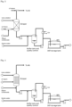
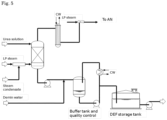
- Figs. 1 to 5 are all schematic drawings of equipment parts and process streams relating to embodiments of the invention
- the invention is based on the judicious insight to integrate the production of DEF with the production of liquid UAN fertilizer. This provides a process which is economically attractive, flexible to meet market demands, as well as environmentally and energy friendly due to the low number of equipment, zero emissions and the possibility to eliminate the waste water treatment section.
- the ammonia off-gas from urea production is sent to the AN section of a UAN plant, were the ammonia off gasses (which can be both liquid ammonia or (possibly diluted) gaseous ammonia), are neutralized with nitric acid so as to form AN, and accordingly blended to UAN. So the off-gasses are not sent to an outside environment, but remain in the process.
- a surprisingly low biuret concentration between 0.01 wt.% and 0.3 wt.% can be realized, even though the process involves producing urea by means of a stripping process.
- This low biuret content is believed to be achieved, inter alia , by the possibility to have a relatively small low Pressure (LP) recirculation section.
- LP recirculation (recovery) section of a urea stripping plant comprises a plurality of pieces of equipment, where in some areas high temperatures (such as around 135°C) are applied.
- the biuret content is prone to increase due to a longer residence time in this LP section.
- the possibility of eliminating equipment can be advantageous in reducing the residence time in the LP section (e.g. limited to a single rectifying column). This, in turn, provides the benefit of a possibly reduced biuret formation.
- the vapor from the recovery section is sent to the ammonium nitrate section.
- these vapors are condensed to form carbamate solution and subsequently returned to the HP synthesis section. This leads effectively to a recycle of water to the synthesis section.
- the urea is produced in equipment set up specifically for producing DEF in conjunction with UAN. Particularly, the urea is thereby produced using a submerged condenser/reactor (which is a urea reactor integrated with a submerged carbamate condenser), for example a pool reactor which is a horizontal submerged condenser/reactor. In this configuration no water/carbamate needs to be recycled to the urea synthesis. This is advantageous, as it makes the urea synthesis more efficient.
- various process settings can be adapted so as to minimize biuret production. E.g., by lowering the temperature in the stripper. This can have a considerable effect, since biuret is predominately formed in the outlet thereof. It is also conceivable to reduce the temperature and increase the pressure in the LP section, to lower the ammonia content and biuret formation.
- the urea production process described herein results in an aqueous stream. Rather than evaporating said stream, with the need for waste water treatment, the method of the invention provides for flexibly putting it to use. At least part of the stream is used in the production of UAN, by combining it with ammonium nitrate. At the same time, ammonia obtained from the separation step that results in said aqueous urea stream, is used in the production of ammonium nitrate.
- the amount of the aqueous urea stream used in the production of UAN is at least an amount corresponding to the amount of ammonium nitrate produced from the amount of ammonia separated off from the urea production.
- the urea ammonium nitrate solution comprises 29 wt.% to 38 wt.% of urea and 36 wt.% to 46 wt.% of ammonium nitrate.
- the part of the aqueous urea stream mixed with the ammonium nitrate solution is in an amount at least sufficient to provide the desired amount of ammonium nitrate obtainable by the amount of NH3 fed to the ammonium production unit.
- the UAN is produced by mixing aqueous urea with said aqueous ammonium nitrate so as to obtain a urea ammonium nitrate solution.
- the ammonium nitrate is produced by reacting ammonia and nitric acid.
- ammonium nitrate entails the acid-base reaction of ammonia with nitric acid: HNO3 + NH3 ⁇ NH4NO3
- Ammonia is normally used in its anhydrous form gas and the nitric acid is concentrated (typical concentration range: 40 to 80wt.%, such as about 60 wt.%). Via an exothermic reaction, the ammonium nitrate solution is readily formed, typically at a concentration of about 70% to 95%, such as 83% to 88%. Whilst in making solid ammonium nitrate products, such as prills or granules, the excess water is evaporated to an ammonium nitrate (AN) content of 95% to 99.9% concentration, this step can be dispensed with when making a urea ammonium nitrate solution. This UAN solution can be made by mixing an aqueous urea solution with the ammonium nitrate solution.
- the nitric acid used in the production of ammonium nitrate can be obtained as an external feed.
- the nitric acid is produced on site, as this is generally more attractive from an economical point of view than relying on transportation of nitric acid.
- the method of the invention is conducted in an integrated system for the production of urea and urea ammonium nitrate.
- This system comprises (i) a unit for the production of urea and (ii) a unit for the production of ammonium nitrate from ammonia and nitric acid.
- the unit for the production of urea comprises a urea synthesis section of the stripping type and, downstream thereof and in fluid communication therewith, a urea purification section suitable for separating off CO2 and NH3 from an aqueous urea solution comprising said CO2 and NH3.
- an outlet for NH3 from the purification section of the urea production unit is connected to an inlet for NH3 of the unit for the production of ammonium nitrate, i.e. so as to provide NH3 separated off from urea production as a feed to the production of ammonium nitrate.
- an outlet for an aqueous urea solution from the purification section of the urea production unit and an outlet for an aqueous ammonium nitrate solution from the unit for the production of ammonium nitrate are connected to a unit for mixing said aqueous urea solution and said aqueous ammonium nitrate solution.
- the invention pertains to such an integrated system for the production of urea and urea ammonium nitrate.
- the system of the invention may or may not also include a unit for the production of nitric acid.
- the main industrial method to produce nitric acid is from ammonia.
- anhydrous ammonia is oxidized to nitric oxide, in the presence of platinum or rhodium gauze catalyst at a high temperature of about 500 K and a pressure of 9 bar.
- Nitric oxide is then reacted with oxygen in air to form nitrogen dioxide.
- 2 NO (g) + O2 (g) ⁇ 2 NO2 (g) ( ⁇ H -114 kJ/mol)
- the nitrous oxide is cycled back for reoxidation.
- the last step can be carried out in air: 4 NO2 (g) + O2 (g) + 2 H2O (l) ⁇ 4 HNO3 (aq)
- the aqueous HNO3 obtained can be concentrated by distillation, generally up to about 68% by mass.
- An advantage in respect of the method and system of the present invention is that the nitric acid can be produced on a site that has an infrastructure for ammonia, as this is also used as a feed in the urea production.
- the system of the invention comprises a unit for the production of nitric acid
- this unit will generally be fed from external sources, and will have an outlet for nitric acid that is in fluid communication with an inlet for nitric acid of the unit for the production of ammonium nitrate.
- the urea production unit can be a conventional urea stripping plant, fully equipped with, downstream of the synthesis and recovery sections, also an evaporation section, a waste water treatment section, and a finishing section.
- a regular finishing section serving to form solid urea forms such as granules, pellets or prills
- DEF can be produced by diluting a part of the aqueous urea stream, obtained from separation of the urea reaction solution, with demineralized water. This results in a solution suitable for use in a unit for the reduction of NOx.
- the method of the invention can also be conducted so as to produce DEF in a solid form.
- a part of the aqueous urea stream, obtained from separation of the urea reaction solution, can be subjected to flash crystallization.
- This serves to form a solid urea powder which is suitable to be converted by dilution with demineralized water into a solution suitable for use in a unit for the reduction of NOx.
- This is of great benefit, as it is much more economically attractive to transport a solid urea powder, rather than having to transport DEF as a solution, which would require transporting a great amount of water as of the DEF production site.
- WO 2013/055219 For the production of a solid urea product by flash crystallization, reference is hereby made to WO 2013/055219 .
- the product disclosed therein is made by exerting a mechanical force on urea crystals. This step can be dispensed with for the production of powder that can be diluted to produce DEF.
- a free flowing urea powder can be obtained by obtaining an aqueous urea stream as mentioned above, subjecting said stream to flash crystallization at subatmospheric pressure, so as to obtain a solid crystallized urea containing product and a vapor comprising water and ammonia, wherein the solid crystallized urea product contains less than 0.2 wt.% water; and preferably packaging the solid crystallized urea product under conditions such that the water content in the packaged product is maintained below 0.2 wt.%.
- the flash crystallization is preferably conducted at a pressure below 15 kPa, more preferably from 1 to 10 kPa.
- the flashing is preferably conducted as dry flashing.
- Flashing can be done in a flashing device, such as a dry flasher.
- a dry flasher is characterized in that a liquid stream is converted by crystallization and evaporation into substantially a solid and a vapor.
- the process conditions are selected such that the amount of liquid remaining is substantially nil. This allows for a clean separation of the gas and the solids without substantial sticking and fouling.
- Another advantage of the dry flashing is that due to the absence of a slurry, no solid liquid separation such as a centrifuge, nor a re-melter is necessary. This allows a significantly simpler process scheme.
- Such a dry flasher is a vessel that operates preferably at a pressure in between 1 and 15 kPa and more preferably at a pressure in between 2 and 10 kPa.
- the urea solution is distributed by a liquid distributer.
- the particle size of the obtained solid urea product by adiabatic flashing is in the range of from 0.1 ⁇ m to 1000 ⁇ m, preferably of from 1 ⁇ m to 800 ⁇ m.
- the process described herein allows to produce a free flowing powder which can be packaged in bags (20 kg) or big bags (i.e., 500 kg or 1000 kg bags) which can be easily emptied on site to produce the DEF solution.
- the urea powder produced by the process has a very low quantity of biuret, typically less than 0.5%, preferably less than 0.4% which translates into less than 0.20% or less than 0.15% wt. in the final DEF solution. This means that the amount of active urea in the solution will be consequently higher at the same solids content.
- the biuret specification for the final DEF solution is max 0.3% wt. When prills are used to prepare the solution, the biuret content in the solution is typically between 0.27 and 0.36% wt.
- the solid crystallized urea product as obtained is packaged under conditions such that the water content in the packaged product is maintained below 0.2 wt.%.
- This low moisture content serves to ensure that the solid urea, which is hygroscopic by nature, remains a powder that is capable of being released from its package, and reconstituted to a solution.
- the water content in the packaged product is maintained below the aforementioned level until the product is to be used for preparing a solution.
- the powder obtained which has the required low moisture content, is packaged in a non water-permeable package (e.g. a container or a bag).
- a non water-permeable package e.g. a container or a bag.
- suitable packaging materials include high density polyethylene.
- Other plastics suitable for packaging hygroscopic materials are known in the art.
- the packing material may be non-porous and sealed.
- the package can consist of multi-layer material.
- the aforementioned powder is intended to be used for obtaining DEF by dissolving it in demineralized water. It will be understood that it can also be used in making UAN, should such be desired, e.g. in the event of a high demand of UAN. In the latter case, the powder can be dissolved also in regular tap water.
- the urea can synthesized by any suitable urea stripping process.
- Such processes are generally conducted in a stripping plant.
- the urea synthesis section of a stripping plant comprises at least one reactor, a stripper, and a condenser. These are generally operated at high pressure (HP), and in the art regularly referred to as a HP reactor, a HP stripper, and a HP carbamate condenser.
- HP high pressure
- the reactor, stripper, and condenser are in fluid communication with each other so as to form a urea synthesis loop. This does not require further elucidation to the skilled person.
- the reactor will produce an aqueous urea synthesis solution.
- Said solution will be subjected to stripping so as to produce a stripped solution and gaseous carbon dioxide and ammonia.
- the gaseous components will be condensed in the condenser, resulting in ammonium carbamate that is recirculated to the reactor.
- the condenser and the reactor can be integrated into a single apparatus.
- the stripped solution is subjected to further separation so as to obtain an aqueous urea stream, and a gas stream comprising CO2 and NH3.
- This separation generally takes place at a pressure lower than that in the synthesis section.
- Such lower pressure can be medium pressure (MP), low pressure (LP), or can involve both.
- MP and LP recirculation sections also referred to as recovery sections
- the prevailing pressures are generally of the order of 1-10 MPa, more typically 1-5 MPa for a MP section and 0.1 to 1 MPa, more typically 0.2 to 0.6 MPa, for a LP section.
- the plant of the invention and the plant modification methods of the invention are configured to accommodate conducting the process as described, by providing the appropriate MP and/or LP recirculation sections.
- a frequently used urea stripping process is the carbon dioxide stripping process as for example described in Ullmann's Encyclopedia of Industrial Chemistry, Vol. A27, 1996, pp 333-350 .
- the synthesis section is followed by one or more recovery sections.
- the synthesis section comprises a reactor, a stripper, a condenser and a scrubber in which the operating pressure is in between 12 and 18 MPa and preferably in between 13 and 16 MPa.
- the urea solution leaving the urea reactor is fed to a stripper in which a large amount of non-converted ammonia and carbon dioxide is separated from the aqueous urea solution.
- Such a stripper can be a shell and tube heat exchanger in which the urea solution is fed to the top part at the tube side and a carbon dioxide feed to the synthesis is added to the bottom part of the stripper. At the shell side, steam is added to heat the solution. The urea solution leaves the heat exchanger at the bottom part, while the vapor phase leaves the stripper at the top part. The vapor leaving said stripper contains ammonia, carbon dioxide and a small amount of water. Said vapor is condensed in a falling film type heat exchanger or a submerged type of condenser that can be a horizontal type or a vertical type. A horizontal type submerged heat exchanger is described in Ullmann's Encyclopedia of Industrial Chemistry, Vol.
- the heat released by the exothermic carbamate condensation reaction in said condenser is usually used to produce steam that is used in a downstream urea processing section for heating and concentrating the urea solution. Since a certain liquid residence time is created in a submerged type condenser, a part of the urea reaction takes already place in said condenser.
- the formed solution, containing condensed ammonia, carbon dioxide, water and urea together with the non-condensed ammonia, carbon dioxide and inert vapor is sent to the reactor. In the reactor the above mentioned reaction from carbamate to urea approaches the equilibrium.
- the ammonia to carbon dioxide molar ratio in the urea solution leaving the reactor is generally in between 2.5 and 4 mol/mol. It is also possible that the condenser and the reactor are combined in one piece of equipment. An example of this piece of equipment as described in Ullmann's Encyclopedia of Industrial Chemistry, Vol. A27, 1996, pp 333-350 .
- the formed urea solution leaving the urea reactor is supplied to the stripper and the inert vapor containing non-condensed ammonia and carbon dioxide is sent to a scrubbing section operating at a similar pressure as the reactor, or said vapor is sent directly to the ammonium nitrate section for neutralization (i..e. reaction with nitric acid so as to form ammonium nitrate).
- the ammonia and carbon dioxide is scrubbed from the inert vapor.
- the formed carbamate solution from the downstream recovery system is used as absorbent in that scrubbing section.
- the urea solution leaving the stripper in this synthesis section requires a urea concentration of at least 45 % by weight and preferably at least 50 % by weight to be treated in one single recovery system downstream the stripper.
- the recovery section comprises a heater, a liquid/gas separator and a condenser.
- the pressure in this recovery section is between 200 to 600 kPa.
- the heater of the recovery section the bulk of ammonia and carbon dioxide is separated from the urea and water phase by heating the urea solution. Usually steam is used as heating agent.
- the urea and water phase contains a small amount of dissolved ammonia and carbon dioxide that leaves the recovery section and is sent to a downstream urea processing section where the urea solution is concentrated by evaporating the water from said solution.
- the urea purification section comprises a rectification column containing a shell and tube heat exchanger and a gas/liquid separator wherein the aqueous urea solution is flowing through the tubes and steam is used on the shell side.
- a strip gas may also be used.
- the purpose of the purification section is to remove CO2 and ammonia from the aqueous urea solution produced in the synthesis section.
- the aqueous urea solution generally comprises urea, ammonium carbamate and unreacted CO2 and NH3.
- CO2 and NH3 in an aqueous urea solution are in equilibrium with ammonium carbamate.
- the formation of ammonium carbamate from CO2 and ammonia is an exothermic reaction.
- the removal of CO2 and ammonia from the aqueous solution may be effected by the addition of heat and/or the reduction of pressure optionally with the use of a stripping agent.
- the transition of CO2 and ammonia into the gas phase (evaporation) will shift the equilibrium of ammonium carbamate thereby promoting the dissociation of ammonium carbamate which in turn promotes the evaporation of CO2 and ammonia.
- the equipment used for the purification step is generally named by the major function it is assigned to do.
- the terms carbamate recovery system, dissociator, stripper, (pre-)evaporator are commonly used.
- the purification step may be carried out in the same type of equipment as is used in the recovery section of a standard urea plant.
- a rectifying column may be used.
- a shell and tube heat exchanger may be used with optionally a gas/liquid separator in the top of the vessel, or a separate gas/liquid separator.
- the purification step may be carried out in one or more steps.
- Other configurations and equipment are known to the skilled person.
- As an optional stripping agent CO2, ammonia or steam may be used.
- the DEF production unit applies for example (thermal) stripping with pressurized steam based on direct injection ( Fig. 3 ) or evaporation in a heat exchanger with pressurized steam by means of a shell and tube or plate heat exchanger ( Fig. 4 ) for product quality control on ammonia content at the outlet of the urea synthesis section.
- Such stripping is applied to remove excessive ammonia to comply with the DEF final product specification of 0.2wt% ammonia.
- the off-gasses from the thermal stripper are condensed and boosted with a steam ejector in at least one stage and to be combined with the regular synthesis off gasses send to the neutralizer in the ammonia nitrate section.
- these off gases are sent directly to the neutralizer (or after neutralizer) section in the ammonia nitrate production unit ( Figs. 3 and 5 ).
- the released ammonia is thereby used to neutralize the nitric acid in order to produce ammonium nitrate.
- the regular ammonia used for neutralization can be reduced by using the ammonia from the thermal stripper, reducing the virgin ammonia consumption of the ammonia nitrate plant.
- This arrangement can be applied with any urea synthesis arrangement. This method facilitates an efficient small dedicated DEF production or it can be aligned for large scale DEF production similar to the capacity of the urea synthesis.
- the invention can also be put to use in a method for the modernization of a pre-existing urea plant.
- a plant comprises a urea synthesis section and, downstream thereof and in fluid communication therewith, a urea purification section suitable for separating off CO2 and NH3 from an aqueous urea solution comprising said CO2 and NH3.
- the method comprising adding to the urea plant a unit for the production of ammonium nitrate from ammonia and nitric acid. Thereby an outlet for NH3 from the purification section of the urea plant is to be connected to an inlet for NH3 of the unit for the production of ammonium nitrate.
- an outlet for an aqueous urea solution from the purification section and an outlet for an aqueous ammonium nitrate solution from the unit for the production of ammonium nitrate are connected to a unit for mixing said aqueous urea solution and said aqueous ammonium nitrate solution.
- An advantage of the modernized plant is that it provides an additional possibility for using ammonia retrieved from the urea plant, allowing waste water treatment to be dispensed with.
- the invention pertains to building new urea plants, integrated with a production unit for ammonium nitrate.
- a great advantage, as discussed above, is that the new plant can be built without an evaporation section and a wastewater treatment section. It is noted that one can also build the new plant with these sections, if a greater versatility of different urea products (including solid urea forms, such as prills or granules) is desired in addition to DEF and UAN.
- a new urea production unit in an integrated system of the invention be built with a (flash) crystallization section, but - if desired - without a shaping section as would traditionally have been applied to produce solid urea forms such as prills or granules.
- NH3 and CO2 are fed to a urea synthesis zone. Shown is an embodiment in which NH3 is fed to the a urea synthesis reactor, and CO2 is fed to a high pressure stripper. The urea synthesis solution formed is led to a purification section. Therein non-reacted NH3 and CO2 are removed from the synthesis solution. Part of the resulting aqueous urea stream is used to obtain DEF, and part is used to be mixed with ammonium nitrate (not shown) so as to obtain UAN. The removed NH3, rather than being recirculated to urea synthesis, is sent to a unit (not shown) for the production of ammonium nitrate.
- Fig. 2 is similar to Fig. 1 .
- the aqueous urea solution is sent to a tank.
- the process choice can be made to use the aqueous urea in the production of UAN, in the production of DEF, or in both.
- This has the advantage of providing a buffer amount of the aqueous urea solution, which adds to the flexibility of the process.
- Fig. 3 shows DEF production by means of steam stripping with direct steam injection, and with off-gas sent to a unit for the production of ammonium nitrate, via LP steam injection.
- Fig. 4 shows DEF production with a thermal stripper.
- off-gas from the thermal stripper is sent to the AN neutralizer, rather than to a gas treatment and waste water section for cleaning.
- Fig. 5 shows a configuration similar to that of Fig. 4 , whereby use is made of a condenser and steam injector, as an alternative route to send the off-gasses to the AN section for neutralization. While the invention has been illustrated and described in detail in the drawings and foregoing description, such illustration and description are to be considered illustrative or exemplary and not restrictive; the invention is not limited to the disclosed embodiments.
- the invention includes a method for the integrated production of two different urea products.
- One is an aqueous urea solution suitable for use in NOx abatement (generally indicated as Diesel Exhaust Fluid - DEF).
- the other is a solution used as a fertilizer, viz. Urea Ammonium Nitrate (DAN).
- DAN Urea Ammonium Nitrate
- the production of DEF and UAN are integrated as follows: ammonia recovered from the production of urea is used as a feed to the production of ammonium nitrate. At least part of an aqueous urea stream from urea production, is mixed with ammonium nitrate so as to obtain UAN.
Landscapes
- Chemical & Material Sciences (AREA)
- Organic Chemistry (AREA)
- Chemical Kinetics & Catalysis (AREA)
- Inorganic Chemistry (AREA)
- Life Sciences & Earth Sciences (AREA)
- Pest Control & Pesticides (AREA)
- Organic Low-Molecular-Weight Compounds And Preparation Thereof (AREA)
- Fertilizers (AREA)
- Treating Waste Gases (AREA)
- Exhaust Gas After Treatment (AREA)
Applications Claiming Priority (3)
| Application Number | Priority Date | Filing Date | Title |
|---|---|---|---|
| EP15160826 | 2015-03-25 | ||
| EP16730029.2A EP3274297B1 (en) | 2015-03-25 | 2016-03-29 | Integrated production of urea for diesel exhaust fluid and urea ammonium nitrate |
| PCT/NL2016/050213 WO2016153354A1 (en) | 2015-03-25 | 2016-03-29 | Integrated production of urea for diesel exhaust fluid and urea ammonium nitrate |
Related Parent Applications (2)
| Application Number | Title | Priority Date | Filing Date |
|---|---|---|---|
| EP16730029.2A Division EP3274297B1 (en) | 2015-03-25 | 2016-03-29 | Integrated production of urea for diesel exhaust fluid and urea ammonium nitrate |
| EP16730029.2A Division-Into EP3274297B1 (en) | 2015-03-25 | 2016-03-29 | Integrated production of urea for diesel exhaust fluid and urea ammonium nitrate |
Publications (3)
| Publication Number | Publication Date |
|---|---|
| EP4015455A1 EP4015455A1 (en) | 2022-06-22 |
| EP4015455B1 true EP4015455B1 (en) | 2024-03-20 |
| EP4015455C0 EP4015455C0 (en) | 2024-03-20 |
Family
ID=52706096
Family Applications (2)
| Application Number | Title | Priority Date | Filing Date |
|---|---|---|---|
| EP22156578.1A Active EP4015455B1 (en) | 2015-03-25 | 2016-03-29 | Integrated production of urea for diesel exhaust fluid and urea ammonium nitrate |
| EP16730029.2A Active EP3274297B1 (en) | 2015-03-25 | 2016-03-29 | Integrated production of urea for diesel exhaust fluid and urea ammonium nitrate |
Family Applications After (1)
| Application Number | Title | Priority Date | Filing Date |
|---|---|---|---|
| EP16730029.2A Active EP3274297B1 (en) | 2015-03-25 | 2016-03-29 | Integrated production of urea for diesel exhaust fluid and urea ammonium nitrate |
Country Status (9)
| Country | Link |
|---|---|
| US (4) | US11083976B2 (pl) |
| EP (2) | EP4015455B1 (pl) |
| CN (1) | CN108137335B (pl) |
| EA (2) | EA036463B1 (pl) |
| HR (1) | HRP20220504T1 (pl) |
| HU (1) | HUE058722T2 (pl) |
| PL (1) | PL3274297T3 (pl) |
| SA (2) | SA517390004B1 (pl) |
| WO (1) | WO2016153354A1 (pl) |
Families Citing this family (9)
| Publication number | Priority date | Publication date | Assignee | Title |
|---|---|---|---|---|
| EP3323805A1 (en) * | 2016-11-18 | 2018-05-23 | Casale SA | A process for integrated production of urea and urea-ammonium nitrate |
| CA3082032C (en) | 2017-11-10 | 2021-10-26 | Stamicarbon B.V. | Urea production process and plant |
| CN113651674B (zh) * | 2020-05-12 | 2024-09-13 | 湖北远大富驰医药化工股份有限公司 | 用硫酸二甲酯蒸馏釜残液制备硫酸铵和甲醇的系统和方法 |
| CN116897076B (zh) | 2021-02-22 | 2024-08-27 | 斯塔米卡邦有限公司 | 具有并联mp单元的尿素生产方法和设施 |
| CN113426153B (zh) * | 2021-06-25 | 2024-06-21 | 中国成达工程有限公司 | 生产液体车用尿素及脱硝用尿素溶液的生产装置及方法 |
| EP4479376A1 (en) | 2022-02-15 | 2024-12-25 | Stamicarbon B.V. | Stripping-type urea plant for def production |
| US12240800B2 (en) | 2022-11-22 | 2025-03-04 | Stamicarbon B.V. | Multiproduct low biuret urea production |
| US12565622B2 (en) | 2023-09-08 | 2026-03-03 | Stamicarbon B.V. | Production of urea for diesel exhaust fluid |
| US12522563B2 (en) | 2023-09-08 | 2026-01-13 | Stamicarbon B.V. | Urea production with reduced urea losses |
Family Cites Families (11)
| Publication number | Priority date | Publication date | Assignee | Title |
|---|---|---|---|---|
| US2087325A (en) * | 1933-09-13 | 1937-07-20 | Solvay Process Co | Process for the production of urea and ammonium salts |
| NL165712C (nl) * | 1970-05-30 | 1981-05-15 | Stamicarbon | Werkwijze en inrichting voor het bij synthesedruk terug- winnen van ammoniak en kooldioxyde uit het spuigas van een ureumsynthese. |
| NL7612162A (nl) * | 1976-11-03 | 1978-05-08 | Unie Van Kunstmestfab Bv | Werkwijze voor de bereiding van een ureum- oplossing uit nh3 en co2. |
| US4174379A (en) * | 1978-04-13 | 1979-11-13 | Foster Wheeler Energy Corporation | Manufacture of ammonium nitrate |
| NL1028497C2 (nl) * | 2005-03-09 | 2006-09-12 | Dsm Ip Assets Bv | Werkwijze voor de bereiding van een ureum-bevattende waterige stroom. |
| EP1923383A1 (en) * | 2006-11-20 | 2008-05-21 | Urea Casale S.A. | Method for the modernization of a urea production plant |
| EP2153880A1 (en) * | 2008-07-31 | 2010-02-17 | Urea Casale S.A. | Process and plant for the production of a urea solution for use in SCR process for reduction of Nox |
| GEP20166499B (en) * | 2011-10-14 | 2016-06-27 | Stamicarbon | Method for urea final processing |
| EP2784062A1 (en) * | 2013-03-27 | 2014-10-01 | Urea Casale SA | Method for revamping a self-stripping urea plant |
| JP2016064991A (ja) * | 2014-09-22 | 2016-04-28 | 東洋エンジニアリング株式会社 | 尿素製造プロセスにおける高純度尿素水溶液の製造方法 |
| AR102834A1 (es) * | 2014-11-27 | 2017-03-29 | Stamicarbon | Método y planta para producir nitrato de amonio-urea (uan) |
-
2016
- 2016-03-29 EA EA201990748A patent/EA036463B1/ru not_active IP Right Cessation
- 2016-03-29 HR HRP20220504TT patent/HRP20220504T1/hr unknown
- 2016-03-29 US US15/560,460 patent/US11083976B2/en active Active
- 2016-03-29 WO PCT/NL2016/050213 patent/WO2016153354A1/en not_active Ceased
- 2016-03-29 EP EP22156578.1A patent/EP4015455B1/en active Active
- 2016-03-29 EP EP16730029.2A patent/EP3274297B1/en active Active
- 2016-03-29 PL PL16730029T patent/PL3274297T3/pl unknown
- 2016-03-29 HU HUE16730029A patent/HUE058722T2/hu unknown
- 2016-03-29 EA EA201792117A patent/EA037089B1/ru not_active IP Right Cessation
- 2016-03-29 CN CN201680018250.5A patent/CN108137335B/zh active Active
-
2017
- 2017-09-21 SA SA517390004A patent/SA517390004B1/ar unknown
- 2017-09-21 SA SA522431894A patent/SA522431894B1/ar unknown
-
2021
- 2021-07-07 US US17/368,924 patent/US12209061B2/en active Active
-
2024
- 2024-12-18 US US18/986,271 patent/US20250115547A1/en active Pending
-
2025
- 2025-04-09 US US19/174,513 patent/US20250236587A1/en active Pending
Also Published As
| Publication number | Publication date |
|---|---|
| HRP20220504T1 (hr) | 2022-06-24 |
| EP3274297B1 (en) | 2022-03-30 |
| US20210331086A1 (en) | 2021-10-28 |
| EP3274297A1 (en) | 2018-01-31 |
| EP4015455C0 (en) | 2024-03-20 |
| SA517390004B1 (ar) | 2022-08-03 |
| US20180071653A1 (en) | 2018-03-15 |
| CN108137335B (zh) | 2021-10-26 |
| EA201990748A1 (ru) | 2019-08-30 |
| PL3274297T3 (pl) | 2022-06-13 |
| EP4015455A1 (en) | 2022-06-22 |
| US11083976B2 (en) | 2021-08-10 |
| US12209061B2 (en) | 2025-01-28 |
| WO2016153354A9 (en) | 2016-11-10 |
| EA036463B1 (ru) | 2020-11-12 |
| US20250236587A1 (en) | 2025-07-24 |
| SA522431894B1 (ar) | 2023-03-01 |
| CN108137335A (zh) | 2018-06-08 |
| EA201792117A1 (ru) | 2018-02-28 |
| HUE058722T2 (hu) | 2022-09-28 |
| WO2016153354A1 (en) | 2016-09-29 |
| US20250115547A1 (en) | 2025-04-10 |
| EA037089B1 (ru) | 2021-02-04 |
| WO2016153354A8 (en) | 2018-03-08 |
Similar Documents
| Publication | Publication Date | Title |
|---|---|---|
| US12209061B2 (en) | Integrated production of urea for Diesel Exhaust Fluid and urea ammonium nitrate | |
| US10640428B2 (en) | Removal of urea and ammonia from exhaust gases | |
| US10954186B2 (en) | Urea ammonium nitrate production comprising condensation | |
| CN101006011B (zh) | 含尿素和硫酸铵的肥料生产方法 | |
| EP3169419B1 (en) | Method of making a urea product | |
| CA3166402C (en) | Ammonia removal from urea finishing | |
| US10654758B2 (en) | Urea ammonium nitrate production | |
| CN206705995U (zh) | 用于生产尿素和硝酸铵尿素的集成化系统 | |
| US12522563B2 (en) | Urea production with reduced urea losses |
Legal Events
| Date | Code | Title | Description |
|---|---|---|---|
| PUAI | Public reference made under article 153(3) epc to a published international application that has entered the european phase |
Free format text: ORIGINAL CODE: 0009012 |
|
| STAA | Information on the status of an ep patent application or granted ep patent |
Free format text: STATUS: REQUEST FOR EXAMINATION WAS MADE |
|
| 17P | Request for examination filed |
Effective date: 20220214 |
|
| AC | Divisional application: reference to earlier application |
Ref document number: 3274297 Country of ref document: EP Kind code of ref document: P |
|
| AK | Designated contracting states |
Kind code of ref document: A1 Designated state(s): AL AT BE BG CH CY CZ DE DK EE ES FI FR GB GR HR HU IE IS IT LI LT LU LV MC MK MT NL NO PL PT RO RS SE SI SK SM TR |
|
| P01 | Opt-out of the competence of the unified patent court (upc) registered |
Effective date: 20230516 |
|
| GRAP | Despatch of communication of intention to grant a patent |
Free format text: ORIGINAL CODE: EPIDOSNIGR1 |
|
| STAA | Information on the status of an ep patent application or granted ep patent |
Free format text: STATUS: GRANT OF PATENT IS INTENDED |
|
| RIC1 | Information provided on ipc code assigned before grant |
Ipc: C05G 5/23 20200101ALI20230913BHEP Ipc: C05C 1/00 20060101ALI20230913BHEP Ipc: B01J 19/00 20060101ALI20230913BHEP Ipc: B01D 3/00 20060101ALI20230913BHEP Ipc: C07C 275/02 20060101ALI20230913BHEP Ipc: C07C 273/02 20060101ALI20230913BHEP Ipc: C07C 273/04 20060101ALI20230913BHEP Ipc: C05C 9/00 20060101ALI20230913BHEP Ipc: C01C 1/18 20060101AFI20230913BHEP |
|
| INTG | Intention to grant announced |
Effective date: 20231006 |
|
| GRAS | Grant fee paid |
Free format text: ORIGINAL CODE: EPIDOSNIGR3 |
|
| GRAA | (expected) grant |
Free format text: ORIGINAL CODE: 0009210 |
|
| STAA | Information on the status of an ep patent application or granted ep patent |
Free format text: STATUS: THE PATENT HAS BEEN GRANTED |
|
| AC | Divisional application: reference to earlier application |
Ref document number: 3274297 Country of ref document: EP Kind code of ref document: P |
|
| AK | Designated contracting states |
Kind code of ref document: B1 Designated state(s): AL AT BE BG CH CY CZ DE DK EE ES FI FR GB GR HR HU IE IS IT LI LT LU LV MC MK MT NL NO PL PT RO RS SE SI SK SM TR |
|
| REG | Reference to a national code |
Ref country code: GB Ref legal event code: FG4D |
|
| REG | Reference to a national code |
Ref country code: CH Ref legal event code: EP |
|
| REG | Reference to a national code |
Ref country code: DE Ref legal event code: R096 Ref document number: 602016086508 Country of ref document: DE |
|
| REG | Reference to a national code |
Ref country code: IE Ref legal event code: FG4D |
|
| P04 | Withdrawal of opt-out of the competence of the unified patent court (upc) registered |
Effective date: 20240422 |
|
| U01 | Request for unitary effect filed |
Effective date: 20240419 |
|
| U07 | Unitary effect registered |
Designated state(s): AT BE BG DE DK EE FI FR IT LT LU LV MT NL PT SE SI Effective date: 20240425 |
|
| U20 | Renewal fee for the european patent with unitary effect paid |
Year of fee payment: 9 Effective date: 20240430 |
|
| PG25 | Lapsed in a contracting state [announced via postgrant information from national office to epo] |
Ref country code: GR Free format text: LAPSE BECAUSE OF FAILURE TO SUBMIT A TRANSLATION OF THE DESCRIPTION OR TO PAY THE FEE WITHIN THE PRESCRIBED TIME-LIMIT Effective date: 20240621 |
|
| PG25 | Lapsed in a contracting state [announced via postgrant information from national office to epo] |
Ref country code: HR Free format text: LAPSE BECAUSE OF FAILURE TO SUBMIT A TRANSLATION OF THE DESCRIPTION OR TO PAY THE FEE WITHIN THE PRESCRIBED TIME-LIMIT Effective date: 20240320 Ref country code: RS Free format text: LAPSE BECAUSE OF FAILURE TO SUBMIT A TRANSLATION OF THE DESCRIPTION OR TO PAY THE FEE WITHIN THE PRESCRIBED TIME-LIMIT Effective date: 20240620 |
|
| PG25 | Lapsed in a contracting state [announced via postgrant information from national office to epo] |
Ref country code: RS Free format text: LAPSE BECAUSE OF FAILURE TO SUBMIT A TRANSLATION OF THE DESCRIPTION OR TO PAY THE FEE WITHIN THE PRESCRIBED TIME-LIMIT Effective date: 20240620 Ref country code: NO Free format text: LAPSE BECAUSE OF FAILURE TO SUBMIT A TRANSLATION OF THE DESCRIPTION OR TO PAY THE FEE WITHIN THE PRESCRIBED TIME-LIMIT Effective date: 20240620 Ref country code: HR Free format text: LAPSE BECAUSE OF FAILURE TO SUBMIT A TRANSLATION OF THE DESCRIPTION OR TO PAY THE FEE WITHIN THE PRESCRIBED TIME-LIMIT Effective date: 20240320 Ref country code: GR Free format text: LAPSE BECAUSE OF FAILURE TO SUBMIT A TRANSLATION OF THE DESCRIPTION OR TO PAY THE FEE WITHIN THE PRESCRIBED TIME-LIMIT Effective date: 20240621 |
|
| PG25 | Lapsed in a contracting state [announced via postgrant information from national office to epo] |
Ref country code: IS Free format text: LAPSE BECAUSE OF FAILURE TO SUBMIT A TRANSLATION OF THE DESCRIPTION OR TO PAY THE FEE WITHIN THE PRESCRIBED TIME-LIMIT Effective date: 20240720 |
|
| PG25 | Lapsed in a contracting state [announced via postgrant information from national office to epo] |
Ref country code: SM Free format text: LAPSE BECAUSE OF FAILURE TO SUBMIT A TRANSLATION OF THE DESCRIPTION OR TO PAY THE FEE WITHIN THE PRESCRIBED TIME-LIMIT Effective date: 20240320 |
|
| PG25 | Lapsed in a contracting state [announced via postgrant information from national office to epo] |
Ref country code: ES Free format text: LAPSE BECAUSE OF FAILURE TO SUBMIT A TRANSLATION OF THE DESCRIPTION OR TO PAY THE FEE WITHIN THE PRESCRIBED TIME-LIMIT Effective date: 20240320 |
|
| PG25 | Lapsed in a contracting state [announced via postgrant information from national office to epo] |
Ref country code: PL Free format text: LAPSE BECAUSE OF FAILURE TO SUBMIT A TRANSLATION OF THE DESCRIPTION OR TO PAY THE FEE WITHIN THE PRESCRIBED TIME-LIMIT Effective date: 20240320 |
|
| PG25 | Lapsed in a contracting state [announced via postgrant information from national office to epo] |
Ref country code: SK Free format text: LAPSE BECAUSE OF FAILURE TO SUBMIT A TRANSLATION OF THE DESCRIPTION OR TO PAY THE FEE WITHIN THE PRESCRIBED TIME-LIMIT Effective date: 20240320 |
|
| PG25 | Lapsed in a contracting state [announced via postgrant information from national office to epo] |
Ref country code: SM Free format text: LAPSE BECAUSE OF FAILURE TO SUBMIT A TRANSLATION OF THE DESCRIPTION OR TO PAY THE FEE WITHIN THE PRESCRIBED TIME-LIMIT Effective date: 20240320 Ref country code: SK Free format text: LAPSE BECAUSE OF FAILURE TO SUBMIT A TRANSLATION OF THE DESCRIPTION OR TO PAY THE FEE WITHIN THE PRESCRIBED TIME-LIMIT Effective date: 20240320 Ref country code: PL Free format text: LAPSE BECAUSE OF FAILURE TO SUBMIT A TRANSLATION OF THE DESCRIPTION OR TO PAY THE FEE WITHIN THE PRESCRIBED TIME-LIMIT Effective date: 20240320 Ref country code: IS Free format text: LAPSE BECAUSE OF FAILURE TO SUBMIT A TRANSLATION OF THE DESCRIPTION OR TO PAY THE FEE WITHIN THE PRESCRIBED TIME-LIMIT Effective date: 20240720 Ref country code: ES Free format text: LAPSE BECAUSE OF FAILURE TO SUBMIT A TRANSLATION OF THE DESCRIPTION OR TO PAY THE FEE WITHIN THE PRESCRIBED TIME-LIMIT Effective date: 20240320 |
|
| REG | Reference to a national code |
Ref country code: DE Ref legal event code: R097 Ref document number: 602016086508 Country of ref document: DE |
|
| P05 | Withdrawal of opt-out of the competence of the unified patent court (upc) changed |
Free format text: CASE NUMBER: APP_21992/2024 Effective date: 20240425 |
|
| PG25 | Lapsed in a contracting state [announced via postgrant information from national office to epo] |
Ref country code: MC Free format text: LAPSE BECAUSE OF FAILURE TO SUBMIT A TRANSLATION OF THE DESCRIPTION OR TO PAY THE FEE WITHIN THE PRESCRIBED TIME-LIMIT Effective date: 20240320 |
|
| PG25 | Lapsed in a contracting state [announced via postgrant information from national office to epo] |
Ref country code: IE Free format text: LAPSE BECAUSE OF NON-PAYMENT OF DUE FEES Effective date: 20240329 |
|
| PLBE | No opposition filed within time limit |
Free format text: ORIGINAL CODE: 0009261 |
|
| STAA | Information on the status of an ep patent application or granted ep patent |
Free format text: STATUS: NO OPPOSITION FILED WITHIN TIME LIMIT |
|
| PG25 | Lapsed in a contracting state [announced via postgrant information from national office to epo] |
Ref country code: MC Free format text: LAPSE BECAUSE OF FAILURE TO SUBMIT A TRANSLATION OF THE DESCRIPTION OR TO PAY THE FEE WITHIN THE PRESCRIBED TIME-LIMIT Effective date: 20240320 Ref country code: IE Free format text: LAPSE BECAUSE OF NON-PAYMENT OF DUE FEES Effective date: 20240329 |
|
| 26N | No opposition filed |
Effective date: 20241223 |
|
| U20 | Renewal fee for the european patent with unitary effect paid |
Year of fee payment: 10 Effective date: 20250211 |
|
| PGFP | Annual fee paid to national office [announced via postgrant information from national office to epo] |
Ref country code: CH Payment date: 20250401 Year of fee payment: 10 |
|
| PG25 | Lapsed in a contracting state [announced via postgrant information from national office to epo] |
Ref country code: CY Free format text: LAPSE BECAUSE OF FAILURE TO SUBMIT A TRANSLATION OF THE DESCRIPTION OR TO PAY THE FEE WITHIN THE PRESCRIBED TIME-LIMIT; INVALID AB INITIO Effective date: 20160329 |
|
| PG25 | Lapsed in a contracting state [announced via postgrant information from national office to epo] |
Ref country code: HU Free format text: LAPSE BECAUSE OF FAILURE TO SUBMIT A TRANSLATION OF THE DESCRIPTION OR TO PAY THE FEE WITHIN THE PRESCRIBED TIME-LIMIT; INVALID AB INITIO Effective date: 20160329 |
|
| PG25 | Lapsed in a contracting state [announced via postgrant information from national office to epo] |
Ref country code: TR Free format text: LAPSE BECAUSE OF FAILURE TO SUBMIT A TRANSLATION OF THE DESCRIPTION OR TO PAY THE FEE WITHIN THE PRESCRIBED TIME-LIMIT Effective date: 20240320 |
|
| REG | Reference to a national code |
Ref country code: CH Ref legal event code: U11 Free format text: ST27 STATUS EVENT CODE: U-0-0-U10-U11 (AS PROVIDED BY THE NATIONAL OFFICE) Effective date: 20260401 |
|
| PGFP | Annual fee paid to national office [announced via postgrant information from national office to epo] |
Ref country code: GB Payment date: 20260324 Year of fee payment: 11 |
|
| PGFP | Annual fee paid to national office [announced via postgrant information from national office to epo] |
Ref country code: RO Payment date: 20260323 Year of fee payment: 11 |
|
| PGFP | Annual fee paid to national office [announced via postgrant information from national office to epo] |
Ref country code: CZ Payment date: 20260324 Year of fee payment: 11 |
|
| U20 | Renewal fee for the european patent with unitary effect paid |
Year of fee payment: 11 Effective date: 20260326 |