EP4013552B1 - Pneumatisches fördersystem zur schüttgutabscheidung - Google Patents
Pneumatisches fördersystem zur schüttgutabscheidung Download PDFInfo
- Publication number
- EP4013552B1 EP4013552B1 EP20775819.4A EP20775819A EP4013552B1 EP 4013552 B1 EP4013552 B1 EP 4013552B1 EP 20775819 A EP20775819 A EP 20775819A EP 4013552 B1 EP4013552 B1 EP 4013552B1
- Authority
- EP
- European Patent Office
- Prior art keywords
- vessel
- bulk material
- sifting device
- air
- separating
- Prior art date
- Legal status (The legal status is an assumption and is not a legal conclusion. Google has not performed a legal analysis and makes no representation as to the accuracy of the status listed.)
- Active
Links
Images


Classifications
-
- B—PERFORMING OPERATIONS; TRANSPORTING
- B07—SEPARATING SOLIDS FROM SOLIDS; SORTING
- B07B—SEPARATING SOLIDS FROM SOLIDS BY SIEVING, SCREENING, SIFTING OR BY USING GAS CURRENTS; SEPARATING BY OTHER DRY METHODS APPLICABLE TO BULK MATERIAL, e.g. LOOSE ARTICLES FIT TO BE HANDLED LIKE BULK MATERIAL
- B07B9/00—Combinations of apparatus for screening or sifting or for separating solids from solids using gas currents; General arrangement of plant, e.g. flow sheets
- B07B9/02—Combinations of similar or different apparatus for separating solids from solids using gas currents
-
- B—PERFORMING OPERATIONS; TRANSPORTING
- B65—CONVEYING; PACKING; STORING; HANDLING THIN OR FILAMENTARY MATERIAL
- B65G—TRANSPORT OR STORAGE DEVICES, e.g. CONVEYORS FOR LOADING OR TIPPING, SHOP CONVEYOR SYSTEMS OR PNEUMATIC TUBE CONVEYORS
- B65G53/00—Conveying materials in bulk through troughs, pipes or tubes by floating the materials or by flow of gas, liquid or foam
- B65G53/04—Conveying materials in bulk pneumatically through pipes or tubes; Air slides
- B65G53/16—Gas pressure systems operating with fluidisation of the materials
-
- B—PERFORMING OPERATIONS; TRANSPORTING
- B04—CENTRIFUGAL APPARATUS OR MACHINES FOR CARRYING-OUT PHYSICAL OR CHEMICAL PROCESSES
- B04B—CENTRIFUGES
- B04B5/00—Other centrifuges
- B04B5/10—Centrifuges combined with other apparatus, e.g. electrostatic separators; Sets or systems of several centrifuges
-
- B—PERFORMING OPERATIONS; TRANSPORTING
- B04—CENTRIFUGAL APPARATUS OR MACHINES FOR CARRYING-OUT PHYSICAL OR CHEMICAL PROCESSES
- B04C—APPARATUS USING FREE VORTEX FLOW, e.g. CYCLONES
- B04C9/00—Combinations with other devices, e.g. fans, expansion chambers, diffusors, water locks
-
- B—PERFORMING OPERATIONS; TRANSPORTING
- B07—SEPARATING SOLIDS FROM SOLIDS; SORTING
- B07B—SEPARATING SOLIDS FROM SOLIDS BY SIEVING, SCREENING, SIFTING OR BY USING GAS CURRENTS; SEPARATING BY OTHER DRY METHODS APPLICABLE TO BULK MATERIAL, e.g. LOOSE ARTICLES FIT TO BE HANDLED LIKE BULK MATERIAL
- B07B1/00—Sieving, screening, sifting, or sorting solid materials using networks, gratings, grids, or the like
- B07B1/18—Drum screens
- B07B1/20—Stationary drums with moving interior agitators
-
- B—PERFORMING OPERATIONS; TRANSPORTING
- B07—SEPARATING SOLIDS FROM SOLIDS; SORTING
- B07B—SEPARATING SOLIDS FROM SOLIDS BY SIEVING, SCREENING, SIFTING OR BY USING GAS CURRENTS; SEPARATING BY OTHER DRY METHODS APPLICABLE TO BULK MATERIAL, e.g. LOOSE ARTICLES FIT TO BE HANDLED LIKE BULK MATERIAL
- B07B1/00—Sieving, screening, sifting, or sorting solid materials using networks, gratings, grids, or the like
- B07B1/18—Drum screens
- B07B1/22—Revolving drums
- B07B1/24—Revolving drums with fixed or moving interior agitators
-
- B—PERFORMING OPERATIONS; TRANSPORTING
- B07—SEPARATING SOLIDS FROM SOLIDS; SORTING
- B07B—SEPARATING SOLIDS FROM SOLIDS BY SIEVING, SCREENING, SIFTING OR BY USING GAS CURRENTS; SEPARATING BY OTHER DRY METHODS APPLICABLE TO BULK MATERIAL, e.g. LOOSE ARTICLES FIT TO BE HANDLED LIKE BULK MATERIAL
- B07B1/00—Sieving, screening, sifting, or sorting solid materials using networks, gratings, grids, or the like
- B07B1/28—Moving screens not otherwise provided for, e.g. swinging, reciprocating, rocking, tilting or wobbling screens
-
- B—PERFORMING OPERATIONS; TRANSPORTING
- B07—SEPARATING SOLIDS FROM SOLIDS; SORTING
- B07B—SEPARATING SOLIDS FROM SOLIDS BY SIEVING, SCREENING, SIFTING OR BY USING GAS CURRENTS; SEPARATING BY OTHER DRY METHODS APPLICABLE TO BULK MATERIAL, e.g. LOOSE ARTICLES FIT TO BE HANDLED LIKE BULK MATERIAL
- B07B4/00—Separating solids from solids by subjecting their mixture to gas currents
- B07B4/08—Separating solids from solids by subjecting their mixture to gas currents while the mixtures are supported by sieves, screens, or like mechanical elements
-
- B—PERFORMING OPERATIONS; TRANSPORTING
- B65—CONVEYING; PACKING; STORING; HANDLING THIN OR FILAMENTARY MATERIAL
- B65G—TRANSPORT OR STORAGE DEVICES, e.g. CONVEYORS FOR LOADING OR TIPPING, SHOP CONVEYOR SYSTEMS OR PNEUMATIC TUBE CONVEYORS
- B65G53/00—Conveying materials in bulk through troughs, pipes or tubes by floating the materials or by flow of gas, liquid or foam
- B65G53/34—Details
- B65G53/36—Arrangements of containers
-
- B—PERFORMING OPERATIONS; TRANSPORTING
- B65—CONVEYING; PACKING; STORING; HANDLING THIN OR FILAMENTARY MATERIAL
- B65G—TRANSPORT OR STORAGE DEVICES, e.g. CONVEYORS FOR LOADING OR TIPPING, SHOP CONVEYOR SYSTEMS OR PNEUMATIC TUBE CONVEYORS
- B65G53/00—Conveying materials in bulk through troughs, pipes or tubes by floating the materials or by flow of gas, liquid or foam
- B65G53/34—Details
- B65G53/52—Adaptations of pipes or tubes
-
- B—PERFORMING OPERATIONS; TRANSPORTING
- B65—CONVEYING; PACKING; STORING; HANDLING THIN OR FILAMENTARY MATERIAL
- B65G—TRANSPORT OR STORAGE DEVICES, e.g. CONVEYORS FOR LOADING OR TIPPING, SHOP CONVEYOR SYSTEMS OR PNEUMATIC TUBE CONVEYORS
- B65G53/00—Conveying materials in bulk through troughs, pipes or tubes by floating the materials or by flow of gas, liquid or foam
- B65G53/34—Details
- B65G53/60—Devices for separating the materials from propellant gas
-
- B—PERFORMING OPERATIONS; TRANSPORTING
- B65—CONVEYING; PACKING; STORING; HANDLING THIN OR FILAMENTARY MATERIAL
- B65G—TRANSPORT OR STORAGE DEVICES, e.g. CONVEYORS FOR LOADING OR TIPPING, SHOP CONVEYOR SYSTEMS OR PNEUMATIC TUBE CONVEYORS
- B65G2201/00—Indexing codes relating to handling devices, e.g. conveyors, characterised by the type of product or load being conveyed or handled
- B65G2201/04—Bulk
- B65G2201/042—Granular material
-
- B—PERFORMING OPERATIONS; TRANSPORTING
- B65—CONVEYING; PACKING; STORING; HANDLING THIN OR FILAMENTARY MATERIAL
- B65G—TRANSPORT OR STORAGE DEVICES, e.g. CONVEYORS FOR LOADING OR TIPPING, SHOP CONVEYOR SYSTEMS OR PNEUMATIC TUBE CONVEYORS
- B65G53/00—Conveying materials in bulk through troughs, pipes or tubes by floating the materials or by flow of gas, liquid or foam
- B65G53/34—Details
- B65G53/40—Feeding or discharging devices
- B65G53/48—Screws or like rotary conveyors
Definitions
- the present invention relates to a pneumatic conveying system comprising a cyclonic feed apparatus.
- the present invention therefore relates to a pneumatic conveying system comprising a vessel (e.g. a cyclonic separator) in combination with a sifting device (e.g. a centrifugal device) which is capable of separating pneumatically conveyed material into oversize powder discharge (e.g. waste material) and fine powder discharge (e.g. valuable product material).
- a vessel e.g. a cyclonic separator
- a sifting device e.g. a centrifugal device
- Pneumatic conveying systems are used to transfer materials such as particulates, or powders etc. through enclosed pipelines. Air is used as the conveying mechanism, carrying the materials from an inlet to an outlet of the system by transmitting a propulsive force (i.e. a positive pressure) to the material.
- a propulsive force i.e. a positive pressure
- the pneumatic conveying apparatus requires a pressure differential between the inlet and outlet of the system. The pressure difference is usually provided by a pump on the inlet side of the system.
- materials are transferred from trucks into storage silos, via a sifter or sieve apparatus.
- the material is pumped via conveying air from the truck to the silo, via the sifter.
- a centrifugal sifter is a type of sifter, which is used to screen, separate, and remove material of different sizes at high rates of efficiency.
- the sifter contains a drum which is orientated substantially horizontally and comprises a shaft optionally with paddles attached to it, which rotates at high velocity.
- the material is fed into the drum from an inlet end, usually by a screw shaft. Whilst the material is inside the drum, it is forced to the interior walls of the drum by centrifugal force due to the rotation of the paddles attached to the shaft.
- the walls of the drum are lined with screens which are perforated with holes. The diameter of the holes determines the size of the material particulates which can pass through the sifter.
- the material travels along the drum, pushed along by the paddle assembly, until it has either been small enough to pass through the screens, or until it is passed along to the end of the drum to an outlet for oversized material. After the material has passed through the screens, it is gravity fed down a chute where it is reintroduced to the conveying pipeline which terminates inside the silo.
- the drum may also overfill, resulting in a lower sifting efficiency. Blocked perforations in the sifter may also cause blockages in the conveying system upstream.
- GB2116064A is a pressured, close loop, fluid bed combustion system with sizing means for separating fine from coarse grain material using a cyclone separator and a gravity and pressure fed screen.
- the present invention provides for apparatus for pneumatically conveying and separating bulk material and corresponding methods as claimed in the accompanying claims.
- the present invention therefore relates to a pneumatic conveying system comprising a cyclonic separator in combination with a cyclonic sifting apparatus which is capable of separating pneumatically conveyed material into oversize powder discharge (e.g. waste material) and fine powder discharge (e.g. valuable product material). This is discussed below in detail.
- oversize powder discharge e.g. waste material
- fine powder discharge e.g. valuable product material
- FIG. 1 is a representation of a cyclonic feed apparatus 10 according to the present invention.
- the cyclonic feed apparatus 10 is capable of receiving material from a vehicle 12.
- the vehicle 12 contains a transport silo 14 which feeds material to a vibration sifter 16.
- the vibration sifter 16 which is an optional feature, shakes the material to be conveyed and helps to prepare the material to be pneumatically conveyed by breaking down any large clumps of condensed material.
- This material is then fed to the cyclonic feed apparatus 10.
- Material then passes through the cyclonic feed apparatus 10 which is described in more detail below.
- the pneumatically conveyed material is then fed into a storage silo 18 via, for example, any suitable means such as a static sifter (e.g. a grid) 20.
- a static sifter e.g. a grid
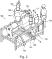
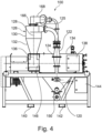
- Figures 2 to 4 are representations of a further cyclonic feed apparatus 100 according to the present invention.
- Figures 2 and 3 show material entering via the direction identified by arrow 'A' into the inlet feed 120.
- Figure 3 also shows the material exiting the cyclonic feed apparatus 100 via outlet feed 150 along the direction identified by arrow 'B'.
- Figures 2 to 4 show that the cyclonic feed apparatus 100 comprises an inlet feed 120.
- material may be received from the transport silo 104 and optionally the vibration sifter 16.
- Pneumatically conveyed material is then fed up through a substantially vertically located passageway 122, for example, in the form of a pipe.
- a substantially vertically located passageway 122 for example, in the form of a pipe.
- a coarse sieve 124 Located along the substantially vertical passageway 122 there is a coarse sieve 124.
- the conveyed material is then passed through inlet 125 into an upper section of a cyclone separator 126.
- the cyclone separator 126 may have a large volume such as over 50, 100 or 200 litres.
- the cyclone separator 126 is located substantially vertically along a substantially vertical axis 128 of the cyclonic feed apparatus 100.
- the cyclone separator 126 comprises two main sections.
- the first upper section 130 is substantially cylindrical in shape.
- the lower main section 132 is in a funnel form to feed material into the sifting device 134. It should be noted that the size and proportions of the cylindrical and funnel shapes may vary significantly from what is shown in the figures.
- the sifting device 134 is a centrifugal sifting device. This is described in more detail below.
- Figures 2 to 4 also show that the cyclonic feed apparatus 100 comprises a control panel 138 which is used to control the apparatus 100 and monitor the feed rate and operation of the apparatus 100.
- the cyclonic feed apparatus 100 also comprises elongate sections 140, 142 in the form of skids which allows a fork lift truck to easily lift and manoeuvre the cyclonic feed apparatus 100.
- pneumatic control device 144 which is used to control the pneumatic feed.
- Figures 2 to 4 also show that there is a conduit generally designated 160 which extends from below the sifting device to above the cyclone separator 126.
- the conduit 160 is in the form of a pipe extending from below a chute 162 located below the device 134.
- the conduit 160 comprises a substantially vertical section which may comprise a sieve 164.
- the conduit 160 then extends to above the cyclone separator 126 and is then connected to an upper section of the cyclone separator 126 via a section of pipe 168 and an upper located inlet 166.
- the function of the conduit 160 is to take the separated air from the cyclone separator 126 and reintroduce the air into the pneumatic conveying pipeline, via the outlet 150.
- This novel process of using the separated air to continue to convey the material after the sifting device 134 has many benefits.
- One such benefits is that there only needs to be one propulsive air source to convey material through the whole system.
- the air which is used to introduce the material into the cyclonic feed apparatus 100, is the same as the air used to convey the material out of the apparatus 100. This removes any need for additional energy sources within the apparatus to convey the air, thereby making the process more energy efficient.
- FIG. 5 represents part of a further cyclonic feed apparatus 200 according to the present invention.
- the cyclonic feed apparatus 200 comprises a cyclone separator 226 which comprises an upper section 228 and a lower section 232. There is also shown an inlet 225 into an upper section of the cyclone separator 226.
- Figure 5 shows a sifting device 234.
- the sifting device 234 is generally a substantially hollow cylindrical member which is located substantially horizontally.
- the sifting device 234 comprises a centrally and substantially horizontally mounted shaft 227 which is rotated during use resulting in material being forced to the outside surfaces 270, 272 of the sifting device 234 via centrifugal forces.
- outlying and/or protruding members such as paddles maybe located on the shaft 227 which assist in the material being stirred and/or rotated.
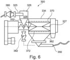
- Figure 6 represents a further cyclonic feed apparatus 300 according to the present invention.
- the cyclonic apparatus 300 shown in Figure 6 is very similar to the cyclonic apparatus 200 shown in Figure 5 .
- the cyclonic apparatus 300 comprises a cyclone separator 326 which comprises an upper section 328 and a lower section 332. There is also shown an inlet 325 into the upper section 328 of the cyclone separator 326. Of particular relevance, Figure 5 shows a sifting device 334.
- the sifting device 334 is generally a substantially hollow cylindrical member which is located substantially horizontally.
- a shaft 327 optionally comprising outlying and/or protruding members such as paddles is rotated during use resulting in material being forced to the outside surfaces 370, 372 of the sifting device 334 via centrifugal forces.
- the cyclonic feed apparatus 300 also comprises a coarse screen 380 which is used to filter material prior to entering the cyclone separator 326.
- the coarse screen 380 may have a screen range size of about 10- 30 mm or about 15 mm.
- a fine screen 382 which secures an air bypass.
- the fine screen 382 may have a screen range size of about 0.5 - 5 mm or about 2 mm.
- the air bypass with a cyclone provides that the pneumatically conveyed product has a possibility to be sieved because the airspeed and/or volume fluctuates due to a range of factors such as any one of or combination of the following: pneumatic conveying settings set by a truck driver; air supply; amount of product and a tanker silo on a vehicle; a variety of piping which may be used in different apparatus; and pressure drops anywhere in the systems.
- the cyclonic apparatus 200, 300 shown in Figures 5 and 6 may be used in the embodiments shown in Figures 1 to 4 .
- FIG. 7 is a representation of a partial sectional view of a further cyclonic feed apparatus 400 according to the present invention.
- the cyclonic feed apparatus 400 is shown in a partial sectional view which illustrates the travel of pneumatically conveyed material through the apparatus 400. This will now be discussed.
- powder feed material 401 is fed into a hopper 402.
- the powder feed material 401 may be fed from a transport silo 14 as shown in Figure 1 .
- the powder feed material 401 may be fed from any location or storage system.
- the powder feed material 401 is therefore gravity fed via the hopper 402 into a cyclone separator 404.
- the cyclone separator 404 will be similar to that shown in Figures 2 to 5 .
- the cyclone separator 404 is located substantially vertically.
- the cyclone separator 404 comprises an upper section through which material 401 is fed into from the hopper 402 and a lower section. inside the cyclone separator 404 a vortex of air and particulate material is formed where separation of the material 401 may occur. This is discussed in more detail below.
- the material exits the cyclone separator 404 along a substantially horizontal path into the sifting device generally designated 415.
- the material may be fed into the sifting device 415 via any suitable means such as a screw shaft.
- the sifting device 415 has an outer casing 410 which may contain an opening in the form of a door which may allow inspection and maintenance of the sifting device 415.
- Figure 7 also shows that there is a substantially centrally mounted shaft 412 which extends substantially horizontally through the sifting device 415.
- the substantially centrally mounted shaft 412 may comprise outlying and/or protruding members such as paddles which may assist in the stirring and/or rotation of the material within the sifting device.
- Figure 7 also shows that the sifting device 415 comprises a substantially horizontally mounted substantially cylindrical sieve 414 within which the powder feed material 401 is rotated and circulated at a speed of: about 100 - 1,000 rpm; about 200 - 750 rpm or about 500rpm. The speed varies for different sizes of machines and the diameters of rotation involved.
- the cylindrical sieve 414 comprises a mesh-like structure with a series of small apertures.
- the apertures in the mesh-like structure may have a cross-sectional diameter of any of the following: about 50 mm; about 100 mm; about 200 mm; about 300 mm; about 380 mm; about 400 mm; about 500 mm; about 600 mm; about 700 mm; about 800 mm; about 900 mm; about 1,000 mm; or about 2,000 mm.
- the apertures may have a cross-sectional diameter of any of the following: about 100- 1,000 mm; about 200 - 750 mm; about 300 - 500mm; or about 300 - 400 mm.
- the mesh-like structure allows fine particulate material 422 to pass through the cylindrical sieve 414 and exit as shown as a fine powder discharge 422 through an outlet 430 located below the sifting device 415.
- the cross-sectional size of the fine powder discharge 422 particles is selected from any of the following: about 50 microns to about 50 mm; about 100 microns to 10 mm; or about 200 microns to 10 mm.
- the fine powder discharge 422 is valuable product material. It has been found that the present invention allows the capture of a much greater percentage of fine powder discharge material 422 in comparison to prior art systems. This is because fewer 'clumps' of material enter into the sifting device 415, due to the presence of the cyclone separator 404.
- the cyclone separator 404 maintains an almost constant material mass flow rate at its outlet, before being fed into the sifting device 415.
- the constant mass flow rate received by the sifting device 415 prevents the sifting device 415 becoming clogged up, and becoming less efficient.
- Larger particulate material e.g. waste material
- the size of the oversize powder discharge 420 particles is larger than the apertures or holes in the cylindrical sieve 414.
- Figure 7 also shows that the cyclonic feed apparatus 400 comprises a release assembly 416 which may in some embodiments be a quick release basket assembly. There is also a motor 408 which is used to provide rotation to the shaft 412 located in the sifting device 415.
- a release assembly 416 which may in some embodiments be a quick release basket assembly.
- a motor 408 which is used to provide rotation to the shaft 412 located in the sifting device 415.
- an inspection door 418 which may be hinged and quick release to allow easy and quick access.
- a chute 440 which collects the fine powder material which exits as a fine powder discharge 422.
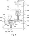
- FIG 8 is a further cyclonic feed apparatus according to the present invention generally designated 500.
- the cyclonic feed apparatus 500 is similar to the apparatus previously described in Figures 1 to 7 .
- the cyclonic feed apparatus 500 comprises a cyclone separator 526 which is located substantially vertically.
- the cyclone separator 526 comprises an upper section 528 which is substantially cylindrical and a lower section 532 which funnels material down into a sifting device 534.
- particulate material enters via an inlet 512 into the upper section 528 of the cyclone separator 526.
- inlet 512 may be more than one, two, three or a plurality of inlets feeding particulate material into the cyclone separator 526.
- FIG. 8 A preferred embodiment is shown in Figure 8 where the inlet 512 passes the particulate material in a substantially tangential direction into the cyclone separator 526 which is substantially cylindrical in shape.
- the tangential direction is tangential to a central axis extending through the centre of the cyclone separator 526.
- the tangential direction of the particulate material has been found to be preferred but other directions of input for the material may be used.
- the material may be fed at a velocity 'V' into the cyclone separator 526 at a range of: about 5 m/s to 100 m/s; about 20 m/s to about 60m/s or about 8 m/s to 50 m/s.
- the material may be fed at a velocity 'V' into the cyclone separator 526 at a range of: about 5 m/s; about 10 m/s; about 20 m/s; about 30 m/s; about 40 m/s; about 50 m/s; about 60 m/s; about 60 m/s; about 70 m/s; about 80 m/s; about 90 m/s or about 100 m/s.
- the particulate material 528 is then caused to rotate in a cyclonic vortex due to the rotation of air within the cyclonic separator 526. They pneumatically conveyed air and particulate material fed into the inlet 512 causes the cyclonic vortex rotation of the air and particulate material within the cyclone separator 526. During the cyclonic motion of the particulate material the particulate material is forced to the outer surfaces of the cyclone separator 526 in a vortex-like manner.
- the particulate material then passes through an outlet 536 of the cyclone separator 526 and into a substantially horizontally located channel 538. Via the channel 538 material is then fed via, for example, a screw shaft, and pneumatically conveyed into the sifter device 534.
- the screw shaft may be driven by a motor.
- the sifter device 534 comprises a substantially longitudinally oriented cylindrical hollow sieve 540.
- the cylindrical sieve 540 may be in the form of a drum.
- the cylindrical sieve 540 comprises a mesh-like structure with a series of small apertures with the cross-sectional diameter.
- the cylindrical sieve 540 may comprise and be lined with a series of screens which are perforated with holes.
- the apertures in the mesh-like structure have a cross-sectional diameter of any of the following: about 50 mm; about 100 mm; about 200 mm; about 300 mm; about 380 mm; about 400 mm; about 500 mm; about 600 mm; about 700 mm; about 800 mm; about 900 mm; about 1,000 mm; or about 2,000 mm.
- the apertures have a cross-sectional diameter of any of the following: about 100 - 1,000 mm; about 200 - 750 mm; about 300 - 500mm; or about 300 - 400 mm.
- a screw conveyor 537 is shown transferring the material from the outlet 536 of the cyclone separator 526 along and into the sifter device 534.
- any suitable type of device may be used to assist the transfer of the material into the sifter device 534.
- a shaft 535 which contains a series of outlying and/or protruding members (e.g. paddles) 539 which are used to assist in the stirring and/or rotation of the material.
- the shaft 535 is therefore rotated and driven by the motor M whereupon the outlying and/or protruding members (e.g. paddles) 539 force the material outwards to the cylindrical sieve 540. This allows the separation of the material to occur under centrifugal forces into smaller and larger particulate material.
- chute 562 Sifted material exits through outlet 544.
- the mesh-like structure allows fine particulate material 542 to pass through the cylindrical sieve 534 and exit as shown as a fine powder discharge 544 out through an outlet 546 from the bottom of the cyclonic feed apparatus 500.
- the size of the fine powder discharge 544 particles is smaller than the size of the apertures in the mesh-like structure.
- Larger sized particulate material is retained within the cylindrical sieve 540 and exits through an outlet 550 as an oversize powder discharge.
- the size of the oversize powder discharge particles is larger than the size of the apertures in the mesh-like structure in the cylindrical sieve 540.
- Figure 8 also shows that there is a conduit (or passageway) 570 connecting the upper section 528 of the cyclonic separator 526 and the outlet 546 from the bottom of the cyclonic feed apparatus 500.
- a conduit (or passageway) 570 connecting the upper section 528 of the cyclonic separator 526 and the outlet 546 from the bottom of the cyclonic feed apparatus 500.
- the additionally conveyed pneumatic air along the conduit (or passageway) 570 may therefore collect and assist in transfer of the fine powder discharge 544.
- This is a specific advantage of the present invention in that there is a highly efficient use of the pneumatically conveyed air in the whole system.
- Material exiting from the outlet 546 at the bottom of the cyclonic feed apparatus 500 may then be collected and continued to be conveyed.
- Figure 9 is an expanded cross-sectional view of the cyclone separator 526 shown in Figure 8 .
- the particulate material 580 is shown to be thrown against the sidewalls of the upper section 528 of the cyclone separator 526 and then funnelled down along into the lower section 532 of the cyclone separator 526.
- Pneumatically fed air and material is tangentially fed via inlet 512 into the cyclone separator 526 at a sufficient rate to cause a vortex within the cyclone separator 526 to allow separation of material to start to occur.
- Figure 9 clearly shows that the cyclone (i.e. vortex) of air builds a rotating mass of material 580 against the sidewalls of the cyclonic separator 526.
- the material being formed against the sidewalls of the cyclonic separator 526 therefore forms, for example, a tubular shape.
- a specific advantage of the rotating mass of material 580 in the cyclone separator 526 is that the rotating mass of particulate material 580 has the ability to absorb sudden increases in material feed by adjusting the thickness dimension 'T' and density of the particulate material 580 being forced against the inner surfaces of the cyclone separator 526.
- the dimension 'T' showing the thickness of the tubular shape of particulate material circulating in a cyclone form is shown in Figure 9 .
- the velocity 'V' of the air and particulate material being fed into the cyclone separator 526 has to be sufficiently high to cause the particulate material to spin and form, for example, a substantially tubular shape.
- the required velocity 'V' of the air and particulate material being fed into the cyclone separator 526 changes with different materials but is typically in the range of: 5 m/s to 100 m/s; or 8 m/s to 50 m/s. As described in reference to Figure 8 , after the air has created a cyclone, it exits up through the centre of the cyclone separator 526 via the outlet 572.
- the apparatus described in the present invention have a number of technical advantages and benefits.
- the centrifugal sifters described in the present invention use a fine aperture screen to separate material into oversize powder discharge (e.g. waste product) and fine powder discharge (e.g. desired product).
- a "large” aperture screen can tolerate variations in instantaneous mass flow rate and airflow which occurs inherently in pneumatic conveying systems.
- the market trend is to use "finer" apertures two separate waste and product. The finer the aperture the less tolerant the screen is of the air and variations of air entering the feeding by pneumatic conveying.
- the present inventors have found that it is highly advantageous in such situations to use a cyclonic separator (i.e.
- a cyclonic centrifuge to smooth out the mass flow by damping the fluctuations in the cyclone body and also by separating the air from the material using the cyclone. It has been found that the combination of these two aspects (i.e. the cyclonic separator and the centrifugal sifter) provides a more stable system with reduced mass flow fluctuations. The flow of separated material and air is then presented to the fine aperture screen of the cyclonic sifter. This allows the centrifugal sifter to pass a larger amount of material than would otherwise be the case in the short residence time the material has in the centrifugal sifter. This results in less waste material (i.e. oversize powder discharge) and more product (i.e. fine powder discharge) being separated even if a finer aperture screen is used in the centrifugal sifter. This is a significant advantage over prior art systems.
- the present inventors have therefore found it to be technically advantageous to take a cyclone which is usually used to separate air and material at atmospheric pressure and use it at positive pressure (i.e. above atmospheric pressure) in order to store material in order to dampen the constant variation in mass flow inherent to pneumatic conveying. It has also been found that by using the cyclone at positive pressure provides the further advantage in that positively pressurised air can be reused to pneumatically convey the "product" from the centrifugal sifter to the downstream process. This is shown in Figure 8 using the conduit 570. This provides the additional benefit of avoid ing the need for a second pneumatic conveying power source that would otherwise be required. There are clear environmental and commercial benefits in only having the requirement for one pneumatic conveying power source.
- any suitable type of cyclonic separator and cyclonic sifter may be used.
- any suitable type of pipework may be used to connect the different parts of the apparatus.
- the apparatus of the present invention may also be used to convey any suitable type of particulate, granular and/or powder bulk material.
Landscapes
- Engineering & Computer Science (AREA)
- Mechanical Engineering (AREA)
- Cyclones (AREA)
- Combined Means For Separation Of Solids (AREA)
- Air Transport Of Granular Materials (AREA)
Claims (15)
- Einrichtung (500) zum pneumatischen Fördern und Abscheiden von Schüttgutmaterial, umfassend:ein Gefäß (526) zum Aufnehmen und Abscheiden von Gas (z. B. Luft) und Schüttgutmaterial;mindestens einen auf dem Gefäß (526) angeordneten Materialeinlass (512) zum Einbringen von Gas (z. B. Luft) und Schüttgutmaterial in das Gefäß (526) und Bilden eines Zyklons, der das Gas (z. B. die Luft) und das Schüttgutmaterial in dem Gefäß (526) abscheidet;eine Sichtvorrichtung (534) zum Aufnehmen des Schüttgutmaterials von dem Gefäß (526), wobei Schüttgutmaterial in mindestens zwei oder mehrere unterschiedliche Pulverausstöße abgeschieden wird; undwobei eine Leitung (570) das Gefäß (526) und einen Auslass (546) verbindet, der unterhalb der Sichtvorrichtung (534) angeordnet ist, der ermöglicht, dass ein Luftstrom von dem Gefäß (526) entlang der Leitung (570) zu dem Auslass (546) wandert, der das Auffangen und den Transfer eines Feinpulverausstoßes (544) unterstützt,dadurch gekennzeichnet, dass Schüttgutmaterial über Zentrifugalkräfte in die mindestens zwei oder mehreren unterschiedlichen Pulverausstöße abgeschieden wird.
- Einrichtung (500) zum pneumatischen Fördern und Abscheiden von Schüttgutmaterial nach Anspruch 1, wobei das Gefäß (526) ein Zyklonabscheider ist und die Sichtvorrichtung (534) eine Zentrifugalsichtvorrichtung ist, die in der Lage ist, pneumatisch befördertes Material in einen Übergrößenpulverausstoß (z. B. Abfallmaterial) aus einem ersten Sichterauslass und einen Feinpulverausstoß (544) (z. B. werthaltiges Produktmaterial) aus einem zweiten Sichterauslass abzuscheiden, und/oder wobei das Gefäß (526) im Wesentlichen eine zylindrische Form mit einem konisch geformten unteren Abschnitt (532) aufweist, der dazu verwendet wird, Material trichterartig zu der Sichtvorrichtung (534) zu leiten.
- Einrichtung (500) zum pneumatischen Fördern und Abscheiden von Schüttgutmaterial nach einem der vorhergehenden Ansprüche, wobei das Gefäß (526) im Gebrauch im Wesentlichen vertikal angeordnet ist und eine im Wesentlichen längsverlaufende Achse aufweist, die sich vertikal durch das Gefäß (526) erstreckt, wodurch ermöglicht wird, dass das abgeschiedene Schüttgutmaterial mittels Schwerkraft zu der Sichtvorrichtung (534) gespeist wird, und/oder wobei das Gefäß (526) zwei oder eine Mehrzahl von Materialgefäßeinlässen zum Einbringen von Luft und Schüttgutmaterial in das Gefäß (526) umfasst.
- Einrichtung (500) zum pneumatischen Fördern und Abscheiden von Schüttgutmaterial nach einem der vorhergehenden Ansprüche, wobei der mindestens eine, die zwei oder die Mehrzahl von Materialgefäßeinlässen auf dem Gefäß (526) im Wesentlichen tangential zu der längsverlaufenden Achse des Gefäßes (526) angeordnet sind, wodurch die Bildung eines Zyklons aus Luft und Schüttgutmaterial (d. h. eines Wirbels) in dem Gefäß (526) erleichtert wird, und/oder wobei das Gefäß (526) mindestens einen oder mehrere Luft- und/oder Materialauslässe umfasst, die abgeschiedene Luft und abgeschiedenes Material zu der Sichtvorrichtung (534) speisen.
- Einrichtung (500) zum pneumatischen Fördern und Abscheiden von Schüttgutmaterial nach einem der vorhergehenden Ansprüche, wobei im Gebrauch ein positiver Druckgradient (d. h. über Atmosphärendruck) von dem mindestens einen Gefäßeinlass (512) zu einem pneumatischen Förderauslass aufrechterhalten wird, der auf der Sichtvorrichtung (534) angeordnet ist.
- Einrichtung (500) zum pneumatischen Fördern und Abscheiden von Schüttgutmaterial nach einem der vorhergehenden Ansprüche, wobei das Gefäß (526) mindestens einen oder mehrere Gas- und/oder Materialauslässe umfasst, die im Wesentlichen mit der längsverlaufenden Achse des Gefäßes (526) ausgerichtet sind, und/oder wobei die Sichtvorrichtung (534) einen Materialeinlass zum Aufnehmen von Luft und/oder Material aus dem Gefäß (526) über zum Beispiel einen Materialauslass aus dem Gefäß (526) umfasst.
- Einrichtung (500) zum pneumatischen Fördern und Abscheiden von Schüttgutmaterial nach einem der vorhergehenden Ansprüche, wobei die Sichtvorrichtung (534) die Form einer zylindrischen Kammer aufweist, die im Wesentlichen horizontal positioniert ist, und/oder wobei die Sichtvorrichtung (534) mit einer Reihe von Perforationen ausgekleidet ist, beispielsweise in Form einer perforierten Schicht.
- Einrichtung (500) zum pneumatischen Fördern und Abscheiden von Schüttgutmaterial nach einem der vorhergehenden Ansprüche, wobei die Sichtvorrichtung (534) eine perforierte Trommel umfasst, und/oder wobei die Sichtvorrichtung (534) ein im Wesentlichen horizontal angebrachtes im Wesentlichen zylindrisches Sieb (z. B. eine Trommel) umfasst, in dem das Pulverspeisematerial bei einer Drehzahl von etwa 100-1.000 U/min; etwa 200-750 U/min oder etwa 500 U/min gedreht und zirkuliert wird.
- Einrichtung (500) zum pneumatischen Fördern und Abscheiden von Schüttgutmaterial nach einem der vorhergehenden Ansprüche, wobei die Sichtvorrichtung (534) die Form eines zylindrischen Siebs aufweist, das eine netzartige Struktur mit einer Reihe von kleinen Öffnungen umfasst, wobei die kleinen Öffnungen einen Querschnittsdurchmesser von 100-1.000 mm aufweisen, und
wobei Material mit größeren Partikeln (z. B. Abfallmaterial) in dem zylindrischen Sieb zurückgehalten wird und durch einen Auslass als ein Übergrößenpulverausstoß austritt, und Material mit feinen Partikeln durch das zylindrische Sieb als ein Feinpulverausstoß (z. B. werthaltiges Produktmaterial) passiert und durch einen Auslass als ein Feinpulverausstoß austritt. - Einrichtung (500) zum pneumatischen Fördern und Abscheiden von Schüttgutmaterial nach einem der Ansprüche 8 oder 9, wobei die Sichtvorrichtung (534) eine Welle mit außenliegenden und/oder hervorstehenden Elementen (z. B. Schaufeln) umfasst, die auf der Welle angeordnet sind, die bei Drehung zum Rühren und/oder Drehen des Materials in der Sichtvorrichtung verwendet werden, woraufhin unter Zentrifugalkräften das gerührte und/oder gedrehte Material gegen die perforierte Schicht oder das im Wesentlichen zylindrische Sieb in Form einer perforierten Trommel oder die netzartige Struktur gedrückt wird, was ermöglicht, dass eine Abscheidung des Schüttgutmaterials in Material mit größeren und kleineren Partikeln erfolgt, und/oder
wobei durch Drehen des Materials in der Sichtvorrichtung (534) bewirkt wird, dass zumindest ein Teil des Schüttgutmaterials durch Perforationen und/oder Öffnungen in der Sichtvorrichtung (534) passiert; und wobei Material, das durch Perforationen der Sichtvorrichtung (534) passiert, aus der Sichtvorrichtung (534) über einen ersten Materialauslass als Feinpulverausstoß austritt und werthaltiges Produktmaterial ist, und Material mit größer dimensionierten Partikeln, das nicht in der Lage ist, durch die Perforationen in der Sichtvorrichtung (534) zu passieren, die Sichtvorrichtung (534) über einen zweiten Materialauslass als Übergrößenpulverausstoß verlässt und Abfallmaterial ist. - Einrichtung (500) zum pneumatischen Fördern und Abscheiden von Schüttgutmaterial nach einem der vorhergehenden Ansprüche, wobei die Einrichtung zudem einen Trichter (402) zum Speisen von Schüttgutmaterial aus einem Transportsilo oder einem anderen Speichersystem in die Einrichtung umfasst, und/oder wobei die Sichtvorrichtung (534) einen Antrieb zum Drehen eines zylindrischen Siebs umfasst, das in der Sichtvorrichtung (534) angeordnet ist.
- Verfahren zum Fördern und Abscheiden von Schüttgutmaterial, umfassend:Bereitstellen eines Gefäßes (526) zum Aufnehmen und Abscheiden von Gas (z. B. Luft) und Schüttgutmaterial,Bereitstellen mindestens eines auf dem Gefäß (526) angeordneten Materialeinlasses (512) zum Einbringen von Luft und Schüttgutmaterial in das Gefäß (526) und Bilden eines Zyklons, der das Gas (z. B. die Luft) und das Schüttgutmaterial in dem Gefäß (526) abscheidet; undBereitstellen einer Sichtvorrichtung (534) zum Aufnehmen von Schüttgutmaterial aus dem Gefäß (524), wobei die Sichtvorrichtung (534) das Schüttgutmaterial in mindestens zwei oder mehrere unterschiedliche Pulverausstöße abscheidet;wobei eine Leitung (570) das Gefäß (526) und einen Auslass (546) verbindet, der unterhalb der Sichtvorrichtung (534) angeordnet ist, der ermöglicht, dass ein Luftstrom von dem Gefäß (526) entlang der Leitung (570) zu dem Auslass (546) wandert, der das Auffangen und den Transfer eines Feinpulverausstoßes (544) unterstützt,dadurch gekennzeichnet, dass Schüttgutmaterial über Zentrifugalkräfte in die mindestens zwei oder mehreren unterschiedlichen Pulverausstöße abgeschieden wird.
- Verfahren zum Fördern und Abscheiden von Schüttgutmaterial nach Anspruch 12, wobei eine Einrichtung (500), die zum Fördern und Abscheiden des Schüttgutmaterials verwendet wird, wie in einem der Ansprüche 1 bis 11 definiert ist, und wobei im Gebrauch ein positiver Druckgradient (d. h. über Atmosphärendruck) von dem mindestens einen Gefäßeinlass (512) zu einem oder einer Mehrzahl von pneumatischen Förderauslässen aufrechterhalten wird, die auf der Sichtvorrichtung (534) angeordnet sind.
- Verfahren zum Fördern und Abscheiden von Schüttgutmaterial nach einem der Ansprüche 12 oder 13, wobei im Gebrauch das Material in den mindestens einen Gefäßeinlass (512) bei einer derartigen Drehzahl gespeist wird, dass das Material in dem Gefäß (526) eine zyklonartige röhrenförmige Auslegung annimmt, und wobei das Material, während seine zyklonartige röhrenförmige Auslegung aufrechterhalten wird, von mindestens einem Gefäßmaterialauslass zu der Sichtvorrichtung (534) passiert, was die Abscheidung der Luft und des Schüttgutmaterials erleichtert.
- Verfahren zum Fördern und Abscheiden von Schüttgutmaterial nach einem der Ansprüche 12 bis 14, wobei das Material bei einer Geschwindigkeit 'V' im Wesentlichen tangential in das Gefäß (z. B. Zyklonabscheider) in einem Bereich von etwa 5 m/s bis 100 m/s oder etwa 8 m/s bis 50 m/s gespeist wird, und/oder wobei bewirkt wird, dass sich Schüttgutmaterial aufgrund der Drehung von Luft in dem Gefäß (526) in einem zyklonartigen Wirbel dreht, und während der zyklonartigen Bewegung des Partikelmaterials das Partikelmaterial an die Außenflächen des Gefäßes (526) in einer wirbelartigen Weise gedrückt wird und wobei während des Gebrauchs Partikelmaterial gegen die Seitenwände eines oberen Abschnitts des Gefäßes (526) geschleudert und dann trichterartig nach unten entlang in einen unteren Abschnitt (532) des Gefäßes (526) geleitet wird, wobei der Zyklon (d. h. der Wirbel) von Luft dadurch eine sich drehende Masse aus Material gegen die Seitenwände des Gefäßes (526) aufbaut, die die Fähigkeit hat, plötzliche Zunahmen und/oder Abnahmen bei einer Materialeinspeisung durch Anpassen der Dickenabmessung 'T' und Dichte des Partikelmaterials, das gegen die Innenflächen des Gefäßes (526) gedrückt wird, zu absorbieren.
Applications Claiming Priority (3)
| Application Number | Priority Date | Filing Date | Title |
|---|---|---|---|
| GBGB1911632.6A GB201911632D0 (en) | 2019-08-14 | 2019-08-14 | Truck unloading Sifter |
| GB201914172A GB201914172D0 (en) | 2019-10-01 | 2019-10-01 | Improvements in or relating to sieving |
| PCT/EP2020/072882 WO2021028575A1 (en) | 2019-08-14 | 2020-08-14 | Pneumatic conveying system for separating bulk product |
Publications (2)
| Publication Number | Publication Date |
|---|---|
| EP4013552A1 EP4013552A1 (de) | 2022-06-22 |
| EP4013552B1 true EP4013552B1 (de) | 2024-12-18 |
Family
ID=72613892
Family Applications (1)
| Application Number | Title | Priority Date | Filing Date |
|---|---|---|---|
| EP20775819.4A Active EP4013552B1 (de) | 2019-08-14 | 2020-08-14 | Pneumatisches fördersystem zur schüttgutabscheidung |
Country Status (7)
| Country | Link |
|---|---|
| US (1) | US12076751B2 (de) |
| EP (1) | EP4013552B1 (de) |
| CN (1) | CN114391003A (de) |
| AU (1) | AU2020329611B2 (de) |
| ES (1) | ES3018019T3 (de) |
| PL (1) | PL4013552T3 (de) |
| WO (1) | WO2021028575A1 (de) |
Families Citing this family (3)
| Publication number | Priority date | Publication date | Assignee | Title |
|---|---|---|---|---|
| DE102019008657A1 (de) * | 2019-12-13 | 2021-06-17 | Daimler Ag | Partikelabscheider für Batteriepacks und Batteriepack mit Partikelabscheider |
| CN114453254A (zh) * | 2021-12-21 | 2022-05-10 | 上海电气集团股份有限公司 | 一种粉末自动筛分装置 |
| CN116637812A (zh) * | 2023-06-01 | 2023-08-25 | 上海绿晟实业有限公司 | 一种分离收集装置及方法 |
Citations (1)
| Publication number | Priority date | Publication date | Assignee | Title |
|---|---|---|---|---|
| JPS54129683A (en) * | 1978-03-27 | 1979-10-08 | Fuji Electric Co Ltd | Granular material transporting apparatus |
Family Cites Families (19)
| Publication number | Priority date | Publication date | Assignee | Title |
|---|---|---|---|---|
| US2280903A (en) * | 1939-11-14 | 1942-04-28 | Turner & Newall Ltd | Separation and recovery of short fibrous asbestos from granular asbestos-bearing rock |
| US2795463A (en) * | 1953-03-11 | 1957-06-11 | Fuller Co | Pneumatic conveying systems |
| US3077365A (en) * | 1959-01-22 | 1963-02-12 | Sprout Waldron & Co Inc | Pneumatic conveying system |
| GB963111A (en) | 1962-03-02 | 1964-07-08 | Baker Perkins Ltd | Improvements in or relating to sifting apparatus |
| CH556196A (de) * | 1972-10-24 | 1974-11-29 | V Nii Zerna I Produktov Ego Pe | Fraktionieranlage fuer im luftstrom getragenes mahlgut. |
| US4202759A (en) * | 1978-11-24 | 1980-05-13 | Prater Industries, Inc. | Centrifugal screening apparatus |
| GB2116064B (en) | 1982-03-05 | 1986-02-26 | Coal Ind | Improvements in or relating to particle sizing systems for fluidised beds |
| US4580928A (en) * | 1984-01-18 | 1986-04-08 | Vana Industries Ltd. | Outlet duct for a pneumatic conveyor |
| DE4236165A1 (de) * | 1992-10-27 | 1994-04-28 | Petkus Wutha Getreide Und Saat | Verfahren und Vorrichtung zur Aufbereitung von schüttfähigen landwirtschaftlichen Produkten |
| JP3532147B2 (ja) | 2000-08-25 | 2004-05-31 | 株式会社タジリ | 混合廃棄物選別用サイクロン |
| JP2003088775A (ja) * | 2001-09-18 | 2003-03-25 | Birukuriin:Kk | 石膏ボードの粉末化装置。 |
| GB0413671D0 (en) | 2004-06-18 | 2004-07-21 | Clyde Blowers Ltd | Conveying device |
| KR100607439B1 (ko) * | 2004-08-23 | 2006-08-02 | 삼성광주전자 주식회사 | 사이클론 집진장치 |
| CN1772398A (zh) * | 2004-11-10 | 2006-05-17 | 天津科技大学 | 新型气流筛分机 |
| CN102000667B (zh) * | 2010-05-27 | 2012-12-26 | 江阴市鑫达药化机械制造有限公司 | 离心筛 |
| JP5871267B2 (ja) * | 2012-03-19 | 2016-03-01 | 株式会社遠山紙業 | 比重の異なる異種材料を一体化した複合材から比重の大きい粉体を分離回収する方法 |
| CN202823845U (zh) | 2012-08-16 | 2013-03-27 | 长沙美福隆化工有限公司 | 一种高密封旋转筛装置 |
| DE202012010414U1 (de) | 2012-11-02 | 2012-11-22 | Ireks Gmbh | Siebmaschine |
| CN208321130U (zh) * | 2017-12-18 | 2019-01-04 | 北京澳柯清洁煤气工程技术有限公司 | 一种旋风分离器防堵结构及旋风分离器 |
-
2020
- 2020-08-14 CN CN202080057116.2A patent/CN114391003A/zh active Pending
- 2020-08-14 US US17/635,064 patent/US12076751B2/en active Active
- 2020-08-14 ES ES20775819T patent/ES3018019T3/es active Active
- 2020-08-14 EP EP20775819.4A patent/EP4013552B1/de active Active
- 2020-08-14 WO PCT/EP2020/072882 patent/WO2021028575A1/en not_active Ceased
- 2020-08-14 AU AU2020329611A patent/AU2020329611B2/en active Active
- 2020-08-14 PL PL20775819.4T patent/PL4013552T3/pl unknown
Patent Citations (1)
| Publication number | Priority date | Publication date | Assignee | Title |
|---|---|---|---|---|
| JPS54129683A (en) * | 1978-03-27 | 1979-10-08 | Fuji Electric Co Ltd | Granular material transporting apparatus |
Also Published As
| Publication number | Publication date |
|---|---|
| WO2021028575A1 (en) | 2021-02-18 |
| EP4013552A1 (de) | 2022-06-22 |
| AU2020329611A1 (en) | 2022-02-24 |
| US12076751B2 (en) | 2024-09-03 |
| US20220288641A1 (en) | 2022-09-15 |
| CN114391003A (zh) | 2022-04-22 |
| AU2020329611B2 (en) | 2023-08-10 |
| ES3018019T3 (en) | 2025-05-14 |
| BR112022002478A2 (pt) | 2022-04-26 |
| PL4013552T3 (pl) | 2025-05-12 |
Similar Documents
| Publication | Publication Date | Title |
|---|---|---|
| EP4013552B1 (de) | Pneumatisches fördersystem zur schüttgutabscheidung | |
| CN104053506B (zh) | 运行搅拌式球磨机的方法及执行该方法的搅拌式球磨机 | |
| US9073088B2 (en) | Centrifugal size-separation sieve for granular materials | |
| US20050242008A1 (en) | Material classifier | |
| US4528091A (en) | Particle classifier | |
| US2713977A (en) | Milling apparatus for grains and other materials | |
| JP4625130B2 (ja) | 気流分離装置 | |
| JPH05504296A (ja) | 連結される砕料分級機を有する鉛直型衝撃粉砕機 | |
| CN207839087U (zh) | 一种新型的矿石粉碎筛分装置 | |
| JP4698283B2 (ja) | 円筒スクリーン分級機 | |
| KR890002073B1 (ko) | 입상물질 분리기 | |
| CN102000667B (zh) | 离心筛 | |
| CN117960560A (zh) | 一种选矿设备的筛分装置及方法 | |
| JP2010510468A5 (de) | ||
| US4979684A (en) | Dispersion, comminution or deagglomeration and classification of solids | |
| MXPA97002608A (en) | Efficient production of gypsum calcinated by collection and classification of fine and | |
| JP2002361179A (ja) | ガラス粉体品分級装置 | |
| US2892689A (en) | Process and apparatus for classifying particulate material | |
| US20210008596A1 (en) | System and method for size separating conveyor | |
| US5873469A (en) | Vibrating screener | |
| BR112022002478B1 (pt) | Equipamento para transportar e separar pneumaticamente material a granel; e método de transporte e separação de material a granel | |
| RU2407601C1 (ru) | Способ воздушно-центробежной классификации порошков и устройство для его осуществления | |
| CN201799409U (zh) | 离心筛 | |
| EP2676742A2 (de) | Zentrifugalsiebvorrichtung | |
| JPH0763642B2 (ja) | セメントクリンカの粉砕装置 |
Legal Events
| Date | Code | Title | Description |
|---|---|---|---|
| STAA | Information on the status of an ep patent application or granted ep patent |
Free format text: STATUS: UNKNOWN |
|
| STAA | Information on the status of an ep patent application or granted ep patent |
Free format text: STATUS: THE INTERNATIONAL PUBLICATION HAS BEEN MADE |
|
| PUAI | Public reference made under article 153(3) epc to a published international application that has entered the european phase |
Free format text: ORIGINAL CODE: 0009012 |
|
| STAA | Information on the status of an ep patent application or granted ep patent |
Free format text: STATUS: REQUEST FOR EXAMINATION WAS MADE |
|
| 17P | Request for examination filed |
Effective date: 20220222 |
|
| AK | Designated contracting states |
Kind code of ref document: A1 Designated state(s): AL AT BE BG CH CY CZ DE DK EE ES FI FR GB GR HR HU IE IS IT LI LT LU LV MC MK MT NL NO PL PT RO RS SE SI SK SM TR |
|
| RAP3 | Party data changed (applicant data changed or rights of an application transferred) |
Owner name: SCHENCK PROCESS EUROPE GMBH |
|
| RIN1 | Information on inventor provided before grant (corrected) |
Inventor name: LUCAS, MATHEUS JOHANNES Inventor name: GOODWIN, ANTHONY |
|
| DAV | Request for validation of the european patent (deleted) | ||
| DAX | Request for extension of the european patent (deleted) | ||
| RAP1 | Party data changed (applicant data changed or rights of an application transferred) |
Owner name: SCHENCK PROCESS LLC |
|
| STAA | Information on the status of an ep patent application or granted ep patent |
Free format text: STATUS: EXAMINATION IS IN PROGRESS |
|
| 17Q | First examination report despatched |
Effective date: 20240430 |
|
| GRAP | Despatch of communication of intention to grant a patent |
Free format text: ORIGINAL CODE: EPIDOSNIGR1 |
|
| STAA | Information on the status of an ep patent application or granted ep patent |
Free format text: STATUS: GRANT OF PATENT IS INTENDED |
|
| INTG | Intention to grant announced |
Effective date: 20240711 |
|
| GRAS | Grant fee paid |
Free format text: ORIGINAL CODE: EPIDOSNIGR3 |
|
| GRAA | (expected) grant |
Free format text: ORIGINAL CODE: 0009210 |
|
| STAA | Information on the status of an ep patent application or granted ep patent |
Free format text: STATUS: THE PATENT HAS BEEN GRANTED |
|
| AK | Designated contracting states |
Kind code of ref document: B1 Designated state(s): AL AT BE BG CH CY CZ DE DK EE ES FI FR GB GR HR HU IE IS IT LI LT LU LV MC MK MT NL NO PL PT RO RS SE SI SK SM TR |
|
| REG | Reference to a national code |
Ref country code: CH Ref legal event code: EP |
|
| REG | Reference to a national code |
Ref country code: DE Ref legal event code: R096 Ref document number: 602020043403 Country of ref document: DE |
|
| P01 | Opt-out of the competence of the unified patent court (upc) registered |
Free format text: CASE NUMBER: APP_64107/2024 Effective date: 20241203 |
|
| REG | Reference to a national code |
Ref country code: IE Ref legal event code: FG4D |
|
| REG | Reference to a national code |
Ref country code: NL Ref legal event code: FP |
|
| REG | Reference to a national code |
Ref country code: LT Ref legal event code: MG9D |
|
| PG25 | Lapsed in a contracting state [announced via postgrant information from national office to epo] |
Ref country code: HR Free format text: LAPSE BECAUSE OF FAILURE TO SUBMIT A TRANSLATION OF THE DESCRIPTION OR TO PAY THE FEE WITHIN THE PRESCRIBED TIME-LIMIT Effective date: 20241218 |
|
| PG25 | Lapsed in a contracting state [announced via postgrant information from national office to epo] |
Ref country code: FI Free format text: LAPSE BECAUSE OF FAILURE TO SUBMIT A TRANSLATION OF THE DESCRIPTION OR TO PAY THE FEE WITHIN THE PRESCRIBED TIME-LIMIT Effective date: 20241218 |
|
| PG25 | Lapsed in a contracting state [announced via postgrant information from national office to epo] |
Ref country code: BG Free format text: LAPSE BECAUSE OF FAILURE TO SUBMIT A TRANSLATION OF THE DESCRIPTION OR TO PAY THE FEE WITHIN THE PRESCRIBED TIME-LIMIT Effective date: 20241218 |
|
| PG25 | Lapsed in a contracting state [announced via postgrant information from national office to epo] |
Ref country code: NO Free format text: LAPSE BECAUSE OF FAILURE TO SUBMIT A TRANSLATION OF THE DESCRIPTION OR TO PAY THE FEE WITHIN THE PRESCRIBED TIME-LIMIT Effective date: 20250318 |
|
| PG25 | Lapsed in a contracting state [announced via postgrant information from national office to epo] |
Ref country code: LV Free format text: LAPSE BECAUSE OF FAILURE TO SUBMIT A TRANSLATION OF THE DESCRIPTION OR TO PAY THE FEE WITHIN THE PRESCRIBED TIME-LIMIT Effective date: 20241218 Ref country code: GR Free format text: LAPSE BECAUSE OF FAILURE TO SUBMIT A TRANSLATION OF THE DESCRIPTION OR TO PAY THE FEE WITHIN THE PRESCRIBED TIME-LIMIT Effective date: 20250319 |
|
| PG25 | Lapsed in a contracting state [announced via postgrant information from national office to epo] |
Ref country code: RS Free format text: LAPSE BECAUSE OF FAILURE TO SUBMIT A TRANSLATION OF THE DESCRIPTION OR TO PAY THE FEE WITHIN THE PRESCRIBED TIME-LIMIT Effective date: 20250318 |
|
| REG | Reference to a national code |
Ref country code: AT Ref legal event code: MK05 Ref document number: 1751848 Country of ref document: AT Kind code of ref document: T Effective date: 20241218 |
|
| PG25 | Lapsed in a contracting state [announced via postgrant information from national office to epo] |
Ref country code: SM Free format text: LAPSE BECAUSE OF FAILURE TO SUBMIT A TRANSLATION OF THE DESCRIPTION OR TO PAY THE FEE WITHIN THE PRESCRIBED TIME-LIMIT Effective date: 20241218 |
|
| PG25 | Lapsed in a contracting state [announced via postgrant information from national office to epo] |
Ref country code: IS Free format text: LAPSE BECAUSE OF FAILURE TO SUBMIT A TRANSLATION OF THE DESCRIPTION OR TO PAY THE FEE WITHIN THE PRESCRIBED TIME-LIMIT Effective date: 20250418 |
|
| PG25 | Lapsed in a contracting state [announced via postgrant information from national office to epo] |
Ref country code: PT Free format text: LAPSE BECAUSE OF FAILURE TO SUBMIT A TRANSLATION OF THE DESCRIPTION OR TO PAY THE FEE WITHIN THE PRESCRIBED TIME-LIMIT Effective date: 20250421 |
|
| PG25 | Lapsed in a contracting state [announced via postgrant information from national office to epo] |
Ref country code: EE Free format text: LAPSE BECAUSE OF FAILURE TO SUBMIT A TRANSLATION OF THE DESCRIPTION OR TO PAY THE FEE WITHIN THE PRESCRIBED TIME-LIMIT Effective date: 20241218 |
|
| PG25 | Lapsed in a contracting state [announced via postgrant information from national office to epo] |
Ref country code: RO Free format text: LAPSE BECAUSE OF FAILURE TO SUBMIT A TRANSLATION OF THE DESCRIPTION OR TO PAY THE FEE WITHIN THE PRESCRIBED TIME-LIMIT Effective date: 20241218 Ref country code: AT Free format text: LAPSE BECAUSE OF FAILURE TO SUBMIT A TRANSLATION OF THE DESCRIPTION OR TO PAY THE FEE WITHIN THE PRESCRIBED TIME-LIMIT Effective date: 20241218 |
|
| PG25 | Lapsed in a contracting state [announced via postgrant information from national office to epo] |
Ref country code: SK Free format text: LAPSE BECAUSE OF FAILURE TO SUBMIT A TRANSLATION OF THE DESCRIPTION OR TO PAY THE FEE WITHIN THE PRESCRIBED TIME-LIMIT Effective date: 20241218 |
|
| PG25 | Lapsed in a contracting state [announced via postgrant information from national office to epo] |
Ref country code: CZ Free format text: LAPSE BECAUSE OF FAILURE TO SUBMIT A TRANSLATION OF THE DESCRIPTION OR TO PAY THE FEE WITHIN THE PRESCRIBED TIME-LIMIT Effective date: 20241218 |
|
| PG25 | Lapsed in a contracting state [announced via postgrant information from national office to epo] |
Ref country code: IT Free format text: LAPSE BECAUSE OF FAILURE TO SUBMIT A TRANSLATION OF THE DESCRIPTION OR TO PAY THE FEE WITHIN THE PRESCRIBED TIME-LIMIT Effective date: 20241218 |
|
| PG25 | Lapsed in a contracting state [announced via postgrant information from national office to epo] |
Ref country code: SE Free format text: LAPSE BECAUSE OF FAILURE TO SUBMIT A TRANSLATION OF THE DESCRIPTION OR TO PAY THE FEE WITHIN THE PRESCRIBED TIME-LIMIT Effective date: 20241218 |
|
| PGFP | Annual fee paid to national office [announced via postgrant information from national office to epo] |
Ref country code: NL Payment date: 20250826 Year of fee payment: 6 |
|
| REG | Reference to a national code |
Ref country code: DE Ref legal event code: R097 Ref document number: 602020043403 Country of ref document: DE |
|
| PGFP | Annual fee paid to national office [announced via postgrant information from national office to epo] |
Ref country code: ES Payment date: 20250901 Year of fee payment: 6 |
|
| PG25 | Lapsed in a contracting state [announced via postgrant information from national office to epo] |
Ref country code: DK Free format text: LAPSE BECAUSE OF FAILURE TO SUBMIT A TRANSLATION OF THE DESCRIPTION OR TO PAY THE FEE WITHIN THE PRESCRIBED TIME-LIMIT Effective date: 20241218 |
|
| PGFP | Annual fee paid to national office [announced via postgrant information from national office to epo] |
Ref country code: DE Payment date: 20250827 Year of fee payment: 6 |
|
| PGFP | Annual fee paid to national office [announced via postgrant information from national office to epo] |
Ref country code: TR Payment date: 20250721 Year of fee payment: 6 Ref country code: PL Payment date: 20250721 Year of fee payment: 6 |
|
| PGFP | Annual fee paid to national office [announced via postgrant information from national office to epo] |
Ref country code: BE Payment date: 20250827 Year of fee payment: 6 Ref country code: GB Payment date: 20250827 Year of fee payment: 6 |
|
| PGFP | Annual fee paid to national office [announced via postgrant information from national office to epo] |
Ref country code: FR Payment date: 20250825 Year of fee payment: 6 |
|
| PLBE | No opposition filed within time limit |
Free format text: ORIGINAL CODE: 0009261 |
|
| STAA | Information on the status of an ep patent application or granted ep patent |
Free format text: STATUS: NO OPPOSITION FILED WITHIN TIME LIMIT |
|
| 26N | No opposition filed |
Effective date: 20250919 |