EP4012849B1 - Tasterset für lichtrufsysteme - Google Patents
Tasterset für lichtrufsysteme Download PDFInfo
- Publication number
- EP4012849B1 EP4012849B1 EP21211876.4A EP21211876A EP4012849B1 EP 4012849 B1 EP4012849 B1 EP 4012849B1 EP 21211876 A EP21211876 A EP 21211876A EP 4012849 B1 EP4012849 B1 EP 4012849B1
- Authority
- EP
- European Patent Office
- Prior art keywords
- plug
- socket
- ring magnet
- housing
- push
- Prior art date
- Legal status (The legal status is an assumption and is not a legal conclusion. Google has not performed a legal analysis and makes no representation as to the accuracy of the status listed.)
- Active
Links
Images

Classifications
-
- H—ELECTRICITY
- H01—ELECTRIC ELEMENTS
- H01R—ELECTRICALLY-CONDUCTIVE CONNECTIONS; STRUCTURAL ASSOCIATIONS OF A PLURALITY OF MUTUALLY-INSULATED ELECTRICAL CONNECTING ELEMENTS; COUPLING DEVICES; CURRENT COLLECTORS
- H01R13/00—Details of coupling devices of the kinds covered by groups H01R12/70 or H01R24/00 - H01R33/00
- H01R13/64—Means for preventing incorrect coupling
- H01R13/645—Means for preventing incorrect coupling by exchangeable elements on case or base
- H01R13/6456—Means for preventing incorrect coupling by exchangeable elements on case or base comprising keying elements at different positions along the periphery of the connector
-
- G—PHYSICS
- G08—SIGNALLING
- G08B—SIGNALLING SYSTEMS, e.g. PERSONAL CALLING SYSTEMS; ORDER TELEGRAPHS; ALARM SYSTEMS
- G08B5/00—Visible signalling systems, e.g. visible personal calling systems or remote indication of seats occupied
- G08B5/22—Visible signalling systems, e.g. visible personal calling systems or remote indication of seats occupied using electric transmission; using electromagnetic transmission
-
- H—ELECTRICITY
- H01—ELECTRIC ELEMENTS
- H01R—ELECTRICALLY-CONDUCTIVE CONNECTIONS; STRUCTURAL ASSOCIATIONS OF A PLURALITY OF MUTUALLY-INSULATED ELECTRICAL CONNECTING ELEMENTS; COUPLING DEVICES; CURRENT COLLECTORS
- H01R13/00—Details of coupling devices of the kinds covered by groups H01R12/70 or H01R24/00 - H01R33/00
- H01R13/02—Contact members
- H01R13/22—Contacts for co-operating by abutting
- H01R13/24—Contacts for co-operating by abutting resilient; resiliently-mounted
- H01R13/2407—Contacts for co-operating by abutting resilient; resiliently-mounted characterized by the resilient means
- H01R13/2421—Contacts for co-operating by abutting resilient; resiliently-mounted characterized by the resilient means using coil springs
-
- H—ELECTRICITY
- H01—ELECTRIC ELEMENTS
- H01R—ELECTRICALLY-CONDUCTIVE CONNECTIONS; STRUCTURAL ASSOCIATIONS OF A PLURALITY OF MUTUALLY-INSULATED ELECTRICAL CONNECTING ELEMENTS; COUPLING DEVICES; CURRENT COLLECTORS
- H01R13/00—Details of coupling devices of the kinds covered by groups H01R12/70 or H01R24/00 - H01R33/00
- H01R13/62—Means for facilitating engagement or disengagement of coupling parts or for holding them in engagement
- H01R13/6205—Two-part coupling devices held in engagement by a magnet
Definitions
- the invention relates to a cable-connected pushbutton set with a call button and a connector intended for use in light or patient call systems.
- Nurse call systems are electro-optical alarm systems that are used in nursing in hospitals, hospitals and other care facilities.
- the so-called call or bed module is used to trigger the nurse call.
- the call button of this call module is usually connected to the nurse call system via a cable and a connector.
- This call button which is usually designed as a pear button, forms the button set together with the cable and the connector.
- the connector In order to minimize the risk of strangulation to patients by the cable attached to the call button, the connector must be easy to detach. This can for example - as in DE 20 2014 004 494 U1 described - by means of a magnetic connection system.
- Such magnetic connectors in various designs are made, among other things DE 18 05 539 A , DE 36 22 948 A1 or DE 20 2018 101 382 U1 known.
- a button set for nurse call systems according to the preamble of claim 1 is in U.S. 9,806,458 B revealed.
- the object of the invention is to provide a wired call button set that is easy to install, ensures the required signal transmission and can be easily separated if necessary.
- the button set includes a call button and a connector that has a plug connected to the call button via a cable and a socket that matches the plug.
- the plug and the socket each have an electrically insulating plug housing and an electrically insulating socket housing.
- the plug touches the socket with a flat contact surface of the plug housing, which is arranged on the front side, on a flat contact surface of the socket housing, which is also arranged on the front side.
- a plug ring magnet is attached to the side of the plug housing facing away from the contact surface and a socket ring magnet is attached to the side of the socket housing facing away from the contact surface.
- Both ring magnets which have the same circular ring geometry, have matching ring magnet axes when plugged together, i. that is, they are coaxially aligned with each other.
- the ring magnets are also designed and arranged in such a way that they attract each other magnetically when they are plugged together.
- the plug also has a number of plug contact pins which protrude from the contact surface of the plug housing and are surrounded by the plug ring magnet. These are arranged parallel to the ring magnet axis of the connector ring magnet in a row and in a dividing plane running radially to the ring magnet axis of the connector ring magnet. When the plug connector is plugged together, the plug contact pins fit exactly into the corresponding plug-in openings in the socket housing.
- the socket also has a plurality of socket contact pins, each arranged at the position of the insertion openings, which, when plugged together, each contact a corresponding coaxially aligned plug contact pin on the face side, forming an electrical connection.
- the socket has two bar magnets which are arranged on both sides of the row of insertion openings and protrude from the contact surface of the socket housing. That is, one of the bar magnets is arranged in front of the first of the insertion openings in a row and the other bar magnet is arranged behind the last of the insertion openings in a row.
- the two bar magnets are magnetically attached to the front of the socket ring magnet. In the assembled state of the connector, the bar magnets fit precisely into the corresponding bar magnet recesses in the connector housing, touching the front of the connector ring magnet.
- the call button which is preferably designed as a pear button, is attached to a patient's bed in such a way that he or she can easily reach it.
- the plug is plugged into the corresponding socket, which can be designed either as a wall socket or as a coupling socket.
- the plug adheres to the socket with a defined magnetic adhesive force due to the magnetic attraction of the ring magnets and the bar magnets. If this adhesive force is exceeded, for example due to accidental pulling on the cable when moving the bed, the plug is released from the socket without jamming.
- the easy detachability of the plug connector prevents damage to the assemblies if they are unintentionally disconnected.
- the plug has four plug contact pins which are arranged in a row with the same distance from one another and symmetrically to the ring magnet axis of the plug ring magnet.
- the plug ring magnet, the socket ring magnet and the bar magnets are preferably axially magnetized permanent magnets. Suitable have u. Proved neodymium iron boron magnets.
- the magnetic holding force of the connector is preferably a maximum of 4 N; this ensures safe disconnection in the event of improper bed movement.
- the magnetic holding force of the connector should be at least 1N to ensure the connector has sufficient adhesion.
- the plug can be coded.
- the plug connector has, for example, two coding pegs that protrude from the contact surface of the plug housing and differ geometrically from one another.
- the coding pegs fit exactly into the corresponding coding peg holes in the socket housing.
- the coding pins (or the corresponding coding pin holes) are preferably arranged symmetrically to the ring magnet axis of the plug ring magnet (or to the ring magnet axis of the socket ring magnet).
- the crossed arrangement of the plug contact pins and the coding pins improves the stability of the plug connection in the event of accidental contact.
- each of the socket contact pins is mounted in a sliding bearing so that it can move axially under spring pressure.
- the socket contact pins are constantly pressed with their end face against the corresponding end face of the plug contact pins. This in turn ensures that the electrical contact is maintained even if the connector is slightly skewed.
- the spring compressive stress is generated, for example, by means of a compression spring, which presses the socket contact pin, which is guided axially in the plain bearing, against the plug contact pin in the assembled state.
- the spring deflection of the socket contact pins is preferably in the range of approx. 1.5 mm.
- both the plug and the socket in the embodiment as a coupling socket can be designed to be divisible.
- the plug has a plug housing that can be split in the parting plane and/or the coupling socket has a correspondingly splittable socket housing.
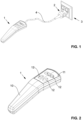
- the call button set according to the 1 shows the call button 1 designed as a pear button, which is connected to the plug 2 via the cable 4 .
- Plug 2 is connected to socket 3.
- the call button 1 designed as a pear button according to the 2 has a button housing 10 with recesses at the button positions 12.
- the area of the button positions 12 is covered by means of a transparent tactile membrane 11 shown.
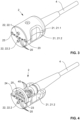
- the 3 shows the plug 2 with the plug housing 21, which can be divided into an upper half 21.1 and a lower half 21.2.
- the four plug contact pins 20 are arranged in a row in the parting plane between the two housing halves 21.1, 21.2.
- One of the bar magnet recesses 23 is located to the side of this row of plug contact pins 20.
- the two circular-cylindrical coding pins 22 are also located on the end face of the plug housing 21.
- the coding pin 22 of the first form 22.1 which is formed on the upper half 21.1 of the plug housing 21, has a larger diameter than the coding pin 22 of the second form 22.2 formed on the lower half 21.2 of the connector housing 21.
- the broken representation of the connector 2 according to the 4 shows the fastening of the four plug contact pins 20 in the plug connector strip 25 as well as the individual lines 40 running from the plug contact pins 20 into the cable 4.
- the plug ring magnet 24 is located directly behind the front wall of the plug housing 21.
- the socket 3 is according to figure 5 designed as a wall socket 3.1.
- the socket housing 31 has the four insertion openings 39 arranged in a row in which the socket contact pins 30 are located.
- the row of insertion openings 39 is bordered by the two bar magnets 33 protruding from the socket housing 31 .
- the two coding peg holes 32 are arranged centrally above and below the row of insertion openings 39, the coding peg hole 32 of the first form 32.1 in turn having a larger diameter than the coding peg hole 32 of the second form 32.2.
- the coupling socket 3.2 according to 6 largely corresponds to the wall socket 3.1 according to the figure 5 .
- the socket housing 31 is designed to be dismantled, it being divisible in the plane of the socket contact pins 30 into the upper half 31.1 of the socket housing 31 and the lower half 31.2 of the socket housing 31.
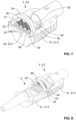
- socket 3 shows the broken representation of the clutch socket 3.2 according to 7 additionally the storage and attachment of the socket contact pins 30 within the socket ring magnet 34 surrounding the socket contact pins 30.
- Each of the socket contact pins 30 is mounted in the respective insertion opening 39 and in a sliding bearing 36 in an axially displaceable manner.
- the plain bearings 36 are fastened in the socket pin strip 35.
- the compression spring 37 designed as a spiral spring places the respective socket contact pin 30 under compression spring tension.
- the stop nut 38 prevents the socket contact pin 30 from slipping through the plain bearing 36.
- the 8 illustrates the formation of the plug connection from the plug 2 and the socket 3 designed as a coupling socket 3.2.
- the socket housing 31 has recesses in the form of so-called insert nests, into which the respective individual components can be inserted with a precise fit.
- one of the plug contact pins 20 touches one of the socket contact pins 30, which is under compression spring tension.
- the magnetic adhesion of plug 2 and socket 3 is brought about by the ring magnets 24 , 34 placed close to one another but not touching, and by the touching contact via the bar magnets 33 .
Landscapes
- Physics & Mathematics (AREA)
- Electromagnetism (AREA)
- General Physics & Mathematics (AREA)
- Details Of Connecting Devices For Male And Female Coupling (AREA)
Description
- Die Erfindung betrifft ein für den Einsatz in Licht- bzw. Patientenrufsystemen vorgesehenes kabelgebundenes Tasterset mit einem Ruftaster sowie einem Steckverbinder.
- Lichtrufsysteme sind elektro-optisches Meldesysteme, die in der Krankenpflege in Krankenhäusern, Hospitälern und anderen Pflegeeinrichtungen angewendet werden. Als Auslöseeinrichtung des Lichtrufs dient das sogenannte Ruf- oder Bettenmodul. Der Ruftaster dieses Rufmoduls ist gewöhnlich über ein Kabel und einen Steckverbinder an das Lichtrufsystem angeschlossen. Dieser Ruftaster, der zumeist als Birntaster ausgeführt ist, bildet zusammen mit dem Kabel und dem Steckverbinder das Tasterset.
- Der Steckverbinder muss, um die Erdrosslungsgefahr von Patienten durch das am Ruftaster befestigte Kabel zu minimieren, leicht lösbar sein. Dies kann zum Beispiel - wie in
DE 20 2014 004 494 U1 beschrieben - mittels eines magnetischen Verbindungssystems erfolgen. - Solche magnetischen Steckverbinder in verschiedenen Ausführungen sind unter anderem aus
DE 18 05 539 A ,DE 36 22 948 A1 oderDE 20 2018 101 382 U1 bekannt. - Ein Tasterset für Lichtrufsysteme gemäß dem Oberbegriff des Anspruchs 1 ist in
US 9 806 458 - Aufgabe der Erfindung ist es, ein kabelgebundenes Ruftasterset bereitzustellen, das einfach zu installieren ist, die erforderliche Signalübertragung sicherstellt und sich im Bedarfsfall leicht trennen lässt.
- Diese Aufgabe wird durch ein Ruftasterset für Lichtrufsysteme mit den kennzeichnenden Merkmalen nach dem Anspruch 1 gelöst; zweckmäßige Weiterbildungen der Erfindung sind in den Ansprüchen 2 bis 10 aufgeführt.
- Das Tasterset umfasst einen Ruftaster sowie einen Steckverbinder, der einen über ein Kabel mit dem Ruftaster verbundenen Stecker und eine zum Stecker passende Buchse aufweist.
- Der Stecker und die Buchse besitzen jeweils ein elektrisch isolierendes Steckergehäuse bzw. ein elektrisch isolierendes Buchsengehäuse. Im zusammengesteckten Zustand des Steckverbinders berührt der Stecker mit einer stirnseitig angeordneten, ebenen Kontaktfläche des Steckergehäuses die Buchse an einer ebenfalls stirnseitig angeordneten ebenen Kontaktfläche des Buchsengehäuses.
- Erfindungsgemäß sind an der zur Kontaktfläche abgewandten Seite des Steckergehäuses ein Stecker-Ringmagnet und an der zur Kontaktfläche abgewandten Seite des Buchsengehäuses ein Buchsen-Ringmagnet anbracht. Beide die gleiche Kreisringgeometrie aufweisende Ringmagnete besitzen im zusammengesteckten Zustand übereinstimmende Ringmagnetachsen, d. h., sie sind koaxial zueinander ausgerichtet. Die Ringmagnete sind zudem so ausgebildet und angeordnet, dass sie sich im zusammengesteckten Zustand magnetisch anziehen.
- Der Stecker besitzt ferner mehrere aus der Kontaktfläche des Steckergehäuses herausragende, vom Stecker-Ringmagnet umschlossene Steckerkontaktstifte. Diese sind parallel zu Ringmagnetachse des Stecker-Ringmagnets in einer Reihe und in einer radial zur Ringmagnetachse des Stecker-Ringmagnets verlaufenden Teilungsebene angeordnet. Im zusammengesteckten Zustand des Steckverbinders greifen die Steckerkontaktstifte passgenau in korrespondierende Einstecköffnungen im Buchsengehäuse ein.
- Die Buchse weist zudem mehrere, jeweils an der Position der Einstecköffnungen angeordnete Buchsenkontaktstifte auf, die im zusammengesteckten Zustand jeweils einen korrespondierenden koaxial ausgerichteten Steckerkontaktstift unter Ausbildung einer elektrischen Verbindung stirnseitig kontaktieren.
- Zudem weist die Buchse zwei beidseitig der Reihe der Einstecköffnungen angeordnete, aus der Kontaktfläche des Buchsengehäuses herausragende Stabmagnete auf. D. h., einer der Stabmagnete ist vor der ersten der in Reihe liegenden Einstecköffnungen und der andere Stabmagnet hinter der letzten der in Reihe liegenden Einstecköffnungen angeordnet. Die beiden Stabmagnete sind magnetisch anziehend stirnseitig am Buchsen-Ringmagnet befestigt. Im zusammengesteckten Zustand des Steckverbinders greifen die Stabmagnete passgenau in korrespondierende Stabmagnetaussparungen im Steckergehäuse ein, wobei sie den Stecker-Ringmagnet stirnseitig berühren.
- Bei Installation des Ruftastersets wird der vorzugsweise als Birntaster ausgeführte Ruftaster so am Bett eines Patienten bzw. einer Patientin angebracht, dass dieser bzw. diese ihn leicht erreichen kann. Der Stecker wird an die entsprechende Buchse angesteckt, die sowohl als Wandbuchse oder als auch als Kupplungsbuchse ausgebildet sein kann. Der Stecker haftet durch die magnetische Anziehung der Ringmagnete und der Stabmagnete an der Buchse mit einer definierten magnetischen Haftkraft. Wird dieses Haftkraft überschritten, zum Beispiel durch versehentlichen Zug am Kabel beim Umsetzen des Bettes, löst sich der Stecker ohne Verklemmen von der Buchse.
- Die latente Erdrosselungsgefahr, die von dem am Ruftaster befestigten Kabel ausgeht, wird hierdurch auf ein Minimum reduziert. Zudem verhindert die leichte Lösbarkeit des Steckverbinders die Beschädigung der Baugruppen beim ungewollten Trennen.
- Gemäß einer Ausführung des Ruftastersets weist der Stecker vier Steckerkontaktstifte auf, die in Reihe mit gleichem Abstand zueinander und symmetrisch zur Ringmagnetachse des Stecker-Ringmagnets angeordnet sind.
- Der Stecker-Ringmagnet, der Buchsen-Ringmagnet und die Stabmagnete sind vorzugweise axial magnetisierte Permanentmagnete. Als geeignet haben sich u. a. Neodym-Eisen-Bor-Magnete erwiesen.
- Die magnetische Haltekraft des Steckverbinders liegt vorzugsweise bei maximal 4 N; dies gewährleistet ein gefahrloses Trennen bei unsachgemäßer Bettbewegung. Die magnetische Haltekraft des Steckverbinders sollte bei mindestens 1 N liegen, um die ausreichende Haftung des Steckers sicherzustellen.
- Um ein korrektes Einstecken des Steckers in die Buchse zu gewährleisten, kann der Stecker mit einer Kodierung ausgeführt sein. Hierzu weist der Steckverbinder beispielsweise zwei am Stecker aus der Kontaktfläche des Steckergehäuses auskragende, sich geometrisch voneinander unterscheidende Kodierzapfen auf, die beidseitig der Teilungsebene in einer radial zur Ringmagnetachse des Stecker-Ringmagnets und senkrecht zur Teilungsebene verlaufenden Kodierzapfenebene angeordnet sind. Im zusammengesteckten Zustand des Steckverbinders greifen die Kodierzapfen passgenau in korrespondierende, im Buchsengehäuse eingebrachte Kodierzapfenlöcher ein. Die Kodierzapfen (bzw. die entsprechenden Kodierzapfenlöcher) sind vorzugsweise symmetrisch zur Ringmagnetachse des Stecker-Ringmagnets (bzw. zur Ringmagnetachse des Buchsen-Ringmagnets) angeordnet. Die kreuzweise Anordnung der Steckerkontaktstifte und der Kodierzapfen verbessert die Stabilität der Steckverbindung bei ungewollter Berührung.
- Gemäß einer weiteren Ausgestaltung des Ruftastersets ist jeder der Buchsenkontaktstifte in jeweils einem Gleitlager axial beweglich unter Federdruckspannung gelagert. Hierdurch werden die Buchsenkontaktstifte mit ihrer Stirnseite stetig gegen die korrespondierende Stirnseite der Steckerkontaktstifte gepresst. Dies wiederum stellt sicher, dass der elektrische Kontakt auch bei geringfügiger Schiefstellungen des Steckers aufrecht erhalten bleibt. Die Federdruckspannung wird beispielsweise mittels einer Druckfeder erzeugt, die den im Gleitlager axial geführten Buchsenkontaktstift im zusammengesteckten Zustand gegen den Steckerkontaktstift drückt. Vorzugswiese liegt der Federweg der Buchsenkontaktstifte im Bereich von ca. 1,5 mm.
- Ferner können sowohl der Stecker als auch die Buchse in der Ausführung als Kupplungsbuchse teilbar ausbildet sein. Hierzu weisen der Stecker ein in der Teilungsebene teilbares Steckergehäuse und/oder die Kupplungsbuchse ein entsprechend teilbares Buchsengehäuse auf.
- Die Erfindung ist nachfolgend anhand von Ausführungsbeispielen und mit Bezug auf die schematischen Zeichnungen näher erläutert, wobei gleiche oder ähnliche Merkmale mit gleichen Bezugszeichen versehen sind. Dazu veranschaulichen:
- Fig. 1:
- das Ruftasterset in perspektivischer Ansicht,
- Fig. 2:
- den Ruftaster in perspektivischer Ansicht,
- Fig. 3:
- den Stecker in perspektivischer Ansicht,
- Fig. 4:
- den Stecker in aufgebrochener, perspektivischer Ansicht,
- Fig. 5:
- die Wandbuchse in perspektivischer Ansicht,
- Fig. 6:
- die Kupplungsbuchse in perspektivischer Ansicht,
- Fig. 7:
- die Kupplungsbuchse in aufgebrochener, perspektivischer Ansicht und
- Fig. 8:
- den Steckverbinder in aufgebrochener, perspektivischer Ansicht.
- Das Ruftasterset gemäß der
Fig. 1 zeigt den als Birntaster ausgeführten Ruftaster 1, der über das Kabel 4 mit dem Stecker 2 verbunden ist. Der Stecker 2 ist an die Buchse 3 angeschlossen. - Der als Birntaster ausgeführte Ruftaster 1 gemäß der
Fig. 2 besitzt ein Tastergehäuse 10 mit Aussparungen an den Tasterpositionen 12. Der Bereich der Tasterpositionen 12 ist mittels einer transparent dargestellten Tastfolie 11 abgedeckt. - Die
Fig. 3 zeigt den Stecker 2 mit dem in eine obere Hälfte 21.1 und eine untere Hälfte 21.2 teilbaren Steckergehäuse 21. In der Teilungsebene zwischen den beiden Gehäusehälften 21.1, 21.2 sind die vier Steckerkontaktstifte 20 in Reihe angeordnet. Seitlich dieser Reihe der Steckerkontaktstifte 20 befindet sich jeweils eine der Stabmagnetaussparungen 23. An der Stirnseite des Steckergehäuses 21 befinden sich zudem die beiden, kreiszylinderförmigen Kodierzapfen 22. Der an der oberen Hälfte 21.1 des Steckergehäuses 21 ausgebildete Kodierzapfen 22 der ersten Form 22.1 besitzt einen größeren Durchmesser als der an der unteren Hälfte 21.2 des Steckergehäuses 21 ausgebildete Kodierzapfen 22 der zweiten Form 22.2. - Die aufgebrochene Darstellung des Steckers 2 gemäß der
Fig. 4 zeigt die Befestigung der vier Steckerkontaktstifte 20 in der Steckerstiftleiste 25 sowie die von den Steckerkontaktstiften 20 in das Kabel 4 laufenden Einzelleitungen 40. Der Stecker-Ringmagnet 24 befindet sich direkt hinter der stirnseitigen Wandung des Steckergehäuses 21. - Die Buchse 3 ist gemäß
Fig. 5 als Wandbuchse 3.1 ausgeführt. Das Buchsengehäuse 31 besitzt die vier in einer Reihe angeordneten Einstecköffnungen 39 in denen sich die Buchsenkontaktstifte 30 befinden. Die Reihe der Einstecköffnungen 39 ist von den beiden aus dem Buchsengehäuse 31 herausragenden Stabmagneten 33 eingefasst. - Die beiden Kodierzapfenlöcher 32 sind mittig ober- und unterhalb der Reihe der Einstecköffnungen 39 angeordnet, wobei das Kodierzapfenloch 32 der ersten Form 32.1 wiederum einen größeren Durchmesser aufweist als das Kodierzapfenloch 32 der zweiten Form 32.2.
- Die Kupplungsbuchse 3.2 gemäß der
Fig. 6 entspricht weitestgehend der Wandbuchse 3.1 nach derFig. 5 . Das Buchsengehäuse 31 ist zerlegbar ausgeführt, wobei es in der Ebene der Buchsenkontaktstifte 30 in die obere Hälfte 31.1 des Buchsengehäuses 31 und in die untere Hälfte 31.2 des Buchsengehäuses 31 teilbar ist. - Neben den bereits in der
Fig. 5 und derFig. 6 beschriebenen Komponenten der Buchse 3 zeigt die aufgebrochene Darstellung der Kupplungsbuchse 3.2 gemäß derFig. 7 zusätzlich die Lagerung und Befestigung der Buchsenkontaktstifte 30 innerhalb des die Buchsenkontaktstifte 30 umschließenden Buchsen-Ringmagnets 34. - Jeder der Buchsenkontaktstifte 30 ist in der jeweiligen Einstecköffnung 39 und in einem Gleitlager 36 axial verschiebbar gelagert. Die Gleitlager 36 sind in der Buchsenstiftleiste 35 befestigt. Die als Spiralfeder ausgebildete Druckfeder 37 setzt den jeweiligen Buchsenkontaktstift 30 unter Druckfederspannung. Das Durchrutschen des Buchsenkontaktstifts 30 durch das Gleitlager 36 verhindert die Anschlagmutter 38.
- Die
Fig. 8 veranschaulicht die Ausbildung der Steckverbindung aus dem Stecker 2 und der als Kupplungsbuchse 3.2 ausgeführten Buchse 3. In der dargestellten unteren Hälfte 21.2 des Steckergehäuses 21 und der unteren Hälfte 31.2. des Buchsengehäuses 31 sind Aussparungen in Form sogenannter Einlegenester eingebracht, in die die jeweiligen Einzelkomponenten passgenau einsetzbar sind. - Im zusammengesteckten Zustand berührt jeweils einer der Steckerkontaktstifte 20 einen der unter Druckfederspannung stehenden Buchsenkontaktstifte 30.
- Die magnetische Haftung von Stecker 2 und Buchse 3 wird durch die nahe zueinander platzierten, sich jedoch nicht berührenden Ringmagnete 24, 34 sowie den berührenden Kontakt über die Stabmagnete 33 bewirkt.
-
- 1
- Ruftaster
- 2
- Stecker
- 3
- Buchse
- 3.1
- Wandbuchse
- 3.2
- Kupplungsbuchse
- 4
- Kabel
- 10
- Tastergehäuse
- 11
- Tastfolie
- 12
- Tasterpositionen
- 20
- Steckerkontaktstift
- 21
- Steckergehäuse
- 21.1
- Steckergehäuse, obere Hälfte
- 21.2
- Steckergehäuse, untere Hälfte
- 22
- Kodierzapfen
- 22.1
- Kodierzapfen, erste Form
- 22.2
- Kodierzapfen, zweite Form
- 23
- Stabmagnetaussparung
- 24
- Stecker-Ringmagnet
- 25
- Steckerstiftleiste
- 30
- Buchsenkontaktstift
- 31
- Buchsengehäuse
- 31.1
- Buchsengehäuse, obere Hälfte
- 31.2
- Buchsengehäuse, untere Hälfte
- 32
- Kodierzapfenloch
- 32.1
- Kodierzapfenloch, erste Form
- 32.2
- Kodierzapfenloch, zweite Form
- 33
- Stabmagnet
- 34
- Buchsen-Ringmagnet
- 35
- Buchsenstiftleiste
- 36
- Gleitlager
- 37
- Druckfeder
- 38
- Anschlagmutter
- 39
- Einstecköffnung
- 40
- Einzelleitungen
Claims (10)
- Tasterset für Lichtrufsysteme, umfassend einen Ruftaster (1) und einen Steckverbinder, wobei- der Steckverbinder einen über ein Kabel (4) mit dem Ruftaster (1) verbundenen Stecker (2) und eine zum Stecker (2) passende Buchse (3) aufweist,- der Stecker (2) ein elektrisch isolierendes Steckergehäuse (21) und die Buchse (3) ein elektrisch isolierendes Buchsengehäuse (31) besitzt, und- der Stecker (2) mit einer stirnseitig angeordneten, ebenen Kontaktfläche des Steckergehäuses (21) die Buchse (3) an einer ebenfalls stirnseitig angeordneten, ebenen Kontaktfläche des Buchsengehäuses (31) im zusammengesteckten Zustand berührt,- die Buchse (3) mehrere jeweils an der Position der Einstecköffnungen (39) angeordnete Buchsenkontaktstifte (30) aufweist, die im zusammengesteckten Zustand jeweils einen korrespondierenden, koaxial ausgerichteten Steckerkontaktstift (20) unter Ausbildung einer elektrischen Verbindung stirnseitig kontaktieren,dadurch gekennzeichnet, dass- an der zur Kontaktfläche abgewandten Seite des Steckergehäuses (21) ein Stecker-Ringmagnet (24) und an der zur Kontaktfläche abgewandten Seite des Buchsengehäuses (31) ein Buchsen-Ringmagnet (34) anbracht sind, wobei die beiden die gleiche Kreisringgeometrie aufweisenden Ringmagnete (24, 34) im zusammengesteckten Zustand übereinstimmende Ringmagnetachsen besitzen und sich gegenseitig magnetisch anziehen,- der Stecker (2) mehrere aus der Kontaktfläche des Steckergehäuses (21) herausragende, vom Stecker-Ringmagnet (24) umschlossene Steckerkontaktstifte (20) aufweist, die parallel zu Ringmagnetachse des Stecker-Ringmagnets (24) in einer Reihe und in einer radial zur Ringmagnetachse des Stecker-Ringmagnets (24) verlaufenden Teilungsebene angeordnet sind, wobei die Steckerkontaktstifte (20) im zusammengesteckten Zustand in korrespondierende Einstecköffnungen (39) im Buchsengehäuse (31) passgenau eingreifen,- die Buchse (3) zwei beidseitig der Reihe der Einstecköffnungen (39) angeordnete, aus der Kontaktfläche des Buchsengehäuses (31) herausragende Stabmagnete (33) aufweist, die magnetisch anziehend, stirnseitig am Buchsen-Ringmagnet (34) befestigt sind, und die im zusammengesteckten Zustand in korrespondierende Stabmagnetaussparungen (23) im Steckergehäuse (21) passgenau eingreifen, wobei die Stabmagnete (33) den Stecker-Ringmagnet (24), magnetisch haftend, stirnseitig berühren.
- Tasterset nach Anspruch 1, dadurch gekennzeichnet, dass der Stecker (2) vier Steckerkontaktstifte (20) aufweist, die in Reihe mit gleichem Abstand zueinander und symmetrisch zur Ringmagnetachse des Stecker-Ringmagnets (24) angeordnet sind.
- Tasterset nach Anspruch 1 oder 2, dadurch gekennzeichnet, dass der Stecker-Ringmagnet (24), der Buchsen-Ringmagnet (34) und die Stabmagnete (33) axial magnetisierte Permanentmagnete sind.
- Tasterset nach einem der Ansprüche 1 bis 3, dadurch gekennzeichnet, dass der die magnetische Haltekraft des Steckverbinders im Bereich von 1 N bis 4 N liegt.
- Tasterset nach einem der Ansprüche 1 bis 4, dadurch gekennzeichnet, dass der Steckverbinder zwei am Stecker (2) aus der Kontaktfläche des Steckergehäuses (21) auskragende, sich geometrisch voneinander unterscheidende Kodierzapfen (22) aufweist, die beidseitig der Teilungsebene in einer radial zur Ringmagnetachse des Stecker-Ringmagnets (24) und senkrecht zur Teilungsebene verlaufenden Kodierzapfenebene angeordnet sind, wobei im Buchsengehäuse (31) korrespondierende Kodierzapfenlöcher (32) eingebracht sind, in die die Kodierzapfen (22) im zusammengesteckten Zustand passgenau eingreifen.
- Tasterset nach Anspruch 5, dadurch gekennzeichnet, dass die Kodierzapfen (22) symmetrisch zur Ringmagnetachse des Stecker-Ringmagnets (24) angeordnet sind
- Tasterset nach einem der Ansprüche 1 bis 6, dadurch gekennzeichnet, dass jeder der Buchsenkontaktstifte (30) in jeweils einem Gleitlager (36) axial beweglich unter Federdruckspannung gelagert ist.
- Tasterset nach einem der Ansprüche 1 bis 7, dadurch gekennzeichnet, dass der Stecker (2) ein in der Teilungsebene teilbares Steckergehäuse (21) aufweist.
- Tasterset nach einem der Ansprüche 1 bis 8, dadurch gekennzeichnet, dass die Buchse (3) eine Wandbuchse (3.1) oder einer Kupplungsbuchse (3.2) ist.
- Tasterset nach Anspruch 9, wobei die Buchse (3) eine Kupplungsbuchse (3.2) ist, dadurch gekennzeichnet, dass die Kupplungsbuchse (3.2) ein teilbares Buchsengehäuse (31) aufweist.
Applications Claiming Priority (1)
| Application Number | Priority Date | Filing Date | Title |
|---|---|---|---|
| DE202020107107.6U DE202020107107U1 (de) | 2020-12-09 | 2020-12-09 | Tasterset für Lichtrufsysteme |
Publications (3)
| Publication Number | Publication Date |
|---|---|
| EP4012849A1 EP4012849A1 (de) | 2022-06-15 |
| EP4012849B1 true EP4012849B1 (de) | 2023-06-07 |
| EP4012849C0 EP4012849C0 (de) | 2023-06-07 |
Family
ID=75155973
Family Applications (1)
| Application Number | Title | Priority Date | Filing Date |
|---|---|---|---|
| EP21211876.4A Active EP4012849B1 (de) | 2020-12-09 | 2021-12-02 | Tasterset für lichtrufsysteme |
Country Status (2)
| Country | Link |
|---|---|
| EP (1) | EP4012849B1 (de) |
| DE (1) | DE202020107107U1 (de) |
Family Cites Families (7)
| Publication number | Priority date | Publication date | Assignee | Title |
|---|---|---|---|---|
| CH489121A (fr) | 1967-11-01 | 1970-04-15 | Cuttat Francois | Dispositif de couplage électrique à prise et à fiche pour courant faible et pour tension réduite |
| DE3622948A1 (de) | 1986-07-08 | 1988-01-21 | Heinz Eichholz | Kontaktanordnung zur herstellung einer leitenden elektrischen verbindung |
| US7264479B1 (en) * | 2006-06-02 | 2007-09-04 | Lee Vincent J | Coaxial cable magnetic connector |
| DE202014004494U1 (de) | 2014-05-27 | 2014-08-18 | Winkel Gmbh | Magnetisches Verbindugssystem zur Aufnahme von Auslöseeinheiten für Rufanlagen |
| US9806458B1 (en) * | 2016-10-21 | 2017-10-31 | Gt Contact Co., Ltd. | Electrically connecting device, electrical connector, and mating connector |
| DE202018101382U1 (de) | 2018-03-12 | 2018-03-28 | Sun Shen Enterprise Co., Ltd. | Magnetischer elektrischer Steckverbinder |
| US11070004B2 (en) * | 2019-02-06 | 2021-07-20 | Vincent Lee | Magnetic connector assembly |
-
2020
- 2020-12-09 DE DE202020107107.6U patent/DE202020107107U1/de not_active Expired - Lifetime
-
2021
- 2021-12-02 EP EP21211876.4A patent/EP4012849B1/de active Active
Also Published As
| Publication number | Publication date |
|---|---|
| EP4012849A1 (de) | 2022-06-15 |
| EP4012849C0 (de) | 2023-06-07 |
| DE202020107107U1 (de) | 2021-03-08 |
Similar Documents
| Publication | Publication Date | Title |
|---|---|---|
| EP2553771B1 (de) | Elektrisches verbindungssystem | |
| EP2510590B1 (de) | Systemsteckverbinder mit adaptermodul | |
| DE69724011T2 (de) | Optischer steckverbinder | |
| DE69508502T2 (de) | Elektrischer Verbinder mit zweifachverriegelter Kontakthaltevorrichtung | |
| DE102015015202B4 (de) | Steckverbinder und Stecksystem | |
| DE2316582A1 (de) | Elektrisches verbindungsstueck | |
| EP0852829B1 (de) | Anordnung zum verbinden von einem elektrischen stecker mit einem komplementären stecker | |
| DE3883053T2 (de) | Elektrisches Kontakthalterungssystem, Methode und Werkzeug für sein Entfernen. | |
| DE102007063207A1 (de) | Steckverbinder | |
| DE2045474C3 (de) | Kabelanschlußvorrichtung mit Steckkontakten | |
| EP3588684A1 (de) | Direktstecker und direktsteckverbindung | |
| DE102020111610A1 (de) | Verriegelungsmechanismus für einen Hochstromsteckverbinder | |
| DE69420385T2 (de) | Elektrische Steckeranordnung | |
| WO2008052845A2 (de) | Steckverbindung, insbesondere für sensor-/aktorleitungen | |
| EP1523690A1 (de) | Zweipoliger optischer steckverbinder | |
| EP4012849B1 (de) | Tasterset für lichtrufsysteme | |
| DE2128954B2 (de) | Elektrische Steckverbindung | |
| DE102015207411A1 (de) | Vorrichtung zur elektrischen Kontaktierung | |
| EP1152496B1 (de) | Steckvorrichtung | |
| EP1154521A1 (de) | Steckverbinder und Verfahren zur Montage eines Steckverbinders | |
| DE102022107678A1 (de) | Verbinder und Verbinderanordnung | |
| DE102016001575B4 (de) | Steckverbinder, Sockel und Stecksystem | |
| EP2192658B1 (de) | Verbindungseinrichtung | |
| DE10020191C2 (de) | Elektrische Steckverbindung zur Kontaktierung von elektrisch leitfähigen Kabeln mit einer Mehrzahl von Einzelleitern | |
| EP0127849A2 (de) | Relais |
Legal Events
| Date | Code | Title | Description |
|---|---|---|---|
| PUAI | Public reference made under article 153(3) epc to a published international application that has entered the european phase |
Free format text: ORIGINAL CODE: 0009012 |
|
| STAA | Information on the status of an ep patent application or granted ep patent |
Free format text: STATUS: THE APPLICATION HAS BEEN PUBLISHED |
|
| AK | Designated contracting states |
Kind code of ref document: A1 Designated state(s): AL AT BE BG CH CY CZ DE DK EE ES FI FR GB GR HR HU IE IS IT LI LT LU LV MC MK MT NL NO PL PT RO RS SE SI SK SM TR |
|
| STAA | Information on the status of an ep patent application or granted ep patent |
Free format text: STATUS: REQUEST FOR EXAMINATION WAS MADE |
|
| 17P | Request for examination filed |
Effective date: 20220711 |
|
| RBV | Designated contracting states (corrected) |
Designated state(s): AL AT BE BG CH CY CZ DE DK EE ES FI FR GB GR HR HU IE IS IT LI LT LU LV MC MK MT NL NO PL PT RO RS SE SI SK SM TR |
|
| GRAP | Despatch of communication of intention to grant a patent |
Free format text: ORIGINAL CODE: EPIDOSNIGR1 |
|
| STAA | Information on the status of an ep patent application or granted ep patent |
Free format text: STATUS: GRANT OF PATENT IS INTENDED |
|
| RIC1 | Information provided on ipc code assigned before grant |
Ipc: H01R 13/62 20060101ALI20220826BHEP Ipc: H01R 13/24 20060101ALI20220826BHEP Ipc: G08B 5/22 20060101ALI20220826BHEP Ipc: H01R 13/645 20060101AFI20220826BHEP |
|
| INTG | Intention to grant announced |
Effective date: 20220928 |
|
| GRAS | Grant fee paid |
Free format text: ORIGINAL CODE: EPIDOSNIGR3 |
|
| GRAA | (expected) grant |
Free format text: ORIGINAL CODE: 0009210 |
|
| STAA | Information on the status of an ep patent application or granted ep patent |
Free format text: STATUS: THE PATENT HAS BEEN GRANTED |
|
| AK | Designated contracting states |
Kind code of ref document: B1 Designated state(s): AL AT BE BG CH CY CZ DE DK EE ES FI FR GB GR HR HU IE IS IT LI LT LU LV MC MK MT NL NO PL PT RO RS SE SI SK SM TR |
|
| REG | Reference to a national code |
Ref country code: GB Ref legal event code: FG4D Free format text: NOT ENGLISH |
|
| REG | Reference to a national code |
Ref country code: CH Ref legal event code: EP Ref country code: AT Ref legal event code: REF Ref document number: 1577728 Country of ref document: AT Kind code of ref document: T Effective date: 20230615 |
|
| REG | Reference to a national code |
Ref country code: DE Ref legal event code: R096 Ref document number: 502021000831 Country of ref document: DE |
|
| U01 | Request for unitary effect filed |
Effective date: 20230607 |
|
| U07 | Unitary effect registered |
Designated state(s): AT BE BG DE DK EE FI FR IT LT LU LV MT NL PT SE SI Effective date: 20230612 |
|
| REG | Reference to a national code |
Ref country code: LT Ref legal event code: MG9D |
|
| PG25 | Lapsed in a contracting state [announced via postgrant information from national office to epo] |
Ref country code: NO Free format text: LAPSE BECAUSE OF FAILURE TO SUBMIT A TRANSLATION OF THE DESCRIPTION OR TO PAY THE FEE WITHIN THE PRESCRIBED TIME-LIMIT Effective date: 20230907 Ref country code: ES Free format text: LAPSE BECAUSE OF FAILURE TO SUBMIT A TRANSLATION OF THE DESCRIPTION OR TO PAY THE FEE WITHIN THE PRESCRIBED TIME-LIMIT Effective date: 20230607 |
|
| PG25 | Lapsed in a contracting state [announced via postgrant information from national office to epo] |
Ref country code: RS Free format text: LAPSE BECAUSE OF FAILURE TO SUBMIT A TRANSLATION OF THE DESCRIPTION OR TO PAY THE FEE WITHIN THE PRESCRIBED TIME-LIMIT Effective date: 20230607 Ref country code: HR Free format text: LAPSE BECAUSE OF FAILURE TO SUBMIT A TRANSLATION OF THE DESCRIPTION OR TO PAY THE FEE WITHIN THE PRESCRIBED TIME-LIMIT Effective date: 20230607 Ref country code: GR Free format text: LAPSE BECAUSE OF FAILURE TO SUBMIT A TRANSLATION OF THE DESCRIPTION OR TO PAY THE FEE WITHIN THE PRESCRIBED TIME-LIMIT Effective date: 20230908 |
|
| U20 | Renewal fee for the european patent with unitary effect paid |
Year of fee payment: 3 Effective date: 20231116 |
|
| PG25 | Lapsed in a contracting state [announced via postgrant information from national office to epo] |
Ref country code: SK Free format text: LAPSE BECAUSE OF FAILURE TO SUBMIT A TRANSLATION OF THE DESCRIPTION OR TO PAY THE FEE WITHIN THE PRESCRIBED TIME-LIMIT Effective date: 20230607 |
|
| PG25 | Lapsed in a contracting state [announced via postgrant information from national office to epo] |
Ref country code: IS Free format text: LAPSE BECAUSE OF FAILURE TO SUBMIT A TRANSLATION OF THE DESCRIPTION OR TO PAY THE FEE WITHIN THE PRESCRIBED TIME-LIMIT Effective date: 20231007 |
|
| PG25 | Lapsed in a contracting state [announced via postgrant information from national office to epo] |
Ref country code: SM Free format text: LAPSE BECAUSE OF FAILURE TO SUBMIT A TRANSLATION OF THE DESCRIPTION OR TO PAY THE FEE WITHIN THE PRESCRIBED TIME-LIMIT Effective date: 20230607 Ref country code: SK Free format text: LAPSE BECAUSE OF FAILURE TO SUBMIT A TRANSLATION OF THE DESCRIPTION OR TO PAY THE FEE WITHIN THE PRESCRIBED TIME-LIMIT Effective date: 20230607 Ref country code: RO Free format text: LAPSE BECAUSE OF FAILURE TO SUBMIT A TRANSLATION OF THE DESCRIPTION OR TO PAY THE FEE WITHIN THE PRESCRIBED TIME-LIMIT Effective date: 20230607 Ref country code: IS Free format text: LAPSE BECAUSE OF FAILURE TO SUBMIT A TRANSLATION OF THE DESCRIPTION OR TO PAY THE FEE WITHIN THE PRESCRIBED TIME-LIMIT Effective date: 20231007 Ref country code: CZ Free format text: LAPSE BECAUSE OF FAILURE TO SUBMIT A TRANSLATION OF THE DESCRIPTION OR TO PAY THE FEE WITHIN THE PRESCRIBED TIME-LIMIT Effective date: 20230607 |
|
| PG25 | Lapsed in a contracting state [announced via postgrant information from national office to epo] |
Ref country code: PL Free format text: LAPSE BECAUSE OF FAILURE TO SUBMIT A TRANSLATION OF THE DESCRIPTION OR TO PAY THE FEE WITHIN THE PRESCRIBED TIME-LIMIT Effective date: 20230607 |
|
| REG | Reference to a national code |
Ref country code: DE Ref legal event code: R097 Ref document number: 502021000831 Country of ref document: DE |
|
| PLBE | No opposition filed within time limit |
Free format text: ORIGINAL CODE: 0009261 |
|
| STAA | Information on the status of an ep patent application or granted ep patent |
Free format text: STATUS: NO OPPOSITION FILED WITHIN TIME LIMIT |
|
| 26N | No opposition filed |
Effective date: 20240308 |
|
| PG25 | Lapsed in a contracting state [announced via postgrant information from national office to epo] |
Ref country code: MC Free format text: LAPSE BECAUSE OF FAILURE TO SUBMIT A TRANSLATION OF THE DESCRIPTION OR TO PAY THE FEE WITHIN THE PRESCRIBED TIME-LIMIT Effective date: 20230607 |
|
| PG25 | Lapsed in a contracting state [announced via postgrant information from national office to epo] |
Ref country code: MC Free format text: LAPSE BECAUSE OF FAILURE TO SUBMIT A TRANSLATION OF THE DESCRIPTION OR TO PAY THE FEE WITHIN THE PRESCRIBED TIME-LIMIT Effective date: 20230607 |
|
| REG | Reference to a national code |
Ref country code: IE Ref legal event code: MM4A |
|
| PG25 | Lapsed in a contracting state [announced via postgrant information from national office to epo] |
Ref country code: IE Free format text: LAPSE BECAUSE OF NON-PAYMENT OF DUE FEES Effective date: 20231202 |
|
| PG25 | Lapsed in a contracting state [announced via postgrant information from national office to epo] |
Ref country code: IE Free format text: LAPSE BECAUSE OF NON-PAYMENT OF DUE FEES Effective date: 20231202 |
|
| U20 | Renewal fee for the european patent with unitary effect paid |
Year of fee payment: 4 Effective date: 20241029 |
|
| PG25 | Lapsed in a contracting state [announced via postgrant information from national office to epo] |
Ref country code: CY Free format text: LAPSE BECAUSE OF FAILURE TO SUBMIT A TRANSLATION OF THE DESCRIPTION OR TO PAY THE FEE WITHIN THE PRESCRIBED TIME-LIMIT; INVALID AB INITIO Effective date: 20211202 |
|
| PG25 | Lapsed in a contracting state [announced via postgrant information from national office to epo] |
Ref country code: TR Free format text: LAPSE BECAUSE OF FAILURE TO SUBMIT A TRANSLATION OF THE DESCRIPTION OR TO PAY THE FEE WITHIN THE PRESCRIBED TIME-LIMIT Effective date: 20230607 |
|
| REG | Reference to a national code |
Ref country code: CH Ref legal event code: U11 Free format text: ST27 STATUS EVENT CODE: U-0-0-U10-U11 (AS PROVIDED BY THE NATIONAL OFFICE) Effective date: 20260101 |
|
| U20 | Renewal fee for the european patent with unitary effect paid |
Year of fee payment: 5 Effective date: 20251128 |
|
| PGFP | Annual fee paid to national office [announced via postgrant information from national office to epo] |
Ref country code: CH Payment date: 20260101 Year of fee payment: 5 |