EP4012315A1 - Heat exchanger and refrigeration cycle apparatus - Google Patents
Heat exchanger and refrigeration cycle apparatus Download PDFInfo
- Publication number
- EP4012315A1 EP4012315A1 EP19940370.0A EP19940370A EP4012315A1 EP 4012315 A1 EP4012315 A1 EP 4012315A1 EP 19940370 A EP19940370 A EP 19940370A EP 4012315 A1 EP4012315 A1 EP 4012315A1
- Authority
- EP
- European Patent Office
- Prior art keywords
- heat transfer
- heat exchanger
- transfer pipes
- heat
- pipe
- Prior art date
- Legal status (The legal status is an assumption and is not a legal conclusion. Google has not performed a legal analysis and makes no representation as to the accuracy of the status listed.)
- Granted
Links
Images






Classifications
-
- F—MECHANICAL ENGINEERING; LIGHTING; HEATING; WEAPONS; BLASTING
- F28—HEAT EXCHANGE IN GENERAL
- F28F—DETAILS OF HEAT-EXCHANGE AND HEAT-TRANSFER APPARATUS, OF GENERAL APPLICATION
- F28F1/00—Tubular elements; Assemblies of tubular elements
- F28F1/10—Tubular elements and assemblies thereof with means for increasing heat-transfer area, e.g. with fins, with projections, with recesses
- F28F1/12—Tubular elements and assemblies thereof with means for increasing heat-transfer area, e.g. with fins, with projections, with recesses the means being only outside the tubular element
- F28F1/24—Tubular elements and assemblies thereof with means for increasing heat-transfer area, e.g. with fins, with projections, with recesses the means being only outside the tubular element and extending transversely
- F28F1/32—Tubular elements and assemblies thereof with means for increasing heat-transfer area, e.g. with fins, with projections, with recesses the means being only outside the tubular element and extending transversely the means having portions engaging further tubular elements
-
- F—MECHANICAL ENGINEERING; LIGHTING; HEATING; WEAPONS; BLASTING
- F28—HEAT EXCHANGE IN GENERAL
- F28D—HEAT-EXCHANGE APPARATUS, NOT PROVIDED FOR IN ANOTHER SUBCLASS, IN WHICH THE HEAT-EXCHANGE MEDIA DO NOT COME INTO DIRECT CONTACT
- F28D1/00—Heat-exchange apparatus having stationary conduit assemblies for one heat-exchange medium only, the media being in contact with different sides of the conduit wall, in which the other heat-exchange medium is a large body of fluid, e.g. domestic or motor car radiators
- F28D1/02—Heat-exchange apparatus having stationary conduit assemblies for one heat-exchange medium only, the media being in contact with different sides of the conduit wall, in which the other heat-exchange medium is a large body of fluid, e.g. domestic or motor car radiators with heat-exchange conduits immersed in the body of fluid
- F28D1/04—Heat-exchange apparatus having stationary conduit assemblies for one heat-exchange medium only, the media being in contact with different sides of the conduit wall, in which the other heat-exchange medium is a large body of fluid, e.g. domestic or motor car radiators with heat-exchange conduits immersed in the body of fluid with tubular conduits
-
- F—MECHANICAL ENGINEERING; LIGHTING; HEATING; WEAPONS; BLASTING
- F28—HEAT EXCHANGE IN GENERAL
- F28D—HEAT-EXCHANGE APPARATUS, NOT PROVIDED FOR IN ANOTHER SUBCLASS, IN WHICH THE HEAT-EXCHANGE MEDIA DO NOT COME INTO DIRECT CONTACT
- F28D1/00—Heat-exchange apparatus having stationary conduit assemblies for one heat-exchange medium only, the media being in contact with different sides of the conduit wall, in which the other heat-exchange medium is a large body of fluid, e.g. domestic or motor car radiators
- F28D1/02—Heat-exchange apparatus having stationary conduit assemblies for one heat-exchange medium only, the media being in contact with different sides of the conduit wall, in which the other heat-exchange medium is a large body of fluid, e.g. domestic or motor car radiators with heat-exchange conduits immersed in the body of fluid
- F28D1/04—Heat-exchange apparatus having stationary conduit assemblies for one heat-exchange medium only, the media being in contact with different sides of the conduit wall, in which the other heat-exchange medium is a large body of fluid, e.g. domestic or motor car radiators with heat-exchange conduits immersed in the body of fluid with tubular conduits
- F28D1/047—Heat-exchange apparatus having stationary conduit assemblies for one heat-exchange medium only, the media being in contact with different sides of the conduit wall, in which the other heat-exchange medium is a large body of fluid, e.g. domestic or motor car radiators with heat-exchange conduits immersed in the body of fluid with tubular conduits the conduits being bent, e.g. in a serpentine or zig-zag
-
- F—MECHANICAL ENGINEERING; LIGHTING; HEATING; WEAPONS; BLASTING
- F28—HEAT EXCHANGE IN GENERAL
- F28D—HEAT-EXCHANGE APPARATUS, NOT PROVIDED FOR IN ANOTHER SUBCLASS, IN WHICH THE HEAT-EXCHANGE MEDIA DO NOT COME INTO DIRECT CONTACT
- F28D1/00—Heat-exchange apparatus having stationary conduit assemblies for one heat-exchange medium only, the media being in contact with different sides of the conduit wall, in which the other heat-exchange medium is a large body of fluid, e.g. domestic or motor car radiators
- F28D1/02—Heat-exchange apparatus having stationary conduit assemblies for one heat-exchange medium only, the media being in contact with different sides of the conduit wall, in which the other heat-exchange medium is a large body of fluid, e.g. domestic or motor car radiators with heat-exchange conduits immersed in the body of fluid
- F28D1/04—Heat-exchange apparatus having stationary conduit assemblies for one heat-exchange medium only, the media being in contact with different sides of the conduit wall, in which the other heat-exchange medium is a large body of fluid, e.g. domestic or motor car radiators with heat-exchange conduits immersed in the body of fluid with tubular conduits
- F28D1/053—Heat-exchange apparatus having stationary conduit assemblies for one heat-exchange medium only, the media being in contact with different sides of the conduit wall, in which the other heat-exchange medium is a large body of fluid, e.g. domestic or motor car radiators with heat-exchange conduits immersed in the body of fluid with tubular conduits the conduits being straight
-
- F—MECHANICAL ENGINEERING; LIGHTING; HEATING; WEAPONS; BLASTING
- F28—HEAT EXCHANGE IN GENERAL
- F28F—DETAILS OF HEAT-EXCHANGE AND HEAT-TRANSFER APPARATUS, OF GENERAL APPLICATION
- F28F2210/00—Heat exchange conduits
- F28F2210/08—Assemblies of conduits having different features
Definitions
- the present disclosure relates to a heat exchanger including a plurality of fins and a plurality of heat transfer pipes each extending in a direction intersecting the plurality of fins and to a refrigeration cycle apparatus including the same.
- Patent Literature 1 discloses a heat exchanger including a plurality of fins arranged parallel to each other to form a flow passage of gas and heat transfer pipes each passing through the plurality of fins and through which a medium that exchanges heat with the gas flows.
- the plurality of fins each have a plurality of through-holes and the heat transfer pipes are fitted separately in the plurality of respective through-holes.
- the plurality of through-holes are provided at equal intervals along a step direction perpendicular to both a direction in which the plurality of fins are arranged and a direction of flow of the gas, and are provided in a plurality of rows along a row direction parallel to the direction of flow of the gas.
- Patent Literature 1 Japanese Unexamined Patent Application Publication No. 2013-92306
- the heat exchanger of Patent Literature 1 is a part of a refrigeration cycle apparatus such as an air-conditioning apparatus.
- a refrigeration cycle apparatus such as an air-conditioning apparatus.
- a possible way of reducing the amount of refrigerant charge in a refrigeration cycle apparatus is to reduce the inner capacity of each of the heat transfer pipes of the heat exchanger by reducing the pipe diameter of each of the heat transfer pipes.
- reducing the pipe diameter of each of the heat transfer pipes usually causes a decrease in heat transfer performance of the heat exchanger.
- the present disclosure has been made to solve such a problem, and has as an object to provide a heat exchanger that makes it possible to improve the heat exchanger performance of the heat exchanger while reducing the inner capacity of heat transfer pipes and a refrigeration cycle apparatus including the same.
- a heat exchanger includes a plurality of fins arranged in parallel to each other and a plurality of heat transfer pipes each extending in a direction intersecting the plurality of fins.
- the plurality of heat transfer pipes are placed in a plurality of rows in a row direction that is along a direction of airflow at a row pitch L1.
- the plurality of heat transfer pipes are placed in a plurality of steps in a step direction perpendicular to the row direction at a step pitch L2.
- an outer diameter of each of the plurality of heat transfer pipes is defined as Do
- a wall thickness of a portion having a smallest distance between an outer wall surface and an inner wall surface of each of the plurality of heat transfer pipes is defined as tP
- an area represented by a numerical expression of L1 ⁇ L2 is defined as A
- an area represented by a numerical expression of ((Do - 2 ⁇ tP)/2) 2 ⁇ ⁇ is defined as B
- a relation of Do ⁇ 5.5 mm a relation of (0.0219 ⁇ tP 2 - 0.0185 ⁇ tP + 0.0043) ⁇ In (Do) + (1.6950 ⁇ tP 2 + 1.8455 ⁇ tP + 1.5416)
- ⁇ B/A ⁇ (0.2076 ⁇ tP 2 - 0.1480 ⁇ tP + 0.0545) ⁇ Do ⁇ (-0.0021 ⁇ tP 2 - 0.0528 ⁇ tP + 0.0164), and a relation of
- a refrigeration cycle apparatus includes the heat exchanger according to an embodiment of the present disclosure.
- An embodiment of the present disclosure makes it possible to improve the heat exchanger performance of a heat exchanger while reducing the inner capacity of heat transfer pipes.
- FIG. 1 is a cross-sectional view showing a configuration of some components of a heat exchanger 100 according to Embodiment 1.
- Fig. 1 shows a configuration of the heat exchanger 100 as sectioned along a plane perpendicular to a direction in which the after-mentioned first heat transfer pipes 12 extend.
- the heat exchanger 100 is used as a heat source side heat exchanger or a load side heat exchanger of a refrigeration cycle apparatus.
- the heat exchanger 100 is a cross-fin fin-and-tube heat exchanger that allows refrigerant circulating through the heat transfer pipes and air to exchange heat with each other.
- a usable example of the refrigerant include a hydrofluorocarbon such as R410, R407C, and R32, isobutane, propane, and carbon dioxide.
- a thick arrow outline with a blank inside represents a direction of airflow.
- the heat exchanger 100 includes, as a plurality of heat exchange units arrayed along the direction of airflow, a first heat exchange unit 10 located furthest windward and a second heat exchange unit 20 located further leeward than the first heat exchange unit 10.
- the first heat exchange unit 10 includes a plurality of first fins 11 arranged parallel to each other at intervals and a plurality of first heat transfer pipes 12 each passing through the plurality of first fins 11 and each extending parallel to each other in a direction intersecting the plurality of first fins 11.
- Each of the plurality of first fins 11 has a rectangular flat-plate shape elongated in one direction.
- Each of the plurality of first fins 11 is placed perpendicular to a direction in which the first heat transfer pipes 12 extend.
- the plurality of first fins 11 are provided parallel to each other at regular placement pitches in a direction perpendicular to a surface of paper of Fig. 1 , that is, the direction in which the first heat transfer pipes 12 extend.
- a gap between two first fins 11 adjacent to each other serves as air passageway through which air circulates.
- a direction that is along the direction of airflow in a plane perpendicular to the direction in which the first heat transfer pipes 12 extend is sometimes referred to as "row direction of the heat exchanger 100" or simply as “row direction”.
- a direction perpendicular to the row direction in the plane is sometimes referred to as “step direction of the heat exchanger 100” or simply as “step direction”.
- the step direction of the heat exchanger 100 is parallel to, for example, a longitudinal direction of each of the first fins 11 and a longitudinal direction of each of the after-mentioned second fins 21.
- Each of the plurality of first heat transfer pipes 12 extends in the direction perpendicular to the surface of paper of Fig. 1 .
- the plurality of first heat transfer pipes 12 are arrayed at regular step pitches L2 in one row in the step direction of the heat exchanger 100.
- Each of the step pitches can be specified by a distance in the step direction between the respective tube axes 12a of two first heat transfer pipes 12 adjacent to each other in the step direction.
- Each of the plurality of first heat transfer pipes 12 is a circular pipe having an outer diameter Do.
- each of the plurality of first heat transfer pipes 12 is a circular pipe having a wall thickness tP of a portion having a smallest distance between an outer wall surface and an inner wall surface.
- the plurality of first heat transfer pipes 12 constitute a first row of heat transfer pipes located furthest windward in the heat exchanger 100.
- the second heat exchange unit 20 includes a plurality of second fins 21 arranged parallel to each other at intervals and a plurality of second heat transfer pipes 22 each passing through the plurality of second fins 21 and each extending parallel to each other in a direction intersecting the plurality of second fins 21.
- each of the plurality of second fins 21 has a rectangular flat-plate shape.
- Each of the plurality of second fins 21 is placed parallel to the first fins 11 and perpendicular to a direction in which the second heat transfer pipes 22 extend.
- the plurality of second fins 21 are provided parallel to each other at regular placement pitches in the direction perpendicular to the surface of paper of Fig. 1 , that is, the direction in which the first heat transfer pipes 12 extend.
- Each of the plurality of second fins 21 is placed with a displacement of, for example, approximately half a pitch from the corresponding one of the plurality of first fins 11.
- a gap between two second fins 21 adjacent to each other serves as an air passageway.
- each of the first fins 11 and each of the second fins 21 are separate components.
- the first fin 11 and the second fin 21 may be integrally formed. That is, the first heat exchange unit 10 and the second heat exchange unit 20 may share a plurality of fins with each other.
- Each of the plurality of second heat transfer pipes 22 extends in a direction parallel to the direction in which the first heat transfer pipes 12 extend.
- the plurality of second heat transfer pipes 22 are arrayed at step pitches L2 in one row in the step direction of the heat exchanger 100.
- Each of the step pitches L2 is equal to a step pitch between first heat transfer pipes 12.
- Each of the plurality of second heat transfer pipes 22 is placed with a displacement of, for example, approximately half a pitch from the corresponding one of the plurality of first heat transfer pipes 12.
- the plurality of second heat transfer pipes 22 constitute a second row of heat transfer pipes as counted from a windward side in the heat exchanger 100.
- the plurality of first heat transfer pipes 12 and the plurality of second heat transfer pipes 22 are arrayed at row pitches L1 in the row direction of the heat exchanger 100.
- Each of the row pitches can be specified by a distance in the row direction between the tube axis 12a of a first heat transfer pipe 12 and a tube axis 22a of a second heat transfer pipe 22.
- a row pitch between first heat transfer pipes 12 in the first heat exchange unit 10 and a row pitch between second heat transfer pipes 22 in the second heat exchange unit 20 can both be considered as L1.
- Each of the plurality of second heat transfer pipes 22 is a circular pipe having an outer diameter Do that is equal to the outer diameter of a first heat transfer pipe 12.
- each of the plurality of second heat transfer pipes 22 is a circular pipe having a wall thickness tP that is equal to the wall thickness of a first heat transfer pipe 12.
- the heat exchanger 100 includes a plurality of refrigerant paths (not illustrated) connected parallel to each other in a flow passage of refrigerant.
- Each of the plurality of refrigerant paths is formed using one or more first heat transfer pipes 12, one or more second heat transfer pipes 22, or a combination of one or more first heat transfer pipes 12 and one or more second heat transfer pipes 22.
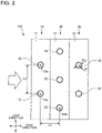
- Fig. 2 is a cross-sectional view showing a configuration of some components of a heat exchanger 100 according to a modification of Embodiment 1.
- Fig. 2 shows a configuration of the heat exchanger 100 as sectioned along the plane perpendicular to the direction in which the first heat transfer pipes 12 extend.
- the heat exchanger 100 of the present modification differs from the heat exchanger 100 shown in Fig. 1 in that the heat exchanger 100 of the present modification includes another second heat exchange unit 30 located further leeward than the second heat exchange unit 20.
- the second heat exchange unit 30 includes a plurality of second fins 31 and a plurality of second heat transfer pipes 32 each passing through the plurality of second fins 31.
- each of the plurality of second fins 31 has a rectangular flat-plate shape.
- Each of the plurality of second fins 31 is placed parallel to the first fins 11 and the second fins 21 and perpendicular to a direction in which the second heat transfer pipes 32 extend.
- the plurality of second fins 31 are provided parallel to each other at regular placement pitches in a direction perpendicular to a surface of paper of Fig. 2 , that is, the direction in which the first heat transfer pipes 12 extend.
- a gap between two second fins 31 adjacent to each other serves as an air passageway.
- each of the first fins 11, each of the second fins 21, and each of the second fins 31 are separate components.
- at least two of the first fin 11, the second fin 21, and the second fin 31 may be integrally formed.
- Each of the plurality of second heat transfer pipes 32 extends in the direction parallel to the direction in which the first heat transfer pipes 12 extend.
- the plurality of second heat transfer pipes 32 are arrayed at step pitches L2 in one row in the step direction of the heat exchanger 100.
- Each of the step pitches L2 is equal to a step pitch between first heat transfer pipes 12 and a step pitch between second heat transfer pipes 22.
- the plurality of second heat transfer pipes 32 constitute a third row of heat transfer pipes as counted from the windward side in the heat exchanger 100.
- the plurality of first heat transfer pipes 12, the plurality of second heat transfer pipes 22, and the plurality of second heat transfer pipes 32 are arrayed at row pitches L1 in the row direction of the heat exchanger 100.
- Each of the plurality of second heat transfer pipes 32 is a circular pipe having an outer diameter Do that is equal to the outer diameter of a first heat transfer pipe 12 and the outer diameter of a second heat transfer pipe 22. Further, each of the plurality of second heat transfer pipes 32 is a circular pipe having a wall thickness tP that is equal to the wall thickness of a first heat transfer pipe 12 and the wall thickness of a second heat transfer pipe 22.
- the respective wall thicknesses tP of the first heat transfer pipes 12, the second heat transfer pipes 22, and the second heat transfer pipes 32 each range, for example, from 0.1 to 0.4 mm. Note, however, that the respective wall thicknesses of the first heat transfer pipes 12, the second heat transfer pipes 22, and the second heat transfer pipes 32 may be each less than 0.1 mm or may be each greater than 0.4 mm.
- the first heat transfer pipes 12, the second heat transfer pipes 22, and the second heat transfer pipes 32 may be subjected to pipe expanding.
- the respective outer diameters Do of the first heat transfer pipes 12, the second heat transfer pipes 22, and the second heat transfer pipes 32 may of course be specified by outer diameters after pipe expanding.
- the following describes heat exchanger performance and cost performance in a case in which the outer diameters Do, the row pitches L1, the step pitches L2, and the wall thicknesses tP of the heat transfer pipes of the heat exchanger 100 are varied.
- Table 1 is a table showing effects exerted on the intra-pipe volume V, the extra-pipe heat transfer coefficient ⁇ o, the ventilation resistance ⁇ P, the extra-pipe heat transfer area Ao, and the heat exchanger weight M in a case in which the outer diameters Do, the row pitches L1, the step pitches L2, and the wall thicknesses tP of the heat transfer pipes of the heat exchanger 100 according to the present embodiment are varied. It should be noted, in Table 1, when each of the parameters, namely the outer diameters Do, the row pitches L1, the step pitches L2, and the wall thicknesses tP of the heat transfer pipes, are varied, the other parameters are fixed.
- the intra-pipe volume V [m 3 ] is a value obtained by multiplying the cross-sectional area of an interior channel of one heat transfer pipe by the length of the heat transfer pipe.
- the extra-pipe heat transfer coefficient ⁇ o [W/m 2 ⁇ K] is the proportion of the amount of heat that is transferred between an outer wall surface of a heat transfer pipe and air.
- the ventilation resistance ⁇ P [Pa] is a pressure loss of air passing through the heat exchanger 100.
- the extra-pipe heat transfer area Ao [m 2 ] is the gross area of the respective outer wall surfaces of the heat transfer pipes of the heat exchanger 100.
- the heat exchanger weight M [kg] is the weight (core weight) of a heat exchange core unit of the heat exchanger 100 and the heat exchange core unit is formed by the heat transfer pipes and the fins.
- the extra-pipe heat transfer coefficient ⁇ o decreases, so that energy-saving effectiveness decreases because of lack of heat transfer performance. Accordingly, for improving the heat transfer performance, it is necessary to increase the extra-pipe heat transfer area Ao by increasing the row pitch L1 or to increase the extra-pipe heat transfer coefficient ⁇ o by reducing the row pitch L1 and increase the extra-pipe heat transfer area Ao by increasing the number of rows of the heat transfer pipes.
- the amount of use of the fins or the heat transfer pipes increases, so that there is a possibility that cost performance, that is, the heat exchange performance of the heat exchanger 100 per unit weight, may decrease.
- cost performance that is, the heat exchange performance of the heat exchanger 100 per unit weight
- the wall thickness tP of each of the heat transfer pipes is increased for the purpose of reducing the intra-pipe volume V, that is, the amount of refrigerant charge
- the amount of use of the heat transfer pipes increases, so that there is a possibility that cost performance may similarly decrease.
- the heat transfer pipes may include first heat transfer pipes 12, second heat transfer pipes 22, and second heat transfer pipes 32.
- the fins may include first fins 11, second fins 21, and second fins 31.
- the area A is an area represented by the product L1 ⁇ L2 of a row pitch L1 and a step pitch L2.
- the area A is equivalent to the area of each fin per heat transfer pipe.
- the area B is an area represented by ((Do - 2 ⁇ tP)/2) 2 ⁇ ⁇ using the outer diameter Do and wall thickness tP of each of the heat transfer pipes.
- the area B is equivalent to the cross-sectional area of an interior channel of one heat transfer pipe.
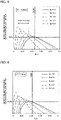
- the horizontal axis of the graph represents the area ratio B/A of the area B to the area A.
- the area ratio B/A represents, as an area ratio, the density at which the heat transfer pipes are placed through the fins.
- a relationship between the area ratio B/A and the intra-pipe volume V is described here.
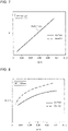
- Fig. 7 is a graph showing a relationship between the area ratio B/A and the intra-pipe volume V in the heat exchanger 100 according to Embodiment 1.
- the intra-pipe volume V decreases as the area ratio B/A decreases.
- the extra-pipe heat exchange performance is (Extra-pipe Heat Transfer Area Ao ⁇ Extra-pipe Heat Transfer Coefficient ⁇ o)/ ⁇ P.
- Extra-pipe Heat Transfer Area Ao ⁇ Extra-pipe Heat Transfer Coefficient ⁇ o is the extra-pipe heat transfer performance.
- Fig. 8 is a graph showing a relationship between the area ratio B/A and the extra-pipe heat transfer performance (Ao ⁇ ⁇ ) in the heat exchanger 100 according to Embodiment 1.
- the area ratio B/A increases, the heat transfer pipes are located closer to each other and thermal conductivity improves, so that the extra-pipe heat transfer performance (Ao ⁇ ⁇ ) increases.
- a comparison made at identical area ratios B/A shows that the extra-pipe heat transfer performance (Ao ⁇ ⁇ ) increases as the outer diameter Do of each of the heat transfer pipes decreases.
- a reason for this is that the heat transfer pipes are located closer to each other as the outer diameter Do of each of the heat transfer pipes decreases.
- Fig. 9 is a graph showing a relationship between the area ratio B/A and the ventilation resistance ⁇ P in the heat exchanger 100 according to Embodiment 1.
- the heat transfer pipes are located closer to each other and resistance to the flow of air passing through the heat exchanger 100 increases, so that the ventilation resistance ⁇ P increases.
- the heat transfer pipes are located to closer to each other as the outer diameter Do of each of the heat transfer pipes decreases, with the same area ratio B/A.
- Fig. 10 is a graph showing a relationship between the area ratio B/A and the heat exchanger weight M in the heat exchanger 100 according to Embodiment 1.
- the value of the weight (core weight) of the heat exchanger 100 has a positive correlation with the amount of material of the heat exchanger 100 to be used and the manufacturing cost of the heat exchanger 100. For this reason, the value of Extra-pipe Heat Exchange Performance/Weight represented by the vertical axis of the graph in each of Figs. 3 to 6 is equivalent to the cost performance of the heat exchanger 100.
- the area ratio B/A decreases, the number of heat transfer pipes that are mounted in the heat exchanger 100 decreases, so that the heat exchanger weight M decreases.
- Fig. 11 is a graph showing a relationship between the area ratio B/A and the extra-pipe heat exchange performance in the heat exchanger 100 according to Embodiment 1.
- Fig. 12 is a graph showing a relationship between the area ratio B/A and the extra-pipe heat exchange performance per unit weight in the heat exchanger 100 according to Embodiment 1.
- Fig. 12 is a graph showing a relationship between the area ratio B/A and the extra-pipe heat
- the heat exchanger weight M increases, so that the extra-pipe heat exchange performance per unit weight has a lower gradient in a region in which the area ratio B/A is high.
- the rate of change in the ventilation resistance ⁇ P increases, so that the extra-pipe heat exchange performance per unit weight to the area ratio B/A having a maximum value is lower.
- the maximum value of the extra-pipe heat exchange performance ((Ao ⁇ ⁇ o)/ ⁇ P) increases as the outer diameter Do of each of the heat transfer pipes decreases.
- Figs. 3 to 6 vary in value of the wall thickness tP from one another.
- Fig. 3 is a graph showing a case in which the wall thickness tP is 0.1 mm.
- Fig. 4 is a graph showing a case in which the wall thickness tP is 0.2 mm.
- Fig. 5 is a graph showing a case in which the wall thickness tP is 0.3 mm.
- Fig. 6 is a graph showing a case in which the wall thickness tP is 0.4 mm.
- the extra-pipe heat exchange performance of the heat exchanger 100 according to the present embodiment per unit weight as shown in Figs. 3 to 6 is calculated by the following method.
- Nu is a Nusselt number and Re is a Reynolds number.
- Pr is a Prandtl number
- ⁇ a is the thermal conductivity of air
- v is the kinematic viscosity of air.
- Pr 0.72
- ⁇ a 0.0261 [W/m ⁇ K]
- v 0.000016 [m 2 /s].
- C 1 and C 2 are constants
- N L is the number of rows of the heat transfer pipes.
- De 4 ⁇ V c / A o
- V c [m 3 ] is a free flow volume
- F P [m] is a fin pitch
- t F [m] is the thickness of each of the fins
- d c [m] is a fin collar outer diameter
- Q air [m 3 /s] is the flow rate of air flowing into the heat exchanger
- EH is the overall height of the heat exchanger in the step direction
- EL is the overall height of the heat exchanger in a direction in which the fins are stacked.
- ⁇ fin efficiency and ⁇ a is an air-side heat transfer coefficient.
- Ao [m 2 ] is the air-side total heat transfer area of the heat exchanger
- a p [m 2 ] is the air-side pipe heat transfer area of the heat exchanger
- a F [m 2 ] is the air-side fin heat transfer area of the heat exchanger
- a con [m 2 ] is the area of contact between the heat transfer pipes and the fins.
- Ao, A p , A F , and A con are values that can be calculated once the dimensions dependent on the shape of the heat exchanger, namely the number N L of rows of heat transfer pipes, the number N D of steps of heat transfer pipes, the number N F of fins, the row pitch L1, the step pitch L2, the fin pitch F P , the fin thickness t F , and the outer diameter Do of each of the heat transfer pipes, are determined.
- the contact heat transfer coefficient ⁇ c between the heat transfer pipes and the fins of the heat exchanger is constant.
- d F [m] is a fin equivalent diameter and ⁇ F [W/m ⁇ K] is the thermal conductivity of the fins.
- f is a coefficient of friction loss
- p is the density of air
- C 3 and C4 are constants.
- the constants C 1 , C 2 , C 3 , and C 4 which are used in the Nusselt number Nu and a coefficient of flow loss f, are set to represent the thermal conductivity ⁇ a and ventilation resistance ⁇ P of the fins of a heat exchanger of a commercially widely-distributed common air-conditioning apparatus.
- the extra-pipe heat exchange performance of the heat exchanger 100 according to the present embodiment per unit weight as shown in Figs. 3 to 6 is calculated under the following conditions.
- a performance calculation is performed under the following calculation conditions.
- the other parameters are similar to the aforementioned calculation conditions.
- the calculation conditions of the comparative example are conditions under which the intra-pipe volume is smallest in Patent Literature 1 ( Japanese Unexamined Patent Application Publication No. 2013-92306 ).
- Extra-pipe Heat Exchange Performance/Weight [Ratio] exceeds 100% and the area ratio B/A falls below that of the comparative example, provided 0.013 ⁇ B/A ⁇ 0.043.
- the area ratio B/A of the comparative example is expressed by Formula (3) below as a function of the wall thickness tP.
- Area Ratio Function of Comparative Example H tP 0.0076 ⁇ tP 2 ⁇ 0.0417 ⁇ tP + 0.0574
- the upper limit function F (Do, tP) is an approximate expression calculated, for example, by a logarithmic approximation of the method of least squares after obtaining, for each wall thickness tP and each outer diameter Do, an upper limit value of the range of numerical values of the area ratio B/A in which Extra-pipe Heat Exchange Performance/Weight [Ratio] exceeds 100% and the area ratio B/A can fall below that of the comparative example.
- the lower limit function G (Do, tP) is an approximate expression calculated, for example, by a power approximation of the method of least squares after obtaining, for each wall thickness tP and each outer diameter Do, an upper limit value of the range of numerical values of the area ratio B/A in which Extra-pipe Heat Exchange Performance/Weight [Ratio] exceeds 100% and the area ratio B/A can fall below that of the comparative example.
- the area ratio function H (tP) of the comparative example is an approximate expression calculated, for example, by a power approximation of the method of least squares after obtaining a value of the area ratio B/A of the comparative example for each wall thickness tP.
- Figs. 13 to 16 are each a graph showing a relationship between the outer diameter Do of each of the heat transfer pipes and the area ratio B/A in the heat exchanger 100 according to Embodiment 1.
- the vertical axis of the graph represents the area ratio B/A of the area B to the area A.
- the horizontal axis of the graph represents the outer diameter Do of each of the heat transfer pipes.
- Figs. 13 to 16 vary in value of the wall thickness tP from one another.
- Fig. 13 is a graph showing a case in which the wall thickness tP is 0.1 mm.
- Fig. 14 is a graph showing a case in which the wall thickness tP is 0.2 mm.
- Fig. 15 is a graph showing a case in which the wall thickness tP is 0.3 mm.
- Fig. 16 is a graph showing a case in which the wall thickness tP is 0.4 mm.
- Extra-pipe Heat Exchange Performance/Weight [Ratio] exceeds 100% and the area ratio B/A can fall below that of the comparative example, provided the outer diameter Do and the area ratio B/A fall within the range greater than or equal to "B/A LOWER LIMIT", less than or equal to "B/A UPPER LIMIT", and less than "B/A COMPARATIVE EXAMPLE” and the outer diameter Do falls within the range of Do ⁇ 5.5 mm. That is, the intra-pipe volume V can be made smaller than that of the comparative example, and the cost performance of the heat exchanger 100 can be made higher than that of the comparative example.
- the heat exchanger 100 can achieve both improvement in cost performance and a reduction in total value of GWP through a reduction in amount of refrigerant charge. As a result, this makes it possible to reduce the amount of refrigerant charge while improving energy-saving effectiveness in a refrigeration cycle apparatus including the heat exchanger 100.
- the foregoing calculation conditions of the heat exchanger 100 according to the present embodiment correspond to cooling rated conditions of an air-conditioning apparatus serving as an example of a refrigeration cycle apparatus. This makes it possible to, under the cooling rated conditions of an air-conditioning apparatus, reduce the amount of refrigerant charge while improving energy-saving effectiveness. It should be noted that even under other conditions such as cooling intermediate conditions, heating rated conditions, and heating intermediate conditions of an air-conditioning apparatus serving as an example of a refrigeration cycle apparatus, the heat exchanger 100 according to the present embodiment brings about effects that are similar to those brought about under the cooling rated conditions.
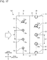
- FIG. 17 is a cross-sectional view showing a configuration of some components of a heat exchanger 100 according to the present embodiment. As with Fig. 1 , Fig. 17 shows a configuration of the heat exchanger 100 as sectioned along the plane perpendicular to the direction in which the first heat transfer pipes 12 extend. Constituent elements having the same functions and workings as those of Embodiment 1 are given the same reference signs, and a description of such constituent elements is omitted.
- each of the plurality of first heat transfer pipes 12 is a circular pipe having a wall thickness tP that is equal to the wall thickness of a second heat transfer pipe 22.
- Fig. 18 is a cross-sectional view showing a configuration of some components of a heat exchanger 100 according to a modification of the present embodiment.
- a step pitch L2a between first heat transfer pipes 12 of the first heat exchange unit 10 located furthest windward is greater than a step pitch L2b between second heat transfer pipes 22 of the second heat exchange unit 20 (L2a > L2b).
- the outer diameter Do of each of the first heat transfer pipes 12 is identical to the outer diameter Do of each of the second heat transfer pipes 22.
- each of the plurality of first heat transfer pipes 12 is a circular pipe having a wall thickness tP that is equal to the wall thickness of a second heat transfer pipe 22.
- the heat exchanger 100 further includes a plurality of heat exchange units, arrayed along the direction of airflow, each of which has one or more of the plurality of heat transfer pipes.
- the plurality of heat exchange units include a first heat exchange unit 10 located furthest windward and at least one second heat exchange unit 20 located further leeward than the first heat exchange unit 10.
- a value of B/A in the first heat exchange unit 10 is smaller than a value of B/A in the at least one second heat exchange unit 20.
- frost easily forms, as a great temperature difference between the first fins 11 or the first heat transfer pipes 12 and air results in an increased amount of heat that is exchanged.
- the foregoing configuration makes it possible to make the first heat exchange unit 10 lower in heat exchange performance than the second heat exchange unit 20. This makes it possible to inhibit the formation of frost in the first heat exchange unit 10 and therefore makes it possible to prevent an air trunk of the first heat exchange unit 10 from being closed by an increased amount of frost that is formed. This makes it possible to improve cost performance while reducing deterioration in ventilation performance of the heat exchanger 100.
- FIG. 19 is a refrigerant circuit diagram showing a configuration of a refrigeration cycle apparatus 200 according to Embodiment 3.
- an air-conditioning apparatus is an example of the refrigeration cycle apparatus 200.
- the refrigeration cycle apparatus 200 includes a refrigeration cycle circuit 50 through which refrigerant circulates.
- the refrigeration cycle circuit 50 is configured such that a compressor 51, a four-way valve 52, an outdoor heat exchanger 53, an expansion valve 54, and an indoor heat exchanger 55 are connected in a circular pattern via refrigerant pipes.
- the refrigeration cycle apparatus 200 includes an outdoor fan 56 configured to supply air to the outdoor heat exchanger 53 and an indoor fan 57 configured to supply air to the indoor heat exchanger 55.
- the compressor 51 is driven so that a refrigeration cycle is executed in which the refrigerant circulates through the refrigeration cycle circuit 50 while the refrigerant changes its phase.
- the outdoor heat exchanger 53 allows the air supplied by the outdoor fan 56 and the refrigerant, which is an inner fluid, to exchange heat with each other.
- the indoor heat exchanger 55 allows the air supplied by the indoor fan 57 and the refrigerant, which is an inner fluid, to exchange heat with each other.
- the heat exchanger 100 of Embodiment 1 or 2 is used as at least either the outdoor heat exchanger 53 or the indoor heat exchanger 55.
- the refrigeration cycle apparatus 200 includes an outdoor unit 110 and an indoor unit 120 as heat exchange units.
- the outdoor unit 110 houses the compressor 51, the four-way valve 52, the outdoor heat exchanger 53, the expansion valve 54, and the outdoor fan 56.
- the indoor unit 120 houses the indoor heat exchanger 55 and the indoor fan 57.
- the outdoor unit 110 and the indoor unit 120 are connected to each other via a gas pipe 130 and a liquid pipe 140, which are some of the refrigerant pipes.
- the refrigeration cycle apparatus 200 Operation of the refrigeration cycle apparatus 200 is described by describing cooling operation as an example.
- the four-way valve 52 is switched such that refrigerant discharged from the compressor 51 flows into the outdoor heat exchanger 53.
- the high-pressure gas refrigerant discharged from the compressor 51 flows into the outdoor heat exchanger 53 via the four-way valve 52.
- the outdoor heat exchanger 53 operates as a condenser. That is, the outdoor heat exchanger 53 allows refrigerant circulating through inside and outdoor air supplied by the outdoor fan 56 to exchange heat with each other, so that the refrigerant transfers heat of condensation to the outdoor air. This causes the gas refrigerant having flowed into the outdoor heat exchanger 53 to condense into high-pressure liquid refrigerant.
- the liquid refrigerant having flowed out of the outdoor heat exchanger 53 is decompressed by the expansion valve 54 into low-pressure two-phase refrigerant.
- the two-phase refrigerant having flowed out of the expansion valve 54 flows into the indoor heat exchanger 55 via the liquid pipe 140.
- the indoor heat exchanger 55 operates as an evaporator. That is, the indoor heat exchanger 55 allows refrigerant circulating through inside and indoor air supplied by the indoor fan 57 to exchange heat with each other, so that the refrigerant removes heat of evaporation from the indoor air. This causes the two-phase refrigerant having flowed into the indoor heat exchanger 55 to evaporate into low-pressure gas refrigerant.
- the indoor air having passed through the indoor heat exchanger 55 is cooled by exchanging heat with the refrigerant.
- the gas refrigerant having flowed out of the indoor heat exchanger 55 is suctioned into the compressor 51 via the gas pipe 130 and the four-way valve 52.
- the gas refrigerant suctioned into the compressor 51 is compressed into high-pressure gas refrigerant.
- the refrigeration cycle described above is continuously and repeatedly executed.
- a direction of refrigerant flow is switched by the four-way valve 52 such that the outdoor heat exchanger 53 operates as an evaporator and the indoor heat exchanger 55 operates as a condenser.
- the refrigeration cycle apparatus 200 includes the heat exchanger 100 of Embodiment 1 or 2. This configuration allows the refrigeration cycle apparatus 200 to achieve both a reduction in total value of GWP and improvement in energy-saving effectiveness.
- Embodiments 1 to 3 and the modifications described above may be combined with each other.
Landscapes
- Engineering & Computer Science (AREA)
- Physics & Mathematics (AREA)
- Thermal Sciences (AREA)
- Mechanical Engineering (AREA)
- General Engineering & Computer Science (AREA)
- Geometry (AREA)
- Heat-Exchange Devices With Radiators And Conduit Assemblies (AREA)
- Compression-Type Refrigeration Machines With Reversible Cycles (AREA)
Abstract
Description
- The present disclosure relates to a heat exchanger including a plurality of fins and a plurality of heat transfer pipes each extending in a direction intersecting the plurality of fins and to a refrigeration cycle apparatus including the same.
-
Patent Literature 1 discloses a heat exchanger including a plurality of fins arranged parallel to each other to form a flow passage of gas and heat transfer pipes each passing through the plurality of fins and through which a medium that exchanges heat with the gas flows. The plurality of fins each have a plurality of through-holes and the heat transfer pipes are fitted separately in the plurality of respective through-holes. The plurality of through-holes are provided at equal intervals along a step direction perpendicular to both a direction in which the plurality of fins are arranged and a direction of flow of the gas, and are provided in a plurality of rows along a row direction parallel to the direction of flow of the gas. - Patent Literature 1:
Japanese Unexamined Patent Application Publication No. 2013-92306 - The heat exchanger of
Patent Literature 1 is a part of a refrigeration cycle apparatus such as an air-conditioning apparatus. There has recently been a demand for a reduction in amount of refrigerant charge to reduce the total value of GWP of a refrigeration cycle apparatus. A possible way of reducing the amount of refrigerant charge in a refrigeration cycle apparatus is to reduce the inner capacity of each of the heat transfer pipes of the heat exchanger by reducing the pipe diameter of each of the heat transfer pipes. However, reducing the pipe diameter of each of the heat transfer pipes usually causes a decrease in heat transfer performance of the heat exchanger. For this reason, to maintain the heat transfer performance of the heat exchanger while reducing the pipe diameter of each of the heat transfer pipes, it is necessary to narrow the intervals at which the fins are placed and increase the number of rows of the heat transfer pipes. Meanwhile, narrowing the intervals at which the fins are placed and increasing the number of rows of the heat transfer pipes result in deterioration in ventilation performance of the heat exchanger. That is, there is a trade-off between heat transfer performance and ventilation performance in a heat exchanger whose heat transfer pipes each have a reduced inner capacity. Heat transfer performance and ventilation performance both affect the heat exchanger performance of a heat exchanger. Accordingly, it has been undesirably difficult to improve the heat exchanger performance of a heat exchanger while reducing the inner capacity of each of the heat transfer pipes. - The present disclosure has been made to solve such a problem, and has as an object to provide a heat exchanger that makes it possible to improve the heat exchanger performance of the heat exchanger while reducing the inner capacity of heat transfer pipes and a refrigeration cycle apparatus including the same.
- A heat exchanger according to an embodiment of the present disclosure includes a plurality of fins arranged in parallel to each other and a plurality of heat transfer pipes each extending in a direction intersecting the plurality of fins. In a plane perpendicular to a direction in which the plurality of heat transfer pipes extend, the plurality of heat transfer pipes are placed in a plurality of rows in a row direction that is along a direction of airflow at a row pitch L1. In the plane, the plurality of heat transfer pipes are placed in a plurality of steps in a step direction perpendicular to the row direction at a step pitch L2. Where an outer diameter of each of the plurality of heat transfer pipes is defined as Do, a wall thickness of a portion having a smallest distance between an outer wall surface and an inner wall surface of each of the plurality of heat transfer pipes is defined as tP, an area represented by a numerical expression of L1 × L2 is defined as A, and an area represented by a numerical expression of ((Do - 2 × tP)/2)2 × π is defined as B, a relation of Do < 5.5 mm, a relation of (0.0219 × tP2 - 0.0185 × tP + 0.0043) × In (Do) + (1.6950 × tP2 + 1.8455 × tP + 1.5416) ≤ B/A ≤ (0.2076 × tP2 - 0.1480 × tP + 0.0545) × Do ^ (-0.0021 × tP2 - 0.0528 × tP + 0.0164), and a relation of B/A < 0.0076 × tP2 - 0.0417 × tP + 0.0574 are satisfied.
- A refrigeration cycle apparatus according to another embodiment of the present disclosure includes the heat exchanger according to an embodiment of the present disclosure.
- An embodiment of the present disclosure makes it possible to improve the heat exchanger performance of a heat exchanger while reducing the inner capacity of heat transfer pipes.
-
- [
Fig. 1] Fig. 1 is a cross-sectional view showing a configuration of some components of aheat exchanger 100 according toEmbodiment 1. - [
Fig. 2] Fig. 2 is a cross-sectional view showing a configuration of some components of aheat exchanger 100 according to a modification ofEmbodiment 1. - [
Fig. 3] Fig. 3 is a graph showing a relationship between the area ratio of heat transfer pipes to fins and extra-pipe heat exchange performance per unit weight in theheat exchanger 100 according toEmbodiment 1 for each outer diameter Do of the heat transfer pipes. - [
Fig. 4] Fig. 4 is a graph showing a relationship between the area ratio of heat transfer pipes to fins and extra-pipe heat exchange performance per unit weight in theheat exchanger 100 according toEmbodiment 1 for each outer diameter Do of the heat transfer pipes. - [
Fig. 5] Fig. 5 is a graph showing a relationship between the area ratio of heat transfer pipes to fins and extra-pipe heat exchange performance per unit weight in theheat exchanger 100 according toEmbodiment 1 for each outer diameter Do of the heat transfer pipes. - [
Fig. 6] Fig. 6 is a graph showing a relationship between the area ratio of heat transfer pipes to fins and extra-pipe heat exchange performance per unit weight in theheat exchanger 100 according toEmbodiment 1 for each outer diameter Do of the heat transfer pipes. - [
Fig. 7] Fig. 7 is a graph showing a relationship between the area ratio B/A and the intra-pipe volume V in theheat exchanger 100 according toEmbodiment 1. - [
Fig. 8] Fig. 8 is a graph showing a relationship between the area ratio B/A and the extra-pipe heat transfer performance (Ao × αο) in theheat exchanger 100 according toEmbodiment 1. - [
Fig. 9] Fig. 9 is a graph showing a relationship between the area ratio B/A and the ventilation resistance ΔP in theheat exchanger 100 according toEmbodiment 1. - [
Fig. 10] Fig. 10 is a graph showing a relationship between the area ratio B/A and the heat exchanger weight M in theheat exchanger 100 according toEmbodiment 1. - [
Fig. 11] Fig. 11 is a graph showing a relationship between the area ratio B/A and the extra-pipe heat exchange performance in theheat exchanger 100 according toEmbodiment 1. - [
Fig. 12] Fig. 12 is a graph showing a relationship between the area ratio B/A and the extra-pipe heat exchange performance per unit weight in theheat exchanger 100 according toEmbodiment 1. - [
Fig. 13] Fig. 13 is a graph showing a relationship between the outer diameter Do of each heat transfer pipe and the area ratio B/A in theheat exchanger 100 according toEmbodiment 1. - [
Fig. 14] Fig. 14 is a graph showing a relationship between the outer diameter Do of each heat transfer pipe and the area ratio B/A in theheat exchanger 100 according toEmbodiment 1. - [
Fig. 15] Fig. 15 is a graph showing a relationship between the outer diameter Do of each heat transfer pipe and the area ratio B/A in theheat exchanger 100 according toEmbodiment 1. - [
Fig. 16] Fig. 16 is a graph showing a relationship between the outer diameter Do of each heat transfer pipe and the area ratio B/A in theheat exchanger 100 according toEmbodiment 1. - [
Fig. 17] Fig. 17 is a cross-sectional view showing a configuration of some components of aheat exchanger 100 according toEmbodiment 2. - [
Fig. 18] Fig. 18 is a cross-sectional view showing a configuration of some components of aheat exchanger 100 according to a modification ofEmbodiment 2. - [
Fig. 19] Fig. 19 is a refrigerant circuit diagram showing a configuration of arefrigeration cycle apparatus 200 according toEmbodiment 3. - A heat exchanger according to
Embodiment 1 is described.Fig. 1 is a cross-sectional view showing a configuration of some components of aheat exchanger 100 according toEmbodiment 1.Fig. 1 shows a configuration of theheat exchanger 100 as sectioned along a plane perpendicular to a direction in which the after-mentioned firstheat transfer pipes 12 extend. Theheat exchanger 100 is used as a heat source side heat exchanger or a load side heat exchanger of a refrigeration cycle apparatus. Theheat exchanger 100 is a cross-fin fin-and-tube heat exchanger that allows refrigerant circulating through the heat transfer pipes and air to exchange heat with each other. A usable example of the refrigerant include a hydrofluorocarbon such as R410, R407C, and R32, isobutane, propane, and carbon dioxide. InFig. 1 , a thick arrow outline with a blank inside represents a direction of airflow. - As shown in
Fig. 1 , theheat exchanger 100 includes, as a plurality of heat exchange units arrayed along the direction of airflow, a firstheat exchange unit 10 located furthest windward and a secondheat exchange unit 20 located further leeward than the firstheat exchange unit 10. - The first
heat exchange unit 10 includes a plurality offirst fins 11 arranged parallel to each other at intervals and a plurality of firstheat transfer pipes 12 each passing through the plurality offirst fins 11 and each extending parallel to each other in a direction intersecting the plurality offirst fins 11. Each of the plurality offirst fins 11 has a rectangular flat-plate shape elongated in one direction. Each of the plurality offirst fins 11 is placed perpendicular to a direction in which the firstheat transfer pipes 12 extend. The plurality offirst fins 11 are provided parallel to each other at regular placement pitches in a direction perpendicular to a surface of paper ofFig. 1 , that is, the direction in which the firstheat transfer pipes 12 extend. A gap between twofirst fins 11 adjacent to each other serves as air passageway through which air circulates. Note here that a direction that is along the direction of airflow in a plane perpendicular to the direction in which the firstheat transfer pipes 12 extend is sometimes referred to as "row direction of theheat exchanger 100" or simply as "row direction". Further, a direction perpendicular to the row direction in the plane is sometimes referred to as "step direction of theheat exchanger 100" or simply as "step direction". The step direction of theheat exchanger 100 is parallel to, for example, a longitudinal direction of each of thefirst fins 11 and a longitudinal direction of each of the after-mentionedsecond fins 21. - Each of the plurality of first
heat transfer pipes 12 extends in the direction perpendicular to the surface of paper ofFig. 1 . The plurality of firstheat transfer pipes 12 are arrayed at regular step pitches L2 in one row in the step direction of theheat exchanger 100. Each of the step pitches can be specified by a distance in the step direction between therespective tube axes 12a of two firstheat transfer pipes 12 adjacent to each other in the step direction. Each of the plurality of firstheat transfer pipes 12 is a circular pipe having an outer diameter Do. Further, each of the plurality of firstheat transfer pipes 12 is a circular pipe having a wall thickness tP of a portion having a smallest distance between an outer wall surface and an inner wall surface. The plurality of firstheat transfer pipes 12 constitute a first row of heat transfer pipes located furthest windward in theheat exchanger 100. - The second
heat exchange unit 20 includes a plurality ofsecond fins 21 arranged parallel to each other at intervals and a plurality of secondheat transfer pipes 22 each passing through the plurality ofsecond fins 21 and each extending parallel to each other in a direction intersecting the plurality ofsecond fins 21. As with thefirst fins 11, each of the plurality ofsecond fins 21 has a rectangular flat-plate shape. Each of the plurality ofsecond fins 21 is placed parallel to thefirst fins 11 and perpendicular to a direction in which the secondheat transfer pipes 22 extend. The plurality ofsecond fins 21 are provided parallel to each other at regular placement pitches in the direction perpendicular to the surface of paper ofFig. 1 , that is, the direction in which the firstheat transfer pipes 12 extend. Each of the plurality ofsecond fins 21 is placed with a displacement of, for example, approximately half a pitch from the corresponding one of the plurality offirst fins 11. A gap between twosecond fins 21 adjacent to each other serves as an air passageway. In the present embodiment, each of thefirst fins 11 and each of thesecond fins 21 are separate components. Alternatively, thefirst fin 11 and thesecond fin 21 may be integrally formed. That is, the firstheat exchange unit 10 and the secondheat exchange unit 20 may share a plurality of fins with each other. - Each of the plurality of second
heat transfer pipes 22 extends in a direction parallel to the direction in which the firstheat transfer pipes 12 extend. The plurality of secondheat transfer pipes 22 are arrayed at step pitches L2 in one row in the step direction of theheat exchanger 100. Each of the step pitches L2 is equal to a step pitch between firstheat transfer pipes 12. Each of the plurality of secondheat transfer pipes 22 is placed with a displacement of, for example, approximately half a pitch from the corresponding one of the plurality of firstheat transfer pipes 12. The plurality of secondheat transfer pipes 22 constitute a second row of heat transfer pipes as counted from a windward side in theheat exchanger 100. The plurality of firstheat transfer pipes 12 and the plurality of secondheat transfer pipes 22 are arrayed at row pitches L1 in the row direction of theheat exchanger 100. Each of the row pitches can be specified by a distance in the row direction between thetube axis 12a of a firstheat transfer pipe 12 and atube axis 22a of a secondheat transfer pipe 22. A row pitch between firstheat transfer pipes 12 in the firstheat exchange unit 10 and a row pitch between secondheat transfer pipes 22 in the secondheat exchange unit 20 can both be considered as L1. Each of the plurality of secondheat transfer pipes 22 is a circular pipe having an outer diameter Do that is equal to the outer diameter of a firstheat transfer pipe 12. Further, each of the plurality of secondheat transfer pipes 22 is a circular pipe having a wall thickness tP that is equal to the wall thickness of a firstheat transfer pipe 12. - The
heat exchanger 100 includes a plurality of refrigerant paths (not illustrated) connected parallel to each other in a flow passage of refrigerant. Each of the plurality of refrigerant paths is formed using one or more firstheat transfer pipes 12, one or more secondheat transfer pipes 22, or a combination of one or more firstheat transfer pipes 12 and one or more secondheat transfer pipes 22. -
Fig. 2 is a cross-sectional view showing a configuration of some components of aheat exchanger 100 according to a modification ofEmbodiment 1. As withFig. 1 ,Fig. 2 shows a configuration of theheat exchanger 100 as sectioned along the plane perpendicular to the direction in which the firstheat transfer pipes 12 extend. As shown inFig. 2 , theheat exchanger 100 of the present modification differs from theheat exchanger 100 shown inFig. 1 in that theheat exchanger 100 of the present modification includes another secondheat exchange unit 30 located further leeward than the secondheat exchange unit 20. - The second
heat exchange unit 30 includes a plurality ofsecond fins 31 and a plurality of secondheat transfer pipes 32 each passing through the plurality ofsecond fins 31. As with thefirst fins 11 and thesecond fins 21, each of the plurality ofsecond fins 31 has a rectangular flat-plate shape. Each of the plurality ofsecond fins 31 is placed parallel to thefirst fins 11 and thesecond fins 21 and perpendicular to a direction in which the secondheat transfer pipes 32 extend. The plurality ofsecond fins 31 are provided parallel to each other at regular placement pitches in a direction perpendicular to a surface of paper ofFig. 2 , that is, the direction in which the firstheat transfer pipes 12 extend. A gap between twosecond fins 31 adjacent to each other serves as an air passageway. In the present embodiment, each of thefirst fins 11, each of thesecond fins 21, and each of thesecond fins 31 are separate components. Alternatively, at least two of thefirst fin 11, thesecond fin 21, and thesecond fin 31 may be integrally formed. - Each of the plurality of second
heat transfer pipes 32 extends in the direction parallel to the direction in which the firstheat transfer pipes 12 extend. The plurality of secondheat transfer pipes 32 are arrayed at step pitches L2 in one row in the step direction of theheat exchanger 100. Each of the step pitches L2 is equal to a step pitch between firstheat transfer pipes 12 and a step pitch between secondheat transfer pipes 22. The plurality of secondheat transfer pipes 32 constitute a third row of heat transfer pipes as counted from the windward side in theheat exchanger 100. The plurality of firstheat transfer pipes 12, the plurality of secondheat transfer pipes 22, and the plurality of secondheat transfer pipes 32 are arrayed at row pitches L1 in the row direction of theheat exchanger 100. Each of the plurality of secondheat transfer pipes 32 is a circular pipe having an outer diameter Do that is equal to the outer diameter of a firstheat transfer pipe 12 and the outer diameter of a secondheat transfer pipe 22. Further, each of the plurality of secondheat transfer pipes 32 is a circular pipe having a wall thickness tP that is equal to the wall thickness of a firstheat transfer pipe 12 and the wall thickness of a secondheat transfer pipe 22. - In the present embodiment, the respective wall thicknesses tP of the first
heat transfer pipes 12, the secondheat transfer pipes 22, and the secondheat transfer pipes 32 each range, for example, from 0.1 to 0.4 mm. Note, however, that the respective wall thicknesses of the firstheat transfer pipes 12, the secondheat transfer pipes 22, and the secondheat transfer pipes 32 may be each less than 0.1 mm or may be each greater than 0.4 mm. - In a process of manufacturing the
heat exchanger 100, the firstheat transfer pipes 12, the secondheat transfer pipes 22, and the secondheat transfer pipes 32 may be subjected to pipe expanding. In this case, the respective outer diameters Do of the firstheat transfer pipes 12, the secondheat transfer pipes 22, and the secondheat transfer pipes 32 may of course be specified by outer diameters after pipe expanding. - The following describes heat exchanger performance and cost performance in a case in which the outer diameters Do, the row pitches L1, the step pitches L2, and the wall thicknesses tP of the heat transfer pipes of the
heat exchanger 100 are varied. - Table 1 is a table showing effects exerted on the intra-pipe volume V, the extra-pipe heat transfer coefficient αo, the ventilation resistance ΔP, the extra-pipe heat transfer area Ao, and the heat exchanger weight M in a case in which the outer diameters Do, the row pitches L1, the step pitches L2, and the wall thicknesses tP of the heat transfer pipes of the
heat exchanger 100 according to the present embodiment are varied. It should be noted, in Table 1, when each of the parameters, namely the outer diameters Do, the row pitches L1, the step pitches L2, and the wall thicknesses tP of the heat transfer pipes, are varied, the other parameters are fixed.[Table 1] Direction of change V αo ΔP Ao M Do Increase + + + - + Decrease - - - + - L1 (Row) Increase Unchanged - + + + Decrease Unchanged + - - - L2 (Step) Increase - - - + - Decrease + + + - + tP Increase - Unchanged Unchanged Unchanged + Decrease + Unchanged Unchanged Unchanged - - The intra-pipe volume V [m3] is a value obtained by multiplying the cross-sectional area of an interior channel of one heat transfer pipe by the length of the heat transfer pipe. The extra-pipe heat transfer coefficient αo [W/m2·K] is the proportion of the amount of heat that is transferred between an outer wall surface of a heat transfer pipe and air. The ventilation resistance ΔP [Pa] is a pressure loss of air passing through the
heat exchanger 100. The extra-pipe heat transfer area Ao [m2] is the gross area of the respective outer wall surfaces of the heat transfer pipes of theheat exchanger 100. The heat exchanger weight M [kg] is the weight (core weight) of a heat exchange core unit of theheat exchanger 100 and the heat exchange core unit is formed by the heat transfer pipes and the fins. - In a case in which the outer diameter Do is reduced and the step pitch L2 is increased for the purpose of reducing the intra-pipe volume V, that is, the amount of refrigerant charge, the extra-pipe heat transfer coefficient αo decreases, so that energy-saving effectiveness decreases because of lack of heat transfer performance. Accordingly, for improving the heat transfer performance, it is necessary to increase the extra-pipe heat transfer area Ao by increasing the row pitch L1 or to increase the extra-pipe heat transfer coefficient αo by reducing the row pitch L1 and increase the extra-pipe heat transfer area Ao by increasing the number of rows of the heat transfer pipes. However, in either case, the amount of use of the fins or the heat transfer pipes increases, so that there is a possibility that cost performance, that is, the heat exchange performance of the
heat exchanger 100 per unit weight, may decrease. Further, in a case in which the wall thickness tP of each of the heat transfer pipes is increased for the purpose of reducing the intra-pipe volume V, that is, the amount of refrigerant charge, the amount of use of the heat transfer pipes increases, so that there is a possibility that cost performance may similarly decrease. For these reasons, it is necessary to appropriately set the outer diameters Do, the row pitches L1, the step pitches L2, and the wall thicknesses tP of the heat transfer pipes of theheat exchanger 100 to achieve both a reduction in the intra-pipe volume V and an increase in cost performance of theheat exchanger 100. - The following describes the extra-pipe heat exchange performance of the
heat exchanger 100 per unit weight. -
Figs. 3 to 6 each show a relationship between the area ratio of heat transfer pipes to fins and extra-pipe heat exchange performance per unit weight in theheat exchanger 100 according toEmbodiment 1 as a ratio to a maximum value at Do = 5.5 mm for each outer diameter Do (Do = 2.0 mm, 3.0 mm, 4.0 mm, 5.0 mm, 5.5 mm) of the heat transfer pipes. - Note here that the heat transfer pipes may include first
heat transfer pipes 12, secondheat transfer pipes 22, and secondheat transfer pipes 32. The fins may includefirst fins 11,second fins 21, andsecond fins 31. The area A is an area represented by the product L1 × L2 of a row pitch L1 and a step pitch L2. The area A is equivalent to the area of each fin per heat transfer pipe. Also, the area B is an area represented by ((Do - 2 × tP)/2)2 × π using the outer diameter Do and wall thickness tP of each of the heat transfer pipes. The area B is equivalent to the cross-sectional area of an interior channel of one heat transfer pipe. - In each of
Figs. 3 to 6 , the horizontal axis of the graph represents the area ratio B/A of the area B to the area A. The area ratio B/A represents, as an area ratio, the density at which the heat transfer pipes are placed through the fins. A relationship between the area ratio B/A and the intra-pipe volume V is described here.Fig. 7 is a graph showing a relationship between the area ratio B/A and the intra-pipe volume V in theheat exchanger 100 according toEmbodiment 1.Fig. 7 shows effects of the area ratio B/A on the intra-pipe volume V in cases where Outer Diameter Do = 3.0 mm and Do = 5.5 mm and Wall Thickness tP = 0.2 mm. As shown inFig. 7 , the intra-pipe volume V decreases as the area ratio B/A decreases. - In each of
Figs. 3 to 6 , the vertical axis of the graph represents the extra-pipe heat transfer performance (Extra-pipe Heat Transfer Performance/Weight) of theheat exchanger 100 per unit weight as a ratio to a maximum value at Do = 5.5 mm. The extra-pipe heat exchange performance is (Extra-pipe Heat Transfer Area Ao × Extra-pipe Heat Transfer Coefficient αo)/ΔP. Extra-pipe Heat Transfer Area Ao × Extra-pipe Heat Transfer Coefficient αo is the extra-pipe heat transfer performance. - A relationship between each of the extra-pipe heat transfer performance, the ventilation resistance ΔP, the heat exchanger weight M, and the extra-pipe heat exchange performance and the area ratio B/A is described here with reference to
Figs. 8 to 12 . -
Fig. 8 is a graph showing a relationship between the area ratio B/A and the extra-pipe heat transfer performance (Ao × αο) in theheat exchanger 100 according toEmbodiment 1.Fig. 8 shows effects of the area ratio B/A on the extra-pipe heat transfer performance (Extra-pipe Heat Transfer Area Ao × Extra-pipe Heat Transfer Coefficient αο) in cases where Outer Diameter Do = 3.0 mm and Do = 5.5 mm and Wall Thickness tP = 0.2 mm. As the area ratio B/A increases, the heat transfer pipes are located closer to each other and thermal conductivity improves, so that the extra-pipe heat transfer performance (Ao × αο) increases. Further, a comparison made at identical area ratios B/A shows that the extra-pipe heat transfer performance (Ao × αο) increases as the outer diameter Do of each of the heat transfer pipes decreases. A reason for this is that the heat transfer pipes are located closer to each other as the outer diameter Do of each of the heat transfer pipes decreases. For example, as shown inFig. 8 , a comparison made at identical area ratios B/A shows that the extra-pipe heat transfer performance (Ao × αο) is higher when Do = 3.0 mm than when Do = 5.5 mm. Further, as an example, in a case in which Area Ratio B/A = 0.06, L1 = L2 = 21.7 mm when Do = 3.0 mm, and L1 = L2 = 39.8 mm when Do = 5.5. That is, the heat transfer pipes are located closer to each other in a case in which Do = 3.0 mm than in a case in which Do = 5.5 mm. -
Fig. 9 is a graph showing a relationship between the area ratio B/A and the ventilation resistance ΔP in theheat exchanger 100 according toEmbodiment 1.Fig. 9 shows effects of the area ratio B/A on the ventilation resistance ΔP in cases where Outer Diameter Do = 3.0 mm and Do = 5.5 mm and Wall Thickness tP = 0.2 mm. As the area ratio B/A increases, the heat transfer pipes are located closer to each other and resistance to the flow of air passing through theheat exchanger 100 increases, so that the ventilation resistance ΔP increases. In particular, the heat transfer pipes are located to closer to each other as the outer diameter Do of each of the heat transfer pipes decreases, with the same area ratio B/A. For this reason, when the area ratio B/A increases, those heat transfer pipes with a smaller outer diameter Do suffer from earlier closure of air trunks through which air circulates and from a higher rate of increase in the ventilation resistance ΔP than do those heat transfer pipes with a large outer diameter Do. -
Fig. 10 is a graph showing a relationship between the area ratio B/A and the heat exchanger weight M in theheat exchanger 100 according toEmbodiment 1.Fig. 10 shows effects of the area ratio B/A on the heat exchanger weight M in cases where Outer Diameter Do = 3.0 mm and Do = 5.5 mm and Wall Thickness tP = 0.2 mm. The value of the weight (core weight) of theheat exchanger 100 has a positive correlation with the amount of material of theheat exchanger 100 to be used and the manufacturing cost of theheat exchanger 100. For this reason, the value of Extra-pipe Heat Exchange Performance/Weight represented by the vertical axis of the graph in each ofFigs. 3 to 6 is equivalent to the cost performance of theheat exchanger 100. As the area ratio B/A decreases, the number of heat transfer pipes that are mounted in theheat exchanger 100 decreases, so that the heat exchanger weight M decreases. -
Fig. 11 is a graph showing a relationship between the area ratio B/A and the extra-pipe heat exchange performance in theheat exchanger 100 according toEmbodiment 1.Fig. 11 shows effects of the area ratio B/A on the extra-pipe heat exchange performance ((Ao × αo)/ΔP) in cases where Outer Diameter Do = 3.0 mm and Do = 5.5 mm and Wall Thickness tP = 0.2 mm. Further,Fig. 12 is a graph showing a relationship between the area ratio B/A and the extra-pipe heat exchange performance per unit weight in theheat exchanger 100 according toEmbodiment 1.Fig. 12 shows effects of the area ratio B/A on the extra-pipe heat exchange performance per unit weight ((Ao × αo)/ΔP/M) in cases where Outer Diameter Do = 3.0 mm and Do = 5.5 mm and Wall Thickness tP = 0.2 mm. As shown inFig. 11 , the characteristic of the extra-pipe heat exchange performance to the area ratio B/A has a maximum value. Further, as shown inFig. 10 , the heat exchanger weight M monotonically increases when the area ratio B/A increases. For this reason, as shown inFig. 12 , the characteristic of the extra-pipe heat exchange performance per unit weight to the area ratio B/A also has a maximum value. Further, as the area ratio B/A increases, the heat exchanger weight M increases, so that the extra-pipe heat exchange performance per unit weight has a lower gradient in a region in which the area ratio B/A is high. Further, as the outer diameter Do of each of the heat transfer pipes decreases, the rate of change in the ventilation resistance ΔP increases, so that the extra-pipe heat exchange performance per unit weight to the area ratio B/A having a maximum value is lower. Further, as shown inFig. 11 , the maximum value of the extra-pipe heat exchange performance ((Ao × αo)/ΔP) increases as the outer diameter Do of each of the heat transfer pipes decreases. - Continued reference is made to
Figs. 3 to 6. Figs. 3 to 6 vary in value of the wall thickness tP from one another.Fig. 3 is a graph showing a case in which the wall thickness tP is 0.1 mm.Fig. 4 is a graph showing a case in which the wall thickness tP is 0.2 mm.Fig. 5 is a graph showing a case in which the wall thickness tP is 0.3 mm.Fig. 6 is a graph showing a case in which the wall thickness tP is 0.4 mm. In general, in a case in which a hydrofluorocarbon is used as refrigerant, the wall thickness tP from approximately 0.15 to 0.2 mm when Do = 5.5 or smaller is often used. - The extra-pipe heat exchange performance of the
heat exchanger 100 according to the present embodiment per unit weight as shown inFigs. 3 to 6 is calculated by the following method. - In general, the heat transfer coefficient αa [W/m2·K] between air and the fins is defined by the following equations.

- Note here that Nu is a Nusselt number and Re is a Reynolds number. Pr is a Prandtl number, λa is the thermal conductivity of air, and v is the kinematic viscosity of air. At ordinary temperatures and pressures, Pr = 0.72, λa = 0.0261 [W/m·K], and v = 0.000016 [m2/s]. Further, C1 and C2 are constants, and NL is the number of rows of the heat transfer pipes.
- The characteristic length De [m] is defined by the following equations.

- Note here that Vc [m3] is a free flow volume, FP [m] is a fin pitch, tF [m] is the thickness of each of the fins, and dc [m] is a fin collar outer diameter.
- The wind velocity U [m/s] based on a free passage volume between fins and the front wind velocity Uf [m/s] of the heat exchanger are defined by the following equations.

- Note here that Qair [m3/s] is the flow rate of air flowing into the heat exchanger, EH is the overall height of the heat exchanger in the step direction, and EL is the overall height of the heat exchanger in a direction in which the fins are stacked.
- In general, the extra-pipe heat transfer coefficient αo is defined by the following equations.

- Note here that η is fin efficiency and αa is an air-side heat transfer coefficient. Ao [m2] is the air-side total heat transfer area of the heat exchanger, Ap [m2] is the air-side pipe heat transfer area of the heat exchanger, AF [m2] is the air-side fin heat transfer area of the heat exchanger, and Acon [m2] is the area of contact between the heat transfer pipes and the fins. Ao, Ap, AF, and Acon are values that can be calculated once the dimensions dependent on the shape of the heat exchanger, namely the number NL of rows of heat transfer pipes, the number ND of steps of heat transfer pipes, the number NF of fins, the row pitch L1, the step pitch L2, the fin pitch FP, the fin thickness tF, and the outer diameter Do of each of the heat transfer pipes, are determined. The contact heat transfer coefficient αc between the heat transfer pipes and the fins of the heat exchanger is constant.
- The fin efficiency η is defined by the following equations.

- Note here that dF [m] is a fin equivalent diameter and λF [W/m·K] is the thermal conductivity of the fins.
- The ventilation resistance ΔP [Pa] is defined by the following equations.

- Note here that f is a coefficient of friction loss, p is the density of air, and C3 and C4 are constants.
- It should be noted that the constants C1, C2, C3, and C4, which are used in the Nusselt number Nu and a coefficient of flow loss f, are set to represent the thermal conductivity αa and ventilation resistance ΔP of the fins of a heat exchanger of a commercially widely-distributed common air-conditioning apparatus.
- The extra-pipe heat exchange performance of the
heat exchanger 100 according to the present embodiment per unit weight as shown inFigs. 3 to 6 is calculated under the following conditions. -
- Dry-bulb temperature of air flowing into heat exchanger 100: 35 degrees Celsius
- Wet-bulb temperature of air flowing into heat exchanger 100: 24 degrees Celsius
- Wind velocity at front of
heat exchanger 100 of air flowing into heat exchanger 100: 1.2 m/sec - Refrigerant: R32
- Outer diameter Do of heat transfer pipe: 2.0 mm to 5.5 mm
- Wall thickness tP of heat transfer pipe: 0.1 mm to 0.4 mm
- Material of heat transfer pipe: copper
- Row pitch L1: 11 mm to 22 mm
- Step pitch L2: 5 mm to 42 mm
- Thickness of fin: 0.10 mm
- Fin pitch FP: 1.50 mm
- Material of fin: aluminum
- Shape of fin: flat fin
- As a comparative example, a performance calculation is performed under the following calculation conditions. The other parameters are similar to the aforementioned calculation conditions. The calculation conditions of the comparative example are conditions under which the intra-pipe volume is smallest in Patent Literature 1 (
Japanese Unexamined Patent Application Publication No. 2013-92306 - Outer diameter Do of heat transfer pipe: 5.5
- Row pitch L1: 20.35 mm
- Step pitch L2: 20.35 mm
- Fin pitch FP: 1.50 mm
- Further, under the calculation conditions of the comparative example, the area ratio B/A is 0.053 in a case in which Wall Thickness tP = 0.1 mm, is 0.049 in a case in which Wall Thickness tP = 0.2 mm, is 0.046 in a case in which Wall Thickness tP = 0.3 mm, and is 0.042 in a case in which Wall Thickness tP = 0.4 mm.
- As shown in
Figs. 3 to 6 , there is a region in which the outer diameter Do of each pipe is less than 5.5 mm, Extra-pipe Heat Exchange Performance/Weight [Ratio] exceeds 100%, and the area ratio B/A can fall below that of the comparative example. That is, if the area ratio B/A falls below that of the comparative example, the intra-pipe volume V can be made smaller than that of the comparative example, and the cost performance of theheat exchanger 100 can be made higher than that of the comparative example. - A range of numerical values of the area ratio B/A in which Extra-pipe Heat Exchange Performance/Weight [Ratio] exceeds 100% and the area ratio B/A can fall below that of the comparative example varies with the outer diameter Do and the wall thickness tP. For example, as shown in
Fig. 4 , in a case where Wall Thickness tP = 0.2 mm and Do = 3.0, Extra-pipe Heat Exchange Performance/Weight [Ratio] exceeds 100% and the area ratio B/A falls below that of the comparative example, provided 0.013 ≤ B/A ≤ 0.043. Further, for example, as shown inFig. 4 , in a case where Wall Thickness tP = 0.2 mm and Do = 4.0, Extra-pipe Heat Exchange Performance/Weight [Ratio] exceeds 100% and the area ratio B/A falls below that of the comparative example, provided 0.023 ≤ B/A ≤ 0.049. Further, for example, as shown inFig. 5 , in a case where Wall Thickness tP = 0.3 mm and Do = 3.0, Extra-pipe Heat Exchange Performance/Weight [Ratio] exceeds 100% and the area ratio B/A falls below that of the comparative example, provided 0.009 ≤ B/A ≤ 0.033. - An upper limit of the range of numerical values of the area ratio B/A in which the outer diameter Do of each pipe is less than 5.5 mm, Extra-pipe Heat Exchange Performance/Weight [Ratio] exceeds 100%, and the area ratio B/A can fall below that of the comparative example, shown in
Figs. 3 to 6 , is expressed by Formula (1) below as a function of the outer diameter Do and the wall thickness tP. Further, a lower limit of the range of numerical values of the area ratio B/A in which Extra-pipe Heat Exchange Performance/Weight [Ratio] exceeds 100% and the area ratio B/A can fall below that of the comparative example, shown inFigs. 3 to 6 , is expressed by Formula (2) below as a function of the outer diameter Do and the wall thickness tP.
- It should be noted that In is a natural logarithm whose base is e.

- Further, the area ratio B/A of the comparative example is expressed by Formula (3) below as a function of the wall thickness tP.

- The upper limit function F (Do, tP) is an approximate expression calculated, for example, by a logarithmic approximation of the method of least squares after obtaining, for each wall thickness tP and each outer diameter Do, an upper limit value of the range of numerical values of the area ratio B/A in which Extra-pipe Heat Exchange Performance/Weight [Ratio] exceeds 100% and the area ratio B/A can fall below that of the comparative example. Further, the lower limit function G (Do, tP) is an approximate expression calculated, for example, by a power approximation of the method of least squares after obtaining, for each wall thickness tP and each outer diameter Do, an upper limit value of the range of numerical values of the area ratio B/A in which Extra-pipe Heat Exchange Performance/Weight [Ratio] exceeds 100% and the area ratio B/A can fall below that of the comparative example. Further, the area ratio function H (tP) of the comparative example is an approximate expression calculated, for example, by a power approximation of the method of least squares after obtaining a value of the area ratio B/A of the comparative example for each wall thickness tP.
- With Formulas (1) to (3) above, a relationship among the outer diameter Do, the area ratio B/A, and the wall thickness tP in which Extra-pipe Heat Exchange Performance/Weight [Ratio] exceeds 100% and the area ratio B/A can fall below that of the comparative example is expressed by Formula (4) below.

- Specific examples of the range of numerical values identified by Formula (4) above under the aforementioned calculation conditions are described here with reference to
Figs. 13 to 16 . -
Figs. 13 to 16 are each a graph showing a relationship between the outer diameter Do of each of the heat transfer pipes and the area ratio B/A in theheat exchanger 100 according toEmbodiment 1. In each ofFigs. 13 to 16 , the vertical axis of the graph represents the area ratio B/A of the area B to the area A. The horizontal axis of the graph represents the outer diameter Do of each of the heat transfer pipes. - In each of
Figs. 13 to 16 , the upper limit function F (Do, tP) is shown as "B/A UPPER LIMIT". Further, the lower limit function G (Do, tP) is shown as "B/A LOWER LIMIT". Further, the area ratio function H (tP) of the comparative example is shown as "B/A COMPARATIVE EXAMPLE".Figs. 13 to 16 vary in value of the wall thickness tP from one another.Fig. 13 is a graph showing a case in which the wall thickness tP is 0.1 mm.Fig. 14 is a graph showing a case in which the wall thickness tP is 0.2 mm.Fig. 15 is a graph showing a case in which the wall thickness tP is 0.3 mm.Fig. 16 is a graph showing a case in which the wall thickness tP is 0.4 mm. - As shown in
Figs. 13 to 16 , at each wall thickness tP, Extra-pipe Heat Exchange Performance/Weight [Ratio] exceeds 100% and the area ratio B/A can fall below that of the comparative example, provided the outer diameter Do and the area ratio B/A fall within the range greater than or equal to "B/A LOWER LIMIT", less than or equal to "B/A UPPER LIMIT", and less than "B/A COMPARATIVE EXAMPLE" and the outer diameter Do falls within the range of Do < 5.5 mm. That is, the intra-pipe volume V can be made smaller than that of the comparative example, and the cost performance of theheat exchanger 100 can be made higher than that of the comparative example. - As noted above, configuring the
heat exchanger 100 such that when Outer Diameter Do < 5.5 mm, Lower Limit Function G (Do, tP) ≤ Area Ratio B/A ≤ Upper Limit Function F (Do, tP) and Area Ratio B/A < Area Ratio Function H (tP) of Comparative Example allows the amount of refrigerant charge to fall below that of the comparative example while allowing Extra-pipe Heat Exchange Performance/Weight [Ratio] to exceed 100%. This in turn makes it possible to improve heat exchanger performance while reducing the inner capacity of each of the heat transfer pipes of theheat exchanger 100. Therefore, theheat exchanger 100 according to the present embodiment can achieve both improvement in cost performance and a reduction in total value of GWP through a reduction in amount of refrigerant charge. As a result, this makes it possible to reduce the amount of refrigerant charge while improving energy-saving effectiveness in a refrigeration cycle apparatus including theheat exchanger 100. - Further, the foregoing calculation conditions of the
heat exchanger 100 according to the present embodiment correspond to cooling rated conditions of an air-conditioning apparatus serving as an example of a refrigeration cycle apparatus. This makes it possible to, under the cooling rated conditions of an air-conditioning apparatus, reduce the amount of refrigerant charge while improving energy-saving effectiveness. It should be noted that even under other conditions such as cooling intermediate conditions, heating rated conditions, and heating intermediate conditions of an air-conditioning apparatus serving as an example of a refrigeration cycle apparatus, theheat exchanger 100 according to the present embodiment brings about effects that are similar to those brought about under the cooling rated conditions. - A heat exchanger according to
Embodiment 2 is described.Fig. 17 is a cross-sectional view showing a configuration of some components of aheat exchanger 100 according to the present embodiment. As withFig. 1 ,Fig. 17 shows a configuration of theheat exchanger 100 as sectioned along the plane perpendicular to the direction in which the firstheat transfer pipes 12 extend. Constituent elements having the same functions and workings as those ofEmbodiment 1 are given the same reference signs, and a description of such constituent elements is omitted. - In the
heat exchanger 100 of the present embodiment, as shown inFig. 17 , the outer diameter Doa of each of the firstheat transfer pipes 12 of the firstheat exchange unit 10 located furthest windward is smaller than the outer diameter Dob of each of the secondheat transfer pipes 22 of the second heat exchange unit 20 (Doa < Dob). A step pitch L2 between firstheat transfer pipes 12 is identical to a step pitch L2 between secondheat transfer pipes 22. Further, each of the plurality of firstheat transfer pipes 12 is a circular pipe having a wall thickness tP that is equal to the wall thickness of a secondheat transfer pipe 22. - In both the first
heat exchange unit 10 and the secondheat exchange unit 20, the relation of Formula (4), which is described above inEmbodiment 1, is satisfied. Further, a value of B/A in the firstheat exchange unit 10 is smaller than a value of B/A in the secondheat exchange unit 20. -
Fig. 18 is a cross-sectional view showing a configuration of some components of aheat exchanger 100 according to a modification of the present embodiment. In theheat exchanger 100 of the present modification, as shown inFig. 18 , a step pitch L2a between firstheat transfer pipes 12 of the firstheat exchange unit 10 located furthest windward is greater than a step pitch L2b between secondheat transfer pipes 22 of the second heat exchange unit 20 (L2a > L2b). The outer diameter Do of each of the firstheat transfer pipes 12 is identical to the outer diameter Do of each of the secondheat transfer pipes 22. Further, each of the plurality of firstheat transfer pipes 12 is a circular pipe having a wall thickness tP that is equal to the wall thickness of a secondheat transfer pipe 22. - In both the first
heat exchange unit 10 and the secondheat exchange unit 20, the relation of Formula (4), which is described above inEmbodiment 1, is satisfied. Further, a value of B/A in the firstheat exchange unit 10 is smaller than a value of B/A in the secondheat exchange unit 20. - As described above, the
heat exchanger 100 according to the present embodiment further includes a plurality of heat exchange units, arrayed along the direction of airflow, each of which has one or more of the plurality of heat transfer pipes. The plurality of heat exchange units include a firstheat exchange unit 10 located furthest windward and at least one secondheat exchange unit 20 located further leeward than the firstheat exchange unit 10. A value of B/A in the firstheat exchange unit 10 is smaller than a value of B/A in the at least one secondheat exchange unit 20. - In general, in the first
heat exchange unit 10 located furthest windward, frost easily forms, as a great temperature difference between thefirst fins 11 or the firstheat transfer pipes 12 and air results in an increased amount of heat that is exchanged. The foregoing configuration makes it possible to make the firstheat exchange unit 10 lower in heat exchange performance than the secondheat exchange unit 20. This makes it possible to inhibit the formation of frost in the firstheat exchange unit 10 and therefore makes it possible to prevent an air trunk of the firstheat exchange unit 10 from being closed by an increased amount of frost that is formed. This makes it possible to improve cost performance while reducing deterioration in ventilation performance of theheat exchanger 100. - A refrigeration cycle apparatus according to
Embodiment 3 is described.Fig. 19 is a refrigerant circuit diagram showing a configuration of arefrigeration cycle apparatus 200 according toEmbodiment 3. In the present embodiment, an air-conditioning apparatus is an example of therefrigeration cycle apparatus 200. As shown inFig. 19 , therefrigeration cycle apparatus 200 includes arefrigeration cycle circuit 50 through which refrigerant circulates. Therefrigeration cycle circuit 50 is configured such that acompressor 51, a four-way valve 52, anoutdoor heat exchanger 53, anexpansion valve 54, and anindoor heat exchanger 55 are connected in a circular pattern via refrigerant pipes. Further, therefrigeration cycle apparatus 200 includes anoutdoor fan 56 configured to supply air to theoutdoor heat exchanger 53 and anindoor fan 57 configured to supply air to theindoor heat exchanger 55. In therefrigeration cycle apparatus 200, thecompressor 51 is driven so that a refrigeration cycle is executed in which the refrigerant circulates through therefrigeration cycle circuit 50 while the refrigerant changes its phase. Theoutdoor heat exchanger 53 allows the air supplied by theoutdoor fan 56 and the refrigerant, which is an inner fluid, to exchange heat with each other. Theindoor heat exchanger 55 allows the air supplied by theindoor fan 57 and the refrigerant, which is an inner fluid, to exchange heat with each other. As at least either theoutdoor heat exchanger 53 or theindoor heat exchanger 55, theheat exchanger 100 ofEmbodiment - The
refrigeration cycle apparatus 200 includes anoutdoor unit 110 and anindoor unit 120 as heat exchange units. Theoutdoor unit 110 houses thecompressor 51, the four-way valve 52, theoutdoor heat exchanger 53, theexpansion valve 54, and theoutdoor fan 56. Theindoor unit 120 houses theindoor heat exchanger 55 and theindoor fan 57. Theoutdoor unit 110 and theindoor unit 120 are connected to each other via agas pipe 130 and aliquid pipe 140, which are some of the refrigerant pipes. - Operation of the
refrigeration cycle apparatus 200 is described by describing cooling operation as an example. For cooling operation, the four-way valve 52 is switched such that refrigerant discharged from thecompressor 51 flows into theoutdoor heat exchanger 53. The high-pressure gas refrigerant discharged from thecompressor 51 flows into theoutdoor heat exchanger 53 via the four-way valve 52. During cooling operation, theoutdoor heat exchanger 53 operates as a condenser. That is, theoutdoor heat exchanger 53 allows refrigerant circulating through inside and outdoor air supplied by theoutdoor fan 56 to exchange heat with each other, so that the refrigerant transfers heat of condensation to the outdoor air. This causes the gas refrigerant having flowed into theoutdoor heat exchanger 53 to condense into high-pressure liquid refrigerant. - The liquid refrigerant having flowed out of the
outdoor heat exchanger 53 is decompressed by theexpansion valve 54 into low-pressure two-phase refrigerant. The two-phase refrigerant having flowed out of theexpansion valve 54 flows into theindoor heat exchanger 55 via theliquid pipe 140. During cooling operation, theindoor heat exchanger 55 operates as an evaporator. That is, theindoor heat exchanger 55 allows refrigerant circulating through inside and indoor air supplied by theindoor fan 57 to exchange heat with each other, so that the refrigerant removes heat of evaporation from the indoor air. This causes the two-phase refrigerant having flowed into theindoor heat exchanger 55 to evaporate into low-pressure gas refrigerant. The indoor air having passed through theindoor heat exchanger 55 is cooled by exchanging heat with the refrigerant. The gas refrigerant having flowed out of theindoor heat exchanger 55 is suctioned into thecompressor 51 via thegas pipe 130 and the four-way valve 52. The gas refrigerant suctioned into thecompressor 51 is compressed into high-pressure gas refrigerant. During cooling operation, the refrigeration cycle described above is continuously and repeatedly executed. Although not described, for heating operation, a direction of refrigerant flow is switched by the four-way valve 52 such that theoutdoor heat exchanger 53 operates as an evaporator and theindoor heat exchanger 55 operates as a condenser. - As described above, the
refrigeration cycle apparatus 200 according to the present embodiment includes theheat exchanger 100 ofEmbodiment refrigeration cycle apparatus 200 to achieve both a reduction in total value of GWP and improvement in energy-saving effectiveness. -
Embodiments 1 to 3 and the modifications described above may be combined with each other. - 10: first heat exchange unit, 11: first fin, 12: first heat transfer pipe, 12a: tube axis, 20: second heat exchange unit, 21: second fin, 22: second heat transfer pipe, 22a: tube axis, 30: second heat exchange unit, 31: second fin, 32: second heat transfer pipe, 50: refrigeration cycle circuit, 51: compressor, 52: four-way valve, 53: outdoor heat exchanger, 54: expansion valve, 55: indoor heat exchanger, 56: outdoor fan, 57: indoor fan, 100: heat exchanger, 110: outdoor unit, 120: indoor unit, 130: gas pipe, 140: liquid pipe, 200: refrigeration cycle apparatus, Do: outer diameter, Doa: outer diameter, Dob: outer diameter, L1: row pitch, L2: step pitch, L2a: step pitch, L2b: step pitch, tP: wall thickness
Claims (3)
- A heat exchanger, comprising:a plurality of fins arranged in parallel to each other; anda plurality of heat transfer pipes each extending in a direction intersecting the plurality of fins,in a plane perpendicular to a direction in which the plurality of heat transfer pipes extend, the plurality of heat transfer pipes being placed in a plurality of rows in a row direction that is along a direction of airflow at a row pitch L1,in the plane, the plurality of heat transfer pipes being placed in a plurality of steps in a step direction perpendicular to the row direction at a step pitch L2,where an outer diameter of each of the plurality of heat transfer pipes is defined as Do,a wall thickness of a portion having a smallest distance between an outer wall surface and an inner wall surface of each of the plurality of heat transfer pipes is defined as tP,an area represented by a numerical expression of L1 × L2 is defined as A, andan area represented by a numerical expression of ((Do - 2 × tP)/2)2 × π is defined as B,a relation of Do < 5.5 mm,a relation of (0.0219 × tP2 - 0.0185 × tP + 0.0043) × In (Do) + (1.6950 × tP2 + 1.8455 × tP + 1.5416) ≤ B/A ≤ (0.2076 × tP2 - 0.1480 × tP + 0.0545) × Do ^ (-0.0021 × tP2 - 0.0528 × tP + 0.0164), anda relation of B/A < 0.0076 × tP2 - 0.0417 × tP + 0.0574being satisfied.
- The heat exchanger of claim 1, further comprising a plurality of heat exchange units, arrayed along the direction of airflow, each of which has one or more of the plurality of heat transfer pipes,wherein the plurality of heat exchange units include a first heat exchange unit located furthest windward and at least one second heat exchange unit located further leeward than the first heat exchange unit, anda value of B/A in the first heat exchange unit is smaller than a value of B/A in the at least one second heat exchange unit.
- A refrigeration cycle apparatus, comprising the heat exchanger of claim 1 or 2.
Applications Claiming Priority (1)
| Application Number | Priority Date | Filing Date | Title |
|---|---|---|---|
| PCT/JP2019/030927 WO2021024387A1 (en) | 2019-08-06 | 2019-08-06 | Heat exchanger and refrigeration cycle apparatus |
Publications (3)
| Publication Number | Publication Date |
|---|---|
| EP4012315A1 true EP4012315A1 (en) | 2022-06-15 |
| EP4012315A4 EP4012315A4 (en) | 2022-08-03 |
| EP4012315B1 EP4012315B1 (en) | 2025-01-22 |
Family
ID=74502567
Family Applications (1)
| Application Number | Title | Priority Date | Filing Date |
|---|---|---|---|
| EP19940370.0A Active EP4012315B1 (en) | 2019-08-06 | 2019-08-06 | Heat exchanger and refrigeration cycle apparatus |
Country Status (6)
| Country | Link |
|---|---|
| US (1) | US11965701B2 (en) |
| EP (1) | EP4012315B1 (en) |
| JP (1) | JP7112168B2 (en) |
| CN (1) | CN114174751B (en) |
| AU (1) | AU2019460046B2 (en) |
| WO (1) | WO2021024387A1 (en) |
Families Citing this family (3)
| Publication number | Priority date | Publication date | Assignee | Title |
|---|---|---|---|---|
| US20240271881A1 (en) * | 2023-02-09 | 2024-08-15 | Raytheon Technologies Corporation | Tube heat exchanger with varying diameters |
| WO2024246993A1 (en) * | 2023-05-26 | 2024-12-05 | 三菱電機株式会社 | Heat exchanger and refrigeration cycle device |
| US20250189234A1 (en) * | 2023-12-11 | 2025-06-12 | Baltimore Aircoil Company, Inc. | Heat exchanger |
Family Cites Families (23)
| Publication number | Priority date | Publication date | Assignee | Title |
|---|---|---|---|---|
| US2006649A (en) * | 1930-12-15 | 1935-07-02 | Modine Mfg Co | Radiator core |
| US5318112A (en) * | 1993-03-02 | 1994-06-07 | Raditech Ltd. | Finned-duct heat exchanger |
| JP3720208B2 (en) | 1999-03-23 | 2005-11-24 | 三菱電機株式会社 | Heat exchanger and air-conditioning refrigeration apparatus using the same |
| JP2001091183A (en) * | 1999-07-21 | 2001-04-06 | Matsushita Refrig Co Ltd | Fin tube type heat exchanger |
| JP2003021485A (en) * | 2001-07-11 | 2003-01-24 | Toshiba Kyaria Kk | Fin tube type heat exchanger |
| US6793012B2 (en) * | 2002-05-07 | 2004-09-21 | Valeo, Inc | Heat exchanger |
| EP1398565A1 (en) * | 2002-09-10 | 2004-03-17 | Siemens Aktiengesellschaft | Horizontally positioned steam generator |
| US6997248B2 (en) * | 2004-05-19 | 2006-02-14 | Outokumpu Oyj | High pressure high temperature charge air cooler |
| JP2006234264A (en) * | 2005-02-24 | 2006-09-07 | Mitsubishi Electric Corp | Finned tube heat exchanger |
| DE102007028332A1 (en) * | 2007-06-15 | 2008-12-18 | Basf Se | A method for feeding a reactor with a fixed catalyst bed comprising at least annular shaped catalyst bodies K. |
| KR20090022840A (en) | 2007-08-31 | 2009-03-04 | 엘지전자 주식회사 | Heat exchanger of refrigeration unit |
| JP5519205B2 (en) | 2008-08-07 | 2014-06-11 | サンデン株式会社 | Heat exchanger and heat pump device using the same |
| JP2011237047A (en) | 2010-04-30 | 2011-11-24 | Daikin Industries Ltd | Heat exchanger of air conditioner |
| JP2013092306A (en) * | 2011-10-26 | 2013-05-16 | Panasonic Corp | Fin tube heat exchanger |
| JP2013245884A (en) * | 2012-05-28 | 2013-12-09 | Panasonic Corp | Fin tube heat exchanger |
| JP2014020756A (en) * | 2012-07-23 | 2014-02-03 | Panasonic Corp | Fin tube heat exchanger, heat pump device and heat transfer fin |
| WO2014147788A1 (en) * | 2013-03-21 | 2014-09-25 | 三菱電機株式会社 | Heat exchanger, refrigeration cycle device, and production method for heat exchanger |
| JP6011481B2 (en) * | 2013-07-12 | 2016-10-19 | 株式会社デンソー | Heat exchanger fins |
| JP6276539B2 (en) * | 2013-08-26 | 2018-02-07 | 三菱重工業株式会社 | HEAT EXCHANGER AND HEAT EXCHANGER MANUFACTURING METHOD |
| JP6180338B2 (en) | 2014-01-29 | 2017-08-16 | ジョンソンコントロールズ ヒタチ エア コンディショニング テクノロジー(ホンコン)リミテッド | Air conditioner |
| JP6575895B2 (en) * | 2015-01-28 | 2019-09-18 | パナソニックIpマネジメント株式会社 | Heat exchanger |
| JP2017166757A (en) | 2016-03-16 | 2017-09-21 | 三星電子株式会社Samsung Electronics Co.,Ltd. | Heat exchanger and air conditioner |
| JP2019138582A (en) * | 2018-02-13 | 2019-08-22 | 株式会社Uacj | Heat exchanger for refrigerator freezer |
-
2019
- 2019-08-06 AU AU2019460046A patent/AU2019460046B2/en active Active
- 2019-08-06 EP EP19940370.0A patent/EP4012315B1/en active Active
- 2019-08-06 CN CN201980098574.8A patent/CN114174751B/en active Active
- 2019-08-06 WO PCT/JP2019/030927 patent/WO2021024387A1/en not_active Ceased
- 2019-08-06 JP JP2021538593A patent/JP7112168B2/en not_active Expired - Fee Related
- 2019-08-06 US US17/615,199 patent/US11965701B2/en active Active
Also Published As
| Publication number | Publication date |
|---|---|
| CN114174751A (en) | 2022-03-11 |
| EP4012315B1 (en) | 2025-01-22 |
| WO2021024387A1 (en) | 2021-02-11 |
| AU2019460046B2 (en) | 2023-11-16 |
| US20220228818A1 (en) | 2022-07-21 |
| JPWO2021024387A1 (en) | 2021-02-11 |
| EP4012315A4 (en) | 2022-08-03 |
| AU2019460046A1 (en) | 2022-02-24 |
| US11965701B2 (en) | 2024-04-23 |
| JP7112168B2 (en) | 2022-08-03 |
| CN114174751B (en) | 2023-10-13 |
Similar Documents
| Publication | Publication Date | Title |
|---|---|---|
| US11009300B2 (en) | Heat exchanger and air-conditioning apparatus | |
| JP6109303B2 (en) | Heat exchanger and refrigeration cycle apparatus | |
| US12228350B2 (en) | Heat exchanger and refrigeration cycle apparatus | |
| US20100205993A1 (en) | Heat exchanger arranged in ceiling-buried air conditioner and ceiling-buried air conditioner | |
| EP3062037B1 (en) | Heat exchanger and refrigeration cycle device using said heat exchanger | |
| EP4012315B1 (en) | Heat exchanger and refrigeration cycle apparatus | |
| WO2015004720A1 (en) | Heat exchanger, and air conditioner | |
| JP4922669B2 (en) | Air conditioner and heat exchanger for air conditioner | |
| JP5608478B2 (en) | Heat exchanger and air conditioner using the same | |
| JP6575895B2 (en) | Heat exchanger | |
| JP5627635B2 (en) | Air conditioner | |
| EP1757869A2 (en) | Heat exchanger for air conditioner having different circuit pattern depending on distance from fan | |
| JP2009127882A (en) | Heat exchanger, indoor unit and air conditioner | |
| CN113646597B (en) | Refrigeration cycle device | |
| JPWO2017208419A1 (en) | Fin tube type heat exchanger and heat pump device provided with the fin tube type heat exchanger | |
| JP2008215737A (en) | Finned tube heat exchanger and refrigeration cycle | |
| CN115298486B (en) | Outdoor unit of air conditioner | |
| JP2006234264A (en) | Finned tube heat exchanger | |
| CN111512099A (en) | Heat Exchangers and Refrigeration Cycle Devices | |
| US20230147134A1 (en) | Heat exchanger and air-conditioning apparatus | |
| WO2017149642A1 (en) | Refrigeration cycle device | |
| CN114440328A (en) | Heat exchanger and refrigeration cycle device provided with same | |
| WO2022215193A1 (en) | Refrigeration cycle device | |
| JPH07332805A (en) | Air conditioner |
Legal Events
| Date | Code | Title | Description |
|---|---|---|---|
| STAA | Information on the status of an ep patent application or granted ep patent |
Free format text: STATUS: THE INTERNATIONAL PUBLICATION HAS BEEN MADE |
|
| PUAI | Public reference made under article 153(3) epc to a published international application that has entered the european phase |
Free format text: ORIGINAL CODE: 0009012 |
|
| STAA | Information on the status of an ep patent application or granted ep patent |
Free format text: STATUS: REQUEST FOR EXAMINATION WAS MADE |
|
| 17P | Request for examination filed |
Effective date: 20220112 |
|
| AK | Designated contracting states |
Kind code of ref document: A1 Designated state(s): AL AT BE BG CH CY CZ DE DK EE ES FI FR GB GR HR HU IE IS IT LI LT LU LV MC MK MT NL NO PL PT RO RS SE SI SK SM TR |
|
| A4 | Supplementary search report drawn up and despatched |
Effective date: 20220704 |
|
| RIC1 | Information provided on ipc code assigned before grant |
Ipc: F28D 1/053 20060101ALI20220628BHEP Ipc: F28D 1/047 20060101ALI20220628BHEP Ipc: F28F 1/10 20060101ALI20220628BHEP Ipc: F28D 1/04 20060101AFI20220628BHEP |
|
| DAV | Request for validation of the european patent (deleted) | ||
| DAX | Request for extension of the european patent (deleted) | ||
| GRAP | Despatch of communication of intention to grant a patent |
Free format text: ORIGINAL CODE: EPIDOSNIGR1 |
|
| STAA | Information on the status of an ep patent application or granted ep patent |
Free format text: STATUS: GRANT OF PATENT IS INTENDED |
|
| INTG | Intention to grant announced |
Effective date: 20240816 |
|
| GRAS | Grant fee paid |
Free format text: ORIGINAL CODE: EPIDOSNIGR3 |
|
| GRAA | (expected) grant |
Free format text: ORIGINAL CODE: 0009210 |
|
| STAA | Information on the status of an ep patent application or granted ep patent |
Free format text: STATUS: THE PATENT HAS BEEN GRANTED |
|
| AK | Designated contracting states |
Kind code of ref document: B1 Designated state(s): AL AT BE BG CH CY CZ DE DK EE ES FI FR GB GR HR HU IE IS IT LI LT LU LV MC MK MT NL NO PL PT RO RS SE SI SK SM TR |
|
| REG | Reference to a national code |
Ref country code: GB Ref legal event code: FG4D |
|
| REG | Reference to a national code |
Ref country code: CH Ref legal event code: EP |
|
| REG | Reference to a national code |
Ref country code: IE Ref legal event code: FG4D |
|
| REG | Reference to a national code |
Ref country code: DE Ref legal event code: R096 Ref document number: 602019065287 Country of ref document: DE |
|
| REG | Reference to a national code |
Ref country code: NL Ref legal event code: MP Effective date: 20250122 |
|
| PG25 | Lapsed in a contracting state [announced via postgrant information from national office to epo] |
Ref country code: NL Free format text: LAPSE BECAUSE OF FAILURE TO SUBMIT A TRANSLATION OF THE DESCRIPTION OR TO PAY THE FEE WITHIN THE PRESCRIBED TIME-LIMIT Effective date: 20250122 |
|
| PG25 | Lapsed in a contracting state [announced via postgrant information from national office to epo] |
Ref country code: RS Free format text: LAPSE BECAUSE OF FAILURE TO SUBMIT A TRANSLATION OF THE DESCRIPTION OR TO PAY THE FEE WITHIN THE PRESCRIBED TIME-LIMIT Effective date: 20250422 |
|
| PG25 | Lapsed in a contracting state [announced via postgrant information from national office to epo] |
Ref country code: FI Free format text: LAPSE BECAUSE OF FAILURE TO SUBMIT A TRANSLATION OF THE DESCRIPTION OR TO PAY THE FEE WITHIN THE PRESCRIBED TIME-LIMIT Effective date: 20250122 |
|
| PG25 | Lapsed in a contracting state [announced via postgrant information from national office to epo] |
Ref country code: PL Free format text: LAPSE BECAUSE OF FAILURE TO SUBMIT A TRANSLATION OF THE DESCRIPTION OR TO PAY THE FEE WITHIN THE PRESCRIBED TIME-LIMIT Effective date: 20250122 |
|
| PG25 | Lapsed in a contracting state [announced via postgrant information from national office to epo] |
Ref country code: ES Free format text: LAPSE BECAUSE OF FAILURE TO SUBMIT A TRANSLATION OF THE DESCRIPTION OR TO PAY THE FEE WITHIN THE PRESCRIBED TIME-LIMIT Effective date: 20250122 |
|
| REG | Reference to a national code |
Ref country code: LT Ref legal event code: MG9D |
|
| PG25 | Lapsed in a contracting state [announced via postgrant information from national office to epo] |
Ref country code: IS Free format text: LAPSE BECAUSE OF FAILURE TO SUBMIT A TRANSLATION OF THE DESCRIPTION OR TO PAY THE FEE WITHIN THE PRESCRIBED TIME-LIMIT Effective date: 20250522 Ref country code: NO Free format text: LAPSE BECAUSE OF FAILURE TO SUBMIT A TRANSLATION OF THE DESCRIPTION OR TO PAY THE FEE WITHIN THE PRESCRIBED TIME-LIMIT Effective date: 20250422 |
|
| REG | Reference to a national code |
Ref country code: AT Ref legal event code: MK05 Ref document number: 1761750 Country of ref document: AT Kind code of ref document: T Effective date: 20250122 |
|
| PG25 | Lapsed in a contracting state [announced via postgrant information from national office to epo] |
Ref country code: HR Free format text: LAPSE BECAUSE OF FAILURE TO SUBMIT A TRANSLATION OF THE DESCRIPTION OR TO PAY THE FEE WITHIN THE PRESCRIBED TIME-LIMIT Effective date: 20250122 |
|
| PG25 | Lapsed in a contracting state [announced via postgrant information from national office to epo] |
Ref country code: PT Free format text: LAPSE BECAUSE OF FAILURE TO SUBMIT A TRANSLATION OF THE DESCRIPTION OR TO PAY THE FEE WITHIN THE PRESCRIBED TIME-LIMIT Effective date: 20250522 Ref country code: LV Free format text: LAPSE BECAUSE OF FAILURE TO SUBMIT A TRANSLATION OF THE DESCRIPTION OR TO PAY THE FEE WITHIN THE PRESCRIBED TIME-LIMIT Effective date: 20250122 |
|
| PG25 | Lapsed in a contracting state [announced via postgrant information from national office to epo] |
Ref country code: BG Free format text: LAPSE BECAUSE OF FAILURE TO SUBMIT A TRANSLATION OF THE DESCRIPTION OR TO PAY THE FEE WITHIN THE PRESCRIBED TIME-LIMIT Effective date: 20250122 Ref country code: GR Free format text: LAPSE BECAUSE OF FAILURE TO SUBMIT A TRANSLATION OF THE DESCRIPTION OR TO PAY THE FEE WITHIN THE PRESCRIBED TIME-LIMIT Effective date: 20250423 |
|
| PG25 | Lapsed in a contracting state [announced via postgrant information from national office to epo] |
Ref country code: AT Free format text: LAPSE BECAUSE OF FAILURE TO SUBMIT A TRANSLATION OF THE DESCRIPTION OR TO PAY THE FEE WITHIN THE PRESCRIBED TIME-LIMIT Effective date: 20250122 |
|
| PG25 | Lapsed in a contracting state [announced via postgrant information from national office to epo] |
Ref country code: SE Free format text: LAPSE BECAUSE OF FAILURE TO SUBMIT A TRANSLATION OF THE DESCRIPTION OR TO PAY THE FEE WITHIN THE PRESCRIBED TIME-LIMIT Effective date: 20250122 |
|
| P01 | Opt-out of the competence of the unified patent court (upc) registered |
Free format text: CASE NUMBER: UPC_APP_4942_4012315/2025 Effective date: 20250827 |
|
| PG25 | Lapsed in a contracting state [announced via postgrant information from national office to epo] |
Ref country code: SM Free format text: LAPSE BECAUSE OF FAILURE TO SUBMIT A TRANSLATION OF THE DESCRIPTION OR TO PAY THE FEE WITHIN THE PRESCRIBED TIME-LIMIT Effective date: 20250122 |
|
| PG25 | Lapsed in a contracting state [announced via postgrant information from national office to epo] |
Ref country code: DK Free format text: LAPSE BECAUSE OF FAILURE TO SUBMIT A TRANSLATION OF THE DESCRIPTION OR TO PAY THE FEE WITHIN THE PRESCRIBED TIME-LIMIT Effective date: 20250122 |
|
| PGFP | Annual fee paid to national office [announced via postgrant information from national office to epo] |
Ref country code: DE Payment date: 20250702 Year of fee payment: 7 |
|
| PG25 | Lapsed in a contracting state [announced via postgrant information from national office to epo] |
Ref country code: IT Free format text: LAPSE BECAUSE OF FAILURE TO SUBMIT A TRANSLATION OF THE DESCRIPTION OR TO PAY THE FEE WITHIN THE PRESCRIBED TIME-LIMIT Effective date: 20250122 |
|
| PG25 | Lapsed in a contracting state [announced via postgrant information from national office to epo] |
Ref country code: EE Free format text: LAPSE BECAUSE OF FAILURE TO SUBMIT A TRANSLATION OF THE DESCRIPTION OR TO PAY THE FEE WITHIN THE PRESCRIBED TIME-LIMIT Effective date: 20250122 Ref country code: CZ Free format text: LAPSE BECAUSE OF FAILURE TO SUBMIT A TRANSLATION OF THE DESCRIPTION OR TO PAY THE FEE WITHIN THE PRESCRIBED TIME-LIMIT Effective date: 20250122 |
|
| REG | Reference to a national code |
Ref country code: DE Ref legal event code: R026 Ref document number: 602019065287 Country of ref document: DE |
|
| PG25 | Lapsed in a contracting state [announced via postgrant information from national office to epo] |
Ref country code: RO Free format text: LAPSE BECAUSE OF FAILURE TO SUBMIT A TRANSLATION OF THE DESCRIPTION OR TO PAY THE FEE WITHIN THE PRESCRIBED TIME-LIMIT Effective date: 20250122 |
|
| PLBI | Opposition filed |
Free format text: ORIGINAL CODE: 0009260 |
|
| PG25 | Lapsed in a contracting state [announced via postgrant information from national office to epo] |
Ref country code: SK Free format text: LAPSE BECAUSE OF FAILURE TO SUBMIT A TRANSLATION OF THE DESCRIPTION OR TO PAY THE FEE WITHIN THE PRESCRIBED TIME-LIMIT Effective date: 20250122 |
|
| REG | Reference to a national code |
Ref country code: CH Ref legal event code: L11 Free format text: ST27 STATUS EVENT CODE: U-0-0-L10-L11 (AS PROVIDED BY THE NATIONAL OFFICE) Effective date: 20251029 |
|
| PLAB | Opposition data, opponent's data or that of the opponent's representative modified |
Free format text: ORIGINAL CODE: 0009299OPPO |
|
| PLAX | Notice of opposition and request to file observation + time limit sent |
Free format text: ORIGINAL CODE: EPIDOSNOBS2 |
|
| REG | Reference to a national code |
Ref country code: CH Ref legal event code: L10 Free format text: ST27 STATUS EVENT CODE: U-0-0-L10-L00 (AS PROVIDED BY THE NATIONAL OFFICE) Effective date: 20251105 |
|
| 26 | Opposition filed |
Opponent name: VOELKL SIEBENSON PATENTANWAELTE - PARTNERSCHAFT MBB Effective date: 20251022 |
|
| R26 | Opposition filed (corrected) |
Opponent name: VOELKL SIEBENSON PATENTANWAELTE - PARTNERSCHAFT MBB Effective date: 20251022 |
|
| REG | Reference to a national code |
Ref country code: CH Ref legal event code: H13 Free format text: ST27 STATUS EVENT CODE: U-0-0-H10-H13 (AS PROVIDED BY THE NATIONAL OFFICE) Effective date: 20260324 |
|
| PG25 | Lapsed in a contracting state [announced via postgrant information from national office to epo] |
Ref country code: MC Free format text: LAPSE BECAUSE OF FAILURE TO SUBMIT A TRANSLATION OF THE DESCRIPTION OR TO PAY THE FEE WITHIN THE PRESCRIBED TIME-LIMIT Effective date: 20250122 |
|
| PG25 | Lapsed in a contracting state [announced via postgrant information from national office to epo] |
Ref country code: LU Free format text: LAPSE BECAUSE OF NON-PAYMENT OF DUE FEES Effective date: 20250806 |
|
| PG25 | Lapsed in a contracting state [announced via postgrant information from national office to epo] |
Ref country code: CH Free format text: LAPSE BECAUSE OF NON-PAYMENT OF DUE FEES Effective date: 20250831 |