EP4012106A2 - Hydrauliksteuerungssystem und -verfahren für eine schaufelschütteloperation in einer arbeitsmaschine mit hydraulikpumpe und umlaufventil - Google Patents
Hydrauliksteuerungssystem und -verfahren für eine schaufelschütteloperation in einer arbeitsmaschine mit hydraulikpumpe und umlaufventil Download PDFInfo
- Publication number
- EP4012106A2 EP4012106A2 EP21211339.3A EP21211339A EP4012106A2 EP 4012106 A2 EP4012106 A2 EP 4012106A2 EP 21211339 A EP21211339 A EP 21211339A EP 4012106 A2 EP4012106 A2 EP 4012106A2
- Authority
- EP
- European Patent Office
- Prior art keywords
- bucket
- actuator
- control
- hydraulic pressure
- valve
- Prior art date
- Legal status (The legal status is an assumption and is not a legal conclusion. Google has not performed a legal analysis and makes no representation as to the accuracy of the status listed.)
- Granted
Links
Images

Classifications
-
- E—FIXED CONSTRUCTIONS
- E02—HYDRAULIC ENGINEERING; FOUNDATIONS; SOIL SHIFTING
- E02F—DREDGING; SOIL-SHIFTING
- E02F9/00—Component parts of dredgers or soil-shifting machines, not restricted to one of the kinds covered by groups E02F3/00 - E02F7/00
- E02F9/20—Drives; Control devices
- E02F9/22—Hydraulic or pneumatic drives
- E02F9/2264—Arrangements or adaptations of elements for hydraulic drives
- E02F9/2267—Valves or distributors
-
- E—FIXED CONSTRUCTIONS
- E02—HYDRAULIC ENGINEERING; FOUNDATIONS; SOIL SHIFTING
- E02F—DREDGING; SOIL-SHIFTING
- E02F9/00—Component parts of dredgers or soil-shifting machines, not restricted to one of the kinds covered by groups E02F3/00 - E02F7/00
- E02F9/20—Drives; Control devices
- E02F9/22—Hydraulic or pneumatic drives
- E02F9/2221—Control of flow rate; Load sensing arrangements
-
- E—FIXED CONSTRUCTIONS
- E02—HYDRAULIC ENGINEERING; FOUNDATIONS; SOIL SHIFTING
- E02F—DREDGING; SOIL-SHIFTING
- E02F9/00—Component parts of dredgers or soil-shifting machines, not restricted to one of the kinds covered by groups E02F3/00 - E02F7/00
- E02F9/20—Drives; Control devices
- E02F9/22—Hydraulic or pneumatic drives
- E02F9/2221—Control of flow rate; Load sensing arrangements
- E02F9/2225—Control of flow rate; Load sensing arrangements using pressure-compensating valves
-
- E—FIXED CONSTRUCTIONS
- E02—HYDRAULIC ENGINEERING; FOUNDATIONS; SOIL SHIFTING
- E02F—DREDGING; SOIL-SHIFTING
- E02F9/00—Component parts of dredgers or soil-shifting machines, not restricted to one of the kinds covered by groups E02F3/00 - E02F7/00
- E02F9/20—Drives; Control devices
- E02F9/22—Hydraulic or pneumatic drives
- E02F9/2278—Hydraulic circuits
-
- E—FIXED CONSTRUCTIONS
- E02—HYDRAULIC ENGINEERING; FOUNDATIONS; SOIL SHIFTING
- E02F—DREDGING; SOIL-SHIFTING
- E02F3/00—Dredgers; Soil-shifting machines
- E02F3/04—Dredgers; Soil-shifting machines mechanically-driven
- E02F3/28—Dredgers; Soil-shifting machines mechanically-driven with digging tools mounted on a dipper- or bucket-arm, i.e. there is either one arm or a pair of arms, e.g. dippers, buckets
- E02F3/36—Component parts
- E02F3/40—Dippers; Buckets ; Grab devices, e.g. manufacturing processes for buckets, form, geometry or material of buckets
- E02F3/402—Dippers; Buckets ; Grab devices, e.g. manufacturing processes for buckets, form, geometry or material of buckets with means for facilitating the loading thereof, e.g. conveyors
- E02F3/405—Dippers; Buckets ; Grab devices, e.g. manufacturing processes for buckets, form, geometry or material of buckets with means for facilitating the loading thereof, e.g. conveyors using vibrating means
Definitions
- This invention relates to hydraulic power systems in work machines (e.g. excavators) having a bucket that can tilt between a rack (upwardly facing) position and a dump (downwardly facing) position, where the machine includes a hydraulic pump and an unloader valve.
- work machines e.g. excavators
- a bucket that can tilt between a rack (upwardly facing) position and a dump (downwardly facing) position, where the machine includes a hydraulic pump and an unloader valve.
- Such systems often include a load sensing (LS) network to control the operation of the pump so as to reduce input energy when little power is demanded by the various hydraulic actuators and motors in the machine, and to increase power when pressure must be maintained in the supply line from the pump at a higher flow rate to drive one or more of the actuators or motors in use.
- the LS network carries a pressure signal (referred to herein as LS pressure) responsive to the demand for pressure, which controls the operation of the pump.
- the pressure signal can be derived simply by connecting the hydraulic lines of the LS network to the hydraulic lines that supply pressure to each actuator or motor from its respective control valve; thus, when the valve is opened, supply pressure is applied to the actuator or motor and simultaneously to the LS network.
- Hydraulic pressure can be supplied from a variable displacement pump, e.g. a piston pump where displacement is governed by the position of a swash plate controlled by LS pressure.
- LS pressure low LS pressure will reduce pump displacement so that the pump can continue to rotate without elevating pressure in the main supply line.
- variable displacement pumps are complex and expensive, and it is often preferred to use a simpler, fixed displacement pump such as a gear pump.
- a simpler, fixed displacement pump such as a gear pump.
- LS pressure goes high. The high LS pressure closes the unloader valve which allows pressure to build in the main supply line to normal operating pressure, so that the pump (hence, also the prime mover) works harder to maintain the flow to the actuator at normal operating pressure.
- LS pressure goes low and allows the unloader valve to open at a lower, idling pressure (which can be set, for example by a 10 bar bias spring) to relieve the pressure in the main supply line, so that the fixed displacement pump can continue to rotate with the prime mover under minimal load.
- idling pressure which can be set, for example by a 10 bar bias spring
- the user input (whether a series of alternating joystick signals, or a dedicated bucket shake control output signal) will cause movement of a valve, e.g. a valve spool, which applies the hydraulic pressure from the supply line to the bucket actuator or actuators to perform this rapid, alternating rack-dump-rack-dump movement of the bucket.
- a valve e.g. a valve spool
- the joystick will send an electrical signal to a solenoid actuator, which operates a pilot valve, which sends pilot pressure to the hydraulic actuator of the main bucket control spool valve, which sends the main supply pressure to the bucket actuator or actuators.
- the main supply pressure applied to the bucket actuator is also applied, via the LS network, to close the unloader valve, so that the pump (hence, also the primer mover) works harder to maintain normal operating pressure in response to the demand for power to move the bucket.
- the present disclosure provides a control system for a machine.
- the machine includes a hydraulic pump for supplying hydraulic pressure to a supply line; a bucket; at least one bucket actuator operable by the hydraulic pressure to tilt the bucket between an upwardly facing, rack position and a downwardly facing, dump position; and at least one user control operable by a user to produce control signals, the control signals including a bucket shake control signal.
- the control system includes an unloader valve having an unloader valve actuator.
- the unloader valve is openable in use to relieve the hydraulic pressure from the supply line to unload the hydraulic pump, and closable by the unloader valve actuator.
- the control system further includes a load sensing line arranged to apply a pressure signal, responsive to demand for hydraulic power, to the unloader valve actuator, to close the unloader valve to maintain the hydraulic pressure in the supply line.
- the control system further includes a bucket control valve operable, in use, by the control signals to apply the hydraulic pressure from the supply line to the at least one bucket actuator.
- the bucket control valve is operable, in use, responsive to the bucket shake control signal to cause the at least one bucket actuator to perform a bucket shake operation, the bucket shake operation being a repeated movement of the bucket, alternately towards the rack and dump positions, to shake debris from the bucket.
- the control system is arranged to maintain a constant pressure signal in the load sensing line, to maintain the unloader valve constantly in a closed condition, for a duration of the bucket shake operation.
- the disclosure provides a machine having a control system, as described above.
- the present disclosure provides a method of controlling such a machine.
- the method includes operating the bucket control valve, responsive to the bucket shake control signal, to cause the at least one bucket actuator to perform the bucket shake operation; and maintaining a constant pressure signal in the load sensing line, to maintain the unloader valve constantly in a closed condition, for a duration of the bucket shake operation.
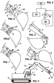
- a machine 1 includes a bucket 2 and at least one bucket actuator 3 which is operable by hydraulic pressure to tilt the bucket 2 in opposite, rack and dump directions between an upwardly facing, rack position ( Fig. 3 ) and a downwardly facing, dump position ( Fig. 4 ).
- the machine 1 may be configured as a steerable land vehicle which is mounted on wheels or tracks 4 and may be, for example, an excavator (as illustrated) or a backhoe loader.
- the machine may have a gross weight in excess of 1.5 tonnes, or 5 tonnes, or 10 tonnes, or 20 tonnes, up to as much as 100 tonnes or more.
- the bucket 2 may be mounted on the machine by means of a quick coupler 5 as well known in the art, comprising a mount 6 and a coupling mechanism 7 operated by at least one second actuator 8 to selectively lock the bucket to the mount.
- the mount 6 may be arranged at the distal end of a first arm or stick 9, which in turn is mounted at the distal end of a second arm or boom 10, with both arms 9, 10 being movable in rotation by hydraulic actuators 11.
- the bucket actuator 3 is a hydraulic ram mounted on the stick 9 to swivel the mount 6.
- the bucket may be used for digging or moving loose material in the vicinity of the machine, and may be interchangeable with other tools, for example, another bucket, a hydraulic breaker or a grab.
- the machine also includes at least one user control, which as illustrated may include a joystick 12.
- the at least one user control e.g. joystick 12
- the control signals include a bucket shake control signal 13'.
- the joystick 12 can be moved in opposite directions, as indicated by the arrows, to generate bucket rack and dump control signals, i.e. signals that command the bucket to move respectively to the rack and dump positions. Rapid and repeated movement of the joystick 12, by the operator, between its opposite positions on one axis of movement will thus produce the bucket shake control signal 13' as a series of alternate, repeated rack and dump signals.
- the user controls may include a dedicated bucket shake control (not shown), such as a button, which generates the bucket shake control signal 13' when activated by the user without requiring rapid and repeated user input.
- the machine also includes a hydraulic pump 14 for supplying hydraulic pressure to a supply line 15.
- a "line” means a fluid pathway that conveys hydraulic pressure, or a plurality of such fluid pathways that are interconnected to convey hydraulic pressure between multiple points, often referred to as a "network”.
- the hydraulic pump 14 may be a fixed displacement pump, for example, a gear pump.
- the pump 14 may be driven in rotation by an internal combustion engine 16 or other prime mover.
- the fixed displacement pump 14 may be coupled to the prime mover 16 in fixed ratio, which is to say, it may be driven by the prime mover at a speed that is fixed relative to the speed of the prime mover.
- the machine further includes a control system 20, which includes an unloader valve 21, a load sensing line 25, and a bucket control valve 26.
- the unloader valve 21 is openable in use, for example, by the hydraulic pressure produced by the pump 14 in the supply line 15, to relieve the hydraulic pressure from the supply line 15 to unload the hydraulic pump 14, and is closable by an unloader valve closing actuator 22.
- a bias spring 23 may act in the same (closing) direction as the closing actuator 22 in opposition to an opening actuator 24 which is energised by the pressure in the supply line 15, so that when the closing actuator 22 is not energised, the unloader valve 21 opens to relieve pressure from the supply line 15 when the pressure exceeds the bias force of the spring 23, which may be for example about 10 bar.
- the load sensing line 25 may form a network that is arranged to convey hydraulic pressure from multiple points in the system, indicative of a demand for hydraulic power from any element of the machine, for example, from hydraulic motors that drive the tracks 4 or from any of the hydraulic actuators 3, 8, 11.
- hydraulic pressure in the load sensing line is also referred to as a "pressure signal” or "LS signal”
- the load sensing line 25 is referred to for convenience as the "LS line” or "LS network”.
- the LS line 25 is arranged to apply a pressure signal, responsive to demand for hydraulic power, to the unloader valve closing actuator 22, to close the unloader valve 21 to maintain the hydraulic pressure in the supply line 15.
- the bucket control valve 26 may be a direction control spool valve, as illustrated, and is operable, in use, either directly or indirectly by the control signals 13, 13' to apply the hydraulic pressure from the supply line 15 to the at least one bucket actuator 3.
- the bucket control valve 26 is operable, responsive to the bucket shake control signal 13', to cause the at least one bucket actuator 3 to perform a bucket shake operation, which is a repeated movement of the bucket 2, alternately between the rack and dump positions, which is to say, alternately in the rack and dump directions towards the rack and dump positions, to shake debris from the bucket.
- a bucket shake operation which is a repeated movement of the bucket 2, alternately between the rack and dump positions, which is to say, alternately in the rack and dump directions towards the rack and dump positions, to shake debris from the bucket.
- the bucket may move from the rack position to the dump position and back again, or may move through a more limited range of movement in-between the rack and dump positions.
- the bucket or bucket actuator may engage a stop in either or both of the rack and dump positions to generate an impact which assists in detaching debris from the bucket, or the shaking action may be accomplished without hitting the stops.
- the bucket may move repeatedly from the dump position through a short distance towards the rack position and then back to the dump position.
- the control signals 13, 13' may be electrical signals, and the control system may include an electronic controller 17 which receives the electrical signals and, responsive thereto, controls the operation of pilot valves (not shown) which apply the hydraulic pilot pressure to the hydraulic actuators which operate a valve spool of the bucket control valve 26 and other control valves which, in turn, supply hydraulic pressure to the actuators, e.g. hydraulic cylinders 3, 11 that move the machine elements.
- the electrical signals 13, 13' may be applied directly to the solenoid or other actuators of the pilot valves.
- the electrical signals 13, 13', or electrical signals from the electronic controller 17 may be applied directly to solenoid or other electrical actuators that control movement of the valve spools of the valves that send pressure to the actuators that move the machine elements, as exemplified by the second actuator 8 which may be solenoid controlled as shown, although it could alternatively be controlled by pilot pressure.
- Fig. 2 can be implemented in various different ways. For clarity therefore, the control system depicted in Fig. 2 is simplified, and the electrical signal paths, pilot valves, pilot pressure supply lines and various other conventional details not essential to understanding of the present disclosure are not shown. Similarly, it will be understood that the opening and closing actuators and other functional elements of the valves are conventional, and may be implemented by appropriate configuration of a valve spool and housing or other subcomponents as well known in the art, for which reason they are not all illustrated in detail.
- the control system 20 is arranged to maintain a constant pressure signal in the load sensing line 25, to maintain the unloader valve 21 constantly in a closed condition, for the duration of the bucket shake operation (i.e. until the bucket shake operation ceases).
- a constant pressure signal is meant a signal that has a constant effect insofar as it maintains the unloader valve in a closed condition; which is to say, a signal that does not fluctuate, or that fluctuates in a manner or to a degree that does not cause the unloader valve 21 to open.
- the control system 20 may be arranged to maintain the constant pressure signal while the bucket shake control signal 13' persists, and to discontinue the constant pressure signal when the bucket shake control signal 13' ceases.
- the control system 20 may be arranged to maintain the constant pressure signal for a predefined time period (e.g. responsive to a timer) which is triggered by receiving the bucket shake control signal 13', and which also defines the duration of the bucket shake operation.
- the electronic controller 17 could include a program stored in non-transient memory which, when executed on a processor of the electronic controller, responsive to the bucket shake control signal 13', commands the bucket control valve 26 to perform the bucket shake operation, and also controls the operation of one or more hydraulic valves of the control system 20 to maintain the constant pressure signal for the duration of the bucket shake operation.
- the bucket shake control signal 13' may consist of a series of alternate control signals produced by repeated operation of the at least one user control, by the user - for example, by moving the joystick 12 rapidly and repeatedly between its opposite limit positions on the axis of movement that controls the tilt function of the bucket 2.
- the control system 20 may be arranged to maintain the constant pressure signal in the load sensing line responsive to repetition of such alternate control signals at a frequency above a threshold frequency.
- the threshold frequency could be defined by a certain number of transitions of the joystick 12 between the rack and dump position within a defined time period; for example, three transitions within a 500mS time period.
- control system 20 may be arranged to maintain the constant pressure signal while the bucket shake control signal 13' continues to satisfy the defined criterion over a rolling time period, and to discontinue the constant pressure signal when the criterion is no longer satisfied, which is to say, when the bucket shake control signal 13' ceases - for example, when the number of transitions falls below three over the immediately preceding 500mS time period.
- the electronic controller 17 may be arranged to monitor the electrical signals and to determine whether the electrical signals are repeated at a frequency above the threshold frequency.
- Fig. 8 illustrates an example control sequence to implement the method of the disclosure.
- the sequence begins at step S1 with the bucket shake control signal 13'.
- the method continues with operating the bucket control valve 26 (e.g. electrically and/or hydraulically by pilot pressure), responsive to the bucket shake control signal 13', to cause the at least one bucket actuator 3 to perform the bucket shake operation.
- the bucket control valve 26 e.g. electrically and/or hydraulically by pilot pressure
- the method includes, at step S4, maintaining a constant pressure signal in the load sensing line 25, to maintain the unloader valve 21 constantly in a closed condition, for a duration of the bucket shake operation.
- Step S4 may occur slightly before or after, or simultaneously with, step S2.
- the method may include, at step S3, determining (e.g. by electronic controller 17, if they are electrical signals), whether the alternate control signals are repeated at a frequency above the threshold frequency. If yes (Y), the method continues to step S4. If no (N), the sequence returns to S3, for example, by the electronic controller 17 continuing to monitor the control signals 13 to determine whether they are individual rack or dump signals or whether they are repeated rapidly enough to constitute a bucket shake control signal 13'.
- the control system 20 may be arranged to maintain the constant pressure signal in the LS line in any convenient way.
- One way to achieve this is by controlling the operation of a second actuator responsive to the bucket shake control signal 13', as will now be described.
- the machine 1 may further include at least one second actuator which is operable by the hydraulic pressure.
- the at least one second actuator 8 is arranged in the mount 6 to operate the coupling mechanism 7, although alternatively it could be any hydraulic actuator of the machine that can be constantly pressurised to a limit position during the bucket shake operation.
- the control system 20 includes a second actuator control valve 27 which is operable to apply the hydraulic pressure from the supply line 15 to the at least one second actuator 8.
- the LS line is arranged to apply the hydraulic pressure from the supply line, when applied to the at least one second actuator 8, as the pressure signal to the unloader valve closing actuator 22. As illustrated, this can be achieved by taking the LS pressure signal from a shuttle valve 28 arranged to communicate with the lines that supply pressure from the second actuator control valve 27 to the second actuator 8.
- the control system 20 may be arranged to operate the second actuator control valve 27 (e.g. by a signal from the electronic controller 17, responsive to identifying the bucket shake control signal 13'), to apply the hydraulic pressure from the supply line 15 constantly to the at least one second actuator 8 and, via the load sensing line 25, as the pressure signal to the unloader valve closing actuator 22, for the duration of the bucket shake operation.
- the second actuator control valve 27 e.g. by a signal from the electronic controller 17, responsive to identifying the bucket shake control signal 13'
- the at least one second actuator 8 may be operable to move the coupling mechanism 7 selectively between a locked position ( Fig. 7 ), in which the bucket 2 is locked to the mount 6 by the coupling mechanism 7, and a release position ( Fig. 6 ) in which the bucket 2 is unlocked from the mount 6, allowing it to be removed from mount as shown in Fig. 5 .
- the second actuator 8 is a hydraulic cylinder arranged in the mount 6, and the coupling mechanism 7 includes a wedge 29 which is urged by the second actuator 8 to engage in a recess 30 in the bucket 2 in the locked position.
- the coupling mechanism 7 includes a wedge 29 which is urged by the second actuator 8 to engage in a recess 30 in the bucket 2 in the locked position.
- Other arrangements are possible, as known in the art.
- the control system is arranged to operate the second actuator control valve 27, to apply the hydraulic pressure from the supply line 15 to the at least one second actuator 8, to urge the coupling mechanism 7 constantly towards the locked position for the duration of the bucket shake operation.
- the piston of the hydraulic cylinder is urged to its limit position, wherein the wedge 29 is engaged in the recess 30, and is maintained in this limit position for the duration of the bucket shake operation.
- the novel method may further include operating the second actuator control valve 27, to apply the hydraulic pressure from the supply line 15 constantly to the at least one second actuator 8 and, via the load sensing line 25, as the LS pressure signal to the unloader valve closing actuator 22, for the duration of the bucket shake operation.
- the method may further include operating the second actuator control valve 27, to apply the hydraulic pressure from the supply line 15 to the at least one second actuator 8, to urge the coupling mechanism 7 constantly towards the locked position for the duration of the bucket shake operation.
- Another shuttle valve 31 may be arranged to communicate with the lines that supply pressure from the bucket control valve 26 to the bucket actuator 3, which supplies a LS signal to the LS line 25 when the bucket is commanded to or towards the rack or dump position.
- This LS signal ensures that normal hydraulic pressure is maintained in the supply line 15 during the rack and dump operations, and will be applied also during the bucket shake operation.
- the constant LS signal applied in accordance with the disclosure, e.g. from shuttle valve 28, is found to be more reliable in maintaining the unloader valve 21 in the closed position during the bucket shake operation.
- the control system 20 may include a pressure relief valve 32 for the LS network and many other conventional elements which, although not all illustrated, will be evident to the skilled person.
- the novel control system can be applied to any work machine having a tilting bucket operated by a hydraulic pump with an unloader valve, but is particularly useful in machines having a fixed displacement pump, since the unloader valve makes it possible to drive the pump at a constant speed (hence, a constant output flow rate) that is governed by the speed of the prime mover and independent of the fluctuating demand for hydraulic power, resulting in a simple system.
- a constant speed high speed
- the unloader valve closes, the torque reaction of the pump increases, causing the prime mover to produce more power to maintain its governed speed.
- the unloader valve lags the signal, and main supply pressure lags the unloader valve.
- Hysteresis in the hydraulic control system thus results in an attenuated response at the unloader valve, and further attenuation of the fluctuating main supply pressure, in response to the rapidly fluctuating signal from the joystick or bucket shake control. Since the pump is unable to maintain normal operating pressure in the main supply line, the or each bucket actuator responds more slowly to the fluctuating bucket shake command than it would to a sustained, rack or dump command. In consequence, the machine operator may be frustrated by the less than vigorous response of the bucket.
- the operation of the pump maintains normal working pressure in the supply line while supplying the flow demanded by the bucket control valve to transition the bucket between the rack and dump directions.
- the more constant supply pressure allows the or each bucket actuator to move at normal operating speed, resulting in faster movement of the bucket between the rack and dump positions, which is to say, a more vigorous shaking action, so that debris is removed more effectively from the bucket.
- the constant pressure signal can be applied by applying hydraulic pressure to another (second) actuator of the machine to maintain it in its limit position for the duration of the bucket shake operation. Since the second actuator remains in its limit position, the constant pressure does not cause work to be done, but has the effect of raising LS pressure. In this way the constant pressure signal can be generated with few or no additional valve components, simplifying the system.
- the applied pressure can advantageously be used to urge the coupling mechanism constantly towards the locked position for the duration of the bucket shake operation. This can cause the coupling mechanism to hold the bucket more firmly to the mount during the bucket shake operation, which can help prevent damaging impact between the parts of the assembly.
- an excavator or other work machine includes a tilting bucket operated by a hydraulic actuator controlled by a bucket control valve responsive to control signals including a bucket shake control signal, which causes the bucket to move repeatedly in the rack and dump directions to shake debris from the bucket.
- the actuator is powered by pressure from a hydraulic pump, and a control system includes an unloader valve to relieve pressure from the supply line to unload the pump when there is no demand for power.
- the control system is arranged to maintain a constant pressure signal in a load sensing line, to maintain the unloader valve constantly in a closed condition, for the duration of the bucket shake operation. This may be achieved by pressurising an actuator of a quick coupler to lock the bucket to the machine.
Landscapes
- Engineering & Computer Science (AREA)
- Mining & Mineral Resources (AREA)
- Civil Engineering (AREA)
- General Engineering & Computer Science (AREA)
- Structural Engineering (AREA)
- Physics & Mathematics (AREA)
- Fluid Mechanics (AREA)
- Operation Control Of Excavators (AREA)
- Ship Loading And Unloading (AREA)
Applications Claiming Priority (2)
| Application Number | Priority Date | Filing Date | Title |
|---|---|---|---|
| GBGB2019672.1A GB202019672D0 (en) | 2020-12-14 | 2020-12-14 | Hydraulic control system and method for a bucket shake operation in a work machine with a hydraulic pump and unloader valve |
| GB2110140.7A GB2601859A (en) | 2020-12-14 | 2021-07-14 | Hydraulic control system and method for a bucket shake operation in a work machine with a hydraulic pump and unloader valve |
Publications (3)
| Publication Number | Publication Date |
|---|---|
| EP4012106A2 true EP4012106A2 (de) | 2022-06-15 |
| EP4012106A3 EP4012106A3 (de) | 2022-07-20 |
| EP4012106B1 EP4012106B1 (de) | 2023-07-26 |
Family
ID=78819735
Family Applications (1)
| Application Number | Title | Priority Date | Filing Date |
|---|---|---|---|
| EP21211339.3A Active EP4012106B1 (de) | 2020-12-14 | 2021-11-30 | Hydrauliksteuerungssystem und -verfahren für eine schaufelschütteloperation in einer arbeitsmaschine mit hydraulikpumpe und umlaufventil |
Country Status (4)
| Country | Link |
|---|---|
| US (1) | US11512449B2 (de) |
| EP (1) | EP4012106B1 (de) |
| CN (1) | CN114622619B (de) |
| GB (1) | GB202019672D0 (de) |
Families Citing this family (2)
| Publication number | Priority date | Publication date | Assignee | Title |
|---|---|---|---|---|
| CN117500986A (zh) | 2021-06-28 | 2024-02-02 | 斗山山猫北美公司 | 用于控制挖掘机和其他动力机器的系统和方法 |
| US20250198123A1 (en) * | 2023-12-14 | 2025-06-19 | Caterpillar Inc. | Implement metering control |
Family Cites Families (20)
| Publication number | Priority date | Publication date | Assignee | Title |
|---|---|---|---|---|
| US4731999A (en) | 1987-04-24 | 1988-03-22 | Vickers, Incorporated | Power transmission |
| US5235809A (en) * | 1991-09-09 | 1993-08-17 | Vickers, Incorporated | Hydraulic circuit for shaking a bucket on a vehicle |
| JP3151565B2 (ja) | 1991-10-18 | 2001-04-03 | トキコ株式会社 | サスペンション制御装置 |
| JPH10115365A (ja) | 1996-10-09 | 1998-05-06 | Zexel Corp | 無段変速機の油圧制御回路 |
| US6757992B1 (en) * | 2003-01-14 | 2004-07-06 | New Holland North America, Inc. | Skid steer loader bucket shaker |
| US7114747B2 (en) * | 2003-10-20 | 2006-10-03 | Cnh America Llc | Work vehicle stabilizer |
| US7036309B1 (en) | 2004-01-15 | 2006-05-02 | Sauer-Danfoss Inc. | Method of creating feedback control in a closed hydrostatic circuit and a control system therefore |
| SE526989C2 (sv) * | 2004-04-19 | 2005-11-29 | Volvo Constr Equip Holding Se | Metod för skakning av arbetsredskap |
| US7467514B2 (en) * | 2006-07-17 | 2008-12-23 | Caterpillar Inc. | System and method for controlling shakability of a work tool |
| US7726125B2 (en) * | 2007-07-31 | 2010-06-01 | Caterpillar Inc. | Hydraulic circuit for rapid bucket shake out |
| US7866149B2 (en) * | 2007-09-05 | 2011-01-11 | Caterpillar Inc | System and method for rapidly shaking an implement of a machine |
| WO2009067050A1 (en) * | 2007-11-21 | 2009-05-28 | Volvo Construction Equipment Ab | Load sensing system, working machine comprising the system, and method for controlling a hydraulic function |
| CN201443544U (zh) | 2009-04-16 | 2010-04-28 | 山推工程机械股份有限公司传动分公司 | 负载流量比例分配多路液压控制阀 |
| KR20110023285A (ko) | 2009-08-31 | 2011-03-08 | 현대모비스 주식회사 | 2단 오리피스타입 고압솔레노이드밸브 |
| EP2339073A1 (de) | 2009-12-23 | 2011-06-29 | Perkins Engines Company Limited | Hydrauliksystem für eine Maschine, Maschine und Anwendungsmethode |
| CN201787308U (zh) | 2010-08-30 | 2011-04-06 | 司红霞 | 卸荷阀及使用该卸荷阀的润滑系统 |
| CN104405005B (zh) * | 2014-11-27 | 2017-10-03 | 广西柳工机械股份有限公司 | 装载机铲装控制系统及铲装控制方法 |
| US10246855B2 (en) | 2016-10-10 | 2019-04-02 | Wacker Neuson Production Americas Llc | Material handling machine with bucket shake control system and method |
| US10597845B2 (en) | 2017-09-27 | 2020-03-24 | Deere & Company | Implement vibration system and method |
| CN111535393A (zh) * | 2020-05-25 | 2020-08-14 | 上海三一重机股份有限公司 | 挖掘机铲斗控制系统、方法及挖掘机 |
-
2020
- 2020-12-14 GB GBGB2019672.1A patent/GB202019672D0/en not_active Ceased
-
2021
- 2021-11-30 EP EP21211339.3A patent/EP4012106B1/de active Active
- 2021-12-07 CN CN202111483539.3A patent/CN114622619B/zh active Active
- 2021-12-14 US US17/550,894 patent/US11512449B2/en active Active
Also Published As
| Publication number | Publication date |
|---|---|
| US20220186471A1 (en) | 2022-06-16 |
| EP4012106A3 (de) | 2022-07-20 |
| CN114622619B (zh) | 2026-01-27 |
| GB202019672D0 (en) | 2021-01-27 |
| US11512449B2 (en) | 2022-11-29 |
| EP4012106B1 (de) | 2023-07-26 |
| CN114622619A (zh) | 2022-06-14 |
Similar Documents
| Publication | Publication Date | Title |
|---|---|---|
| EP0614016B1 (de) | Hydraulische antriebsvorrichtung einer hydraulischen baumaschine | |
| CN101978174B (zh) | 液压油供给装置及建筑机械 | |
| EP0206934B1 (de) | Vorrichtung zur wahlweisen Steuerung von mehreren Arten hydraulischer Antriebsvorrichtungen | |
| GB2601859A (en) | Hydraulic control system and method for a bucket shake operation in a work machine with a hydraulic pump and unloader valve | |
| EP1178158A1 (de) | Arbeitsmaschine mit feinregelbaren Betriebsarten | |
| EP4012106B1 (de) | Hydrauliksteuerungssystem und -verfahren für eine schaufelschütteloperation in einer arbeitsmaschine mit hydraulikpumpe und umlaufventil | |
| WO2008133835A1 (en) | Anti-stall system utilizing implement pilot relief | |
| US7048515B2 (en) | Hydraulic drive system and method using a fuel injection control unit | |
| JP6683641B2 (ja) | 油圧ショベル | |
| EP1398512B1 (de) | Hydraulische antriebseinheit einer arbeitsmaschine, und hydaulisches antriebsverfahren | |
| JP7472321B2 (ja) | 作業機械 | |
| JPH08219107A (ja) | 油圧機械の油圧再生装置 | |
| CN114423907A (zh) | 工程机械 | |
| JP3445817B2 (ja) | 建設機械の油圧駆動装置 | |
| JP2786941B2 (ja) | 作業機械の油圧駆動装置 | |
| KR102487257B1 (ko) | 건설 기계 | |
| WO1990010795A1 (fr) | Unite de commande hydraulique pour engin de terrassement | |
| CN116964337B (zh) | 工程机械 | |
| CN116057283A (zh) | 作业机械 | |
| JP2000310202A (ja) | 建設機械の油圧駆動装置 | |
| US20260125877A1 (en) | Working machine | |
| JPWO1990010795A1 (ja) | 作業機械の油圧駆動装置 | |
| JP3339821B2 (ja) | 作業機械のロック方法およびそのロック装置 | |
| EP4382675A1 (de) | Baumaschine | |
| JP7436301B2 (ja) | 建設機械 |
Legal Events
| Date | Code | Title | Description |
|---|---|---|---|
| PUAI | Public reference made under article 153(3) epc to a published international application that has entered the european phase |
Free format text: ORIGINAL CODE: 0009012 |
|
| STAA | Information on the status of an ep patent application or granted ep patent |
Free format text: STATUS: THE APPLICATION HAS BEEN PUBLISHED |
|
| AK | Designated contracting states |
Kind code of ref document: A2 Designated state(s): AL AT BE BG CH CY CZ DE DK EE ES FI FR GB GR HR HU IE IS IT LI LT LU LV MC MK MT NL NO PL PT RO RS SE SI SK SM TR |
|
| PUAL | Search report despatched |
Free format text: ORIGINAL CODE: 0009013 |
|
| AK | Designated contracting states |
Kind code of ref document: A3 Designated state(s): AL AT BE BG CH CY CZ DE DK EE ES FI FR GB GR HR HU IE IS IT LI LT LU LV MC MK MT NL NO PL PT RO RS SE SI SK SM TR |
|
| RIC1 | Information provided on ipc code assigned before grant |
Ipc: E02F 9/22 20060101ALI20220614BHEP Ipc: E02F 3/40 20060101AFI20220614BHEP |
|
| STAA | Information on the status of an ep patent application or granted ep patent |
Free format text: STATUS: REQUEST FOR EXAMINATION WAS MADE |
|
| 17P | Request for examination filed |
Effective date: 20221219 |
|
| RBV | Designated contracting states (corrected) |
Designated state(s): AL AT BE BG CH CY CZ DE DK EE ES FI FR GB GR HR HU IE IS IT LI LT LU LV MC MK MT NL NO PL PT RO RS SE SI SK SM TR |
|
| GRAP | Despatch of communication of intention to grant a patent |
Free format text: ORIGINAL CODE: EPIDOSNIGR1 |
|
| STAA | Information on the status of an ep patent application or granted ep patent |
Free format text: STATUS: GRANT OF PATENT IS INTENDED |
|
| INTG | Intention to grant announced |
Effective date: 20230220 |
|
| GRAS | Grant fee paid |
Free format text: ORIGINAL CODE: EPIDOSNIGR3 |
|
| GRAA | (expected) grant |
Free format text: ORIGINAL CODE: 0009210 |
|
| STAA | Information on the status of an ep patent application or granted ep patent |
Free format text: STATUS: THE PATENT HAS BEEN GRANTED |
|
| P01 | Opt-out of the competence of the unified patent court (upc) registered |
Effective date: 20230526 |
|
| AK | Designated contracting states |
Kind code of ref document: B1 Designated state(s): AL AT BE BG CH CY CZ DE DK EE ES FI FR GB GR HR HU IE IS IT LI LT LU LV MC MK MT NL NO PL PT RO RS SE SI SK SM TR |
|
| REG | Reference to a national code |
Ref country code: CH Ref legal event code: EP |
|
| REG | Reference to a national code |
Ref country code: IE Ref legal event code: FG4D |
|
| REG | Reference to a national code |
Ref country code: DE Ref legal event code: R096 Ref document number: 602021003800 Country of ref document: DE |
|
| REG | Reference to a national code |
Ref country code: SE Ref legal event code: TRGR |
|
| REG | Reference to a national code |
Ref country code: LT Ref legal event code: MG9D |
|
| REG | Reference to a national code |
Ref country code: NL Ref legal event code: MP Effective date: 20230726 |
|
| REG | Reference to a national code |
Ref country code: AT Ref legal event code: MK05 Ref document number: 1592042 Country of ref document: AT Kind code of ref document: T Effective date: 20230726 |
|
| PG25 | Lapsed in a contracting state [announced via postgrant information from national office to epo] |
Ref country code: NL Free format text: LAPSE BECAUSE OF FAILURE TO SUBMIT A TRANSLATION OF THE DESCRIPTION OR TO PAY THE FEE WITHIN THE PRESCRIBED TIME-LIMIT Effective date: 20230726 |
|
| PG25 | Lapsed in a contracting state [announced via postgrant information from national office to epo] |
Ref country code: GR Free format text: LAPSE BECAUSE OF FAILURE TO SUBMIT A TRANSLATION OF THE DESCRIPTION OR TO PAY THE FEE WITHIN THE PRESCRIBED TIME-LIMIT Effective date: 20231027 |
|
| PG25 | Lapsed in a contracting state [announced via postgrant information from national office to epo] |
Ref country code: IS Free format text: LAPSE BECAUSE OF FAILURE TO SUBMIT A TRANSLATION OF THE DESCRIPTION OR TO PAY THE FEE WITHIN THE PRESCRIBED TIME-LIMIT Effective date: 20231126 |
|
| PG25 | Lapsed in a contracting state [announced via postgrant information from national office to epo] |
Ref country code: RS Free format text: LAPSE BECAUSE OF FAILURE TO SUBMIT A TRANSLATION OF THE DESCRIPTION OR TO PAY THE FEE WITHIN THE PRESCRIBED TIME-LIMIT Effective date: 20230726 Ref country code: PT Free format text: LAPSE BECAUSE OF FAILURE TO SUBMIT A TRANSLATION OF THE DESCRIPTION OR TO PAY THE FEE WITHIN THE PRESCRIBED TIME-LIMIT Effective date: 20231127 Ref country code: NO Free format text: LAPSE BECAUSE OF FAILURE TO SUBMIT A TRANSLATION OF THE DESCRIPTION OR TO PAY THE FEE WITHIN THE PRESCRIBED TIME-LIMIT Effective date: 20231026 Ref country code: LV Free format text: LAPSE BECAUSE OF FAILURE TO SUBMIT A TRANSLATION OF THE DESCRIPTION OR TO PAY THE FEE WITHIN THE PRESCRIBED TIME-LIMIT Effective date: 20230726 Ref country code: LT Free format text: LAPSE BECAUSE OF FAILURE TO SUBMIT A TRANSLATION OF THE DESCRIPTION OR TO PAY THE FEE WITHIN THE PRESCRIBED TIME-LIMIT Effective date: 20230726 Ref country code: IS Free format text: LAPSE BECAUSE OF FAILURE TO SUBMIT A TRANSLATION OF THE DESCRIPTION OR TO PAY THE FEE WITHIN THE PRESCRIBED TIME-LIMIT Effective date: 20231126 Ref country code: HR Free format text: LAPSE BECAUSE OF FAILURE TO SUBMIT A TRANSLATION OF THE DESCRIPTION OR TO PAY THE FEE WITHIN THE PRESCRIBED TIME-LIMIT Effective date: 20230726 Ref country code: GR Free format text: LAPSE BECAUSE OF FAILURE TO SUBMIT A TRANSLATION OF THE DESCRIPTION OR TO PAY THE FEE WITHIN THE PRESCRIBED TIME-LIMIT Effective date: 20231027 Ref country code: FI Free format text: LAPSE BECAUSE OF FAILURE TO SUBMIT A TRANSLATION OF THE DESCRIPTION OR TO PAY THE FEE WITHIN THE PRESCRIBED TIME-LIMIT Effective date: 20230726 Ref country code: AT Free format text: LAPSE BECAUSE OF FAILURE TO SUBMIT A TRANSLATION OF THE DESCRIPTION OR TO PAY THE FEE WITHIN THE PRESCRIBED TIME-LIMIT Effective date: 20230726 |
|
| PG25 | Lapsed in a contracting state [announced via postgrant information from national office to epo] |
Ref country code: PL Free format text: LAPSE BECAUSE OF FAILURE TO SUBMIT A TRANSLATION OF THE DESCRIPTION OR TO PAY THE FEE WITHIN THE PRESCRIBED TIME-LIMIT Effective date: 20230726 |
|
| PG25 | Lapsed in a contracting state [announced via postgrant information from national office to epo] |
Ref country code: ES Free format text: LAPSE BECAUSE OF FAILURE TO SUBMIT A TRANSLATION OF THE DESCRIPTION OR TO PAY THE FEE WITHIN THE PRESCRIBED TIME-LIMIT Effective date: 20230726 |
|
| REG | Reference to a national code |
Ref country code: DE Ref legal event code: R097 Ref document number: 602021003800 Country of ref document: DE |
|
| PG25 | Lapsed in a contracting state [announced via postgrant information from national office to epo] |
Ref country code: SM Free format text: LAPSE BECAUSE OF FAILURE TO SUBMIT A TRANSLATION OF THE DESCRIPTION OR TO PAY THE FEE WITHIN THE PRESCRIBED TIME-LIMIT Effective date: 20230726 Ref country code: RO Free format text: LAPSE BECAUSE OF FAILURE TO SUBMIT A TRANSLATION OF THE DESCRIPTION OR TO PAY THE FEE WITHIN THE PRESCRIBED TIME-LIMIT Effective date: 20230726 Ref country code: ES Free format text: LAPSE BECAUSE OF FAILURE TO SUBMIT A TRANSLATION OF THE DESCRIPTION OR TO PAY THE FEE WITHIN THE PRESCRIBED TIME-LIMIT Effective date: 20230726 Ref country code: EE Free format text: LAPSE BECAUSE OF FAILURE TO SUBMIT A TRANSLATION OF THE DESCRIPTION OR TO PAY THE FEE WITHIN THE PRESCRIBED TIME-LIMIT Effective date: 20230726 Ref country code: DK Free format text: LAPSE BECAUSE OF FAILURE TO SUBMIT A TRANSLATION OF THE DESCRIPTION OR TO PAY THE FEE WITHIN THE PRESCRIBED TIME-LIMIT Effective date: 20230726 Ref country code: CZ Free format text: LAPSE BECAUSE OF FAILURE TO SUBMIT A TRANSLATION OF THE DESCRIPTION OR TO PAY THE FEE WITHIN THE PRESCRIBED TIME-LIMIT Effective date: 20230726 Ref country code: SK Free format text: LAPSE BECAUSE OF FAILURE TO SUBMIT A TRANSLATION OF THE DESCRIPTION OR TO PAY THE FEE WITHIN THE PRESCRIBED TIME-LIMIT Effective date: 20230726 |
|
| PLBE | No opposition filed within time limit |
Free format text: ORIGINAL CODE: 0009261 |
|
| STAA | Information on the status of an ep patent application or granted ep patent |
Free format text: STATUS: NO OPPOSITION FILED WITHIN TIME LIMIT |
|
| PG25 | Lapsed in a contracting state [announced via postgrant information from national office to epo] |
Ref country code: MC Free format text: LAPSE BECAUSE OF FAILURE TO SUBMIT A TRANSLATION OF THE DESCRIPTION OR TO PAY THE FEE WITHIN THE PRESCRIBED TIME-LIMIT Effective date: 20230726 |
|
| 26N | No opposition filed |
Effective date: 20240429 |
|
| PG25 | Lapsed in a contracting state [announced via postgrant information from national office to epo] |
Ref country code: LU Free format text: LAPSE BECAUSE OF NON-PAYMENT OF DUE FEES Effective date: 20231130 |
|
| PG25 | Lapsed in a contracting state [announced via postgrant information from national office to epo] |
Ref country code: MC Free format text: LAPSE BECAUSE OF FAILURE TO SUBMIT A TRANSLATION OF THE DESCRIPTION OR TO PAY THE FEE WITHIN THE PRESCRIBED TIME-LIMIT Effective date: 20230726 Ref country code: LU Free format text: LAPSE BECAUSE OF NON-PAYMENT OF DUE FEES Effective date: 20231130 Ref country code: SI Free format text: LAPSE BECAUSE OF FAILURE TO SUBMIT A TRANSLATION OF THE DESCRIPTION OR TO PAY THE FEE WITHIN THE PRESCRIBED TIME-LIMIT Effective date: 20230726 |
|
| REG | Reference to a national code |
Ref country code: BE Ref legal event code: MM Effective date: 20231130 |
|
| REG | Reference to a national code |
Ref country code: IE Ref legal event code: MM4A |
|
| PG25 | Lapsed in a contracting state [announced via postgrant information from national office to epo] |
Ref country code: IE Free format text: LAPSE BECAUSE OF NON-PAYMENT OF DUE FEES Effective date: 20231130 |
|
| PG25 | Lapsed in a contracting state [announced via postgrant information from national office to epo] |
Ref country code: BE Free format text: LAPSE BECAUSE OF NON-PAYMENT OF DUE FEES Effective date: 20231130 |
|
| PG25 | Lapsed in a contracting state [announced via postgrant information from national office to epo] |
Ref country code: FR Free format text: LAPSE BECAUSE OF NON-PAYMENT OF DUE FEES Effective date: 20231130 |
|
| PG25 | Lapsed in a contracting state [announced via postgrant information from national office to epo] |
Ref country code: IE Free format text: LAPSE BECAUSE OF NON-PAYMENT OF DUE FEES Effective date: 20231130 Ref country code: FR Free format text: LAPSE BECAUSE OF NON-PAYMENT OF DUE FEES Effective date: 20231130 Ref country code: BE Free format text: LAPSE BECAUSE OF NON-PAYMENT OF DUE FEES Effective date: 20231130 |
|
| PG25 | Lapsed in a contracting state [announced via postgrant information from national office to epo] |
Ref country code: BG Free format text: LAPSE BECAUSE OF FAILURE TO SUBMIT A TRANSLATION OF THE DESCRIPTION OR TO PAY THE FEE WITHIN THE PRESCRIBED TIME-LIMIT Effective date: 20230726 |
|
| PG25 | Lapsed in a contracting state [announced via postgrant information from national office to epo] |
Ref country code: BG Free format text: LAPSE BECAUSE OF FAILURE TO SUBMIT A TRANSLATION OF THE DESCRIPTION OR TO PAY THE FEE WITHIN THE PRESCRIBED TIME-LIMIT Effective date: 20230726 |
|
| REG | Reference to a national code |
Ref country code: CH Ref legal event code: PL |
|
| REG | Reference to a national code |
Ref country code: CH Ref legal event code: PL |
|
| PG25 | Lapsed in a contracting state [announced via postgrant information from national office to epo] |
Ref country code: CH Free format text: LAPSE BECAUSE OF NON-PAYMENT OF DUE FEES Effective date: 20241130 |
|
| PG25 | Lapsed in a contracting state [announced via postgrant information from national office to epo] |
Ref country code: CY Free format text: LAPSE BECAUSE OF FAILURE TO SUBMIT A TRANSLATION OF THE DESCRIPTION OR TO PAY THE FEE WITHIN THE PRESCRIBED TIME-LIMIT; INVALID AB INITIO Effective date: 20211130 |
|
| PG25 | Lapsed in a contracting state [announced via postgrant information from national office to epo] |
Ref country code: TR Free format text: LAPSE BECAUSE OF FAILURE TO SUBMIT A TRANSLATION OF THE DESCRIPTION OR TO PAY THE FEE WITHIN THE PRESCRIBED TIME-LIMIT Effective date: 20230726 |
|
| PGFP | Annual fee paid to national office [announced via postgrant information from national office to epo] |
Ref country code: DE Payment date: 20251022 Year of fee payment: 5 |
|
| PGFP | Annual fee paid to national office [announced via postgrant information from national office to epo] |
Ref country code: GB Payment date: 20251023 Year of fee payment: 5 |
|
| PGFP | Annual fee paid to national office [announced via postgrant information from national office to epo] |
Ref country code: IT Payment date: 20251022 Year of fee payment: 5 |
|
| PGFP | Annual fee paid to national office [announced via postgrant information from national office to epo] |
Ref country code: SE Payment date: 20251022 Year of fee payment: 5 |