EP4011784A1 - Verfahren und vorrichtungen zur entkopplung eines rumpfes von einem dorn - Google Patents
Verfahren und vorrichtungen zur entkopplung eines rumpfes von einem dorn Download PDFInfo
- Publication number
- EP4011784A1 EP4011784A1 EP21211938.2A EP21211938A EP4011784A1 EP 4011784 A1 EP4011784 A1 EP 4011784A1 EP 21211938 A EP21211938 A EP 21211938A EP 4011784 A1 EP4011784 A1 EP 4011784A1
- Authority
- EP
- European Patent Office
- Prior art keywords
- tubular structure
- strongback
- actuators
- elongated members
- fuselage
- Prior art date
- Legal status (The legal status is an assumption and is not a legal conclusion. Google has not performed a legal analysis and makes no representation as to the accuracy of the status listed.)
- Granted
Links
Images









Classifications
-
- B—PERFORMING OPERATIONS; TRANSPORTING
- B25—HAND TOOLS; PORTABLE POWER-DRIVEN TOOLS; MANIPULATORS
- B25J—MANIPULATORS; CHAMBERS PROVIDED WITH MANIPULATION DEVICES
- B25J15/00—Gripping heads and other end effectors
- B25J15/06—Gripping heads and other end effectors with vacuum or magnetic holding means
- B25J15/0616—Gripping heads and other end effectors with vacuum or magnetic holding means with vacuum
-
- B—PERFORMING OPERATIONS; TRANSPORTING
- B23—MACHINE TOOLS; METAL-WORKING NOT OTHERWISE PROVIDED FOR
- B23Q—DETAILS, COMPONENTS, OR ACCESSORIES FOR MACHINE TOOLS, e.g. ARRANGEMENTS FOR COPYING OR CONTROLLING; MACHINE TOOLS IN GENERAL CHARACTERISED BY THE CONSTRUCTION OF PARTICULAR DETAILS OR COMPONENTS; COMBINATIONS OR ASSOCIATIONS OF METAL-WORKING MACHINES, NOT DIRECTED TO A PARTICULAR RESULT
- B23Q3/00—Devices holding, supporting, or positioning work or tools, of a kind normally removable from the machine
- B23Q3/12—Devices holding, supporting, or positioning work or tools, of a kind normally removable from the machine for securing to a spindle in general
-
- B—PERFORMING OPERATIONS; TRANSPORTING
- B25—HAND TOOLS; PORTABLE POWER-DRIVEN TOOLS; MANIPULATORS
- B25J—MANIPULATORS; CHAMBERS PROVIDED WITH MANIPULATION DEVICES
- B25J15/00—Gripping heads and other end effectors
- B25J15/0052—Gripping heads and other end effectors multiple gripper units or multiple end effectors
-
- B—PERFORMING OPERATIONS; TRANSPORTING
- B64—AIRCRAFT; AVIATION; COSMONAUTICS
- B64F—GROUND OR AIRCRAFT-CARRIER-DECK INSTALLATIONS SPECIALLY ADAPTED FOR USE IN CONNECTION WITH AIRCRAFT; DESIGNING, MANUFACTURING, ASSEMBLING, CLEANING, MAINTAINING OR REPAIRING AIRCRAFT, NOT OTHERWISE PROVIDED FOR; HANDLING, TRANSPORTING, TESTING OR INSPECTING AIRCRAFT COMPONENTS, NOT OTHERWISE PROVIDED FOR
- B64F5/00—Designing, manufacturing, assembling, cleaning, maintaining or repairing aircraft, not otherwise provided for; Handling, transporting, testing or inspecting aircraft components, not otherwise provided for
- B64F5/10—Manufacturing or assembling aircraft, e.g. jigs therefor
-
- B—PERFORMING OPERATIONS; TRANSPORTING
- B64—AIRCRAFT; AVIATION; COSMONAUTICS
- B64C—AEROPLANES; HELICOPTERS
- B64C1/00—Fuselages; Constructional features common to fuselages, wings, stabilising surfaces or the like
- B64C1/06—Frames; Stringers; Longerons ; Fuselage sections
- B64C1/068—Fuselage sections
Definitions
- the present disclosure relates generally to strongback apparatuses, and more particularly, to strongback apparatuses and methods for using strongback apparatuses to decouple a fuselage from a mandrel.
- a method comprises positioning a strongback apparatus on a first tubular structure, where the first tubular structure is coupled to a second tubular structure.
- the strongback apparatus comprises an arcuate central body comprising a front end, a rear end, and a plurality of elongated members that connect the front end to the rear end, and a plurality of actuators pivotably mounted to the plurality of elongated members, where the plurality of actuators are configured to move in a radially outward direction and comprise (i) proximal ends pivotably mounted to the plurality of elongated members and (ii) distal ends having vacuum suction cups.
- the method also comprises operating a vacuum source to engage the vacuum suction cups of the plurality of actuators with the first tubular structure.
- the method also comprises while the vacuum suction cups of the plurality of actuators are engaged with the first tubular structure, controlling the plurality of actuators to pull the first tubular structure away from the second tubular structure in the radially outward direction.
- the method also comprises while pulling the first tubular structure away from the second tubular structure in the radially outward direction, decoupling, with the strongback apparatus, the first tubular structure from the second tubular structure.
- a strongback apparatus comprises an arcuate central body comprising a front end, a rear end, and a plurality of elongated members that connect the front end to the rear end.
- the strongback apparatus also comprises a plurality of actuators pivotably mounted to the plurality of elongated members.
- the plurality of actuators are configured to move in a radially outward direction and comprise (i) proximal ends pivotably mounted to the plurality of elongated members and (ii) distal ends having vacuum suction cups.
- a system comprising a one-piece mandrel, a fuselage coupled to the one-piece mandrel, and a strongback apparatus positioned on the fuselage.
- the strongback apparatus comprises an arcuate central body comprising a front end, a rear end, and a plurality of elongated members that connect the front end to the rear end, and actuators mounted to the plurality of elongated members.
- the actuators are configured to move in a radially outward direction from extended positions to retracted positions and comprise (i) proximal ends mounted to the plurality of elongated members and (ii) distal ends having vacuum suction cups. In the extended positions, the vacuum suction cups engage the fuselage on which the strongback apparatus is positioned. As the actuators moves from the extended positions to the retracted positions, the vacuum suction cups pull the fuselage away from the one-piece mandrel.
- an improved strongback apparatus that can be used for decoupling a first tubular structure from a second tubular structure.
- first tubular structure and second tubular structure taking the forms of a fuselage and mandrel, respectively, it should be understood that the disclosed strongback apparatus can be used for processes in which the first tubular structure and second tubular structure take the forms of a caul plate (or plates) and a fuselage, respectively.
- the disclosed strongback apparatus includes, in part, actuators (e.g., pneumatic actuators) that engage, via a vacuum, to the fuselage and spread the fuselage (e.g., sections of a bisected fuselage) apart from the mandrel, so that the fuselage can be more easily lifted off the fuselage.
- actuators e.g., pneumatic actuators
- the disclosed strongback apparatus also includes spreader arms that are removably attached to the strongback apparatus and used, along with corresponding winch straps, to further secure the fuselage and to spread the fuselage farther, thus providing additional help when decoupling the fuselage from the mandrel.
- the disclosed strongback apparatus also advantageously allows for a one-piece mandrel to be used during processes for removing caul plates, trimming/bisecting a fuselage, and decoupling the fuselage from the one-piece mandrel.
- a one-piece mandrel is not segmented or fabricated in the same manner as existing mandrels. Rather, using the strongback apparatuses described herein, the fuselage is bisected and removed from the one-piece mandrel and the one-piece mandrel is left intact, thus decreasing complexity and allowing for the process to be completed more efficiently.
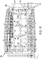
- Figure 1 depicts a perspective view of an example of a strongback apparatus 100.
- the strongback apparatus 100 includes an arcuate central body 102 and a plurality of actuators 104.
- the arcuate central body 102 has a front end 106, a rear end 108, and a plurality of elongated members 110 that connect the front end 106 to the rear end 108.
- Arrows labeled "Front” and “Rear” are shown, and correspond to the orientation of front and rear ends of a fuselage (not shown) and mandrel (not shown) with which the strongback apparatus 100 interacts.
- the arcuate central body 102 and the plurality of elongated members 110 are made of metal, although other materials are possible as well.
- the plurality of actuators 104 are configured to move from an extended position to a retracted position in a radially outward direction, and from the retracted position back to the extended position.
- the plurality of actuators 104 are pneumatic, linear actuators.
- the plurality of actuators 104 include at least one other type of actuator, such as an electromechanical actuator.
- the plurality of elongated members 110 includes a pair of peripheral elongated members 112 that define longitudinal edges of the arcuate central body 102, and the plurality of actuators 104 are pivotably mounted to the pair of peripheral elongated members 112.
- the strongback apparatus 100 includes a plurality of vacuum cups 114 fixedly mounted to the plurality of elongated members 110.
- the plurality of vacuum cups 114 are fixedly mounted to all of the elongated members to the plurality of elongated members 110 except the pair of peripheral elongated members 112.
- each of the plurality of vacuum cups 114 can be fixedly mounted to a respective bracket, which is in turn fixedly mounted to one of the plurality of elongated members 110 other than the pair of peripheral elongated members 112.
- the reference number for the plurality of vacuum cups 114 designates three representative examples of such vacuum cups, although others are shown as well, particularly along some of the elongated members of the plurality of elongated members 110 other than the pair of peripheral elongated members 112.
- the plurality of vacuum cups 114 can include thirty-six vacuum cups, although more or less are possible.
- the plurality of vacuum cups 114 can help grip and remove caul plates (not shown) from a fuselage and can help bisect and demold a fuselage from a mandrel.
- the strongback apparatus 100 can include a plurality of ports 116 (e.g., four ports, with one on each corner of the strongback apparatus 100) and tubes (not shown) that couple the plurality of actuators 104 and the plurality of vacuum cups 114 to a vacuum source (not shown in Figure 1 , but shown in later figures) configured to promote vacuum suction between the plurality of actuators 104 and the plurality of vacuum cups 114 and a surface, such as a surface of a fuselage or a caul plate.
- a vacuum source not shown in Figure 1 , but shown in later figures
- the plurality of ports 116 can all be plumed as a closed system to provide vacuum to the plurality of actuators 104 and the plurality of vacuum cups 114 via the tubes.
- each port can be part of a utility manifold that includes one air fitting, one vacuum fitting, one vacuum gauge, and a vacuum vent valve. To release a caul plate or the fuselage, the vacuum vent valve can be opened, thus disengaging the vacuum.
- the plurality of actuators 104 are pivotably mounted to the plurality of elongated members 110.
- the strongback apparatus 100 includes a plurality of brackets fastened to the plurality of elongated members 110 (e.g., the pair of peripheral elongated members 112), and the plurality of actuators 104 are pivotably mounted to the plurality of brackets.
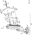
- Figure 2 depicts a perspective view of an actuator 120 of the plurality of actuators 104, which is pivotably mounted to a bracket 122.
- Actuator 120 (and all components thereof shown in Figure 2 and Figure 3 ) is treated herein as a representative example of the plurality of actuators 104.
- Bracket 122 is treated as a representative example of the plurality of brackets that are fastened to the plurality of elongated members 110.
- Figure 2 shows bracket 122 fastened to (e.g., via one or more screws, bolts, or other fasteners) one of the pair of peripheral elongated members 112.
- actuator 120 includes a proximal end 124 pivotably mounted to bracket 122, and thus pivotably mounted to the one of the pair of peripheral elongated members 112 by way of bracket 122.
- Actuator 120 also includes a distal end 126 having a vacuum suction cup 128.
- the vacuum suction cup 128 is configured to be coupled to a vacuum source (not shown).
- Figure 3 depicts an exploded view of an example assembly for pivotably mounting actuator 120 to bracket 122.
- actuator 120 is attached to an actuator plate 130, which is in turn pivotaby mounted to bracket 122 by disposing a shoulder screw 132 through a hole in a thrust washer 134 positioned between the actuator plate 130 and then through a hole in bracket 122.
- a thrust bearing 136, two Belleville washers 138, a plain washer 140, and a lock nut 142 are then attached to the end of the shoulder screw 132.
- other components can be used to mount actuator 120, such as a pivot pin instead of the shoulder screw.
- the proximal end 124 of actuator 120 includes detent pins 144.
- the detent pins 144 are coupled to the actuator plate 130 via jam nuts 146 and protrude through opposing ears that protrude from sides of the actuator plate 130.
- Bracket 122 thus includes detent holes 148 configured for receiving the detent pins 144.
- more or less detent pins and/or detent holes are possible than those shown in Figure 3 .
- the plurality of actuators 104 can be configured to spread open a caul plate for installation or removal from a fuselage, or to spread open a fuselage for removal from a mandrel. To facilitate this, each of the plurality of actuators 104 is configured to move from an extended position to a retracted position in a radially outward direction to spread the caul plate or fuselage, and then can be kept back in the extended position when not in use.
- the detent pins 144 and the detent holes 148 are used to set actuator 120 orientation at a "home" position before actuator 120 interfaces with a caul plate or fuselage. To do this, the angle of the actuator 120 can be adjusted until the detent pins 144 (i.e., both detent pins) are locked into the detent holes 148.
- actuator 120 can then rotate/swivel about the shoulder screw 132 as actuator 120 moves to the retracted position, thereby spreading the fuselage and pulling the fuselage away from the mandrel (or thereby spreading the caul plate and pulling the caul plate away from the fuselage).
- This rotation/swivel can be helpful for keeping the vacuum suction cup 128 in intimate contact with the caul plate or fuselage during the movement in the radially outward direction from the extended position to the retracted position. Otherwise, shear force between the vacuum suction cup 128 and the surface of the caul plate or fuselage can overcome the vacuum force and detach the caul plate or fuselage, due to the spreading of the caul plate or fuselage open in an arc-like shape.
- the strongback apparatus 100 can include additional components to further assist with the processes described herein.
- Figure 4 depicts a perspective view of a plurality of spreader arms 150 that are removably attached to the pair of peripheral elongated members 112.
- the plurality of spreader arms 150 are removable so that they are not in the way when trimming/bisecting a caul plate or fuselage and can be attached after such processes are complete.
- the plurality of spreader arms 150 also includes spreader arms removably attached to the other of the pair of peripheral elongated members 112.
- the strongback apparatus 100 also includes a plurality of winch straps 152, each corresponding to a respective one of the plurality of spreader arms 150. As shown, the plurality of spreader arms 150 are each bent, so as to substantially mimic an arcuate shape of a fuselage. Within examples, the strongback apparatus 100 includes eight spreader arms, four of which are shown in Figure 4 .
- Figure 4 designates spreader arm 154 as representative example of the plurality of spreader arms 150.
- Spreader arm 154 includes a proximal end 156 and a distal end 158.
- the proximal end 156 is removably attached to the pair of peripheral elongated members 112.
- the distal end 158 includes a winch 160 that is rigidly attached to the remainder of spreader arm 154.
- the winch 160 can be a manual winch, such as a worm drive hand winch, or can be another type of manual or electrically-operated winch.
- FIG. 4 also designates winch strap 162 as representative example of the plurality of winch straps 152, which corresponds to spreader arm 154.
- Winch strap 162 includes a first end 164 that is attachable to the winch 160 of spreader arm 154, and also includes a second end 166 having a clip 168.
- the pair of peripheral elongated members 112 include a plurality of receiver slots 169 configured for receiving the plurality of spreader arms 150.
- proximal ends of the plurality of spreader arms 150 e.g., proximal end 156
- quick-release pins, bolts, or other fasteners can be inserted through holes in both the plurality of receiver slots 169 and the proximal ends of the plurality of spreader arms 150.
- Figure 5 depicts a perspective view of an example of how the clip 168 can be attached to a fuselage 170.
- the fuselage 170 has a tooling tab 172.
- the tooling tab 172 can be disposed through a hole in the clip 168.
- a quick-release pin 174 can then be inserted through a hole in the tooling tab 172 to secure the clip 168.
- the clip 168 is shaped to contact an underside and side of the fuselage 170 during operation (e.g., during the spreading and lifting of the fuselage 170).
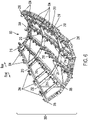
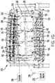
- Figure 6 depicts a perspective view of an example of a second strongback apparatus 200.
- the second strongback apparatus 200 includes a second arcuate central body 202 and a second plurality of actuators 204.
- the second arcuate central body 202 has a second front end 206, a second rear end 208, and a second plurality of elongated members 210 that connect the second front end 206 to the second rear end 208.
- the second plurality of actuators 204 are configured to move from an extended position to a retracted position in a radially outward direction, and from the retracted position back to the extended position.
- the second plurality of actuators 204 include second proximal ends pivotably mounted to the second plurality of elongated members 210, and also include second distal ends having second vacuum suction cups.
- each of the second plurality of actuators 204 can take the same form as, or a similar form as, actuator120 shown in Figures 2 and 3 .
- the second plurality of elongated members 210 includes a second pair of peripheral elongated members 212 that define longitudinal edges of the second arcuate central body 202, and the second plurality of actuators 204 are pivotably mounted to the second pair of peripheral elongated members 212.
- the second strongback apparatus 200 includes a second plurality of vacuum cups 214 fixedly mounted to the second plurality of elongated members 210.
- the second plurality of vacuum cups 214 are fixedly mounted to all of the elongated members to the second plurality of elongated members 210 except the second pair of peripheral elongated members 212.
- each of the second plurality of vacuum cups 214 can be fixedly mounted to a respective bracket, which is in turn fixedly mounted to one of the second plurality of elongated members 210 other than the second pair of peripheral elongated members 212.
- the reference number for the second plurality of vacuum cups 214 designates three representative examples of such vacuum cups, although others are shown as well, particularly along some of the elongated members of the second plurality of elongated members 210 other than the second pair of peripheral elongated members 212.
- the second plurality of vacuum cups 214 can include thirty-six vacuum cups, although more or less are possible.
- the second plurality of vacuum cups 214 can help grip and remove caul plates (not shown) from a fuselage and can help bisect and demold a fuselage from a mandrel.
- the second strongback apparatus 200 can include a second plurality of ports 216 (e.g., four ports, with one on each corner of the second strongback apparatus 200) and tubes (not shown) that couple the second plurality of actuators 204 and the second plurality of vacuum cups 214 to a vacuum source (not shown in Figure 6 , but shown in later figures) configured to promote vacuum suction between the second plurality of actuators 204 and the second plurality of vacuum cups 214 and a surface, such as a surface of a fuselage or a caul plate.
- the second plurality of ports 216 can all be plumed as a closed system to provide vacuum to the second plurality of actuators 204 and the second plurality of vacuum cups 214 via the tubes.
- the second strongback apparatus 200 can have more or less elongated members, actuators, and/or fixedly-mounted vacuum cups than those shown in Figure 6 , and might have more or less of such components compared with the strongback apparatus 100.
- the strongback apparatus 100 shown in Figure 1 includes eight actuators and the second strongback apparatus 200 includes ten actuators.
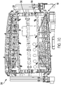
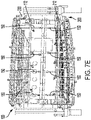
- Figures 7A-7H illustrate side views of example stages of a process for bisecting a first tubular structure 220 that is coupled to a second tubular structure 230, followed by a process for decoupling the first tubular structure 220 from the second tubular structure 230.
- the first tubular structure 220 is a fuselage and the second tubular structure 230 is a one-piece mandrel.
- the fuselage can be a composite fuselage, or, in alternative examples, the fuselage could be made of other materials.
- Figures 7A-7H are described with respect to bisecting and decoupling a fuselage, at least a portion of the operates described below can be used or modified for use in scenarios where the first tubular structure 220 comprises one or more caul plates and the second tubular structure 230 is a fuselage.
- the strongback apparatus 100 (and perhaps additionally the second strongback apparatus 200) can be positioned on a caul plate or caul plates that is/are coupled to the fuselage, which is in turn coupled to a mandrel.
- the strongback apparatus 100 (and perhaps additionally the second strongback apparatus 200) can then be used in manner similar to that described below to spread the caul plate(s) and decouple the caul plate(s) from the fuselage.
- first tubular structure 220 and the second tubular structure 230 can be other types of tubular structures.
- stages and operations described below are described as occurring in a particular order, such stages and/or operations performed as part of such stages can occur in other orders.
- Figure 7A illustrates an initial stage in the process in which the strongback apparatus 100 is positioned on the first tubular structure 220.
- an overhead crane (not shown) is used to lower the strongback apparatus 100 on the first tubular structure 220.
- the strongback apparatus 100 can also be attached (e.g., hook-latched) onto the second tubular structure 230 to further secure the strongback apparatus 100 in place until it is time to decouple the first tubular structure 220.
- a vacuum source 232 is then operated to engage the plurality of vacuum cups 114 (not explicitly denoted in Figures 7A-7H ) with the first tubular structure 220.
- air and vacuum hoses 234 are connected between the vacuum source 232 and one or more of the plurality of ports 116 of the strongback apparatus 100.
- 100-110 psi of compressed air can be supplied via the air and vacuum hoses 234 and approximately 24 in-Hg of vacuum can be used to engage the plurality of vacuum cups 114 with the first tubular structure 220.
- a controller 236 can be connected to the strongback apparatus 100, such as by plugging a cable extending from the controller 236 into a socket in the strongback apparatus 100. Connecting the controller 236 to the strongback apparatus 100 electrically couples the controller 236 to the plurality of actuators 104 and thus allows the controller 236 to be used to manipulate (e.g., move) the plurality of actuators 104.
- the controller 236 can take the form of a computing device with a processor, memory, program instructions (e.g., software code) stored in the memory, and a user interface (e.g., keyboard, display, etc.), although the controller 236 could take other forms in other examples.
- the controller 236 can have a wired or wireless connection to the vacuum source 232 so that the controller 236 can control the vacuum source 232 to engage or disengage vacuum suction.
- the vacuum source 232 can be manually operated.
- Figure 7B illustrates a next stage in the process in which the second tubular structure 230 and the first tubular structure 220 are rotated approximately 180 degrees and the same process described above with respect to Figure 7A is repeated to position the second strongback apparatus 200 on the first tubular structure 220 and engage the second plurality of vacuum cups 214 (not explicitly denoted in Figures 7A-7H ) with the first tubular structure 220.
- a plurality of straps could be attached between the strongback apparatus 100 and the second strongback apparatus 200 to provide additional security, keep the strongback apparatuses in position, and keep the first tubular structure 220 in place during trimming and bisection.
- Figures 7C-7D illustrate next stages in the process during which the first tubular structure 220 is trimmed to create holes (e.g., for windows and doors of the fuselage) and longitudinally bisected into a first section 238 and a second section 240.
- the bisection can result in the first tubular structure 220 being cut into substantially equal halves, although in other examples the first section 238 and the second section 240 might not be equal in size.
- Figure 7C illustrates a next stage in the process in which the first tubular structure 220 is trimmed and one side of the first tubular structure 220 is bisected.
- Figure 7D illustrates a next stage in the process in which the second tubular structure 230 and the first tubular structure 220 are rotated approximately 180 degrees, the first tubular structure 220 is trimmed, and the other side of the first tubular structure 220 is bisected, thereby completing the longitudinal bisection into the first section 238 and the second section 240. After the bisection is complete, the first section 238 and the second section 240 remain coupled to the second tubular structure 230.
- Figure 7E and Figure 7F illustrates next stages in the process in which the plurality of spreader arms 150 are attached to the pair of peripheral elongated members 112 and the second pair of peripheral elongated members 212.
- the proximal end of each spreader arm of the plurality of spreader arms 150 can be attached to a respective one of the pair of peripheral elongated members 112 or the second pair of peripheral elongated members 212 as described above with respect to Figure 4 .
- Figure 7G illustrates a next stage in the process in which the vacuum source 232 is operated to engage the vacuum suction cups of the plurality of actuators 104 and the second vacuum suction cups of the second plurality of actuators 204 with the first tubular structure 220. More particularly, the second vacuum suction cups of the second plurality of actuators 204 engage with the second section 240 and the plurality of actuators 104 engage with the first section 238.
- the controller 236 controls each actuator of the second plurality of actuators 204 to move from the retracted position to the extended position to attach, via vacuum suction, to the second section 240.
- the controller 236 also controls each actuator of the plurality of actuators 104 to move from the retracted position to the extended position to attach, via vacuum suction, to the first section 238.
- the controller 236 (i) controls the plurality of actuators 104 to pull the first section 238 of the first tubular structure 220 away from the second tubular structure 230 in the radially outward direction and (ii) controls the second plurality of actuators 204 to pull the second section 240 of the first tubular structure 220 away from the second tubular structure 230 in the radially outward direction.
- the vacuum suction cup of that actuator pulls the respective section of the first tubular structure 220 away from the second tubular structure 230.
- the controller 236 and the plurality of actuators 104 are configured such that the plurality of actuators 104 are controlled to synchronously pull the first section 238 away from the second tubular structure 230 in the radially outward direction.
- the controller 236 and the second plurality of actuators 204 are configured such that the second plurality of actuators 204 are controlled to synchronously pull the second section 240 away from the second tubular structure 230 in the radially outward direction. Pulling synchronously in this manner can help avoid any damage to the first tubular structure 220.
- the plurality of winch straps 152 are attached between the plurality of spreader arms 150 and the first section 238 and the second section 240, such as in the manner described above with respect to Figure 5 .
- the winches (not explicitly denoted in Figures 7G-7H ) of the plurality of spreader arms 150 are then operated to tighten the plurality of winch straps 152, thereby pulling the first section 238 and the second section 240 away from the second tubular structure 230 (or, more particularly, pulling the first section 238 and the second section 240 farther away from the second tubular structure 230).
- This additional pulling facilitated by the plurality of spreader arms 150 and the plurality of winch straps 152 can help ensure that each section of the first tubular structure is spread far enough from the second tubular structure 230, such that each section does not get caught on the second tubular structure 230 or is otherwise not damaged when decoupled from the second tubular structure 230.
- the second section 240 While pulling the second section 240 of the first tubular structure 220 away from the second tubular structure 230 with the second plurality of actuators 204 and the plurality of winch straps 152, the second section 240 is decoupled from the second tubular structure 230 with the second strongback apparatus 200.
- the overhead crane is attached onto the second strongback apparatus 200 and lifts the second section 240 off the second tubular structure 230.
- Figure 7H illustrates a next stage in the process in which the second tubular structure 230 is again rotated approximately 180 degrees and, while pulling the first section 238 of the first tubular structure 220 away from the second tubular structure 230 with the plurality of actuators 104 and the plurality of winch straps 152, the first section 238 is decoupled from the second tubular structure 230 with the strongback apparatus 100.
- the overhead crane is attached onto the strongback apparatus 100 and lifts the first section 238 off the second tubular structure 230.
- FIGS 8A-8B depict an example of an alternative way in which actuators can be coupled to the strongback apparatuses described herein.
- Figure 8A depicts actuator 120 where the proximal end 124 is mounted to, and slidable along in the radially outward direction, linear rails 250.
- the linear rails 250 can be coupled to the plurality of elongated members 110, such as to the pair of peripheral elongated members 112.
- Other components of actuator 120 are shown as well, including a rail bearing 252 and a spring 254 (e.g., a mechanical or gas spring).
- the rail bearing 252 and the spring 254 are configured to keep actuator 120 in a neutral position on the linear rails 250 (e.g., in the middle of the linear rails 250), but to still allow actuator 120 to float/move along the linear rails 250. This can allow actuator 120 to reduce shear loading of the vacuum suction cup 128 or compression/tension of the first tubular structure (not shown) during one or more of the processes described herein.
- Figure 8B depicts actuator 120 (as depicted in Figure 8A ) mounted to bracket 122.
- the linear rails 250 are mounted to bracket 122 substantially perpendicular to the actuator 120.
- the linear rails 250 would also be approximately tangential to an exterior surface of the first tubular structure (not shown) and substantially perpendicular to a longitudinal axis 256 of actuator 120.
- the longitudinal axis 256 of actuator 120 is substantially perpendicular to the exterior surface of the first tubular structure (not shown) to permit alleviation of shear loading as the first tubular structure is spread and removed from the second tubular structure.
- spring 254 or a similar mechanism can be utilized to provide opposing forces to retain actuator 120 in a neutral position.
- Figure 9 shows a flowchart of an example of a method 300 that could be used with the strongback apparatus 100 shown in Figure 1 .
- Method 300 may include one or more operations, functions, or actions as illustrated by one or more of blocks 302-308.
- the method 300 includes positioning a strongback apparatus on a first tubular structure, where the first tubular structure is coupled to a second tubular structure, and wherein the strongback apparatus comprises: an arcuate central body comprising a front end, a rear end, and a plurality of elongated members that connect the front end to the rear end, and a plurality of actuators pivotably mounted to the plurality of elongated members, wherein the plurality of actuators are configured to move in a radially outward direction and comprise (i) proximal ends pivotably mounted to the plurality of elongated members and (ii) distal ends having vacuum suction cups.
- the strongback apparatus comprises: an arcuate central body comprising a front end, a rear end, and a plurality of elongated members that connect the front end to the rear end, and a plurality of actuators pivotably mounted to the plurality of elongated members, wherein the plurality of actuators are configured to move in a radially outward direction and comprise
- the method 300 includes operating a vacuum source to engage the vacuum suction cups of the plurality of actuators with the first tubular structure.
- the method 300 includes while the vacuum suction cups of the plurality of actuators are engaged with the first tubular structure, controlling the plurality of actuators to pull the first tubular structure away from the second tubular structure in the radially outward direction.
- the method 300 includes while pulling the first tubular structure away from the second tubular structure in the radially outward direction, decoupling, with the strongback apparatus, the first tubular structure from the second tubular structure.
- the positioning of block 302 is performed by positioning the strongback apparatus on a caul plate that is coupled to a fuselage, and the decoupling of block 308 is performed by decoupling, with the strongback apparatus, the caul plate from the fuselage.
- the positioning of block 302 is performed by positioning the strongback apparatus on a fuselage that is coupled to a one-piece mandrel
- the decoupling of block 308 is performed by decoupling, with the strongback apparatus, the fuselage from the one-piece mandrel.
- controlling of block 306 is performed by controlling the plurality of actuators to synchronously pull the first tubular structure away from the second tubular structure in the radially outward direction.
- the method 300 could also involve the second strongback apparatus 200 shown in Figure 6 .
- the method 300 also includes positioning a second strongback apparatus on the first tubular structure, where the second strongback apparatus comprises: a second arcuate central body comprising a second front end, a second rear end, and a second plurality of elongated members that connect the second front end to the second rear end, and a second plurality of actuators pivotably mounted to the second plurality of elongated members, wherein the second plurality of actuators are configured to move in a radially outward direction and comprise (i) second proximal ends pivotably mounted to the second plurality of elongated members and (ii) second distal ends having second vacuum suction cups.
- the method 300 also includes after positioning the second strongback apparatus on the first tubular structure, longitudinally bisecting the first tubular structure into a first section and a second section, wherein the first section and the second section thereafter remain coupled to the second tubular structure.
- controlling of block 306 is performed after longitudinally bisecting the first tubular structure into the first section and the second section and comprises controlling the plurality of actuators to pull the first section of the first tubular structure away from the second tubular structure in the radially outward direction.
- the method 300 also includes operating the vacuum source to engage the second vacuum suction cups of the second plurality of actuators with the second section of the first tubular structure, and, while the second vacuum suction cups of the second plurality of actuators are engaged with the second section of the first tubular structure, controlling the second plurality of actuators to pull the second section of the first tubular structure away from the second tubular structure in the radially outward direction.
- the plurality of elongated members comprises a pair of peripheral elongated members that define longitudinal edges of the arcuate central body
- the second plurality of elongated members comprises a second pair of peripheral elongated members that define longitudinal edges of the second arcuate central body.
- the method 300 also includes attaching a plurality of spreader arms to the pair of peripheral elongated members and the second pair of peripheral elongated members, where the plurality of spreader arms comprise (i) proximal ends removably attached to the pair of peripheral elongated members and the second pair of peripheral elongated members and (ii) distal ends having winches and, while pulling the first section and the second section of the first tubular structure away from the second tubular structure in the radially outward direction: attaching a plurality of winch straps between the plurality of spreader arms and the first tubular structure, where the plurality of winch straps comprise (i) first ends attached to the winches and (ii) second ends having clips attached to the first tubular structure, and operating the winches to tighten the plurality of winch straps, thereby pulling the first tubular structure farther away from the second tubular structure.
- the method 300 also includes while pulling the second section of the first tubular structure away from the second tubular structure with the second plurality of actuators and the plurality of winch straps, decoupling, with the second strongback apparatus, the second section of the first tubular structure from the second tubular structure.
- the decoupling of block 308 is performed by decoupling, with the strongback apparatus, the first section of the tubular structure from the second tubular structure while pulling the first tubular structure away from the second tubular structure with the plurality of actuators and the plurality of winch straps.
- Devices or systems may be used or configured to perform logical functions presented in Figure 9 .
- components of the devices and/or systems may be configured to perform the functions such that the components are actually configured and structured (with hardware and/or software) to enable such performance.
- components of the devices and/or systems may be arranged to be adapted to, capable of, or suited for performing the functions, such as when operated in a specific manner.
- blocks in Figure 9 are illustrated in a sequential order, these blocks may also be performed in parallel, and/or in a different order than those described herein. Also, the various blocks may be combined into fewer blocks, divided into additional blocks, and/or removed based upon the desired implementation.
- each block or portions of each block may represent a module, a segment, or a portion of program code, which includes one or more instructions executable by a processor for implementing specific logical functions or steps in the process.
- the program code may be stored on any type of computer readable medium or data storage, for example, such as a storage device including a disk or hard drive. Further, the program code can be encoded on a computer-readable storage media in a machine-readable format, or on other non-transitory media or articles of manufacture.
- the computer readable medium may include non-transitory computer readable medium or memory, for example, such as computer-readable media that stores data for short periods of time like register memory, processor cache and Random Access Memory (RAM).
- the computer readable medium may also include non-transitory media, such as secondary or persistent long term storage, like read only memory (ROM), optical or magnetic disks, compact-disc read only memory (CD-ROM), for example.
- the computer readable media may also be any other volatile or non-volatile storage systems.
- the computer readable medium may be considered a tangible computer readable storage medium, for example.
- each block or portions of each block in Figure 9 may represent circuitry that is wired to perform the specific logical functions in the process.
- Alternative implementations are included within the scope of the examples of the present disclosure in which functions may be executed out of order from that shown or discussed, including substantially concurrent or in reverse order, depending on the functionality involved, as would be understood by those reasonably skilled in the art.
- system(s), device(s), and method(s) disclosed herein include a variety of components, features, and functionalities. It should be understood that the various examples of the system(s), device(s), and method(s) disclosed herein may include any of the components, features, and functionalities of any of the other examples of the system(s), device(s), and method(s) disclosed herein in any combination or any sub-combination, and all of such possibilities are intended to be within the scope of the disclosure.
Landscapes
- Engineering & Computer Science (AREA)
- Manufacturing & Machinery (AREA)
- Mechanical Engineering (AREA)
- Transportation (AREA)
- Aviation & Aerospace Engineering (AREA)
- Robotics (AREA)
- Blow-Moulding Or Thermoforming Of Plastics Or The Like (AREA)
Applications Claiming Priority (1)
| Application Number | Priority Date | Filing Date | Title |
|---|---|---|---|
| US202063125124P | 2020-12-14 | 2020-12-14 |
Publications (2)
| Publication Number | Publication Date |
|---|---|
| EP4011784A1 true EP4011784A1 (de) | 2022-06-15 |
| EP4011784B1 EP4011784B1 (de) | 2024-05-01 |
Family
ID=78821563
Family Applications (1)
| Application Number | Title | Priority Date | Filing Date |
|---|---|---|---|
| EP21211938.2A Active EP4011784B1 (de) | 2020-12-14 | 2021-12-02 | Verfahren und vorrichtungen zur entkopplung eines rumpfes von einem dorn |
Country Status (2)
| Country | Link |
|---|---|
| US (2) | US11931845B2 (de) |
| EP (1) | EP4011784B1 (de) |
Families Citing this family (1)
| Publication number | Priority date | Publication date | Assignee | Title |
|---|---|---|---|---|
| CN113799978A (zh) * | 2021-09-18 | 2021-12-17 | 珠海市边锋智驱科技有限公司 | 连杆旋翼头及无人机 |
Citations (5)
| Publication number | Priority date | Publication date | Assignee | Title |
|---|---|---|---|---|
| US5430937A (en) * | 1994-07-15 | 1995-07-11 | United Technologies Corporation | Apparatus and methods for fabricating a helicopter main rotor blade |
| FR2788743A1 (fr) * | 1999-01-22 | 2000-07-28 | Torres Ingenieria De Procesos | Dispositif pour le montage de troncons du fuselage d'aeronefs |
| US20060118235A1 (en) * | 2004-12-07 | 2006-06-08 | The Boeing Company | One-piece barrel assembly cart |
| US20160074926A1 (en) * | 2014-09-17 | 2016-03-17 | The Boeing Company | Fuselage Manufacturing System |
| EP3552773A1 (de) * | 2018-04-13 | 2019-10-16 | The Boeing Company | System und verfahren zum entfernen eines werkstücks aus einer herstellungsvorrichtung |
Family Cites Families (3)
| Publication number | Priority date | Publication date | Assignee | Title |
|---|---|---|---|---|
| US7334620B2 (en) | 2004-12-03 | 2008-02-26 | Cpc Co., Ltd. | Adhesive tape cutter |
| ITTO20060600A1 (it) * | 2006-08-11 | 2008-02-12 | Alenia Aeronautica Spa | Metodo, impianto e attrezzatura per realizzare parti in materiale composito, in particolare parti o tronchi di fusoliera per aeromobile |
| US9682788B2 (en) * | 2014-09-17 | 2017-06-20 | The Boeing Company | Fuselage manufacturing system |
-
2021
- 2021-12-02 EP EP21211938.2A patent/EP4011784B1/de active Active
- 2021-12-13 US US17/548,704 patent/US11931845B2/en active Active
-
2024
- 2024-02-08 US US18/436,732 patent/US12528145B2/en active Active
Patent Citations (5)
| Publication number | Priority date | Publication date | Assignee | Title |
|---|---|---|---|---|
| US5430937A (en) * | 1994-07-15 | 1995-07-11 | United Technologies Corporation | Apparatus and methods for fabricating a helicopter main rotor blade |
| FR2788743A1 (fr) * | 1999-01-22 | 2000-07-28 | Torres Ingenieria De Procesos | Dispositif pour le montage de troncons du fuselage d'aeronefs |
| US20060118235A1 (en) * | 2004-12-07 | 2006-06-08 | The Boeing Company | One-piece barrel assembly cart |
| US20160074926A1 (en) * | 2014-09-17 | 2016-03-17 | The Boeing Company | Fuselage Manufacturing System |
| EP3552773A1 (de) * | 2018-04-13 | 2019-10-16 | The Boeing Company | System und verfahren zum entfernen eines werkstücks aus einer herstellungsvorrichtung |
Also Published As
| Publication number | Publication date |
|---|---|
| EP4011784B1 (de) | 2024-05-01 |
| US20240181583A1 (en) | 2024-06-06 |
| US12528145B2 (en) | 2026-01-20 |
| US20220184760A1 (en) | 2022-06-16 |
| US11931845B2 (en) | 2024-03-19 |
Similar Documents
| Publication | Publication Date | Title |
|---|---|---|
| US12528145B2 (en) | Methods and apparatuses for decoupling a fuselage from a mandrel | |
| US10166641B2 (en) | Method and system for conforming assembly systems to contours of curved surfaces | |
| CN101088480B (zh) | 盒子夹紧机构 | |
| US11052613B2 (en) | Top-loading straddle-mounted pipe fusion machine | |
| US7624488B2 (en) | One-piece barrel assembly cart | |
| JP6811035B2 (ja) | 補強された複合構造体を製造するためのシステム及び方法 | |
| WO2022022602A1 (zh) | 自动化拆卸动力电池模组的装置 | |
| CN113309671B (zh) | 一种风机叶片水平安装辅助对接装置及操作方法 | |
| US8636048B2 (en) | Tire run-flat removal and installation machine | |
| US12600455B2 (en) | Aircraft cargo door actuation system with first actuator and second actuator | |
| CN112834212A (zh) | 模拟机翼后梁变形的作动装置 | |
| JPH10505295A (ja) | 連結オーバヘッドマンドレルマニピュレータ | |
| CN109411869B (zh) | 一种雷达天线对接互锁装置及方法 | |
| CN118306593A (zh) | 一种结构可二次折叠的机翼 | |
| CN214519811U (zh) | 刀具拆装辅助工具 | |
| CN119217425A (zh) | 一种快换式机械臂 | |
| JP6883145B2 (ja) | 磁性ターゲット材料を用いたスパッタリング源の磁力解放 | |
| CN111673794A (zh) | 一种机器人用夹持装置 | |
| CN221436318U (zh) | 一种汽车座椅装配夹具及设备 | |
| CN222102892U (zh) | 一种高温气动执行器 | |
| CN121269086A (zh) | 一种基于多气缸双向运动的多级展收装置和方法 | |
| CN117140561A (zh) | 操作机构及运维机器人 | |
| CN121447667A (zh) | 便于拆卸维护的工业机器人末端夹具 | |
| CN121671230A (zh) | 一种轮胎扩胎器 | |
| CN117386733A (zh) | 一种基于微创手术机器人的离合小车 |
Legal Events
| Date | Code | Title | Description |
|---|---|---|---|
| PUAI | Public reference made under article 153(3) epc to a published international application that has entered the european phase |
Free format text: ORIGINAL CODE: 0009012 |
|
| STAA | Information on the status of an ep patent application or granted ep patent |
Free format text: STATUS: THE APPLICATION HAS BEEN PUBLISHED |
|
| AK | Designated contracting states |
Kind code of ref document: A1 Designated state(s): AL AT BE BG CH CY CZ DE DK EE ES FI FR GB GR HR HU IE IS IT LI LT LU LV MC MK MT NL NO PL PT RO RS SE SI SK SM TR |
|
| STAA | Information on the status of an ep patent application or granted ep patent |
Free format text: STATUS: REQUEST FOR EXAMINATION WAS MADE |
|
| 17P | Request for examination filed |
Effective date: 20221207 |
|
| RBV | Designated contracting states (corrected) |
Designated state(s): AL AT BE BG CH CY CZ DE DK EE ES FI FR GB GR HR HU IE IS IT LI LT LU LV MC MK MT NL NO PL PT RO RS SE SI SK SM TR |
|
| RAP3 | Party data changed (applicant data changed or rights of an application transferred) |
Owner name: THE BOEING COMPANY |
|
| GRAP | Despatch of communication of intention to grant a patent |
Free format text: ORIGINAL CODE: EPIDOSNIGR1 |
|
| STAA | Information on the status of an ep patent application or granted ep patent |
Free format text: STATUS: GRANT OF PATENT IS INTENDED |
|
| INTG | Intention to grant announced |
Effective date: 20231219 |
|
| GRAS | Grant fee paid |
Free format text: ORIGINAL CODE: EPIDOSNIGR3 |
|
| GRAA | (expected) grant |
Free format text: ORIGINAL CODE: 0009210 |
|
| STAA | Information on the status of an ep patent application or granted ep patent |
Free format text: STATUS: THE PATENT HAS BEEN GRANTED |
|
| AK | Designated contracting states |
Kind code of ref document: B1 Designated state(s): AL AT BE BG CH CY CZ DE DK EE ES FI FR GB GR HR HU IE IS IT LI LT LU LV MC MK MT NL NO PL PT RO RS SE SI SK SM TR |
|
| REG | Reference to a national code |
Ref country code: GB Ref legal event code: FG4D |
|
| P01 | Opt-out of the competence of the unified patent court (upc) registered |
Effective date: 20240409 |
|
| REG | Reference to a national code |
Ref country code: CH Ref legal event code: EP |
|
| REG | Reference to a national code |
Ref country code: IE Ref legal event code: FG4D |
|
| REG | Reference to a national code |
Ref country code: DE Ref legal event code: R096 Ref document number: 602021012618 Country of ref document: DE |
|
| REG | Reference to a national code |
Ref country code: LT Ref legal event code: MG9D |
|
| REG | Reference to a national code |
Ref country code: NL Ref legal event code: MP Effective date: 20240501 |
|
| PG25 | Lapsed in a contracting state [announced via postgrant information from national office to epo] |
Ref country code: IS Free format text: LAPSE BECAUSE OF FAILURE TO SUBMIT A TRANSLATION OF THE DESCRIPTION OR TO PAY THE FEE WITHIN THE PRESCRIBED TIME-LIMIT Effective date: 20240901 |
|
| PG25 | Lapsed in a contracting state [announced via postgrant information from national office to epo] |
Ref country code: BG Free format text: LAPSE BECAUSE OF FAILURE TO SUBMIT A TRANSLATION OF THE DESCRIPTION OR TO PAY THE FEE WITHIN THE PRESCRIBED TIME-LIMIT Effective date: 20240501 |
|
| PG25 | Lapsed in a contracting state [announced via postgrant information from national office to epo] |
Ref country code: FI Free format text: LAPSE BECAUSE OF FAILURE TO SUBMIT A TRANSLATION OF THE DESCRIPTION OR TO PAY THE FEE WITHIN THE PRESCRIBED TIME-LIMIT Effective date: 20240501 Ref country code: HR Free format text: LAPSE BECAUSE OF FAILURE TO SUBMIT A TRANSLATION OF THE DESCRIPTION OR TO PAY THE FEE WITHIN THE PRESCRIBED TIME-LIMIT Effective date: 20240501 |
|
| PG25 | Lapsed in a contracting state [announced via postgrant information from national office to epo] |
Ref country code: GR Free format text: LAPSE BECAUSE OF FAILURE TO SUBMIT A TRANSLATION OF THE DESCRIPTION OR TO PAY THE FEE WITHIN THE PRESCRIBED TIME-LIMIT Effective date: 20240802 |
|
| PG25 | Lapsed in a contracting state [announced via postgrant information from national office to epo] |
Ref country code: PT Free format text: LAPSE BECAUSE OF FAILURE TO SUBMIT A TRANSLATION OF THE DESCRIPTION OR TO PAY THE FEE WITHIN THE PRESCRIBED TIME-LIMIT Effective date: 20240902 |
|
| REG | Reference to a national code |
Ref country code: AT Ref legal event code: MK05 Ref document number: 1682047 Country of ref document: AT Kind code of ref document: T Effective date: 20240501 |
|
| PG25 | Lapsed in a contracting state [announced via postgrant information from national office to epo] |
Ref country code: NL Free format text: LAPSE BECAUSE OF FAILURE TO SUBMIT A TRANSLATION OF THE DESCRIPTION OR TO PAY THE FEE WITHIN THE PRESCRIBED TIME-LIMIT Effective date: 20240501 |
|
| PG25 | Lapsed in a contracting state [announced via postgrant information from national office to epo] |
Ref country code: ES Free format text: LAPSE BECAUSE OF FAILURE TO SUBMIT A TRANSLATION OF THE DESCRIPTION OR TO PAY THE FEE WITHIN THE PRESCRIBED TIME-LIMIT Effective date: 20240501 |
|
| PG25 | Lapsed in a contracting state [announced via postgrant information from national office to epo] |
Ref country code: AT Free format text: LAPSE BECAUSE OF FAILURE TO SUBMIT A TRANSLATION OF THE DESCRIPTION OR TO PAY THE FEE WITHIN THE PRESCRIBED TIME-LIMIT Effective date: 20240501 |
|
| PG25 | Lapsed in a contracting state [announced via postgrant information from national office to epo] |
Ref country code: PL Free format text: LAPSE BECAUSE OF FAILURE TO SUBMIT A TRANSLATION OF THE DESCRIPTION OR TO PAY THE FEE WITHIN THE PRESCRIBED TIME-LIMIT Effective date: 20240501 |
|
| PG25 | Lapsed in a contracting state [announced via postgrant information from national office to epo] |
Ref country code: LV Free format text: LAPSE BECAUSE OF FAILURE TO SUBMIT A TRANSLATION OF THE DESCRIPTION OR TO PAY THE FEE WITHIN THE PRESCRIBED TIME-LIMIT Effective date: 20240501 |
|
| PG25 | Lapsed in a contracting state [announced via postgrant information from national office to epo] |
Ref country code: PT Free format text: LAPSE BECAUSE OF FAILURE TO SUBMIT A TRANSLATION OF THE DESCRIPTION OR TO PAY THE FEE WITHIN THE PRESCRIBED TIME-LIMIT Effective date: 20240902 Ref country code: PL Free format text: LAPSE BECAUSE OF FAILURE TO SUBMIT A TRANSLATION OF THE DESCRIPTION OR TO PAY THE FEE WITHIN THE PRESCRIBED TIME-LIMIT Effective date: 20240501 Ref country code: NO Free format text: LAPSE BECAUSE OF FAILURE TO SUBMIT A TRANSLATION OF THE DESCRIPTION OR TO PAY THE FEE WITHIN THE PRESCRIBED TIME-LIMIT Effective date: 20240801 Ref country code: NL Free format text: LAPSE BECAUSE OF FAILURE TO SUBMIT A TRANSLATION OF THE DESCRIPTION OR TO PAY THE FEE WITHIN THE PRESCRIBED TIME-LIMIT Effective date: 20240501 Ref country code: LV Free format text: LAPSE BECAUSE OF FAILURE TO SUBMIT A TRANSLATION OF THE DESCRIPTION OR TO PAY THE FEE WITHIN THE PRESCRIBED TIME-LIMIT Effective date: 20240501 Ref country code: IS Free format text: LAPSE BECAUSE OF FAILURE TO SUBMIT A TRANSLATION OF THE DESCRIPTION OR TO PAY THE FEE WITHIN THE PRESCRIBED TIME-LIMIT Effective date: 20240901 Ref country code: HR Free format text: LAPSE BECAUSE OF FAILURE TO SUBMIT A TRANSLATION OF THE DESCRIPTION OR TO PAY THE FEE WITHIN THE PRESCRIBED TIME-LIMIT Effective date: 20240501 Ref country code: GR Free format text: LAPSE BECAUSE OF FAILURE TO SUBMIT A TRANSLATION OF THE DESCRIPTION OR TO PAY THE FEE WITHIN THE PRESCRIBED TIME-LIMIT Effective date: 20240802 Ref country code: FI Free format text: LAPSE BECAUSE OF FAILURE TO SUBMIT A TRANSLATION OF THE DESCRIPTION OR TO PAY THE FEE WITHIN THE PRESCRIBED TIME-LIMIT Effective date: 20240501 Ref country code: ES Free format text: LAPSE BECAUSE OF FAILURE TO SUBMIT A TRANSLATION OF THE DESCRIPTION OR TO PAY THE FEE WITHIN THE PRESCRIBED TIME-LIMIT Effective date: 20240501 Ref country code: BG Free format text: LAPSE BECAUSE OF FAILURE TO SUBMIT A TRANSLATION OF THE DESCRIPTION OR TO PAY THE FEE WITHIN THE PRESCRIBED TIME-LIMIT Effective date: 20240501 Ref country code: AT Free format text: LAPSE BECAUSE OF FAILURE TO SUBMIT A TRANSLATION OF THE DESCRIPTION OR TO PAY THE FEE WITHIN THE PRESCRIBED TIME-LIMIT Effective date: 20240501 Ref country code: RS Free format text: LAPSE BECAUSE OF FAILURE TO SUBMIT A TRANSLATION OF THE DESCRIPTION OR TO PAY THE FEE WITHIN THE PRESCRIBED TIME-LIMIT Effective date: 20240801 |
|
| PG25 | Lapsed in a contracting state [announced via postgrant information from national office to epo] |
Ref country code: DK Free format text: LAPSE BECAUSE OF FAILURE TO SUBMIT A TRANSLATION OF THE DESCRIPTION OR TO PAY THE FEE WITHIN THE PRESCRIBED TIME-LIMIT Effective date: 20240501 |
|
| PG25 | Lapsed in a contracting state [announced via postgrant information from national office to epo] |
Ref country code: EE Free format text: LAPSE BECAUSE OF FAILURE TO SUBMIT A TRANSLATION OF THE DESCRIPTION OR TO PAY THE FEE WITHIN THE PRESCRIBED TIME-LIMIT Effective date: 20240501 |
|
| PG25 | Lapsed in a contracting state [announced via postgrant information from national office to epo] |
Ref country code: CZ Free format text: LAPSE BECAUSE OF FAILURE TO SUBMIT A TRANSLATION OF THE DESCRIPTION OR TO PAY THE FEE WITHIN THE PRESCRIBED TIME-LIMIT Effective date: 20240501 |
|
| PG25 | Lapsed in a contracting state [announced via postgrant information from national office to epo] |
Ref country code: RO Free format text: LAPSE BECAUSE OF FAILURE TO SUBMIT A TRANSLATION OF THE DESCRIPTION OR TO PAY THE FEE WITHIN THE PRESCRIBED TIME-LIMIT Effective date: 20240501 Ref country code: SK Free format text: LAPSE BECAUSE OF FAILURE TO SUBMIT A TRANSLATION OF THE DESCRIPTION OR TO PAY THE FEE WITHIN THE PRESCRIBED TIME-LIMIT Effective date: 20240501 |
|
| PG25 | Lapsed in a contracting state [announced via postgrant information from national office to epo] |
Ref country code: SM Free format text: LAPSE BECAUSE OF FAILURE TO SUBMIT A TRANSLATION OF THE DESCRIPTION OR TO PAY THE FEE WITHIN THE PRESCRIBED TIME-LIMIT Effective date: 20240501 |
|
| PG25 | Lapsed in a contracting state [announced via postgrant information from national office to epo] |
Ref country code: SM Free format text: LAPSE BECAUSE OF FAILURE TO SUBMIT A TRANSLATION OF THE DESCRIPTION OR TO PAY THE FEE WITHIN THE PRESCRIBED TIME-LIMIT Effective date: 20240501 Ref country code: SK Free format text: LAPSE BECAUSE OF FAILURE TO SUBMIT A TRANSLATION OF THE DESCRIPTION OR TO PAY THE FEE WITHIN THE PRESCRIBED TIME-LIMIT Effective date: 20240501 Ref country code: RO Free format text: LAPSE BECAUSE OF FAILURE TO SUBMIT A TRANSLATION OF THE DESCRIPTION OR TO PAY THE FEE WITHIN THE PRESCRIBED TIME-LIMIT Effective date: 20240501 Ref country code: EE Free format text: LAPSE BECAUSE OF FAILURE TO SUBMIT A TRANSLATION OF THE DESCRIPTION OR TO PAY THE FEE WITHIN THE PRESCRIBED TIME-LIMIT Effective date: 20240501 Ref country code: DK Free format text: LAPSE BECAUSE OF FAILURE TO SUBMIT A TRANSLATION OF THE DESCRIPTION OR TO PAY THE FEE WITHIN THE PRESCRIBED TIME-LIMIT Effective date: 20240501 Ref country code: CZ Free format text: LAPSE BECAUSE OF FAILURE TO SUBMIT A TRANSLATION OF THE DESCRIPTION OR TO PAY THE FEE WITHIN THE PRESCRIBED TIME-LIMIT Effective date: 20240501 |
|
| REG | Reference to a national code |
Ref country code: DE Ref legal event code: R097 Ref document number: 602021012618 Country of ref document: DE |
|
| PG25 | Lapsed in a contracting state [announced via postgrant information from national office to epo] |
Ref country code: IT Free format text: LAPSE BECAUSE OF FAILURE TO SUBMIT A TRANSLATION OF THE DESCRIPTION OR TO PAY THE FEE WITHIN THE PRESCRIBED TIME-LIMIT Effective date: 20240501 |
|
| PLBE | No opposition filed within time limit |
Free format text: ORIGINAL CODE: 0009261 |
|
| STAA | Information on the status of an ep patent application or granted ep patent |
Free format text: STATUS: NO OPPOSITION FILED WITHIN TIME LIMIT |
|
| 26N | No opposition filed |
Effective date: 20250204 |
|
| PG25 | Lapsed in a contracting state [announced via postgrant information from national office to epo] |
Ref country code: SI Free format text: LAPSE BECAUSE OF FAILURE TO SUBMIT A TRANSLATION OF THE DESCRIPTION OR TO PAY THE FEE WITHIN THE PRESCRIBED TIME-LIMIT Effective date: 20240501 |
|
| PG25 | Lapsed in a contracting state [announced via postgrant information from national office to epo] |
Ref country code: MC Free format text: LAPSE BECAUSE OF FAILURE TO SUBMIT A TRANSLATION OF THE DESCRIPTION OR TO PAY THE FEE WITHIN THE PRESCRIBED TIME-LIMIT Effective date: 20240501 |
|
| REG | Reference to a national code |
Ref country code: CH Ref legal event code: PL |
|
| PG25 | Lapsed in a contracting state [announced via postgrant information from national office to epo] |
Ref country code: LU Free format text: LAPSE BECAUSE OF NON-PAYMENT OF DUE FEES Effective date: 20241202 |
|
| PG25 | Lapsed in a contracting state [announced via postgrant information from national office to epo] |
Ref country code: SE Free format text: LAPSE BECAUSE OF FAILURE TO SUBMIT A TRANSLATION OF THE DESCRIPTION OR TO PAY THE FEE WITHIN THE PRESCRIBED TIME-LIMIT Effective date: 20240501 |
|
| REG | Reference to a national code |
Ref country code: BE Ref legal event code: MM Effective date: 20241231 |
|
| PG25 | Lapsed in a contracting state [announced via postgrant information from national office to epo] |
Ref country code: BE Free format text: LAPSE BECAUSE OF NON-PAYMENT OF DUE FEES Effective date: 20241231 |
|
| PG25 | Lapsed in a contracting state [announced via postgrant information from national office to epo] |
Ref country code: CH Free format text: LAPSE BECAUSE OF NON-PAYMENT OF DUE FEES Effective date: 20241231 |
|
| PG25 | Lapsed in a contracting state [announced via postgrant information from national office to epo] |
Ref country code: IE Free format text: LAPSE BECAUSE OF NON-PAYMENT OF DUE FEES Effective date: 20241202 |
|
| PGFP | Annual fee paid to national office [announced via postgrant information from national office to epo] |
Ref country code: GB Payment date: 20251229 Year of fee payment: 5 |
|
| PGFP | Annual fee paid to national office [announced via postgrant information from national office to epo] |
Ref country code: FR Payment date: 20251226 Year of fee payment: 5 |
|
| PG25 | Lapsed in a contracting state [announced via postgrant information from national office to epo] |
Ref country code: CY Free format text: LAPSE BECAUSE OF FAILURE TO SUBMIT A TRANSLATION OF THE DESCRIPTION OR TO PAY THE FEE WITHIN THE PRESCRIBED TIME-LIMIT; INVALID AB INITIO Effective date: 20211202 |
|
| PGFP | Annual fee paid to national office [announced via postgrant information from national office to epo] |
Ref country code: DE Payment date: 20251229 Year of fee payment: 5 |